JP4257298B2 - Device for displaying facial features - Google Patents
Device for displaying facial featuresDownload PDFInfo
- Publication number
- JP4257298B2 JP4257298B2JP2005019271AJP2005019271AJP4257298B2JP 4257298 B2JP4257298 B2JP 4257298B2JP 2005019271 AJP2005019271 AJP 2005019271AJP 2005019271 AJP2005019271 AJP 2005019271AJP 4257298 B2JP4257298 B2JP 4257298B2
- Authority
- JP
- Japan
- Prior art keywords
- participant
- local
- remote
- display
- flexible display
- Prior art date
- Legal status (The legal status is an assumption and is not a legal conclusion. Google has not performed a legal analysis and makes no representation as to the accuracy of the status listed.)
- Expired - Fee Related
Links
Images


Classifications
- H—ELECTRICITY
- H04—ELECTRIC COMMUNICATION TECHNIQUE
- H04N—PICTORIAL COMMUNICATION, e.g. TELEVISION
- H04N7/00—Television systems
- H04N7/14—Systems for two-way working
- H04N7/141—Systems for two-way working between two video terminals, e.g. videophone
- H04N7/142—Constructional details of the terminal equipment, e.g. arrangements of the camera and the display
- H04N7/144—Constructional details of the terminal equipment, e.g. arrangements of the camera and the display camera and display on the same optical axis, e.g. optically multiplexing the camera and display for eye to eye contact
- G—PHYSICS
- G06—COMPUTING OR CALCULATING; COUNTING
- G06T—IMAGE DATA PROCESSING OR GENERATION, IN GENERAL
- G06T15/00—3D [Three Dimensional] image rendering
- G06T15/02—Non-photorealistic rendering
Landscapes
- Engineering & Computer Science (AREA)
- Computer Graphics (AREA)
- Physics & Mathematics (AREA)
- General Physics & Mathematics (AREA)
- Theoretical Computer Science (AREA)
- Multimedia (AREA)
- Signal Processing (AREA)
- Two-Way Televisions, Distribution Of Moving Picture Or The Like (AREA)
- User Interface Of Digital Computer (AREA)
- Liquid Crystal Display Device Control (AREA)
- Control Of Indicators Other Than Cathode Ray Tubes (AREA)
- Controls And Circuits For Display Device (AREA)
Description
Translated fromJapanese本発明は、TV会議などの遠隔ミーティングにおいて参加者の顔の特徴を伝達して表示する装置に関する。 The present invention relates to an apparatus for transmitting and displaying participant's facial features in a remote meeting such as a TV conference.
TV会議は、人々が対話する様式を大幅に変えることを約束するものである。飛行機旅行が高価であり、化石燃料が高くつき、テロリズムおよび新しい感染性疾病がある時代では、効果的なTV会議が大いに必要とされる。効果的なTV会議は、向かい合ってのミーティングのインパクトを実現しようとする、すなわちテレプレゼンス(telepresence)を生み出さそうとしなければならない。TV会議を向かい合っての対話により近づけるようにするためには、非言語情報をすべての参加者に伝えること、各参加者の中での視線を検出して伝えること、アイコンタクトならびに他の視覚情報および聴覚情報を維持することを含む複数の要因を改善する必要がある。 Video conferencing promises to significantly change the way people interact. In an era where air travel is expensive, fossil fuels are expensive, there is terrorism and new infectious diseases, effective video conferencing is greatly needed. An effective video conference must try to realize the impact of a face-to-face meeting, i.e. create telepresence. In order to make the video conference closer to the face-to-face conversation, non-verbal information is communicated to all participants, the gaze within each participant is detected and communicated, eye contact and other visual information There is a need to improve multiple factors, including maintaining auditory information.
現行のTV会議およびヒューマン−コンピュータ対話技術は、多くの場合に以下からなる。すなわち、ローカルカメラが参加者の正面の画像を録画し、その情報をリモート位置のフラットディスプレイに送信する。リモート参加者の画像がリモートカメラを使用して録画され、ローカル参加者に向けてローカルフラットディスプレイ上に表示される。録画するカメラは表示と一致しないため、参加者は話している間または聞いている間にアイコンタクトを維持することができない。さらに、離れた場所にいる人の視線位置(すなわち、その人が見ている場所)を求めることは困難である。このような非言語情報は、人の関心の表れおよび関わり合い、理解等のレベルを提供する。最後に、現行のTV会議は、良好な距離(または奥行)知覚および画像の三次元提示を提供しない。複数のカメラアングルには特殊なガラスまたはゴーグルが必要であり、このことは消費者へのアピールを制限することが証明されている。 Current video conferencing and human-computer interaction technologies often consist of: That is, the local camera records an image of the front of the participant and transmits the information to the flat display at the remote location. An image of the remote participant is recorded using the remote camera and displayed on the local flat display for the local participant. Since the recording camera does not match the display, participants cannot maintain eye contact while speaking or listening. Furthermore, it is difficult to determine the line-of-sight position of a person at a distant place (that is, the place where the person is looking). Such non-linguistic information provides a level of expression and engagement, understanding, etc. of human interest. Finally, current TV conferences do not provide good distance (or depth) perception and three-dimensional presentation of images. Multiple camera angles require special glass or goggles, which has been proven to limit consumer appeal.
同様に、ヒューマン−コンピュータ対話の場合には、一般的な手法は平坦な動画化された画像をフラットスクリーン上に投影するというものである。コンピュータの人物像の視線は、対話中の人のメッセージまたは位置に関連しない。表示は二次元であり、むしろ嵩張るため、ロボット工学等のモバイルプラットフォームで使用することは難しく、高価である。 Similarly, in the case of human-computer interaction, a common approach is to project a flat animated image onto a flat screen. The line of sight of the human figure on the computer is not related to the message or position of the person being interacted with. The display is two-dimensional and rather bulky, making it difficult and expensive to use on mobile platforms such as robotics.
本発明は、上記および他の問題に解決策を提供するとともに、よりリアルな表現および表示と、遠隔ミーティング中の視線保存を通してより真に迫ったコミュニケーション経験とを提供する。 The present invention provides a solution to these and other problems, as well as providing a more realistic representation and display and a more truly communicative experience through gaze preservation during a remote meeting.
本発明は、限定ではなく例として添付図面の図に示される。 The present invention is illustrated by way of example and not limitation in the figures of the accompanying drawings.
本発明の一態様は、顔の特徴を表示する方法を特徴とする。表示動作は、顔の特徴を有する画像を非平面表面上に生成するステップと、画像を非平面表面上に配置して、注視あるいは視線の方向を示し、顔の特徴に関連する非言語コミュニケーションを向上させるステップとを含んでなる。 One aspect of the invention features a method for displaying facial features. The display operation includes generating an image having facial features on a non-planar surface, placing the image on the non-planar surface, indicating gaze or gaze direction, and performing non-verbal communication related to facial features. Improving.
本発明の別の態様は、顔の特徴を表示する装置を含む。この装置は、非平面表面、顔の特徴を有する画像を非平面表面上に作成する画像生成装置と、非平面表面上に画像を配置して、注視または視線の方向を示し、顔の特徴に関連する非言語コミュニケーションを向上させる位置決めシステムとを含んでなる。 Another aspect of the present invention includes an apparatus for displaying facial features. This device creates an image with a non-planar surface and facial features on the non-planar surface, and places the image on the non-planar surface to indicate the direction of gaze or line of sight, And a positioning system that enhances related non-verbal communication.
図1は、一実施形態による非平面ディスプレイを使用するビデオシステムを示す。システム100は、第1の位置にいるローカルユーザ110と、第1の位置にある1台以上のカメラ106および108と、第1の位置にあるマイクロフォン112と、第2の位置にある、顔の特徴104が表示される非平面ディスプレイ102とを含む。 FIG. 1 illustrates a video system using a non-planar display according to one embodiment. The system 100 includes a
この実施形態での非平面ディスプレイ102は、画像生成表示表面を有する三次元頭部形状を含む。一実施形態では、非平面ディスプレイ102は、非平面頭部の表面をカバーするように傾けられるフレキシブルエリア保存投影ディスプレイパッチから形成される。エリア保存パッチは、表面を正確にカバーするように設計され、非平面表面上に折り重なり、重複または間隙なしでそれぞれのエッジに沿って交わる。このような実施形態では、顔の特徴がローカルユーザからシームレスに見えるようにするために、コンピュータまたは他の処理装置は各ディスプレイパッチ上に見えるように画像を配置する。 The
カメラ106およびカメラ108は、マイクロフォン112がスピーチを収集している間に、ローカルユーザ110の2つの対応するビデオ画像を撮影する。そして、これらの装置は、非平面ディスプレイ102およびスピーカでそれぞれ再生するために、ビデオ情報およびオーディオ情報を送信する。実施態様により、画像が併合され、投影歪みが補正され、非平面頭部ディスプレイ102上に表示される。ローカルユーザ110が頭部を回転させると、表示システムは非平面ディスプレイ102上の画像を回転させる。ローカルユーザ110が目をいずれかの方向に向けると、画像104の目の部分も対応して変化する。このようにして、視線方向および感情の存在および非言語コミュニケーションの他の指示は、非平面ディスプレイ102を観察している人に向けて明確に示される。
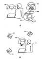
図2は、ローカルユーザ202およびリモートユーザ210によって使用されるTV会議の実施形態を示す。この図は、斜視画像を収集して、ローカルユーザのアイコンタクトと視線情報(gaze information)と他の非言語手掛かりとの保存を助ける実施形態を示す。この構成は、ローカルユーザ202の場所にある頭部形状非平面ディスプレイ204と、リモートユーザ210の場所にある頭部形状非平面ディスプレイ206と、各ディスプレイ上に現れる顔の画像の各目の位置に実質的に埋め込まれるカメラ208とを含む。 FIG. 2 shows an embodiment of a video conference used by
ミーティングまたは他の対話中に、ローカルユーザ202はカメラ209を通してリモートユーザ210に話しかける。非平面ディスプレイ204上のリモートユーザ210の画像に組み合わせられたカメラ209の位置により、ローカルユーザ202が、リモートユーザ210とアイコンタクトをとるか、またはアイコンタクトを避けることが助けられる。同様に、リモートユーザ210は、図示のように位置決めされた非平面ディスプレイ204上のローカルユーザ208の画像と組み合わせられたカメラ208の位置により、ローカルユーザ202とのアイコンタクトをよりよく制御することができる。一対のカメラ208および209によって収集された視点情報は、ローカルユーザ202およびリモートユーザ208が両者とも非言語情報を識別する能力を大幅に向上させる。たとえば、視点情報(perspective information)は、顔の表現の対称性または非対称性、視線またはアイコンタクトまたは人とのコミュニケーション中に使用される顔の表現の他の任意の様々な部分に相対する顔の表現の要素の位置についての情報を含む。 During a meeting or other interaction, the
実質的にリモートユーザ210の画像の片目または両目の位置に1台以上のカメラを非平面ディスプレイ204上に位置決めすることにより、リモートユーザ210に関しても視線情報を同様に保存することができる。 By positioning one or more cameras on the non-planar display 204 substantially at the position of one or both eyes of the image of the
図3Aと図3Bと図4とは、異なる実施形態により視線を保存する異なるカメラ構成を提供する。図3Aに示す一実施態様では、カメラ302は、実質意的に画像の一方の目が表される領域に配置され、他方の目に対応するエリア304にカメラは現れない。この構成では、カメラ302は片目の視点から画像を収集し、他方の目からのエリア304は視線情報をディスプレイ表面上に表示する。エリア304における片目からの視線情報は、他のどこかで使用するために、カメラ302が視線情報を収集する間の視線の程度を保存する。 3A, 3B, and 4 provide different camera configurations that preserve line-of-sight according to different embodiments. In one embodiment shown in FIG. 3A, the
図3Bに示す別の実施態様では、半透明ディスプレイ308により、1台以上のローカルカメラ306を使用してビデオを同時に収集しながらリモートユーザの両目310の画像を生成することができる。この構成では、より多くの視線情報が、非平面ディスプレイ上に表示されるリモートユーザの両目から保存される。同様に、一対のカメラ306も、非平面ディスプレイ、平面ディスプレイ、またはビデオシステムの他のどこかを使用してリモートユーザが見ているローカルユーザからより多くの視線情報および視点情報を収集する。カメラ306の位置が非平面ディスプレイ上のリモートユーザの目310の位置に近いほど、より高い程度の視線情報および非言語情報が保存される。 In another embodiment shown in FIG. 3B, the
図4に示すさらに別の構成では、カメラ312は非平面ディスプレイ上に現れる顔の特徴の画像のうちの鼻梁付近に配置された開口部314を通してローカルユーザのビデオを収集する。この実施形態は、人が鼻梁に固定された視線と、目そのもの自体に固定された視線とを区別することができないことを利用する。カメラ312は、ローカルユーザから視線情報を収集するが、どちらの目にも直接位置決めされていないため、先に述べた代替の実施形態ほど多くの視点情報を保存しない。しかし、目316および目318は、ローカルユーザに向けて非平面ディスプレイ上に表示され、リモートユーザの視線を反映するように現れる。したがって、この実施形態は視線を生成し、それでもなお視線を保存するように動作することにより費用効果が大きい場合がある。 In yet another configuration shown in FIG. 4, the
図5Aと図5Bと図6とは、実施形態による非平面表面上に顔の画像を生成する様々な可能性を示す。図5Aは、頭部形状非平面表面404に固定されたフレキシブルディスプレイ402の使用を示す。等面積マッピングも使用して、エリア408aと408bと408cと408dとを有するフレキシブルディスプレイのセグメントから非平面ディスプレイ406を構築することができる。等面積マッピングは、面積が同じままであり、平坦でフレキシブルな材料が湾曲した表面をカバーすることができるように、湾曲した表面を平坦な材料上にマッピングする設計方法である。この例では、エリア408aはリモートユーザの右頬部分に対応するフレキシブルディスプレイ材料であり、エリア408bはリモートユーザの左頬部分に対応し、エリア408cはリモートユーザの顔の中央エリアに対応し、エリア408dはリモートユーザの額領域に対応する。これら様々なエリアをカバーするフレキシブルディスプレイ材料は、視点および他の多くの非言語手掛かり(nonverbal cue)を通して、視線や顔の表情やジェスチャーを記述する。 5A, 5B, and 6 illustrate various possibilities for generating a facial image on a non-planar surface according to embodiments. FIG. 5A illustrates the use of a
図5Bは、複数のプロジェクタ410と412と414がローカルユーザ418に提示するために画像を非平面ディスプレイ表面416上に作成する実施形態を示す。この実施形態は、現在利用可能な技術を使用するため、最も容易で低コストに実施することができるという利点を有する。非平面表面416は、円筒形表面もしくはマネキンの頭部、または人の三次元頭部に似た他の表面を使用して実施することができる。 FIG. 5B illustrates an embodiment in which
プロジェクタ410と412と414とを非平面ディスプレイ416上で使用するには、適宜機能するために追加の処理および画像向上動作も必要な場合がある。画像処理ルーチンは、リモートユーザの画像を処理して、顔を非平面ディスプレイ表面416の中心軸にセンタリングしたまま保つことができる。顔認識動作を使用して、非平面ディスプレイ416の中心軸と比較して、ビデオ撮影されているリモートユーザの中心軸を特定することができる。リモートユーザの中心軸は、軸位置が非平面ディスプレイ表面416に一致するまでリモートユーザの撮影中の1以上の画像をシフトすることにより、位置合わせすることができる。 Using
別の実施形態は、非平面ディスプレイ416上に適宜再現されない顔の特徴を処理し補正することができる。たとえば、リモートユーザの画像を撮影中のカメラにより導入される物体またはひずみが、顔の特徴を場合によっては隠し、影を落とす場合がある。顔の特徴または表情についての統計情報を使用して、影または暗いエリアを表示する代わりにこれらエリアまたはドロップアウトしたものを再作成することができる。たとえば、頬や額の比較的に平坦なエリアの認識を用いて、これら領域でのエリアを平滑化または近似し、表示される画像に連続性を提供することができる。これは、視線を維持し、いくらかの収差に起因する歪みを回避するに十分に正確な顔の特徴の再現を提供する。 Another embodiment may process and correct facial features that are not properly reproduced on the
さらに別の画像処理態様では、リモートユーザの比較的小さな頭部の動きを解像することができる。この場合には、顔認識ルーチンおよび目追跡ルーチンも使用されて、画像を撮影中のカメラに対するリモートユーザの頭部の回転位置が特定される。視線およびローカルユーザ418とのアイコンタクトを維持するために、ローカルユーザの画像を撮影中のカメラ416は、リモートユーザの新しい目の位置を反映するように変更される。たとえば、実施態様では、リモートユーザからの頭部の回転程度に応じて、右側または左側のカメラ416から撮影された画像を収集して使用することができる。結果として得られる左画像、右画像、もしくはこれらの組み合わせを使用することにより、リモートユーザは、新しくより正確なアイコンタクト位置とともにローカルユーザ418が向けた異なる視点を見ることができる。 In yet another image processing aspect, a relatively small head movement of the remote user can be resolved. In this case, the face recognition routine and the eye tracking routine are also used to identify the rotational position of the remote user's head relative to the camera that is taking the image. In order to maintain the line of sight and eye contact with the
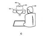
図6は、一実施形態による半透明非平面表面上に内部投影するシステムを示す。このシステムは、半透明非平面表面420と、光源422と、画像をローカルユーザ426に提示するための液晶光弁(liquid crystal light valve)424とを含む。光弁424は、光源422をフィルタリングし、結果として得られる画像を半透明非平面表面420上に投影する。このシステムは、表示ソースおよび半透明非平面表面420が内蔵されて搬送できるため有利である。先に述べたほかのシステムのように、リモートユーザの投影画像は顔の表情を含み、ローカルユーザ426に向けて視線および他の非言語手掛かりを保存する。 FIG. 6 illustrates a system for internal projection onto a translucent non-planar surface according to one embodiment. The system includes a translucent
図7は、一実施形態による、ユーザの顔の特徴を収集して非平面ディスプレイ上に表示することに関わるステップを示すフローチャートである。まず、非平面表示装置が、リモートユーザの顔の特徴の1以上の画像を受信する(ステップ502)。そして、先に述べたように、1台以上のカメラを使用して画像を収集し、非平面表示装置上に画像を表示することができる。たとえば、非平面ディスプレイ上に位置決めされた各目にカメラをほぼ一致させて、非平面ディスプレイ上の片目付近または一対の目の間の鼻梁付近に配置することができる。 FIG. 7 is a flowchart illustrating steps involved in collecting and displaying a user's facial features on a non-planar display according to one embodiment. First, the non-planar display device receives one or more images of facial features of the remote user (step 502). As described above, the image can be collected using one or more cameras and displayed on the non-flat display device. For example, the camera for each eye positioned on the non-planar display can be substantially matched and placed near one eye on the non-planar display or near the nose bridge between a pair of eyes.
次いで、撮影されたリモートユーザの画像が非平面表面上に位置決めされ、リモートユーザのローカルユーザに対する視線を示す(ステップ504)。リモートユーザの顔の表情は、画像の目を、目が非平面ディスプレイ上に現れるであろう位置に、またはその位置付近に位置決めすることによって視線を保存する。また、様々な画像から収集された視点情報により、視線および他の非言語情報を、非平面ディスプレイを見ているローカルユーザに伝えることが助けられる。先に述べたように、顔の画像は、いくつかのプロジェクタを使用して非平面ディスプレイ上に投影することも、非平面表面に取り付けられたフレキシブルディスプレイを使用して表示することも、または半透明非平面表面内からの画像の内部投影を通して表示することもできる。 The captured image of the remote user is then positioned on the non-planar surface, indicating the line of sight of the remote user with respect to the local user (step 504). The facial expression of the remote user preserves the line of sight by positioning the eye of the image at or near the position where the eye will appear on the non-planar display. Also, viewpoint information collected from various images helps to convey gaze and other non-linguistic information to local users looking at non-planar displays. As mentioned earlier, facial images can be projected onto a non-planar display using several projectors, displayed using a flexible display attached to a non-planar surface, or semi- It can also be displayed through an internal projection of the image from within the transparent non-planar surface.
上記動作と同時に、または平行して、ローカルユーザの近くの非平面ディスプレイに位置決めされたカメラは、ローカルユーザの顔の画像または表情の画像を収集する(ステップ506)。複数の画像によりローカルユーザの様々な視点を収集して、ローカルユーザの視線および他の非言語手掛かりの取り込みも同様に向上させることができる。用途に応じて、様々な画像処理ルーチンを収集された画像に適用して、頭部の回転と、頭部の傾きと、視線およびリモートユーザとローカルユーザとの間のアイコンタクトの保存に干渉する可能性のある画像中の他のばらつきとを補正することができる。この処理が完了すると、ローカルユーザの画像はリモートユーザの非平面ディスプレイ上に表示するために送信され(ステップ508)、上の動作が繰り返される。上の動作は特定の順序で提供されるが、上の動作は全体的に並列に、または様々な順序で行って、非平面ディスプレイ上への画像形成のパフォーマンスおよび効率を向上させることができることが理解される。 Simultaneously or in parallel with the above operation, the camera positioned on the non-planar display near the local user collects images of the local user's face or facial expression (step 506). Various viewpoints of the local user can be collected from a plurality of images, and the capture of the local user's line of sight and other non-language cues can be improved as well. Depending on the application, various image processing routines can be applied to the collected images to interfere with head rotation, head tilt, line of sight and preservation of eye contact between remote and local users. Other variations in possible images can be corrected. When this process is complete, the local user's image is sent for display on the remote user's non-planar display (step 508) and the above operations are repeated. The above operations are provided in a specific order, but the above operations can be performed in parallel or in various orders to improve the performance and efficiency of imaging on non-planar displays. Understood.
図8は、本明細書に詳述する装置または方法を実行する一実施態様において使用されるシステム600のブロック図である。システム600は、実行プログラムを保持するメモリ602(通常、ランダムアクセスメモリ(RAM)またはフラッシュROM等の読み取り専用メモリ(ROM))と、ディスプレイ、すなわち出力装置をインタフェースして駆動することが可能な提示装置インタフェース604と、プロセッサ606と、ドライバまたは他の頻繁に使用されるプログラムを保持するプログラムメモリ608と、データ通信のためのネットワーク通信ポート610と、補助記憶装置コントローラおよび入出力(I/O)ポートを有する補助記憶装置612と、コントローラ614とを含んでなり、これらは共にバス616を介して動作可能に結合される。システム600は、たとえば、フィールドプログラマブルゲートアレイ(FPGA)技術を使用してROMに予めプログラムすることができ、またプログラムを別のソース(たとえば、フロッピー(登録商標)ディスク、CD−ROM、または別のコンピュータから)ロードすることによってプログラム(または再プログラム)することができる。また、システム600は、カスタマイズされた特定用途向け集積回路(ASIC)を使用して実施することもできる。 FIG. 8 is a block diagram of a
一実施態様では、メモリ602は、非平面画像収集構成要素618、非平面画像処理構成要素620と、非平面ディスプレイ構成要素622と、非平面頭部追跡構成要素624と、システム600において上の構成要素の1以上を処理する際に使用されるシステム資源を管理するランタイムモジュール626とを含む。 In one implementation, the
図示のように、これらの様々なモジュールは単一のコンピュータシステムに見られる。しかし、代替の実施態様では、これら構成要素を1以上の異なる構成要素に分散させて、処理需要とスケーラビリティと高可用性と他の設計制約とに適応することができる。同様に、図8に示す構成要素は離散し互いに別個に示される。代替の実施態様は、これら構成要素の1以上のものを組み合わせて、より高い効率、より低いコスト、または大規模企業または小規模動作環境において実施形態の実施に必要な他の任意の設計制約を実現することができる。 As shown, these various modules are found in a single computer system. However, in alternative embodiments, these components can be distributed across one or more different components to accommodate processing demands, scalability, high availability, and other design constraints. Similarly, the components shown in FIG. 8 are discrete and shown separately from each other. Alternative implementations combine one or more of these components to provide higher efficiency, lower cost, or any other design constraints necessary to implement embodiments in a large enterprise or small operating environment. Can be realized.
非平面画像収集構成要素618は、非平面ディスプレイに関連する1台以上のカメラからローカルユーザの画像を収集する。非平面画像処理構成要素620は、収集された画像に対して1以上の画像処理動作を行い、結果として非平面ディスプレイ上の表示を向上させる。先に述べたように、これら画像処理動作は、リモートユーザの頭部の傾きの補正と、リモートユーザの頭部の回転の考慮、収差または歪みを受ける顔の画像のエリアの平滑化と、視線および/または他の非言語手掛かりの保存を向上させる他の任意のプロセスとを含む。 The non-planar
非平面ディスプレイ構成要素622は、画像をさらに処理し、本明細書に説明した詳細に従って設計された特定の表示を作成する。この非平面ディスプレイ構成要素622は、プロジェクタ、フレキシブル表示装置、非平面ディスプレイ内部用の表示ディスプレイ、または他の任意の様々な実施形態とより良好に動作するように画像を変更することができる。 The
非平面頭部追跡構成要素624は、画像を収集して送信しているときにリモートユーザの頭部の位置を追跡する1以上の動作を含む。この非平面頭部追跡構成要素624は、リモートユーザの目ならびにリモートユーザの完全な顔の特徴を追跡する動作を実施することができる。 The non-planar head tracking component 624 includes one or more operations that track the position of the remote user's head as the image is being collected and transmitted. This non-planar head tracking component 624 can perform operations to track the remote user's eyes as well as the remote user's complete facial features.
例および実施態様について述べたが、これらは本発明のいずれの態様も限定する働きをするものではない。したがって、本発明の実施態様はアナログ回路、デジタル電子回路、コンピュータハードウェア、ファームウェア、ソフトウェア、またはこれらの組み合わせで実施することができる。本発明の装置は、アナログ電子回路、またはプログラマブルプロセッサにより実行される機械読み取り可能な記憶装置に有形に具現化されるコンピュータプログラム製品内のデジタル電子回路を使用することによって実施することができ、本発明の方法ステップは、入力データに対して動作して出力を生成することにより、本発明の機能を実行するプログラム命令を実行するプログラマブルプロセッサによって行うことができる。本発明は、結合されてデータ記憶システムからデータおよび命令を受け取り、データおよび命令をデータ記憶システムに送る少なくとも1つのプログラマブルプロセッサと、少なくとも1つの入力装置と、少なくとも1つの出力装置とを含むプログラマブルシステムで実行可能な1以上のコンピュータプログラムにおいて有利に実施することができる。各コンピュータプログラムは、高水準手続き型またはオブジェクト指向型プログラミング言語、または所望であればアセンブリ言語または機械語で実装することができ、いずれの場合でも、言語はコンパイル型言語またはインタプリタ型言語でありうる。適したプロセッサとしては、例として、汎用マイクロプロセッサおよび特定用途マイクロプロセッサの両方が挙げられる。一般に、プロセッサは、命令およびデータを読み取り専用メモリおよび/またはランダムアクセスメモリから受け取る。一般に、コンピュータはデータファイルを記憶する1以上の大容量記憶装置を含み、このような装置としては、内部ハードディスクおよびリムーバブルディスク等の磁気ディスクと、光磁気ディスクと、光ディスクとが挙げられる。コンピュータプログラム命令およびデータを有形に具現することに適した記憶装置としては、例としてEPROMやEEPROMやフラッシュメモリデバイス等の半導体メモリデバイスと、内部ハードディスクおよびリムーバブルディスク等の磁気ディスクと、光磁気ディスクと、CD−ROMディスクとを含むすべての形態の不揮発性メモリを挙げることができる。上記のいずれもASICにより補足されても、またはASIC内に組み込まれていてもよい。 While examples and embodiments have been described, they do not serve to limit any aspect of the present invention. Thus, embodiments of the invention can be implemented in analog circuitry, digital electronic circuitry, computer hardware, firmware, software, or a combination thereof. The apparatus of the present invention can be implemented by using digital electronic circuits in a computer program product tangibly embodied in analog electronic circuits or machine-readable storage devices executed by a programmable processor, Inventive method steps may be performed by a programmable processor that executes program instructions to perform the functions of the present invention by operating on input data to produce output. The present invention relates to a programmable system including at least one programmable processor coupled to receive data and instructions from a data storage system and to send the data and instructions to the data storage system, at least one input device, and at least one output device. Can advantageously be implemented in one or more computer programs executable. Each computer program can be implemented in a high-level procedural or object-oriented programming language, or assembly language or machine language if desired, and in any case, the language can be a compiled or interpreted language . Suitable processors include, by way of example, both general purpose and special purpose microprocessors. Generally, a processor will receive instructions and data from a read-only memory and / or a random access memory. Generally, a computer includes one or more mass storage devices that store data files, such devices include magnetic disks such as internal hard disks and removable disks, magneto-optical disks, and optical disks. Examples of storage devices suitable for tangibly embodying computer program instructions and data include semiconductor memory devices such as EPROM, EEPROM, and flash memory devices, magnetic disks such as internal hard disks and removable disks, and magneto-optical disks. And all forms of non-volatile memory including CD-ROM discs. Any of the above may be supplemented by or incorporated within the ASIC.
特定の実施形態について例示を目的として本明細書に述べたが、本発明の精神および範囲から逸脱することなく様々な変更を行うことが可能である。たとえば、様々なディスプレイ技術が市販されており、記載の本発明の具現に使用することが可能である。さらに、提示される画像の作成は様々な方法で行うことができる。非平面表面上に現れる画像は、ビデオカメラによって取り込まれて、コンピュータアルゴリズムまたはコンピュータハードウェアによって処理されて作成されたリモートユーザの画像であっても、またはヒューマン−コンピュータ対話のためにコンピュータにより生成されるものであってもよい。したがって、本発明は上記実施態様に限定されず、添付の特許請求の範囲により、それぞれの等価物の全範囲を鑑みて規定される。 While particular embodiments have been described herein for purposes of illustration, various modifications may be made without departing from the spirit and scope of the invention. For example, various display technologies are commercially available and can be used to implement the described invention. Furthermore, the image to be presented can be created in various ways. The image that appears on the non-planar surface may be a remote user image captured by a video camera and processed by a computer algorithm or computer hardware, or generated by a computer for human-computer interaction. It may be a thing. Accordingly, the invention is not limited to the embodiments described above, but is defined by the appended claims in view of the full scope of each equivalent.
602 メモリ
604 非平面ディスプレイインタフェース
606 プロセッサ
608 プログラムメモリ
610 ネットワーク通信ポート
612 補助記憶装置
614 I/Oポート
618 非平面画像収集構成要素
620 非平面画像処理構成要素
622 非平面ディスプレイ構成要素
624 非平面頭部追跡構成要素
626 ランタイムモジュール602
Claims (6)
Translated fromJapanese前記ローカルロケーションと前記リモートロケーションとに設けられたフレキシブルディスプレイであって、前記参加者の頭部の表面をカバーするように傾けられるフレキシブルエリア保存投影ディスプレイパッチから形成されるものである、フレキシブルディスプレイと、
前記フレキシブルディスプレイ上に表示された前記ローカルロケーションに位置するローカル参加者と前記リモートロケーションに位置するリモート参加者との顔の画像の目の位置にそれぞれ配置されているビデオカメラと、
前記ビデオカメラによって撮影された前記ローカル参加者と前記リモート参加者との視線および頭部の向きについての情報を、前記ロケーション以外に設けられた前記フレキシブルディスプレイに向けてそれぞれ送信するとともに、前記ローカル参加者と前記リモート参加者との視線および頭部の向きを前記ロケーションに設けられた前記ビデオカメラに追跡させるプロセッサと
を含んでなる、テレビ会議システム。A video conference system provided between a local participant located at a local location and a remote participant located at a remote location,
Aflexible display provided at the local location and the remote location, wherein the flexible display is formed from a flexible area storage projection display patch that is tilted to cover a surface of the participant's head ; ,
A video camera disposed at each eye position of a face image of a local participant located at the local location and a remote participant located at the remote location displayed on theflexible display;
Information about the line of sight and head orientation of the local participant and the remote participant taken by the video camera is transmitted to theflexible display provided outside the location, and the local participation is transmitted. A video conferencing system comprising: a processor that causes the video camera provided at the location to track the line-of-sight and head orientation of a person and the remote participant.
前記テレビ会議システムのプロセッサに対し、
前記リモートロケーションに設けられたフレキシブルディスプレイ内に配置されたビデオカメラによって、前記リモート参加者の視線および頭部の向きについての情報を撮影させ、ここで、該フレキシブルディスプレイは、前記ローカル参加者の頭部の表面をカバーするように傾けられるフレキシブルエリア保存投影ディスプレイパッチから形成されるものであり、該ビデオカメラは、該フレキシブルディスプレイ内に表示された前記ローカル参加者の顔の画像の目の位置に配置されており、
前記ビデオカメラによって撮影された前記リモート参加者の前記情報を、前記ローカルロケーションに設けられたフレキシブルディスプレイに表示させ、
前記ローカルロケーションに設けられたフレキシブルディスプレイ内に配置されたビデオカメラによって、前記ローカル参加者の視線および頭部の向きについての情報を撮影させ、ここで、該フレキシブルディスプレイは、前記リモート参加者の頭部の表面をカバーするように傾けられるフレキシブルエリア保存投影ディスプレイパッチから形成されるものであり、該ビデオカメラは、該フレキシブルディスプレイ内に表示された前記リモート参加者の顔の画像の目の位置に配置されており、
前記ビデオカメラによって撮影された前記ローカル参加者の前記情報を、前記リモートロケーションに設けられたフレキシブルディスプレイに表示させ、
前記ローカル参加者と前記リモート参加者との視線および頭部の向きをそのロケーションにそれぞれ設けられた前記ビデオカメラに追跡させる、
命令を含むプログラム。A program for realizing a video conference system for a local participant located at a local location and a remote participant located at a remote location,
For the processor of the video conference system,
Information about the line of sight and head orientation of the remote participant is captured by a video camera disposed in aflexible display provided at the remote location, where theflexible display is the head of the local participant. Formed from a flexible area storage projection display patch that is tilted to cover the surface of the unit, and the video camera is positioned at the eye position of the image of the face of the local participant displayed in theflexible display. Has been placed,
Displaying the information of the remote participants taken by the video camera on aflexible display provided at the local location;
A video camera arranged in aflexible display provided at the local location causes the local participant's line-of-sight and head orientation information to be captured, where theflexible display is the remote participant's head. Formed from a flexible area-preserving projection display patch that is tilted to cover the surface of the unit, and the video camera is positioned at the eye position of the image of the remote participant's face displayed in theflexible display. Has been placed,
Displaying the information of the local participants taken by the video camera on aflexible display provided at the remote location;
Causing the video cameras provided at the locations to track the line of sight and head orientation of the local participants and the remote participants, respectively.
A program that contains instructions.
Applications Claiming Priority (1)
| Application Number | Priority Date | Filing Date | Title |
|---|---|---|---|
| US10/767,386US7705877B2 (en) | 2004-01-28 | 2004-01-28 | Method and system for display of facial features on nonplanar surfaces |
Publications (2)
| Publication Number | Publication Date |
|---|---|
| JP2005218103A JP2005218103A (en) | 2005-08-11 |
| JP4257298B2true JP4257298B2 (en) | 2009-04-22 |
Family
ID=34795784
Family Applications (1)
| Application Number | Title | Priority Date | Filing Date |
|---|---|---|---|
| JP2005019271AExpired - Fee RelatedJP4257298B2 (en) | 2004-01-28 | 2005-01-27 | Device for displaying facial features |
Country Status (5)
| Country | Link |
|---|---|
| US (1) | US7705877B2 (en) |
| JP (1) | JP4257298B2 (en) |
| CN (1) | CN1649419A (en) |
| DE (1) | DE102004063577A1 (en) |
| TW (1) | TWI246333B (en) |
Families Citing this family (29)
| Publication number | Priority date | Publication date | Assignee | Title |
|---|---|---|---|---|
| US7528860B2 (en)* | 2005-04-29 | 2009-05-05 | Hewlett-Packard Development Company, L.P. | Method and system for videoconferencing between parties at N sites |
| DE102006002602A1 (en) | 2006-01-13 | 2007-07-19 | Fraunhofer-Gesellschaft zur Förderung der angewandten Forschung e.V. | Calibration method and calibration system |
| US20070234611A1 (en)* | 2006-03-15 | 2007-10-11 | Steven Ochs | Multi-laminate three-dimensional video display and methods therefore |
| JP4984583B2 (en)* | 2006-03-15 | 2012-07-25 | オムロン株式会社 | Display device, projector, display system, display method, display program, and recording medium |
| US7782274B2 (en) | 2006-06-09 | 2010-08-24 | Cfph, Llc | Folding multimedia display device |
| US7886326B2 (en)* | 2006-08-23 | 2011-02-08 | Kye Systems Corp. | Web cam for indicating the expression of a remote end user |
| WO2010102288A2 (en) | 2009-03-06 | 2010-09-10 | The University Of North Carolina At Chapel Hill | Methods, systems, and computer readable media for shader-lamps based physical avatars of real and virtual people |
| KR101561913B1 (en)* | 2009-04-17 | 2015-10-20 | 엘지전자 주식회사 | Method for displaying image for mobile terminal and apparatus thereof |
| US10108852B2 (en)* | 2010-06-07 | 2018-10-23 | Affectiva, Inc. | Facial analysis to detect asymmetric expressions |
| US8613061B2 (en) | 2010-09-01 | 2013-12-17 | Blackberry Limited | Methods and apparatus to implement electronic book viewers |
| GB2484944A (en)* | 2010-10-27 | 2012-05-02 | David Roger Sherriff | Mimic video conference meeting place |
| US8849845B2 (en) | 2010-11-03 | 2014-09-30 | Blackberry Limited | System and method for displaying search results on electronic devices |
| US8717393B2 (en) | 2010-11-03 | 2014-05-06 | Blackberry Limited | System and method for controlling a display of a mobile device |
| US20140098210A1 (en)* | 2011-05-31 | 2014-04-10 | Promtcam Limited | Apparatus and method |
| US8936366B2 (en) | 2011-06-17 | 2015-01-20 | Microsoft Corporation | Illuminated skin robot display |
| WO2013173724A1 (en)* | 2012-05-17 | 2013-11-21 | The University Of North Carolina At Chapel Hill | Methods, systems, and computer readable media for utilizing synthetic animatronics |
| US8983662B2 (en)* | 2012-08-03 | 2015-03-17 | Toyota Motor Engineering & Manufacturing North America, Inc. | Robots comprising projectors for projecting images on identified projection surfaces |
| CN102799052A (en)* | 2012-09-07 | 2012-11-28 | 深圳市长江力伟股份有限公司 | Electronic device based on micro display technology |
| US9265458B2 (en) | 2012-12-04 | 2016-02-23 | Sync-Think, Inc. | Application of smooth pursuit cognitive testing paradigms to clinical drug development |
| US9380976B2 (en) | 2013-03-11 | 2016-07-05 | Sync-Think, Inc. | Optical neuroinformatics |
| EP2827589A1 (en)* | 2013-07-15 | 2015-01-21 | Thomson Licensing | Display device and device for adapting an information |
| US10321107B2 (en) | 2013-11-11 | 2019-06-11 | The University Of North Carolina At Chapel Hill | Methods, systems, and computer readable media for improved illumination of spatial augmented reality objects |
| KR101632008B1 (en)* | 2014-04-30 | 2016-07-01 | 엘지전자 주식회사 | Mobile terminal and method for controlling the same |
| WO2016003436A1 (en)* | 2014-06-30 | 2016-01-07 | Hewlett-Packard Development Company, L.P. | Character recognition in real-time video streams |
| DE102016122565A1 (en)* | 2016-11-23 | 2018-05-24 | Edelweiss Innovation GmbH | Portable communication unit for video conferencing and videoconferencing system |
| DE112017005954T8 (en) | 2016-11-24 | 2019-10-24 | Groove X, Inc. | Autonomous acting robot that changes the pupil |
| JP7189406B2 (en)* | 2017-12-15 | 2022-12-14 | 株式会社電通国際情報サービス | Communication device and remote communication system |
| DE102018215596B3 (en) | 2018-09-13 | 2019-10-17 | Audi Ag | Display device for a motor vehicle, method for operating a display device and motor vehicle |
| CN110111262B (en)* | 2019-03-29 | 2021-06-04 | 北京小鸟听听科技有限公司 | Projector projection distortion correction method and device and projector |
Family Cites Families (30)
| Publication number | Priority date | Publication date | Assignee | Title |
|---|---|---|---|---|
| JP2756311B2 (en) | 1989-07-27 | 1998-05-25 | 株式会社リコー | Display panel mounting method |
| US4978216A (en) | 1989-10-30 | 1990-12-18 | Walt Disney Company | Figure with back projected image using fiber optics |
| JPH04227389A (en) | 1990-05-11 | 1992-08-17 | Toshiba Corp | Videophone |
| JPH05168005A (en) | 1991-12-12 | 1993-07-02 | Nippon Telegr & Teleph Corp <Ntt> | Image display device for image communication |
| JPH05205030A (en) | 1992-01-27 | 1993-08-13 | Nippon Telegr & Teleph Corp <Ntt> | Line-of-sight display device for photographed person |
| US5159362A (en) | 1992-01-30 | 1992-10-27 | The Walt Disney Company | Dimensional transformation system and related method of creating visual effects |
| JPH0716244B2 (en) | 1992-06-22 | 1995-02-22 | 株式会社エイ・ティ・アール通信システム研究所 | Eye-gaze correction device |
| US6771237B1 (en)* | 1993-05-24 | 2004-08-03 | Display Science, Inc. | Variable configuration video displays and their manufacture |
| JPH06343174A (en) | 1993-06-02 | 1994-12-13 | Canon Inc | Video communications equipment |
| JPH0730877A (en) | 1993-07-12 | 1995-01-31 | Oki Electric Ind Co Ltd | Inter-multi location multimedia communications conference system |
| JPH086158A (en) | 1994-06-17 | 1996-01-12 | Hitachi Ltd | Projection display device |
| JPH0832948A (en) | 1994-07-18 | 1996-02-02 | Atsushi Matsushita | Line of sight coincidental video conference system |
| JPH099230A (en) | 1995-06-15 | 1997-01-10 | Oki Electric Ind Co Ltd | Resolution controller |
| US5923469A (en) | 1995-10-12 | 1999-07-13 | Videotronic Systems | Eye contact rear screen imaging |
| US5850225A (en)* | 1996-01-24 | 1998-12-15 | Evans & Sutherland Computer Corp. | Image mapping system and process using panel shear transforms |
| JPH09237154A (en) | 1996-03-04 | 1997-09-09 | Canon Inc | Video conference equipment |
| JP3510732B2 (en) | 1996-04-24 | 2004-03-29 | シャープ株式会社 | Masked display device |
| DE19729508C2 (en) | 1997-07-10 | 2001-08-30 | Dirk Pohl | Communication device |
| JP4374479B2 (en) | 1998-08-27 | 2009-12-02 | 株式会社グッドハウス | doll |
| JP4089027B2 (en) | 1998-09-04 | 2008-05-21 | ソニー株式会社 | Bidirectional communication system, terminal device and control method |
| JP3982664B2 (en) | 1999-01-28 | 2007-09-26 | 株式会社東京大学Tlo | Image presentation device |
| JP2000259814A (en)* | 1999-03-11 | 2000-09-22 | Toshiba Corp | Image processing apparatus and method |
| US7015950B1 (en)* | 1999-05-11 | 2006-03-21 | Pryor Timothy R | Picture taking method and apparatus |
| TW519826B (en) | 1999-11-29 | 2003-02-01 | Koninkl Philips Electronics Nv | Personality-based intelligent camera system |
| JP2001215940A (en) | 2000-01-31 | 2001-08-10 | Toshiba Corp | Intelligent robot with expression |
| GB0010034D0 (en)* | 2000-04-26 | 2000-06-14 | 20 20 Speech Limited | Human-machine interface apparatus |
| JP2003205489A (en) | 2002-01-08 | 2003-07-22 | Matsushita Electric Ind Co Ltd | Artificial eyes and robots using them |
| JP2003251580A (en) | 2002-02-28 | 2003-09-09 | Matsushita Electric Ind Co Ltd | Artificial eyes and robots using them |
| US8599266B2 (en)* | 2002-07-01 | 2013-12-03 | The Regents Of The University Of California | Digital processing of video images |
| US7352340B2 (en)* | 2002-12-20 | 2008-04-01 | Global Imagination | Display system having a three-dimensional convex display surface |
- 2004
- 2004-01-28USUS10/767,386patent/US7705877B2/enactiveActive
- 2004-08-10TWTW093123901Apatent/TWI246333B/ennot_activeIP Right Cessation
- 2004-12-30DEDE102004063577Apatent/DE102004063577A1/ennot_activeCeased
- 2005
- 2005-01-27CNCNA2005100068819Apatent/CN1649419A/enactivePending
- 2005-01-27JPJP2005019271Apatent/JP4257298B2/ennot_activeExpired - Fee Related
Also Published As
| Publication number | Publication date |
|---|---|
| TW200526041A (en) | 2005-08-01 |
| CN1649419A (en) | 2005-08-03 |
| JP2005218103A (en) | 2005-08-11 |
| US7705877B2 (en) | 2010-04-27 |
| TWI246333B (en) | 2005-12-21 |
| DE102004063577A1 (en) | 2005-08-25 |
| US20050162511A1 (en) | 2005-07-28 |
Similar Documents
| Publication | Publication Date | Title |
|---|---|---|
| JP4257298B2 (en) | Device for displaying facial features | |
| JP7408678B2 (en) | Image processing method and head mounted display device | |
| US10013805B2 (en) | Control of enhanced communication between remote participants using augmented and virtual reality | |
| CN109952759B (en) | Improved method and system for video conferencing with HMD | |
| JP2023541551A (en) | Merging webcam signals from multiple cameras | |
| EP4237991B1 (en) | Eye gaze adjustment | |
| KR20140125183A (en) | Eye-glasses which attaches projector and method of controlling thereof | |
| CN116325771A (en) | Multi-sensor camera systems, devices, and methods for providing image pan, tilt, and zoom functionality | |
| US20240406368A1 (en) | Devices, methods, and graphical user interfaces for capturing and viewing immersive media | |
| JP5963006B2 (en) | Image conversion apparatus, camera, video system, image conversion method, and recording medium recording program | |
| CN113282163A (en) | Head-mounted device with adjustable image sensing module and system thereof | |
| JP2012175136A (en) | Camera system and control method of the same | |
| JP7702675B2 (en) | Video Display System | |
| US11622083B1 (en) | Methods, systems, and devices for presenting obscured subject compensation content in a videoconference | |
| JP2021033573A (en) | Information processing equipment, information processing method, and program | |
| US20240155093A1 (en) | Device, system, camera device, and method for capturing immersive images with improved quality | |
| CN108108025A (en) | Information guidance method, device, helmet and medium based on helmet | |
| JP5656809B2 (en) | Conversation video display system | |
| Kuratate et al. | Mask-bot''-a life-size talking head animated robot for AV speech and human-robot communication research | |
| WO1997031484A1 (en) | Wide visual-field recognizing system | |
| KR20180058199A (en) | Electronic apparatus for a video conference and operation method therefor | |
| WO2024249511A1 (en) | Devices, methods, and graphical user interfaces for capturing and viewing immersive media | |
| WO2024019713A1 (en) | Copresence system | |
| WO2024242869A1 (en) | Devices, methods, and graphical user interfaces for biometric feature enrollment | |
| WO2024253842A1 (en) | Devices, methods, and graphical user interfaces for real-time communication |
Legal Events
| Date | Code | Title | Description |
|---|---|---|---|
| A977 | Report on retrieval | Free format text:JAPANESE INTERMEDIATE CODE: A971007 Effective date:20070607 | |
| A131 | Notification of reasons for refusal | Free format text:JAPANESE INTERMEDIATE CODE: A131 Effective date:20070615 | |
| A601 | Written request for extension of time | Free format text:JAPANESE INTERMEDIATE CODE: A601 Effective date:20070907 | |
| A602 | Written permission of extension of time | Free format text:JAPANESE INTERMEDIATE CODE: A602 Effective date:20070912 | |
| A521 | Written amendment | Free format text:JAPANESE INTERMEDIATE CODE: A523 Effective date:20071210 | |
| A131 | Notification of reasons for refusal | Free format text:JAPANESE INTERMEDIATE CODE: A131 Effective date:20080930 | |
| A521 | Written amendment | Free format text:JAPANESE INTERMEDIATE CODE: A523 Effective date:20081211 | |
| TRDD | Decision of grant or rejection written | ||
| A01 | Written decision to grant a patent or to grant a registration (utility model) | Free format text:JAPANESE INTERMEDIATE CODE: A01 Effective date:20090106 | |
| A01 | Written decision to grant a patent or to grant a registration (utility model) | Free format text:JAPANESE INTERMEDIATE CODE: A01 | |
| A61 | First payment of annual fees (during grant procedure) | Free format text:JAPANESE INTERMEDIATE CODE: A61 Effective date:20090202 | |
| FPAY | Renewal fee payment (event date is renewal date of database) | Free format text:PAYMENT UNTIL: 20120206 Year of fee payment:3 | |
| R150 | Certificate of patent or registration of utility model | Free format text:JAPANESE INTERMEDIATE CODE: R150 | |
| FPAY | Renewal fee payment (event date is renewal date of database) | Free format text:PAYMENT UNTIL: 20130206 Year of fee payment:4 | |
| LAPS | Cancellation because of no payment of annual fees |