JP4256396B2 - Joint material and its construction method - Google Patents
Joint material and its construction methodDownload PDFInfo
- Publication number
- JP4256396B2 JP4256396B2JP2006035067AJP2006035067AJP4256396B2JP 4256396 B2JP4256396 B2JP 4256396B2JP 2006035067 AJP2006035067 AJP 2006035067AJP 2006035067 AJP2006035067 AJP 2006035067AJP 4256396 B2JP4256396 B2JP 4256396B2
- Authority
- JP
- Japan
- Prior art keywords
- joint
- joint material
- attached
- mounting
- mounting groove
- Prior art date
- Legal status (The legal status is an assumption and is not a legal conclusion. Google has not performed a legal analysis and makes no representation as to the accuracy of the status listed.)
- Active
Links
- 239000000463materialSubstances0.000titleclaimsdescription293
- 238000010276constructionMethods0.000titleclaimsdescription39
- 229910000831SteelInorganic materials0.000claimsdescription62
- 239000010959steelSubstances0.000claimsdescription62
- 230000002265preventionEffects0.000claimsdescription42
- 238000006073displacement reactionMethods0.000claimsdescription14
- 239000000945fillerSubstances0.000claimsdescription8
- 239000002184metalSubstances0.000claimsdescription8
- 238000009434installationMethods0.000claimsdescription6
- XLYOFNOQVPJJNP-UHFFFAOYSA-NwaterSubstancesOXLYOFNOQVPJJNP-UHFFFAOYSA-N0.000description13
- 230000008602contractionEffects0.000description12
- 230000037303wrinklesEffects0.000description7
- 239000011162core materialSubstances0.000description5
- 239000012528membraneSubstances0.000description5
- 239000012779reinforcing materialSubstances0.000description4
- 238000009420retrofittingMethods0.000description4
- 239000002699waste materialSubstances0.000description4
- 230000001681protective effectEffects0.000description3
- 239000000725suspensionSubstances0.000description3
- 239000010426asphaltSubstances0.000description2
- 230000000903blocking effectEffects0.000description2
- 230000000694effectsEffects0.000description2
- 238000000605extractionMethods0.000description2
- 230000005484gravityEffects0.000description2
- 239000013521masticSubstances0.000description2
- 230000003449preventive effectEffects0.000description2
- 230000003014reinforcing effectEffects0.000description2
- 239000013535sea waterSubstances0.000description2
- 229920003002synthetic resinPolymers0.000description2
- 239000000057synthetic resinSubstances0.000description2
- 238000003466weldingMethods0.000description2
- 238000010586diagramMethods0.000description1
- 238000002474experimental methodMethods0.000description1
- 238000003780insertionMethods0.000description1
- 230000037431insertionEffects0.000description1
- 239000004570mortar (masonry)Substances0.000description1
- 239000004576sandSubstances0.000description1
- 239000010865sewageSubstances0.000description1
- 125000006850spacer groupChemical group0.000description1
Images


Landscapes
- Revetment (AREA)
- Processing Of Solid Wastes (AREA)
Description
Translated fromJapaneseこの発明は、目地材およびその施工方法に関し、ケーソンやブロックなどを並べて構築する護岸壁や管理型廃棄物最終処分場の護岸壁などの構造物の遮水用の目地材を、ケーソンやブロックなどを設置した後に取り付けることで、目地材の損傷などを防止できるようにしたものである。 The present invention relates to a joint material and a construction method thereof, and a joint material for water shielding of a structure such as a revetment wall constructed side by side with caisson or a block or a revetment wall of a management-type waste final disposal site, a caisson, a block, etc. It is designed to prevent damage to joint materials by attaching after installing.
護岸壁や管理型廃棄物最終処分場の護岸壁などの構造物では、ケーソンやブロックなどを並べて護岸壁を構築し、地震などによる地盤変動や不等沈下などにより隣接するケーソンなどの目地部の間隔が変位しても土砂、廃棄物、汚水などの流出を防止するため、目地部を遮水する必要があり、種々の目地材やその遮水構造が提案されている。 For structures such as revetment walls and revetment walls of managed-type waste final disposal sites, caisson and blocks are arranged side by side to construct a revetment wall, and due to ground deformation or unequal subsidence due to earthquakes, etc. In order to prevent the outflow of earth and sand, waste, sewage, etc. even if the interval is displaced, it is necessary to shield the joints, and various joint materials and their water shielding structures have been proposed.
これまでの目地シール構造では、先行するケーソンに予めアンカーボルトと押え板などで目地材を固定しておき、後行のケーソンを設置後、目地材の円筒状部分に中詰材を充填して膨らませることで遮水するものなどがあるが、予め取り付けるため、ケーソンの設置作業中に損傷することがある。 In the conventional joint seal structure, the joint material is fixed in advance to the preceding caisson with anchor bolts and presser plates, etc., and after the subsequent caisson is installed, the cylindrical portion of the joint material is filled with the filling material. There are things that insulate water by inflating, but because they are attached in advance, they may be damaged during caisson installation work.
そこで、隣合うケーソンの対向面に上下方向の溝を形成し、溝の開口をスリット状に狭くしておき、溝内に納まる形状で、しかも開口から抜け出さない寸法の取付部と目地幅より十分に広い幅の遮水部とを有する可撓性材料の目地材を用意し、ケーソンを設置後、目地材の両端部の取付部を対向する溝内に嵌め込んで取り付けることで目地部を遮水することが提案されている(特許文献1、2参照)。 Therefore, a vertical groove is formed on the opposing surface of the adjacent caisson, the opening of the groove is narrowed into a slit shape, and the shape fits in the groove and is sufficiently larger than the mounting portion and joint width that do not come out of the opening Prepare a joint material made of flexible material having a wide water-impervious portion and install the caisson, and then fit the attachment parts at both ends of the joint material into the opposite grooves and install the joint parts. Watering has been proposed (see
そして、このようなケーソン用の目地材では、溝の開口から確実に抜けないようにするため、取付部の中心に芯材を入れるようにしている。
ところが、このような目地材を用いることで、ケーソンの設置後、ケーソンの対向面に設けた溝に挿入することで取り付けることができ、ケーソン据付の際に損傷することを防止することができるものの、両端部の取付部の中心に芯材が入れてあることから、剛性の高い芯材を予め入れると、ケーソン高さに応じて長尺の目地材を長手方向に巻回することができず、運搬などの取扱いに支障をきたすという問題がある。 However, by using such joint material, it can be installed by inserting into the groove provided on the facing surface of the caisson after the caisson is installed, and it can be prevented from being damaged during the caisson installation. Because the core material is put in the center of the mounting part at both ends, if a highly rigid core material is inserted in advance, a long joint material cannot be wound in the longitudinal direction according to the caisson height There is a problem of hindering handling such as transportation.
一方、芯材の剛性を長手方向に巻回することができる程度にすると、溝への挿入の際、巻き癖によって目地材をスムーズに装着できなくなるなどの施工性の問題が生じる。 On the other hand, if the rigidity of the core material is set so that the core material can be wound in the longitudinal direction, there arises a problem in workability such that the joint material cannot be smoothly mounted due to the curl when inserted into the groove.
また、上記のいずれの目地材でも取付部の外表面が伸縮部と同様にゴムなどの可撓性材料で構成されるため、溝内面との摩擦が大きく、溝への挿入が簡単にできないという問題がある。 Further, in any joint material described above, the outer surface of the mounting portion is made of a flexible material such as rubber like the expansion and contraction portion, so that friction with the inner surface of the groove is large and insertion into the groove cannot be easily performed. There's a problem.
この発明は、上記従来技術の問題点に鑑みてなされたもので、ケーソンやブロックなどを設置した後に簡単に取り付けることができ、運搬性や施工性にも優れる目地材およびその施工方法を提供しようとするものである。 The present invention has been made in view of the above-mentioned problems of the prior art, and it is intended to provide a joint material that can be easily attached after a caisson or a block is installed, and that is excellent in transportability and workability, and a construction method thereof. It is what.
かかる従来技術の課題を解決するこの発明の請求項1記載の目地材は、目地部を挟んで対向する構造物の対向面の上下方向に設けられ狭幅の開口部が対向する目地材取付溝に、それぞれの端部の取付部が装着されるとともに、前記開口部間に配置される中間部に前記目地部の変位を吸収し得る可撓性材料の伸縮部を備える目地材であって、この目地材の両端部の前記取付部の外側に、前記目地材取付溝の前記開口部からの抜け出しを防止するとともに、装着時の吊下げ重量を確保する抜け出し防止部材を設ける一方、この抜け出し防止部材を、前記取付部の外側に当て間隔をあけて予め取り付けられる先付け型鋼材と、前記目地材取付溝への装着時に前記先付け型鋼材の間隔に取り付ける後付け型鋼材とで構成したことを特徴とするものである。The joint material according to
この目地材によれば、対向するケーソンなどに設けられ開口部を備えた目地材取付溝に、目地材として可撓性材料の伸縮部の両端の取付部の外側に抜け出し防止材を設けて溝の開口部からの抜け出しを防止するとともに、装着時の重量を確保するようにしており、取付部外側の抜け出し防止材で抜け出しおよび癖のない装着形状を保持するとともに、溝との摩擦を小さくして溝への装着を容易にできるようにし、外側に配置することで、運搬後の取り付けも可能として取扱いを容易としている。
また、前記抜け出し防止部材が、前記取付部の外側に当て間隔をあけて予め取り付けられる先付け型鋼材と、前記目地材取付溝への装着時に前記先付け型鋼材の間隔に取り付ける後付け型鋼材とであり、先付け型鋼材を予め間隔をあけて取り付けておくことで、折り返すように重ねて運搬することができ、溝への装着の際に後付け型鋼材を取り付けることで、運搬性や取扱い性を大幅に高めると同時に、摩擦の低減や重量の確保による施工性など目地材に必要な機能を確保できるようにしている。According to this joint material, a slip-out preventing material is provided outside the attachment portions at both ends of the expansion / contraction portion of the flexible material as the joint material in the joint material installation groove provided in the opposite caisson or the like and having an opening. It is designed to secure the weight at the time of mounting, and to keep the mounting shape free of wrinkles and wrinkles, and to reduce the friction with the groove. It can be easily mounted in the groove, and is arranged on the outside, so that it can be attached after transportation and easy to handle.
Further, the slip-out prevention member is a pre-attached steel material that is attached in advance to the outside of the attachment portion with a contact interval, and a post-attachment steel material that is attached to the space of the pre-attached steel material when installed in the joint material attachment groove. By attaching the pre-attached steel material at an interval in advance, it can be stacked and transported so that it can be folded back. By attaching the post-installed steel material to the groove, the transportability and handling are greatly improved. At the same time, the functions necessary for joint materials such as workability by reducing friction and securing weight can be secured.
また、この発明の請求項2記載の目地材は、請求項1記載の構成に加え、前記抜け出し防止部材が、前記取付部の外側に当てて取り付ける金属部材であることを特徴とするものである。 Further, the joint material according to
この目地材によれば、前記抜け出し防止部材が、前記取付部の外側に当てて取り付ける金属部材であり、金属部材で簡単に抜け出し防止部材を構成でき、摩擦の低減や重量の確保による施工性など目地材として必要な機能を得ることができるようになる。 According to this joint material, the slip-out preventing member is a metal member that is attached to the outside of the mounting portion, and the slip-out preventing member can be easily configured with the metal member, and workability by reducing friction and securing weight, etc. A function necessary as a joint material can be obtained.
また、この発明の請求項3記載の目地材は、請求項1または2に記載の構成に加え、前記抜け出し防止部材を、前記取付部を挟む両側に対称に取り付けたことを特徴とするものである。The joint material according to
この目地材によれば、前記抜け出し防止部材を、前記取付部を挟む両側に対称に取り付けるようにしており、目地材取付溝への装着の際にバランス良く吊下げることができ、一層装着など施工が円滑にできるようになる。 According to this joint material, the pull-out prevention member is mounted symmetrically on both sides of the mounting portion, and can be suspended in a well-balanced manner when installed in the joint material mounting groove. Can be done smoothly.
さらに、この発明の請求項4記載の目地材は、請求項1〜3のいずれかに記載の構成に加え、前記目地材の伸縮部に、中詰材を充填して前記目地部を遮水可能とする中空部を設けたことを特徴とするものである。Furthermore, the joint material according to
この目地材によれば、前記目地材の伸縮部に、中詰材を充填して前記目地部を遮水可能とする中空部を設けるようにしており、中詰材で膨らませた中空部で目地部の遮水性を向上できるようになる。 According to this joint material, the expansion / contraction portion of the joint material is provided with a hollow portion that is filled with the filling material so that the joint portion can be blocked by water, and the joint is formed by the hollow portion that is inflated with the filling material. It becomes possible to improve the water shielding property of the part.
また、この発明の請求項5記載の目地材の施工方法は、目地部を挟んで対向する構造物の対向面の上下方向に狭幅の開口部が対向する目地材取付溝を設け、それぞれの端部の取付部が前記目地材取付溝に装着されるとともに、中間部が前記開口部間に配置されて前記目地部の変位を吸収し得る可撓性材料の伸縮部で構成された目地材を装着して取り付ける目地材の施工方法であって、
前記目地材の両端部の前記取付部に設け前記目地材取付溝の前記開口部からの抜け出しを防止するとともに、装着時の吊下げ重量を確保する抜け出し防止部材を前記取付部の外側に当て間隔をあけて予め取り付けられる先付け型鋼材と、前記目地材取付溝への装着時に前記先付け型鋼材の間隔に取り付ける後付け型鋼材とで構成し、
前記先付け型鋼材の抜け出し防止部材が取り付けられた前記目地材を前記目地材取付溝に吊り下ろした後、前記間隔に後付け型鋼材の抜け出し防止部材を取り付けて吊り下ろすことを繰り返し、次いで前記中間部を前記目地材取付溝の開口部間に位置させて装着固定するようにしたことを特徴とするものである。According to afifth aspect of the present invention, there is provided a joint material construction method in which a joint material mounting groove in which a narrow opening is opposed to each other in the vertical direction of a facing surface of a structure facing each other across the joint portion is provided. A joint material composed of a flexible material expansion / contraction part in which an attachment part of the end part is mounted in the joint material attachment groove and an intermediate part is disposed between the opening parts to absorb the displacement of the joint part. It is the construction method of the joint material which attaches and attaches,
Provided at the attachment portionat both ends of the joint material, the joint material mounting groove is prevented from slipping out from the opening, and an escape prevention member that secures a hanging weight at the time ofmounting is applied to the outside of the mounting portion. A pre-attached steel material that is attached in advance with a gap, and a post-attached steel material that is attached to the space between the pre-attached steel materials when installed in the joint material mounting groove,
Aftersaid tipping-type steel exit prevention memberis Kudaro hanging on the joint member mounting groove the joint member attachedrepeatedly that down hanging attach the escape preventing member retrofitted type steel into the gap, then the intermediate portion Is mounted and fixed between the openings of the joint material mounting groove.
この目地材の施工方法によれば、ケーソンなどに開口部が対向する溝を備えた目地材取付溝に、可撓性材料の伸縮部の両端の取付部の外側に抜け出し防止材を設けて溝の開口部からの抜け出しを防止するとともに、装着時の重量を確保し、この抜け出し防止部材が取り付けられた目地材を目地材取付溝に吊り下ろすとともに、中間部を目地材取付溝の開口部間に位置させて装着固定するようにしており、取付部外側の抜け出し防止材で抜け出しおよび癖のない装着形状を保持するとともに、溝との摩擦を小さくし、しかも吊下げ重量を確保して溝への装着が容易にできるようになり、外側に配置することで、運搬後の取り付けも可能として取扱いを容易としている。
また、抜け出し防止部材を取付部の外側に当て間隔をあけて予め取り付けられる先付け型鋼材と、目地材取付溝への装着時に先付け型鋼材の間隔に取り付ける後付け型鋼材とで構成し、先付け型鋼材の抜け出し防止部材が取り付けられた目地材を目地材取付溝に吊り下ろした後、前記間隔に後付け型鋼材の抜け出し防止部材を取り付けて吊り下ろすことを繰り返すようにしており、折り返すように重ねて運搬したものに、溝への装着の際に後付け型鋼材を取り付けることで、運搬性や取扱い性を大幅に高めるて施工するできるようにしている。According to this joint material construction method, a slip-out preventing material is provided outside the attachment portions at both ends of the flexible material expansion / contraction portion in the joint material attachment groove having a groove facing the caisson or the like with the opening facing the groove. This prevents the slipping out of the opening of the joint, secures the weight during mounting, suspends the joint material with this slip-out prevention member attached to the joint material mounting groove, and places the middle part between the joint material mounting groove openings. It is designed to be mounted and fixed at the position of the mounting part, and it keeps the mounting shape without slipping out and wrinkles with the slipping prevention material on the outside of the mounting part, while reducing the friction with the groove and securing the hanging weight to the groove Can be easily mounted, and by arranging it on the outside, it is possible to mount it after transportation and to handle it easily.
In addition,it is composed of a tip-type steel material that is attached in advance with an interval between the attachment prevention member and theattachment-type steel material, and a post-type steel material that is attached to the space between the tip-type steel materials when installed in the joint material mounting groove.after thecoming off preventing memberwas Kudaro hanging attached joint material joint member mountinggroove, and to repeat that down hanging attach the escape preventing member retrofitted type steel into the gap, transported stacked to wrap By attaching a post-installed steel material to the groove when it is installed in the groove, it can be constructed with significantly improved transportability and handling.
さらに、この発明の請求項6記載の目地材の施工方法は、請求項5記載の構成に加え、前記目地材を吊り下ろして前記目地材取付溝に装着後、この目地材取付溝に充填材を充填して固定するようにしたことを特徴とするものである。Furthermore, the construction method of the joint material according to claim6 of the present invention is the construction according to
この目地材の施工方法によれば、前記目地材を吊り下ろして前記目地材取付溝に装着後、この目地材取付溝に充填材を充填して固定するようにしており、抜け出し防止部材を取り付けた取付部を充填材で確実かつ遮水状態で目地材取付溝に固定できるようになる。 According to this joint material construction method, after the joint material is suspended and mounted in the joint material mounting groove, the joint material mounting groove is filled with the filler and fixed, and a slip-out prevention member is attached. The mounting portion can be fixed to the joint material mounting groove with the filler in a reliable and water-tight state.
また、この発明の請求項7記載の目地材の施工方法は、請求項5または6記載の構成に加え、前記目地材が前記請求項1〜4のいずれかに記載の目地材で構成されていることを特徴とするものである。Moreover, in addition to the structure of
この目地材の施工方法によれば、前記目地材が前記請求項1〜5のいずれかに記載の目地材で構成されており、これら目地材を用いることで、取付部外側の抜け出し防止材で抜け出しおよび癖のない装着形状を保持できるとともに、溝との摩擦を小さくし、しかも吊下げ重量を確保して溝への装着が容易にできるようになり、外側に配置した抜け出し防止部材で、運搬後の取り付けも可能として取扱いも容易となる。 According to the construction method of this joint material, the joint material is composed of the joint material according to any one of
この発明の請求項1記載の目地材によれば、対向するケーソンなどに設けられ開口部を備えた目地材取付溝に、目地材として可撓性材料の伸縮部の両端の取付部の外側に抜け出し防止材を設けて溝の開口部からの抜け出しを防止するとともに、装着時の重量を確保するようにしたので、取付部外側の抜け出し防止材で抜け出しおよび癖のない装着形状を保持することができるとともに、溝との摩擦を小さくして溝への装着を容易にすることができ、しかも外側に配置することで、運搬後の取り付けも可能として取扱いを容易にすることができる。
また、前記抜け出し防止部材を、前記取付部の外側に当て間隔をあけて予め取り付けられる先付け型鋼材と、前記目地材取付溝への装着時に前記先付け型鋼材の間隔に取り付ける後付け型鋼材とで構成したので、先付け型鋼材を予め間隔をあけて取り付けておくことで、折り返すように重ねて運搬することができ、溝への装着の際に後付け型鋼材を取り付けることで、運搬性や取扱い性を大幅に高めると同時に、摩擦の低減や重量の確保による施工性など目地材として必要な機能を得ることができる 。According to the joint material of
Further, the pull-out prevention member is composed of a front-end type steel material that is attached in advance to the outside of the mounting portion with a gap, and a retrofit-type steel material that is attached to the interval of the front-end type steel material when installed in the joint material mounting groove. Therefore, it is possible to carry the piled-up steel material by folding it in advance by attaching the pre-attached steel material with a gap in advance, and by attaching the retrofit steel material when installing it in the groove, At the same time, it can achieve the necessary functions as a joint material such as workability by reducing friction and securing weight.
また、この発明の請求項2記載の目地材によれば、前記抜け出し防止部材を、前記取付部の外側に当てて取り付ける金属部材としたので、金属部材で簡単に抜け出し防止部材を構成することができ、摩擦の低減や重量の確保による施工性など目地材として必要な機能を簡単に得ることができる。 According to the joint material of
また、この発明の請求項3記載の目地材によれば、前記抜け出し防止部材を、前記取付部を挟む両側に対称に取り付けるようにしたので、目地材取付溝への装着の際にバランス良く吊下げることができ、一層装着を円滑に行うことができる。Further, according to the joint material according to
さらに、この発明の請求項4記載の目地材によれば、前記目地材の伸縮部に、中詰材を充填して前記目地部を遮水可能とする中空部を設けるようにしたので、中詰材で膨らませた中空部で目地部の遮水性を一層確実に向上することができる。Furthermore, according to the joint material according to
また、この発明の請求項5記載の目地材の施工方法によれば、ケーソンなどに開口部が対向する溝を備えた目地材取付溝に、可撓性材料の伸縮部の両端の取付部の外側に抜け出し防止材を設けて溝の開口部からの抜け出しを防止するとともに、装着時の重量を確保し、この抜け出し防止部材が取り付けられた目地材を目地材取付溝に吊り下ろすとともに、中間部を目地材取付溝の開口部間に位置させて装着固定するようにしたので、取付部外側の抜け出し防止材で抜け出しおよび癖のない装着形状を保持することができるとともに、溝との摩擦を小さくすることができ、しかも吊下げ重量を確保して溝への装着が容易にでき、さらに外側に配置することで、運搬後の取り付けも可能として取扱いを容易にすることができる。
また、抜け出し防止部材を取付部の外側に当て間隔をあけて予め取り付けられる先付け型鋼材と、目地材取付溝への装着時に先付け型鋼材の間隔に取り付ける後付け型鋼材とで構成し、先付け型鋼材の抜け出し防止部材が取り付けられた目地材を目地材取付溝に吊り下ろした後、前記間隔に後付け型鋼材の抜け出し防止部材を取り付けて吊り下ろすことを繰り返すようにしたので、折り返すように重ねて運搬することができるとともに、運搬したものに溝への装着の際に後付け型鋼材を取り付けることで、取扱い性を大幅に高めるて施工するできる。Moreover, according to the construction method of the joint material according to
In addition, it is composed of a tip-type steel material that is attached in advance with an interval between the attachment prevention member and the attachment-type steel material, and a post-type steel material that is attached to the space between the tip-type steel materials when installed in the joint material mounting groove. After suspending the joint material with the slip-off prevention member attached to the joint material mounting groove, it is repeated to attach the suspension member of the retrofit steel material and suspend it at the interval, so that it is folded and transported. At the same time, by attaching a post-installed steel material to the transported object when it is mounted in the groove, it can be constructed with greatly improved handling.
さらに、この発明の請求項6記載の目地材の施工方法によれば、前記目地材を吊り下ろして前記目地材取付溝に装着後、この目地材取付溝に充填材を充填して固定するようにしたので、抜け出し防止部材を取り付けた取付部を充填材で確実かつ遮水状態で目地材取付溝に固定することができる。Furthermore, according to the joint material construction method according to claim6 of the present invention, after the joint material is suspended and mounted in the joint material mounting groove, the joint material mounting groove is filled with the filler and fixed. Therefore, the attachment portion to which the slip-out prevention member is attached can be fixed to the joint material attachment groove with the filler in a reliable and water-tight state.
また、この発明の請求項7記載の目地材の施工方法によれば、前記目地材を前記請求項1〜4のいずれかに記載の目地材で構成したので、これら目地材を用いることで、取付部外側の抜け出し防止材で抜け出しおよび癖のない装着形状を保持することができるとともに、溝との摩擦を小さくすることができ、しかも吊下げ重量を確保して溝への装着が容易にでき、さらに外側に配置した抜け出し防止部材で、運搬後の取り付けも可能として取扱いも容易にすることができる。Moreover, according to the construction method of the joint material of Claim7 of this invention, since the joint material was comprised with the joint material in any one of the said Claims1-4 , by using these joint materials, With the anti-extraction material on the outside of the mounting part, it is possible to keep the mounting shape without slipping out and wrinkles, reduce the friction with the groove, and secure the hanging weight to facilitate mounting in the groove Further, the pull-out prevention member arranged on the outer side allows attachment after transportation and facilitates handling.
以下、この発明の実施の形態について図面を参照して詳細に説明する。
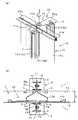
図1〜図4は、この発明の目地材およびその施工方法を構造物であるケーソンの目地部に適用した一実施の形態にかかり、図1は目地材の平面図および目地材の輸送状態の概略説明図、図2は施工状態の斜視図および平面図、図3はケーソンへの施工完了状態および地震時の変位状態の平面図、図4はケーソン全体への配置状態の平面図および断面図である。Hereinafter, embodiments of the present invention will be described in detail with reference to the drawings.
1 to 4 relate to an embodiment in which the joint material of the present invention and its construction method are applied to a joint part of a caisson that is a structure, and FIG. 1 is a plan view of the joint material and a transportation state of the joint material. FIG. 2 is a perspective view and a plan view of a construction state, FIG. 3 is a plan view of a caisson construction completion state and a displacement state at the time of an earthquake, and FIG. 4 is a plan view and a sectional view of a caisson arrangement state. It is.
この発明の目地材およびその施工方法は、例えば図4に示すような構造物であるケーソン1,1間の目地部2に適用され、この目地部2を遮水するために目地材10が施工される。なお、構造物としては、コンクリート製、鋼鉄製、これらを組み合わせたハイブリット製などのケーソンやL型ブロックなどであっても良い。 The joint material and its construction method of the present invention are applied to, for example, the
目地材10が設けられる構造物としてのケーソン1,1には、目地部2を挟んで対向する端面1a、1aにそれぞれ狭幅の開口部3a,3aが設けられるとともに、内部に空間3b,3bを備えた目地材取付溝3、3が上下方向に形成してある。この目地材取付溝3,3は、例えば図2(b)に示すように、ケーソン1の端面1aに横断面が矩形の凹部4を形成し、その開口を2枚の板材5で塞ぐようにして狭い幅の開口部3aと内部の空間3bを形成して目地材取付溝3,3としてある。さらに、この目地材取付溝3,3では、開口部3a,3aと目地材10との接触による損傷を防止するため、板材5の開口側端部に丸棒5aが溶接などで取り付けてあり、円弧面で接触するようにしてある。 The
なお、この目地材取付溝3は、開口部3aが狭幅で内部に空間3bが形成されるものであれば、その横断面形状は、矩形に限らず円形など他の形状であっても良く、開口部3aがケーソン1の端面1a上に位置し、空間3bがケーソン1内に配置される場合に限らず、鋼材などで構成した別体の目地材取付溝をケーソン1の端面1aから突き出すように取り付けるようにすることもできる。 As long as the
このような目地材取付溝3は、ケーソン1の端面1aの大きさにもよるが、図4の例では、海側に2箇所、廃棄物投入側になどの反対側に2箇所それぞれ設けられ、これにより、4箇所に目地材10が施工されるようにしてある。 Such a joint
なお、ケーソン1,1の対向する目地材取付溝3,3は、完全に直線状に対向させる必要はなく、目地材10の大きさなどによって異なるが、目地材を装着できる程度のずれが生じて対向する状態であっても良い。 The facing joint
このような対向するケーソン1,1の端面1a,1aの目地材取付溝3,3の間に取り付けられる目地材10は、例えば図1に示すように、両端部に目地材取付溝3に取り付けられる取付部11,11を備え、これら取付部11,11を連結して目地部2の変位に追従し得る伸縮部12が設けられ、ゴムや合成樹脂などの可撓性材料で作られてその可撓性および形状効果で変位に追従させるようにしてある。なお、目地材10には、必要に応じて可撓性材料の内部に補強材が入れられて外部を可撓性材料とした補強構造が採られたものが用いられる。 The
この目地材10では、伸縮部12がシート状の可撓性材料を環状に接続してその内部に中空部となる空間が形成される大環状部12aと、この中空部となる大環状部12aの中央部にシート状の可撓性材料の中央部を重ねて連結するとともに、両端部を重ねて環状とされた小環状部12bとで構成されている。また、この目地材10の小環状部12bの重ね合せ部分が一方の取付部11とされ、大環状部12aの反対側の中央部に可撓性材料のシートを重ねて連結し、その端部が外側に突き出したもう一方の取付部11としてある。そして、このような横断面形状の目地材10は、長手方向には、ケーソン1の高さに応じた必要な長さに形成され、複数枚の可撓性材料のシートを接着などで連結することで製造される。 In this
このような目地材10の取付部11,11には、目地材取付溝3に装着したときに開口部3aから抜け出すことがないように、抜け出し防止部材13が外側から取り付けてあり、装着時には、目地材10の取付部11,11の形状を保持するとともに、吊下げ重量を確保して施工性を向上する。 The
なお、この吊下げに必要な重量は、地上での実験によれば、目地材取付溝に目地材の取付部を挿入するときの抵抗値が10kgf/m程度であり、海中での施工では、目地材の比重を略海水と同程度とし、抜け出し防止材に用いる鋼材の比重を7.85とすれば、海水による浮力を考慮した必要重量Wは、10÷(8.85/7.85)で求められ、略11.2kgfとなることから、両側の重量を合わせてWを11kgf/m以上とすることが好ましい。 In addition, according to the experiment on the ground, the weight required for this suspension is a resistance value of about 10 kgf / m when inserting the joint portion of the joint material into the joint material mounting groove. If the specific gravity of the joint material is about the same as that of seawater and the specific gravity of the steel used for the escape prevention material is 7.85, the required weight W considering the buoyancy due to seawater is 10 ÷ (8.85 / 7.85) Therefore, it is preferable to set W to 11 kgf / m or more by adding the weights on both sides.
この抜け出し防止部材13は、取付部11に取り付けたときに外側に突き出して開口部3aから抜け出さないようにでき、しかも形状の保持と重量の確保の必要から型鋼材などの金属部材が好ましく用いられる。 This slip-out preventing
この目地材10では、溝型鋼で抜け出し防止部材13が構成され、溝部分を背中合わせとして取付部11,11の両外側から長手方向に沿って配置してボルトで締め付けて取り付けられる。 In this
このような溝型鋼で構成した抜け出し防止部材13を目地材10の取付部11,11の長手方向に取り付けると、目地材10を長手方向に巻回したり、折り畳むことができず、運搬などの取り扱いに支障をきたすことになる。 When the slip-
そこで、この目地材10では、抜け出し防止部材13を予め取り付ける先付け抜け出し防止部材(先付け型鋼材)13aと、運搬後、施工現場で取り付ける後付け抜け出し防止部材(後付け型鋼材)13bとで構成してある。そして、予め取り付ける先付け抜け出し防止部材(先付け型鋼材)13aを間隔をあけて目地材10の取付部11,11に取り付けることで、図1(b)に示すように、後付け抜け出し防止部材(後付け型鋼材)13bの取り付け部分を湾曲させることができ、折り畳んで運搬台上に載せることができ、必要に応じてスペーサなどを介して重ねられる。 In view of this, the
そして、運搬後、施工現場で後付け抜け出し防止部材(後付け型鋼材)13bを取り付ける場合には、予め取り付けた先付け抜け出し防止部材(先付け型鋼材)13aの間隔をあけた部分に配置して上下の先付け抜け出し防止部材(先付け型鋼材)13aとスポット溶接で連結したり、間隔より長い後付け抜け出し防止部材(後付け型鋼材)13bを重ねてボルトで締め付けて取り付けることで、直線状の形状を確保できるようにする。 And when carrying out the post-attachment prevention member (retrofitting type steel material) 13b at a construction site after transportation, it arrange | positions in the part which opened the space | interval of the pre-attached advance prevention member (pre-attachment type steel material) 13a, and attaches up and down. It is possible to secure a linear shape by connecting with a slip-out prevention member (pre-attached steel material) 13a by spot welding, or by attaching and attaching a post-attachment preventive member (retrofitting type steel material) 13b longer than the interval by tightening with bolts. To do.
次に、このような目地材10の施工方法について説明する。
目地部2を挟んで対向するケーソン1,1の目地材取付溝3,3の距離(通常は目地間隔Dに相当)に合わせて目地材10の取付部11,11を吊り上げることができるように、例えば図2(a)に示すように、吊り上げ治具20を用意する。Next, the construction method of such
The
この吊り上げ治具20は、略十字状の吊り上げ板21の一方の両端部21aに、目地材10の小環状部12bを引き伸ばして取付部11、11を目地間隔Dに合わせて支持するとともに、吊り上げ板21の直交するもう一方の両端部21bで伸縮部12の大環状部12aを目地部2に吊り下ろすことができるように押し潰して重ねた状態で支持する。 The lifting
こうして吊り上げ治具20を介して吊り上げた目地材10を吊り下ろし、両端部の取付部11,11が目地材取付溝3,3の空間3b、3b内に位置し、伸縮部12が開口部3a,3a間に位置するようにし、抜け出し防止部材13の重量を利用して吊り下ろすことで、目地材10の下端から装着していく。 The
そして、目地材1の先付け抜け出し防止部材(先付け型鋼材)13aの大部分を挿入した状態で、後付け抜け出し防止部材(後つけ型鋼材)13bを現場で取り付け、目地材10の取付部11,11の形状を直線状に保持するとともに、吊下げ重量を確保して吊下げることを繰り返し、目地材10を目地材取付溝3,3に予めつけてある天端マークまで装着する。 Then, in a state where most of the front-end slip-out preventing member (front-end type steel material) 13a of the
この後、吊下げ治具20を取り外し、目地材10の伸縮部12の大環状部12aの内側にアスファルトマスチックなどの中詰材14を充填して押し広げ、目地部2の両側に接する遮水状態とする(この中詰材14の充填は、充填後、ケーソン1,1の安定を待って補充する)。 After that, the suspending
そして、目地材10の取付部11,11が装着された目地材取付溝3,3の空間3bに膨張モルタルなどの充填材15を充填して固定する。
こうして、1箇所の目地材10の取付施工が完了する(図3(a)参照)。Then, the
In this way, the installation construction of one
この後、図4に示したように、2つの目地材10を隣接して設けた場合には、これら目地材10,10間にアスファルトマスチックなどの間詰材16を投入し、一層完全な遮水状態を確保するようにする。 Thereafter, as shown in FIG. 4, when two
こうして目地材10を施工した状態で、例えば地震などでケーソン1,1が変位して目地間隔Dが広がる場合には、図3(b)に示すように、目地材の小環状部12bが引き出されるように広がって遮水状態が維持される。 In the state where the
また、地震などでケーソン1,1が変位して目地間隔Dが広がると同時に前後にずれるようになる場合には、図3(c)に示すように、目地材10の小環状部12bが斜めに引き出されるように広がることで遮水状態が維持される。 In addition, when the
この目地材10およびその施工方法によれば、可撓性材料の伸縮部12の両端の取付部11,11の外側に抜け出し防止材13を設けたので、取付部11,11の外側の抜け出し防止材13で抜け出しを防止することができ、しかも癖のない装着形状を保持することができるとともに、装着時の重量を確保することもでき、施工性が向上する。 According to this
また、金属部材や型鋼材の抜け出し防止部材13により、可能性材料が外側に位置する場合に比べ、目地材取付溝3,3との摩擦を小さくして装着を容易にすることができる。 In addition, the metal member and the steel plate member
さらに、抜け出し防止部材13を外側に配置することで、運搬後、装着前に後付け型鋼材13bの取り付けも可能となり、運搬性や取扱い性に優れる。 Furthermore, by disposing the pull-
この目地材10およびその施工方法によれば、抜け出し防止部材13を、取付部11,11を挟む両側に対称に取り付けるようにしたので、目地材取付溝3,3への装着の際に前後・左右のバランスを保って吊下げることができ、一層装着など施工を安定した状態で円滑に行うことができる。 According to this
さらに、この目地材10およびその施工方法では、目地材10の伸縮部12に、中空部としての大環状部13aを設けて中詰材を充填するようにしたので、中詰材14で膨らませた中空部である大環状部13aで目地部2の遮水性を向上することができる。 Furthermore, in this
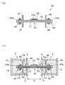
次に、この発明の目地材およびその施工方法の他の一実施の形態について、図5により説明する。
この目地材30は、ゴムや合成樹脂のシート状の膜部材を多重構造として構成したものであり、受圧膜シート31と、その外側の受圧膜シートより広幅で中間部に折り畳み部32aを備えるとともに、両端部に膨らんだ膨出部32bが形成された変位追従膜シート32と、さらに外側の保護用のゴムなどの保護膜シート33とを重ね合わせて構成されている。そして、受圧膜シート31および変位追従膜シート32は、補強材を挟んだ補強構造とされ、両端部の取付部34,34部分は、幅方向に2枚、長さ方向に2枚の補強材が入れられた4プライ構造とされ、中間部分の伸縮部35は2枚の補強材が入れられた2プライ構造としてある。Next, another embodiment of the joint material and its construction method according to the present invention will be described with reference to FIG.
This
このような目地材30の両端の取付部34,34には、抜け出し防止材36として、山型鋼が取付部34を挟んで両側に配置され、山型鋼の中央部側が直角に突き出すようにしてボルトで締め付けてある。 In the mounting
この抜け出し防止部材36も、すでに説明したように、長手方向には、一定の間隔をあけて予め取り付ける先付け抜け出し防止部材と運搬後装着前に取り付ける後付け抜け出し防止部材とで構成することで、長手方向に折り畳むことができるようにし、これにより、運搬性や取扱い性を確保する。 As described above, this slip-out preventing
このような目地材30の目地材取付溝3,3への装着は、すでに説明した目地材10と同様にして行われる。 The mounting of the
なお、この目地材30では、取付部34,34および抜け出し防止部材36の取付間隔は一定であり、目地材10のように小環状部12bの引き出し量で変えることができないため、そのまま目地材取付溝3,3の空間3b、3bに吊り下ろして装着する。 In this
したがって、抜け出し防止部材36の山型鋼が、たとえば図5(b)に示すように、開口部3aと必ずしも当接した状態とならないが、充填材15を充填することで固定され、遮水性や変位に対する追従性などに何ら支障はない。 Therefore, the chevron steel of the slip-
このような目地材30およびその施工方法によってもすでに説明した目地材10およびその施工方法と同様の作用効果を奏する。 The
なお、上記各実施の形態では、2つの異なる形状の目地材を例に説明したが、目地材の形状は両端部に取付部を備え、これらをつないで変位に追従できる部分が設けられるものであれば、どのような形状や材料であっても良い。 In each of the above embodiments, the joint material having two different shapes has been described as an example. However, the shape of the joint material is provided with a mounting portion at both ends, and a portion that can follow these displacements by connecting them is provided. Any shape or material may be used.
また、上記実施の形態では、ケーソンの目地に適用する場合で説明したが、ケーソンに限らず他の構造物の目地にも同様に適用することができる。 Moreover, in the said embodiment, although demonstrated in the case of applying to the joint of a caisson, it can apply similarly to the joint of not only a caisson but another structure.
1 ケーソン(構造物)
1a 端面
2 目地部
3,3 目地材取付溝
3a,3a 開口部
3b,3b 空間
4 凹部
5 板材
5a 丸棒
10 目地材
11 取付部
12 伸縮部
12a 大環状部(中空部)
12b 小環状部
13 抜け出し防止部材
13a 先付け抜け出し防止部材(先付け型鋼材)
13b 後付け抜け出し防止部材(後付け型鋼材)
14 中詰材
15 充填材
16 間詰材
20 吊り上げ治具
30 目地材
31 受圧膜シート
32 変位追従膜シート
33 保護膜シート
34,34 取付部
35 伸縮部
36 抜け出し防止部材
D 目地間隔
1 Caisson (structure)
DESCRIPTION OF
12b Small
13b Retrofitting prevention member (retrofitting type steel)
14
Claims (7)
Translated fromJapaneseこの目地材の両端部の前記取付部の外側に、前記目地材取付溝の前記開口部からの抜け出しを防止するとともに、装着時の吊下げ重量を確保する抜け出し防止部材を設ける一方、この抜け出し防止部材を、前記取付部の外側に当て間隔をあけて予め取り付けられる先付け型鋼材と、前記目地材取付溝への装着時に前記先付け型鋼材の間隔に取り付ける後付け型鋼材とで構成したことを特徴とする目地材。Mounting portions of the respective end portions are mounted in joint material mounting grooves provided in the vertical direction of the opposing surface of the structure facing each other across the joint portion and facing the narrow opening portion, and between the opening portions. A joint material provided with a stretchable portion of a flexible material capable of absorbing the displacement of the joint portion in the arranged intermediate portion,
Outside of the mounting portion of the both end portions of the joint member,while it is possible to prevent the exit from the opening of the joint member mounting groove,Ru provided preventing member exit to ensure the hanging weight atattachment, the exit The prevention member is composed of a pre-attached steel material that is attached in advance to the outside of the attachment portion with a gap, and a post-installation steel material that is attached to the space of the pre-attached steel material when installed in the joint material mounting groove. Joint material.
前記目地材の両端部の前記取付部に設け前記目地材取付溝の前記開口部からの抜け出しを防止するとともに、装着時の吊下げ重量を確保する抜け出し防止部材を前記取付部の外側に当て間隔をあけて予め取り付けられる先付け型鋼材と、前記目地材取付溝への装着時に前記先付け型鋼材の間隔に取り付ける後付け型鋼材とで構成し、
前記先付け型鋼材の抜け出し防止部材が取り付けられた前記目地材を前記目地材取付溝に吊り下ろした後、前記間隔に後付け型鋼材の抜け出し防止部材を取り付けて吊り下ろすことを繰り返し、次いで前記中間部を前記目地材取付溝の開口部間に位置させて装着固定するようにしたことを特徴とする目地材の施工方法。A joint material mounting groove is provided in which the narrow opening is opposed in the vertical direction of the opposing surface of the structure facing the joint part, and the attachment part of each end is mounted on the joint material mounting groove, It is a construction method of a joint material to which a middle part is disposed between the openings and is attached by attaching a joint material composed of a stretchable portion of a flexible material capable of absorbing the displacement of the joint part,
Provided at the attachment portionat both ends of the joint material, the joint material mounting groove is prevented from slipping out from the opening, and an escape prevention member that secures a hanging weight at the time ofmounting is applied to the outside of the mounting portion. A pre-attached steel material that is attached in advance with an opening, and a post-attached steel material that is attached to the space between the pre-attached steel materials when installed in the joint material mounting groove,
Aftersaid tipping-type steel exit prevention memberis Kudaro hanging on the joint member mounting groove the joint member attachedrepeatedly that down hanging attach the escape preventing member retrofitted type steel into the gap, then the intermediate portion Is installed between the openings of the joint material mounting groove and fixed.
Priority Applications (1)
| Application Number | Priority Date | Filing Date | Title |
|---|---|---|---|
| JP2006035067AJP4256396B2 (en) | 2006-02-13 | 2006-02-13 | Joint material and its construction method |
Applications Claiming Priority (1)
| Application Number | Priority Date | Filing Date | Title |
|---|---|---|---|
| JP2006035067AJP4256396B2 (en) | 2006-02-13 | 2006-02-13 | Joint material and its construction method |
Publications (2)
| Publication Number | Publication Date |
|---|---|
| JP2007211545A JP2007211545A (en) | 2007-08-23 |
| JP4256396B2true JP4256396B2 (en) | 2009-04-22 |
Family
ID=38490228
Family Applications (1)
| Application Number | Title | Priority Date | Filing Date |
|---|---|---|---|
| JP2006035067AActiveJP4256396B2 (en) | 2006-02-13 | 2006-02-13 | Joint material and its construction method |
Country Status (1)
| Country | Link |
|---|---|
| JP (1) | JP4256396B2 (en) |
Families Citing this family (5)
| Publication number | Priority date | Publication date | Assignee | Title |
|---|---|---|---|---|
| EP2698937B1 (en) | 2007-06-19 | 2015-08-19 | Panasonic Intellectual Property Corporation of America | Channel arrangement reception circuit for radio communication |
| JP5736584B2 (en)* | 2010-09-07 | 2015-06-17 | 西武ポリマ化成株式会社 | Joint material |
| JP5940593B2 (en)* | 2014-06-20 | 2016-06-29 | 西武ポリマ化成株式会社 | Joint material and its construction method |
| JP6700066B2 (en)* | 2016-02-26 | 2020-05-27 | 西武ポリマ化成株式会社 | Impermeable structure at joints between structures |
| JP6647913B2 (en)* | 2016-02-26 | 2020-02-14 | 西武ポリマ化成株式会社 | Water blocking structure of joint material mounting groove |
- 2006
- 2006-02-13JPJP2006035067Apatent/JP4256396B2/enactiveActive
Also Published As
| Publication number | Publication date |
|---|---|
| JP2007211545A (en) | 2007-08-23 |
Similar Documents
| Publication | Publication Date | Title |
|---|---|---|
| JP4256396B2 (en) | Joint material and its construction method | |
| AU2013342824B2 (en) | Method for constructing cylindrical tank | |
| US9970171B2 (en) | Passive grout seal | |
| US20050254905A1 (en) | Steel-pipe sheet pile and coupling structure of steel-pipe sheet piles | |
| JP6260932B2 (en) | Tube for preventing flooding and its bundling structure | |
| JP2008008090A (en) | Strip-shaped steel plate for reinforcing column body | |
| KR101698916B1 (en) | method of making temporary water protection wall using apparatus for temporary water protection | |
| JP2012246670A (en) | Uplift pressure-resisting underground structure | |
| JP2014218847A (en) | Temporary cofferdam wall | |
| JP7039856B2 (en) | Construction method of reinforcing bar cage for piles, piles and geothermal heat exchange piping | |
| JP5928722B2 (en) | Water stop structure | |
| JP4179415B2 (en) | Joining method and joining member of jacket structure and pile | |
| JP4437181B2 (en) | Water storage device | |
| US20080317551A1 (en) | Evaporation retarding cover | |
| JP4441240B2 (en) | Sheet connection structure | |
| JP6436712B2 (en) | Joint material mounting structure | |
| JP4927766B2 (en) | Joint structure for upper and lower split caisson and its construction method | |
| JP7008008B2 (en) | How to build piers, piers | |
| AU2017202329A1 (en) | Improvements in Flood Barriers | |
| JP2020197018A (en) | Improved base structure, and construction method of improved base | |
| JP2012202042A (en) | Combination steel sheet pile having drainage function and wall body structure using the steel sheet pile | |
| KR200458388Y1 (en) | Protective structure for easy impact mitigation | |
| JP6447669B2 (en) | Seawall and construction method of seawall | |
| JP5940593B2 (en) | Joint material and its construction method | |
| JP2008223331A (en) | Rubber back-filling material |
Legal Events
| Date | Code | Title | Description |
|---|---|---|---|
| A977 | Report on retrieval | Free format text:JAPANESE INTERMEDIATE CODE: A971007 Effective date:20080522 | |
| A131 | Notification of reasons for refusal | Free format text:JAPANESE INTERMEDIATE CODE: A131 Effective date:20081030 | |
| A521 | Request for written amendment filed | Free format text:JAPANESE INTERMEDIATE CODE: A523 Effective date:20081225 | |
| TRDD | Decision of grant or rejection written | ||
| A01 | Written decision to grant a patent or to grant a registration (utility model) | Free format text:JAPANESE INTERMEDIATE CODE: A01 Effective date:20090127 | |
| A01 | Written decision to grant a patent or to grant a registration (utility model) | Free format text:JAPANESE INTERMEDIATE CODE: A01 | |
| A61 | First payment of annual fees (during grant procedure) | Free format text:JAPANESE INTERMEDIATE CODE: A61 Effective date:20090129 | |
| FPAY | Renewal fee payment (event date is renewal date of database) | Free format text:PAYMENT UNTIL: 20120206 Year of fee payment:3 | |
| R150 | Certificate of patent or registration of utility model | Ref document number:4256396 Country of ref document:JP Free format text:JAPANESE INTERMEDIATE CODE: R150 Free format text:JAPANESE INTERMEDIATE CODE: R150 | |
| FPAY | Renewal fee payment (event date is renewal date of database) | Free format text:PAYMENT UNTIL: 20120206 Year of fee payment:3 | |
| FPAY | Renewal fee payment (event date is renewal date of database) | Free format text:PAYMENT UNTIL: 20120206 Year of fee payment:3 | |
| S531 | Written request for registration of change of domicile | Free format text:JAPANESE INTERMEDIATE CODE: R313531 | |
| FPAY | Renewal fee payment (event date is renewal date of database) | Free format text:PAYMENT UNTIL: 20120206 Year of fee payment:3 | |
| R350 | Written notification of registration of transfer | Free format text:JAPANESE INTERMEDIATE CODE: R350 | |
| FPAY | Renewal fee payment (event date is renewal date of database) | Free format text:PAYMENT UNTIL: 20120206 Year of fee payment:3 | |
| FPAY | Renewal fee payment (event date is renewal date of database) | Free format text:PAYMENT UNTIL: 20120206 Year of fee payment:3 | |
| FPAY | Renewal fee payment (event date is renewal date of database) | Free format text:PAYMENT UNTIL: 20130206 Year of fee payment:4 | |
| R250 | Receipt of annual fees | Free format text:JAPANESE INTERMEDIATE CODE: R250 | |
| FPAY | Renewal fee payment (event date is renewal date of database) | Free format text:PAYMENT UNTIL: 20130206 Year of fee payment:4 | |
| R250 | Receipt of annual fees | Free format text:JAPANESE INTERMEDIATE CODE: R250 | |
| R250 | Receipt of annual fees | Free format text:JAPANESE INTERMEDIATE CODE: R250 | |
| R250 | Receipt of annual fees | Free format text:JAPANESE INTERMEDIATE CODE: R250 | |
| R250 | Receipt of annual fees | Free format text:JAPANESE INTERMEDIATE CODE: R250 | |
| R250 | Receipt of annual fees | Free format text:JAPANESE INTERMEDIATE CODE: R250 | |
| R250 | Receipt of annual fees | Free format text:JAPANESE INTERMEDIATE CODE: R250 | |
| R250 | Receipt of annual fees | Free format text:JAPANESE INTERMEDIATE CODE: R250 | |
| R250 | Receipt of annual fees | Free format text:JAPANESE INTERMEDIATE CODE: R250 | |
| R250 | Receipt of annual fees | Free format text:JAPANESE INTERMEDIATE CODE: R250 | |
| R250 | Receipt of annual fees | Free format text:JAPANESE INTERMEDIATE CODE: R250 | |
| R250 | Receipt of annual fees | Free format text:JAPANESE INTERMEDIATE CODE: R250 | |
| R250 | Receipt of annual fees | Free format text:JAPANESE INTERMEDIATE CODE: R250 | |
| R250 | Receipt of annual fees | Free format text:JAPANESE INTERMEDIATE CODE: R250 |