JP4255090B2 - Numerical control device for machine tools - Google Patents
Numerical control device for machine toolsDownload PDFInfo
- Publication number
- JP4255090B2 JP4255090B2JP05021098AJP5021098AJP4255090B2JP 4255090 B2JP4255090 B2JP 4255090B2JP 05021098 AJP05021098 AJP 05021098AJP 5021098 AJP5021098 AJP 5021098AJP 4255090 B2JP4255090 B2JP 4255090B2
- Authority
- JP
- Japan
- Prior art keywords
- input
- control unit
- data
- unit
- output
- Prior art date
- Legal status (The legal status is an assumption and is not a legal conclusion. Google has not performed a legal analysis and makes no representation as to the accuracy of the status listed.)
- Expired - Fee Related
Links
Images


Landscapes
- Numerical Control (AREA)
Description
Translated fromJapanese【0001】
【発明の属する技術分野】
本発明は工作機械の数値制御装置に関し、特に、工作機械の補助機能に関する制御プログラムデータやパラメータデータ等のデータをユーザサイドにおいて入出力可能にした数値制御装置に関する。
【0002】
【従来の技術】
従来の数値制御装置の一例を図3に示す。尚、図3は当該数値制御装置の概略構成を示したブロック図である。
【0003】
同図に示すように、この数値制御装置1は、工作機械の送り駆動系等、数値制御の対象となる駆動(機能)部分を制御する数値制御部2と、オペレータの安全或いは機械保護等のための各種インターロックに関する制御や主軸,マガジン,自動工具交換装置(ATC),自動パレット交換装置(APC),刃物台の制御等、工作機械の基本的な機能部分の制御、並びに、被加工物(以下、「ワーク」という)や加工工程に応じて工作機械に装備される治具,切削油供給装置,切粉処理装置,ワークの供給排出装置等、工作機械の補助的な機能部分の制御を行うPMCシステム部10と、加工プログラム等のデータを入出力する入出力手段7と、前記数値制御部2,PMCシステム部10及び入出力手段7をそれぞれ相互に接続せしめるバスシステム8とからなる。尚、前記入出力手段7は、CRT,MDI及び外部入出力機器などからなるものであり、入出力インターフェース9を介して前記バスシステム8に接続している。而して、前記数値制御部2及びPMCシステム部10に格納されたデータがCRTに表示され、MDIにより数値制御部2及びPMCシステム部10に格納されたデータを変更することができ、また、外部入出力機器から数値制御部2及びPMCシステム部10に所定のデータを一括して入力でき、逆に数値制御部2及びPMCシステム部10に格納されたデータを外部入出力機器に一括して出力できるようになっている。
【0004】
また、前記数値制御部2は、加工プログラムを格納する加工プログラムメモリ部6と、マシンセットアップデータ,システムパラメータ等のデータを格納するデータメモリ部5と、加工プログラムに従って処理を実行し、サーボデータ等を算出するCPU4と、前記加工プログラムメモリ部6及びデータメモリ部5へのデータの入出力、並びに前記CPU4における処理をコントロールするNCシステムコントロール部3とからなる。そして、前記バスシステム8及び入出力インターフェース9を介して数値制御部2からの制御信号が工作機械19に出力され、逆に工作機械19からの信号が同じく前記バスシステム8及び入出力インターフェース9を介して数値制御部2に入力される。
【0005】
また、前記PMCシステム部10は、シーケンスプログラムが格納されたプログラムメモリ部12と、工具本数,切削油供給時間等のデータが格納されたデータメモリ部13と、シーケンスプログラムに従って処理を実行するCPU14と、前記プログラムメモリ部12及びデータメモリ部13へのデータの入出力、並びに前記CPU14における処理をコントロールするシステムコントロール部11と、これらプログラムメモリ部12,データメモリ部13及びCPU14をそれぞれ相互に接続せしめるバスシステム16と、入出力インターフェース15とからなり、この入出力インターフェース15を介してPMCシステム部10からの制御信号が工作機械19に出力され、逆に工作機械19からの信号がPMCシステム部10に入力される。
【0006】
斯くして、この数値制御装置1によれば、前記数値制御部2とPMCシステム部10とがバスシステム8を介して相互に信号のやりとりを行いながら、それぞれ処理を実行し、工作機械19の数値制御対象機能部,基本機能部及び補助機能部の作動がそれぞれ制御される。
【0007】
この他に、図4に示した数値制御装置も従来存在する。同図に示すように、この数値制御装置20は、主制御装置20aと副制御装置20bとから構成されるもので、上述したPMCシステム部10を基本機能制御に係る基本機能システム部21と補助機能に係る補助機能システム部31とに分割し、且つシステムコントロール部22,プログラムメモリ部23,データメモリ部24,CPU25,バスシステム27及び入出力インターフェース26からなる基本機能システム部21を前記主制御装置20a内に設け、システムコントロール部32,プログラムメモリ部33,データメモリ部34,CPU35,バスシステム37及び入出力インターフェース36からなる補助機能システム部31を前記副制御装置20b内に設けた点が、上述の数値制御装置1と異なり、他の構成、即ち、数値制御部2,入出力手段7,バスシステム8及び入出力インターフェース9については上述の数値制御装置1と同様である。従って、同じ構成部分については、図4において同じ符号を付している。
【0008】
尚、前記基本機能システム部21と補助機能システム部31とは、入出力インターフェース26,36を介して相互に接続している。また、入出力インターフェース26を介して基本機能システム部21からの制御信号が工作機械19に出力され、同インターフェース26を介して逆に工作機械19からの信号が基本機能システム部21に入力されるようになっている。また、入出力インターフェース36を介して補助機能システム部31からの制御信号が工作機械19に出力され、同インターフェース36を介して逆に工作機械19からの信号が補助機能システム部31に入力されるようになっている。
【0009】
また、副制御装置20bには前記入出力手段7とは別の入出力手段38が接続している。この入出力手段38も前記入出力手段7と同様に、CRT,MDI及び外部入出力機器などからなり、入出力インターフェース9を介して補助機能システム部31に格納されたデータがCRTに表示され、MDIにより補助機能システム部31に格納されたデータを変更することができ、また、外部入出力機器から補助機能システム部31に所定のデータを一括して入力でき、逆に補助機能システム部31に格納されたデータを外部入出力機器に一括して出力できるようになっている。
【0010】
斯くして、この数値制御装置20によっても前記数値制御装置1におけると同様に、数値制御部2と基本機能システム部21とが相互に信号のやりとりを行いながら、また、基本機能システム部21と補助機能システム部31とが相互に信号のやりとりを行いながら、それぞれ処理を実行し、工作機械19の数値制御対象機能部,基本機能部及び補助機能部の作動がそれぞれ制御される。
【0011】
【発明が解決しようとする課題】
ところで、上述の数値制御装置1において、ワークの供給排出装置を追加,変更した場合等には、前記PMCシステム部10のプログラムメモリ部12に格納したデータ(所謂、シーケンスプログラムやパラメータデータ)及びデータメモリ部13に格納したデータを修正する必要を生じる。
【0012】
この場合、上述したインターロックに関係するデータや機械保護に関係するデータ等、工作機械の基本的な機能に関するデータをもユーザが自由に修正することができるとすると、その機能を有効に確保することができなくなるおそれがあるため、従来は、ユーザサイドにおいて当然しなければならない加工プログラム及びデータメモリ部5に格納されたこれに関連する一部のデータの入出力についてのみユーザサイドに解放し、その他のデータの入出力はメーカサイドにおいてのみ可能となるような手段を講じていた。具体的には、入出力要求信号(例えば、パスワード)をユーザサイドとメーカサイドとで区別して設定し、入出力手段7から入力された入出力要求信号を前記NCシステムコントロール部3において確認し、入出力要求信号がユーザサイドのものであれば前記加工プログラムメモリ部6に格納されたデータ及びデータメモリ部5に格納された一部のデータについてのみ入出力可能となるように、一方、入出力要求信号がメーカサイドのものであれば数値制御装置1内の全てのデータを入出力可能となるように、当該NCシステムコントロール部3により制御していた。換言すれば、従来は、数値制御装置1内に格納されたデータの内、ユーザサイドに解放したデータ以外のデータを修正する場合には、メーカサイドにおいて行うようにしていた。尚、上記「入出力」はデータの変更を含む概念であり、以下、「入出力」というときは、データの入出力及びデータの変更の双方を含むものとしてこれを使用している。
【0013】
ところが、修正が必要となるデータの中には、必ずしもメーカサイドで修正する必要のない、工作機械の補助的な機能に関するものもあり、これらを含めて全てのデータの修正をメーカサイドにおいて行うものとすると、タイムリーな修正を行うことができず、また、そのコストが高いものとなるという問題があった。特に、上述した数値制御装置1におけるように、工作機械の基本機能と補助機能とを1つのシーケンスプログラムにより制御するようにすると、当該シーケンスプログラムを修正するに当たり、膨大な制御図面を修正する必要があり、その修正作業に膨大な時間を要する。また、メーカサイドとユーザサイドとでその修正可能なデータを明確に区分けすることができないため、ユーザサイドに解放可能な前記補助機能に関するデータであってもこれをユーザサイドに解放できないという問題もあった。
【0014】
一方、図4に示した数値制御装置20においては、前記補助機能に関する制御を行う補助機能システム部31を、前記基本機能に関する制御を行う基本機能システム部21とは別個に設けるとともに、専用の入出力手段38により前記システム部31内のデータを修正可能に設けているので、補助機能に関するデータの修正をユーザサイドで行うことができるが、専用の入出力手段38が必要となることから設備的にコストが高くなるという問題がある。
【0015】
本発明は以上の実情に鑑みなされたものであって、低コストで補助機能に関するデータをユーザサイドで編集することができるようにし、また、ユーザサイドが補助機能に関するデータを編集する際に、工作機械の基本機能を損なうことのないようにした数値制御装置の提供を目的とする。
【0016】
【課題を解決するための手段及びその効果】
上記目的を達成するための本発明の請求項1に係る発明は、工作機械の送り駆動系を少なくとも数値制御する数値制御部と、オペレータの安全或いは機械保護のためのインターロックに関する制御及び主軸の制御を少なくとも行う基本機能制御部と、切削油供給装置を少なくとも制御する補助機能制御部と、データを入出力する入出力部とを備え、前記数値制御部は、前記送り駆動系を数値制御するためのデータが格納された、読み書き可能な記憶装置からなる第1データ記憶部を、前記基本機能制御部は、前記インターロックに関する制御及び主軸の制御を行うためのデータが格納された、読み書き可能な記憶装置からなる第2データ記憶部を、前記補助機能制御部は、前記切削油供給装置を制御するためのデータが格納された、読み書き可能な記憶装置からなる第3データ記憶部をそれぞれ有する数値制御装置において、
前記数値制御部,基本機能制御部及び補助機能制御部がそれぞれ別個に並設され、且つ該数値制御部,基本機能制御部及び補助機能制御部並びに前記入出力部がバスシステムを介してそれぞれ相互に接続されてなり、
前記入出力部から入力された入出力要求信号を確認し、確認した入出力要求信号に応じて、前記数値制御部,基本機能制御部及び補助機能制御部に対する、前記第1データ記憶部,第2データ記憶部及び第3データ記憶部内に格納されたデータの入出力をそれぞれ制御する手段であって、前記バスシステムに接続された要求信号確認手段を備え、
前記要求信号確認手段は、前記確認した入出力要求信号が、前記基本機能制御部及び補助機能制御部の両方に対するデータの入出力が許可されているものである場合には、該基本機能制御部及び補助機能制御部の両方に対してデータを入出力可能とし、前記確認した入出力要求信号が、前記基本機能制御部及び補助機能制御部の内、前記補助機能制御部のみに対するデータの入出力が許可されているものである場合には、前記基本機能制御部及び補助機能制御部の内、前記補助機能制御部に対してのみデータを入出力可能とするように構成されてなることを特徴とするものである。
【0017】
尚、この発明において、前記数値制御部は、上述した工作機械の送り駆動系等、数値制御の対象となる機能部分を制御するものであり、前記基本機能制御部は、上述したオペレータの安全或いは機械保護等のための各種インターロックに関する部分や主軸の他、マガジン、自動工具交換装置(ATC)、自動パレット交換装置(APC)、刃物台等、工作機械の基本的な機能部分を制御するものであり、前記補助機能制御部は、上述した切削油供給装置の他、ワークや加工工程に応じて工作機械に装備される治具、切粉処理装置、ワークの供給排出装置等、工作機械の補助的な機能部分を制御するものである。
【0018】
この発明によれば、加工プログラム,パラメータデータ及びシーケンスプログラム等の諸データを入出力部から数値制御装置に入出力するに際し、当該データの入出力が前記要求信号確認手段により制御される。即ち、要求信号確認手段は、前記入出力部から入力された入出力要求信号を確認し、確認した入出力要求信号に応じて、前記数値制御部,基本機能制御部及び補助機能制御部に対する、前記第1データ記憶部,第2データ記憶部及び第3データ記憶部内に格納されたデータの入出力をそれぞれ制御するとともに、前記確認した入出力要求信号が、前記基本機能制御部及び補助機能制御部の両方に対するデータの入出力が許可されているものである場合には、該基本機能制御部及び補助機能制御部の両方に対してデータを入出力可能とし、前記確認した入出力要求信号が、前記基本機能制御部及び補助機能制御部の内、前記補助機能制御部のみに対するデータの入出力が許可されているものである場合には、前記基本機能制御部及び補助機能制御部の内、前記補助機能制御部に対してのみデータを入出力可能とする。
【0019】
従って、例えば、メーカサイドとユーザサイドとで入出力要求信号を異なったものに設定し、メーカサイドの入出力要求信号が入力された場合には数値制御装置内で扱う全てのデータについて入出力可能となるように制御する一方、ユーザサイドの入出力要求信号が入力された場合には、数値制御装置内の特定のデータについて入出力可能となるように制御することができる。これにより、ユーザサイドに基本機能制御部に係わるデータの入出力を認めないで、補助機能制御部に係わるデータのみについて入出力可能となるようにすることができる。
【0020】
斯くして本発明によれば、工作機械の基本的な機能に係わるデータの入出力についてはユーザサイドに禁止する一方、工作機械の補助的な機能に係わるデータの入出力についてはユーザサイドにおいてこれを独自に行うことができるようにすることができるので、工作機械の基本的な機能を損なうことなく補助機能の追加や修正をユーザサイドで行うことができ、この追加,修正をタイムリーにしかも短期間に、また、低コストで行うことができる。
【0021】
また、基本機能制御部と補助機能制御部とを別個に設けているので、それぞれに対応した制御図面を明確に区分けすることができ、その管理を容易に行うことができる。また、これらを修正する場合には、基本機能制御部と補助機能制御部とをそれぞれ個別に修正すれば足り、これらを併合して設けていた従来に比べてその修正量が少なく、修正時間も短くて足りるため、修正に要する費用を従来に比べて安価なものとすることができる。
【0022】
また、別個に設けた基本機能制御部と補助機能制御部とを一つのバスシステムを介して前記要求信号確認手段及び入出力部に接続しているので、基本機能制御部及び補助機能制御部に対するデータの入出力を一つの入出力部により行うことができ、補助機能制御部に対する専用の入出力部は特に必要なく、設備面で低コスト化を図ることができる。
【0023】
【発明の実施の形態】
以下、本発明の具体的な実施形態について添付図面に基づき説明する。
【0024】
(第1の実施形態)
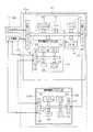
まず、本発明の第1の実施形態について図1に基づき説明する。図1は本実施形態に係る数値制御装置の概略構成を示すブロック図である。
【0025】
図1に示すように、この実施形態に係る数値制御装置40は上述の図3に示した数値制御装置1及び図4に示した数値制御装置20を改良したものであり、数値制御部41と、基本機能システム部21と、補助機能システム部31と、入出力手段7と、前記数値制御部41,基本機能システム部21,補助機能システム部31及び入出力手段7をそれぞれ相互に接続せしめるバスシステム8と、前記入出力手段7とバスシステム8との間に設けた入出力インターフェース9とからなるものである。
【0026】
尚、前記入出力手段7,バスシステム8及び入出力インターフェース9は上述の数値制御装置1及び数値制御装置20におけるものと同じ構成であり、また、基本機能システム部21及び補助機能システム部31は上述の数値制御装置20におけるものと同じ構成であるので、同一の符号を付してその詳しい説明を省略する。また、基本機能システム部21のプログラムメモリ部23及びデータメモリ部24が、特許請求の範囲における基本機能制御部の第2データ記憶部に相当し、補助機能システム部31のプログラムメモリ部33及びデータメモリ部34が、特許請求の範囲における補助機能制御部の第3データ記憶部に相当する。
【0027】
また、数値制御部41はNCシステムコントロール部42,CPU4,データメモリ部5及び加工プログラムメモリ部6とからなるが、CPU4,データメモリ部5及び加工プログラムメモリ部6については上述の数値制御装置1及び数値制御装置20におけるものと同じ構成であり、従ってこれについても同一の符号を付してその詳しい説明を省略する。尚、数値制御部41のデータメモリ部5及び加工プログラムメモリ部6が、特許請求の範囲における数値制御部の第1データ記憶部に相当する。
【0028】
上述したように、前記数値制御部41は、従来の数値制御部2におけるNCシステムコントロール部3に代えて、これと機能の異なるNCシステムコントロール部42を備えたものであり、このNCシステムコントロール部42は、入出力手段7から入力された入出力要求信号を確認し、確認した入出力要求信号に応じて、数値制御部41,基本機能システム部21及び補助機能システム部31に対する、データメモリ部5,24,34、加工プログラムメモリ部6及びプログラムメモリ部23,33に格納されたデータの入出力をそれぞれ制御する。具体的には、前記入出力手段7から入力された入出力要求信号が、予め設定されたユーザサイドのものであれば前記加工プログラムメモリ部6並びに補助機能システム部31のプログラムメモリ部33及びデータメモリ部34に対してのみデータ入出力可能となるように、メーカサイドのものであれば数値制御部41のデータメモリ部5及び加工プログラムメモリ部6、基本機能システム部21のプログラムメモリ部23及びデータメモリ部24、並びに補助機能システム部31のプログラムメモリ部33及びデータメモリ部34に対してデータ入出力可能となるように当該データの入出力を制御するようになっている。
【0029】
斯くしてこの数値制御装置40によれば、加工プログラム,パラメータデータ及びシーケンスプログラム等の諸データを入出力手段7から当該数値制御装置40に入出力するに際し、当該データの入出力が前記NCシステムコントロール部42によって制御される。具体的には、前記入出力手段7から入力された入出力要求信号がユーザサイドのものであれば、前記加工プログラムメモリ部6及び補助機能システム部31に対してデータが入出力可能となるように、入出力要求信号がメーカサイドのものであれば数値制御部41,基本機能システム部21及び補助機能システム部31に対して全てのデータが入出力可能となるように、前記NCシステムコントロール部42によって当該データの入出力が制御される。
【0030】
このように、この数値制御装置40によれば、基本機能システム部21と補助機能システム部31とを別個に設け、これらをバスシステム8を介して入出力手段7と接続するとともに、NCシステムコントロール部42により、入出力要求信号に応じてデータの入出力を制御しているので、基本機能システム部21に係わるデータを除いた、補助機能システム部31に係わるデータのみについてその入出力をユーザサイドに解放することができる。これにより、補助機能の追加や修正を、工作機械の基本的な機能を損なうことなくユーザサイドで自由に行うことができ、タイムリーにしかも短期間に、また、低コストで行うことができる。
【0031】
また、基本機能システム部21と補助機能システム部31とを別個に設けていることから、それぞれに対応した制御図面を明確に区分けすることができ、その管理が容易となるとともに、これらを修正する場合には、基本機能システム部21と補助機能システム部31とについてそれぞれ個別に修正すれば足り、これらを併合して設けていた従来に比べてその修正量が少なく、修正時間も短くて足りるため、修正に要する費用を従来に比べて安価なものとすることができる。
【0032】
(第2の実施形態)
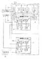
次に、本発明の第2の実施形態について図2に基づき説明する。図2は本実施形態に係る数値制御装置の概略構成を示すブロック図である。
【0033】
図2に示すように、この実施形態に係る数値制御装置55は上述の図1に示した数値制御装置40を改良し、図4に示した数値制御装置20におけると同様に、補助機能システム部56を副制御装置20b内に設けて構成したものである。従って、上述の数値制御装置40及び数値制御装置20と同じ構成について同一の符号を付してその詳しい説明を省略する。
【0034】
図2に示すように、この数値制御装置55は、前記バスシステム8に接続した入出力インターフェース47を主制御装置20a内に設ける一方、バスシステム37に接続した入出力インターフェース57を補助機能システム部56内に設けるとともに、前記入出力インターフェース47と入出力インターフェース57とを接続したものとして構成され、前記NCシステムコントロール部42による制御の下、入出力インターフェース9,バスシステム8,入出力インターフェース47及び入出力インターフェース57を介して入出力手段7から補助機能システム部56にデータが入力され、逆に補助機能システム部56から入出力手段7にデータが出力されるようになっている。
【0035】
斯くして、この数値制御装置55によれば、別々の装置として設けた数値制御部41及び基本機能システム部21と補助機能システム部56とを一つのバスシステム8を介して前記入出力手段7に接続せしめているので、数値制御部41及び基本機能システム部21と補助機能システム部56に対するデータの入出力を一つの入出力手段7により行うことができ、別装置として設けた補助機能システム部56についても専用的な入出力装置が特に必要なく、設備的に低コストにすることができる。
【0036】
以上、本発明の実施形態について説明したが、本発明の具体的な態様がこれに限られるものでないことは言うまでもない。特に、付言するならば、補助機能の機能毎に副制御装置20bを複数台設けたものとしても良い。
【図面の簡単な説明】
【図1】 本発明の第1の実施形態に係る数値制御装置の概略構成を示すブロック図である。
【図2】 本発明の第2の実施形態に係る数値制御装置の概略構成を示すブロック図である。
【図3】 従来の数値制御装置の概略構成を示すブロック図である。
【図4】 従来の他の数値制御装置の概略構成を示すブロック図である。
【符号の説明】
1,20,40,55 数値制御装置
2,41 数値制御部
3,42 NCシステムコントロール部
4,14,25,35 CPU
5,12,13,24,34 データメモリ部
6 加工プログラムメモリ部
7,38 入出力手段
8,16,27,37 バスシステム
9,15,26,36,47,57 入出力インターフェース
10 PMCシステム部
11,22,32 システムコントロール部
19 工作機械
20a 主制御装置
20b 副制御装置
21 基本機能システム部
31,56 補助機能システム部[0001]
BACKGROUND OF THE INVENTION
The present invention relates to a numerical control device for a machine tool, and more particularly to a numerical control device that enables input / output of data such as control program data and parameter data related to auxiliary functions of a machine tool on the user side.
[0002]
[Prior art]
An example of a conventional numerical control apparatus is shown in FIG. FIG. 3 is a block diagram showing a schematic configuration of the numerical control device.
[0003]
As shown in the figure, the
[0004]
Further, the
[0005]
The
[0006]
Thus, according to the
[0007]
In addition to this, the numerical control apparatus shown in FIG. As shown in the figure, the
[0008]
The basic
[0009]
Further, an input /
[0010]
Thus, in the
[0011]
[Problems to be solved by the invention]
By the way, when the work supply / discharge device is added or changed in the
[0012]
In this case, if the user can freely modify the data related to the basic functions of the machine tool such as the data related to the interlock and the data related to machine protection, the function is effectively secured. In the related art, the processing program that must be taken naturally on the user side and the input / output of a part of the data stored in the
[0013]
However, some of the data that needs to be corrected is related to the auxiliary functions of the machine tool that do not necessarily need to be corrected on the manufacturer side, and all data including these are corrected on the manufacturer side. Then, there was a problem that timely correction could not be performed and the cost was high. In particular, when the basic functions and auxiliary functions of the machine tool are controlled by a single sequence program as in the
[0014]
On the other hand, in the
[0015]
The present invention has been made in view of the above circumstances, and enables data related to an auxiliary function to be edited on the user side at a low cost. Further, when the user side edits data related to an auxiliary function, An object of the present invention is to provide a numerical control device that does not impair the basic functions of the machine.
[0016]
[Means for solving the problems and effects thereof]
In order to achieve the above object, an invention according to
The numerical control unit, basic function control unit, and auxiliary function control unit are separately provided in parallel, and the numerical control unit, basic function control unit, auxiliary function control unit, and the input / output unit are mutually connected via a bus system. Connected to the
Confirming the input / output request signal input from the input / output unit, and in response to the confirmed input / output request signal,the first data storage unit, the first data storage unit, the auxiliary function control unit for the numerical control unit, the basic function control unit and the auxiliary
The request signal confirmation means, when the confirmed input / output request signal is one that allows data input / output to both the basic function control unit and the auxiliary function control unit, the basic function control unit and to enable input and output dataforboth the auxiliary function control unit, input and output request signal the confirmed that,of the basic function control and auxiliary function control unit, input and output of data to only the auxiliary function control unit characterized but when those permitted,among the basic function control and auxiliary function control unit, be configured to enable input and output dataonly for theauxiliary function control unit It is what.
[0017]
In the present invention, the numerical control unit controls functional parts to be numerically controlled, such as the above-described feed drive system of the machine tool, and the basic function control unit provides the above-mentioned operator safety or Controls basic functional parts of machine tools such as magazines, automatic tool changer (ATC), automatic pallet changer (APC), tool rest, etc., as well as parts related to various interlocks for machine protection, etc. In addition to the above-described cutting oil supply device, the auxiliary function control unit includes a jig, a chip processing device, a workpiece supply / discharge device, and the like that are installed in the machine tool according to the workpiece and the machining process. It controls auxiliary functional parts.
[0018]
According to the present invention, when various data such as a machining program, parameter data, and sequence program are input / output from the input / output unit to the numerical controller, the input / output of the data is controlled by the request signal confirmation means. That is, the request signal confirmation unit confirms the input / output request signal input from the input / output unit, and according to the confirmed input / output request signal, the numerical control unit, the basic function control unit, and the auxiliary function control unit, thefirst data storage unit and controlsthe second data storage unit and the third stored in thedata storage unit aof the data input and output, respectively, input and output request signal that the confirmed, the basic function control and auxiliary If both input and output of data to the function control unit is one that is permitted, output request to enable input and output dataforboth of the basic function control and auxiliary function control unit, said confirmed signals,of the basic function control and auxiliary function control unit, wherein when the auxiliary function control unit of the data to only the input and output is one that is permitted,the basic function control and auxiliary functions system Among parts, and capable of inputting and outputting dataonly for theauxiliary function control unit.
[0019]
Therefore, for example, if the input / output request signal is set differently on the manufacturer side and the user side, and if the input / output request signal on the manufacturer side is input, input / output is possible for all data handled in the numerical controller On the other hand, when a user-side input / output request signal is input, control can be performed so that specific data in the numerical controller can be input / output. As a result, it is possible to allow only data related to the auxiliary function control unit to be input / output without allowing the user side to input / output data related to the basic function control unit.
[0020]
Thus, according to the present invention, data input / output related to the basic function of the machine tool is prohibited on the user side, while data input / output related to the auxiliary function of the machine tool is prohibited on the user side. Can be performed independently, so auxiliary functions can be added or modified on the user side without compromising the basic functions of the machine tool. It can be done in a short time and at a low cost.
[0021]
Further, since the basic function control unit and the auxiliary function control unit are separately provided, the control drawings corresponding to each can be clearly divided, and the management can be easily performed. In addition, in order to correct these, it is sufficient to individually correct the basic function control unit and the auxiliary function control unit, respectively, and the amount of correction is small compared to the conventional case where these are provided together, and the correction time is also long. Since it is short and sufficient, the cost required for correction can be made cheaper than in the past.
[0022]
In addition, since the separately provided basic function control unit and auxiliary function control unit are connected to the request signal confirmation means and the input / output unit via a single bus system, the basic function control unit and the auxiliary function control unit are connected. the input and output of data can be performed by one of the input-output unit, output unit dedicated for the auxiliary function control unit is not particularly necessary,Ru can be reduced in cost in terms offacilities.
[0023]
DETAILED DESCRIPTION OF THE INVENTION
Below it will be described with reference to the accompanying drawings specific embodiments of the present invention.
[0024]
(First embodiment)
First, a first embodiment of the present invention will be described with reference to FIG. FIG. 1 is a block diagram showing a schematic configuration of a numerical control apparatus according to the present embodiment.
[0025]
As shown in FIG. 1, a
[0026]
Incidentally, the input and
[0027]
The
[0028]
Asabove mentioned, the
[0029]
According to斯 comb to the
[0030]
As described above, according to the
[0031]
In addition, since the basic
[0032]
(Second Embodiment)
Next, a second embodiment of the present invention will be described with reference to FIG. FIG. 2 is a block diagram showing a schematic configuration of the numerical controller according to the present embodiment.
[0033]
As shown in FIG. 2, the
[0034]
As shown in FIG. 2, the
[0035]
Thus, according to the
[0036]
As mentioned above, although embodiment of this invention was described, it cannot be overemphasized that the specific aspect of this invention is not restricted to this. In particular, if an additional note, for each function of the auxiliary functionhave
[Brief description of the drawings]
FIG. 1 is a block diagram showing a schematic configuration of a numerical control apparatus according to a first embodiment of the present invention.
FIG. 2 is a block diagram showing a schematic configuration of a numerical controller according to a second embodiment of the present invention.
FIG. 3 is a block diagram showing a schematic configuration of a conventional numerical control device.
FIG. 4 is a block diagram showing a schematic configuration of another conventional numerical control device.
[Explanation of symbols]
1, 20, 40, 55
5, 12, 13, 24, 34 Data memory section 6 Machining
Claims (1)
Translated fromJapanese前記数値制御部,基本機能制御部及び補助機能制御部がそれぞれ別個に並設され、且つ該数値制御部,基本機能制御部及び補助機能制御部並びに前記入出力部がバスシステムを介してそれぞれ相互に接続されてなり、
前記入出力部から入力された入出力要求信号を確認し、確認した入出力要求信号に応じて、前記数値制御部,基本機能制御部及び補助機能制御部に対する、前記第1データ記憶部,第2データ記憶部及び第3データ記憶部内に格納されたデータの入出力をそれぞれ制御する手段であって、前記バスシステムに接続された要求信号確認手段を備え、
前記要求信号確認手段は、前記確認した入出力要求信号が、前記基本機能制御部及び補助機能制御部の両方に対するデータの入出力が許可されているものである場合には、該基本機能制御部及び補助機能制御部の両方に対してデータを入出力可能とし、前記確認した入出力要求信号が、前記基本機能制御部及び補助機能制御部の内、前記補助機能制御部のみに対するデータの入出力が許可されているものである場合には、前記基本機能制御部及び補助機能制御部の内、前記補助機能制御部に対してのみデータを入出力可能とするように構成されてなることを特徴とする工作機械の数値制御装置。A numerical control unitthat at least numerically controls afeed drive system of a machine tool,a basic function control unit thatperforms at least control related to an interlock for safety or machine protection of anoperator and control of a spindle, and atleast control acutting oil supply device1st data which consists of an auxiliary function control part and the input-output part which inputs / outputs data, and thesaid numerical control part consists of a readable / writable storage device in whichthe datafor carrying out numerical control of the said feed drive system were stored Thebasic function control unit includes a storage unit, a second data storage unit including a readable / writable storage device in which data for performing control related to the interlock and control of the spindle is stored, and the auxiliary function control unit is has data for controlling the cutting oil supply device is stored, a third data storage unit comprising a read-write memory device, respectively In value controller,
The numerical control unit, basic function control unit, and auxiliary function control unit are separately provided in parallel, and the numerical control unit, basic function control unit, auxiliary function control unit, and the input / output unit are mutually connected via a bus system. Connected to the
Confirming the input / output request signal input from the input / output unit, and in response to the confirmed input / output request signal,the first data storage unit, the first data storage unit, the auxiliary function control unit for the numerical control unit, the basic function control unit and the auxiliary function control unit2 data storage unit and the third data storage unit to the storedin the data input and output and means for controlling respectively, includes a request signal confirmation means connected to the bus system,
The request signal confirmation means, when the confirmed input / output request signal is one that allows data input / output to both the basic function control unit and the auxiliary function control unit, the basic function control unit and to enable input and output dataforboth the auxiliary function control unit, input and output request signal the confirmed that,of the basic function control and auxiliary function control unit, input and output of data to only the auxiliary function control unit characterized but when those permitted,among the basic function control and auxiliary function control unit, be configured to enable input and output dataonly for theauxiliary function control unit A numerical control device for machine tools.
Priority Applications (1)
| Application Number | Priority Date | Filing Date | Title |
|---|---|---|---|
| JP05021098AJP4255090B2 (en) | 1998-02-16 | 1998-02-16 | Numerical control device for machine tools |
Applications Claiming Priority (1)
| Application Number | Priority Date | Filing Date | Title |
|---|---|---|---|
| JP05021098AJP4255090B2 (en) | 1998-02-16 | 1998-02-16 | Numerical control device for machine tools |
Publications (2)
| Publication Number | Publication Date |
|---|---|
| JPH11231916A JPH11231916A (en) | 1999-08-27 |
| JP4255090B2true JP4255090B2 (en) | 2009-04-15 |
Family
ID=12852746
Family Applications (1)
| Application Number | Title | Priority Date | Filing Date |
|---|---|---|---|
| JP05021098AExpired - Fee RelatedJP4255090B2 (en) | 1998-02-16 | 1998-02-16 | Numerical control device for machine tools |
Country Status (1)
| Country | Link |
|---|---|
| JP (1) | JP4255090B2 (en) |
Cited By (2)
| Publication number | Priority date | Publication date | Assignee | Title |
|---|---|---|---|---|
| US7728732B2 (en) | 1998-08-14 | 2010-06-01 | 3M Innovative Properties Company | Applications for radio frequency identification systems |
| KR101905641B1 (en)* | 2011-12-26 | 2018-10-10 | 두산공작기계 주식회사 | Method for controlling transportation axis over-travel of machine tool |
Families Citing this family (1)
| Publication number | Priority date | Publication date | Assignee | Title |
|---|---|---|---|---|
| JP2004062610A (en)* | 2002-07-30 | 2004-02-26 | Citizen Watch Co Ltd | Device for preventing program of machine tool from being illegally used |
- 1998
- 1998-02-16JPJP05021098Apatent/JP4255090B2/ennot_activeExpired - Fee Related
Cited By (3)
| Publication number | Priority date | Publication date | Assignee | Title |
|---|---|---|---|---|
| US7728732B2 (en) | 1998-08-14 | 2010-06-01 | 3M Innovative Properties Company | Applications for radio frequency identification systems |
| US8502673B2 (en) | 1998-08-14 | 2013-08-06 | 3M Innovative Properties Company | Applications for radio frequency identification systems |
| KR101905641B1 (en)* | 2011-12-26 | 2018-10-10 | 두산공작기계 주식회사 | Method for controlling transportation axis over-travel of machine tool |
Also Published As
| Publication number | Publication date |
|---|---|
| JPH11231916A (en) | 1999-08-27 |
Similar Documents
| Publication | Publication Date | Title |
|---|---|---|
| US4370705A (en) | Sequence control system for numerically controlled machine tool | |
| US9962800B2 (en) | Tool changer of machine tool | |
| JPS59184911A (en) | Method of copying contour of work with tool | |
| US5930141A (en) | Method of controlling access to storage means in numerical-control system, and numerical-control system | |
| JP4255090B2 (en) | Numerical control device for machine tools | |
| US5973466A (en) | Operating information setting and management method and apparatus of numerical control apparatus | |
| US5578913A (en) | NC device controlling machining processes with pre- and post-execution in-position values | |
| JP3893334B2 (en) | Multi-system numerical controller | |
| JPS58175010A (en) | Graphic display method of numerical controller for 4-axis lathe | |
| JPH03245949A (en) | Method of managing tool life | |
| EP0328663A4 (en) | Method of replacing the tools | |
| US4982144A (en) | Numerical control apparatus | |
| US5359270A (en) | Numerical control system | |
| EP0481082B1 (en) | Symbol definition method for programmable machine controller | |
| JP3489292B2 (en) | Tool management device in machining system | |
| EP0346487A1 (en) | Numerical control apparatus | |
| JP3134498B2 (en) | Numerical control unit | |
| JP2875801B2 (en) | DNC equipment | |
| JPS6254604A (en) | Controlling method for setting of work piece coordinate system | |
| JPH05233040A (en) | Numerical controller | |
| JP2892671B2 (en) | Unmanned operation control device for machine tools | |
| JP2797901B2 (en) | Machining center controller | |
| JPS6244357A (en) | Tool life management method for NC equipment | |
| EP0425688A1 (en) | Method of editing program for program controller | |
| JPH07110461B2 (en) | Tool storage method of tool magazine and its tool magazine filing device |
Legal Events
| Date | Code | Title | Description |
|---|---|---|---|
| A621 | Written request for application examination | Free format text:JAPANESE INTERMEDIATE CODE: A621 Effective date:20050131 | |
| A131 | Notification of reasons for refusal | Free format text:JAPANESE INTERMEDIATE CODE: A131 Effective date:20060919 | |
| A521 | Written amendment | Free format text:JAPANESE INTERMEDIATE CODE: A523 Effective date:20061113 | |
| A131 | Notification of reasons for refusal | Free format text:JAPANESE INTERMEDIATE CODE: A131 Effective date:20070424 | |
| A521 | Written amendment | Free format text:JAPANESE INTERMEDIATE CODE: A523 Effective date:20070620 | |
| A02 | Decision of refusal | Free format text:JAPANESE INTERMEDIATE CODE: A02 Effective date:20071225 | |
| A521 | Written amendment | Free format text:JAPANESE INTERMEDIATE CODE: A523 Effective date:20080408 | |
| A01 | Written decision to grant a patent or to grant a registration (utility model) | Free format text:JAPANESE INTERMEDIATE CODE: A01 | |
| A61 | First payment of annual fees (during grant procedure) | Free format text:JAPANESE INTERMEDIATE CODE: A61 Effective date:20090126 | |
| FPAY | Renewal fee payment (event date is renewal date of database) | Free format text:PAYMENT UNTIL: 20120206 Year of fee payment:3 | |
| R150 | Certificate of patent or registration of utility model | Free format text:JAPANESE INTERMEDIATE CODE: R150 | |
| FPAY | Renewal fee payment (event date is renewal date of database) | Free format text:PAYMENT UNTIL: 20120206 Year of fee payment:3 | |
| FPAY | Renewal fee payment (event date is renewal date of database) | Free format text:PAYMENT UNTIL: 20150206 Year of fee payment:6 | |
| R250 | Receipt of annual fees | Free format text:JAPANESE INTERMEDIATE CODE: R250 | |
| LAPS | Cancellation because of no payment of annual fees |