JP4254996B2 - Communication system and communication method - Google Patents
Communication system and communication methodDownload PDFInfo
- Publication number
- JP4254996B2 JP4254996B2JP2002162940AJP2002162940AJP4254996B2JP 4254996 B2JP4254996 B2JP 4254996B2JP 2002162940 AJP2002162940 AJP 2002162940AJP 2002162940 AJP2002162940 AJP 2002162940AJP 4254996 B2JP4254996 B2JP 4254996B2
- Authority
- JP
- Japan
- Prior art keywords
- client
- voice
- participating
- chat
- server
- Prior art date
- Legal status (The legal status is an assumption and is not a legal conclusion. Google has not performed a legal analysis and makes no representation as to the accuracy of the status listed.)
- Expired - Lifetime
Links
Images


Classifications
- H—ELECTRICITY
- H04—ELECTRIC COMMUNICATION TECHNIQUE
- H04L—TRANSMISSION OF DIGITAL INFORMATION, e.g. TELEGRAPHIC COMMUNICATION
- H04L51/00—User-to-user messaging in packet-switching networks, transmitted according to store-and-forward or real-time protocols, e.g. e-mail
- H04L51/04—Real-time or near real-time messaging, e.g. instant messaging [IM]
- H—ELECTRICITY
- H04—ELECTRIC COMMUNICATION TECHNIQUE
- H04L—TRANSMISSION OF DIGITAL INFORMATION, e.g. TELEGRAPHIC COMMUNICATION
- H04L12/00—Data switching networks
- H04L12/02—Details
- H04L12/16—Arrangements for providing special services to substations
- H04L12/18—Arrangements for providing special services to substations for broadcast or conference, e.g. multicast
- H04L12/1813—Arrangements for providing special services to substations for broadcast or conference, e.g. multicast for computer conferences, e.g. chat rooms
- H04L12/1827—Network arrangements for conference optimisation or adaptation
- H—ELECTRICITY
- H04—ELECTRIC COMMUNICATION TECHNIQUE
- H04M—TELEPHONIC COMMUNICATION
- H04M3/00—Automatic or semi-automatic exchanges
- H04M3/42—Systems providing special services or facilities to subscribers
- H04M3/50—Centralised arrangements for answering calls; Centralised arrangements for recording messages for absent or busy subscribers ; Centralised arrangements for recording messages
- H04M3/53—Centralised arrangements for recording incoming messages, i.e. mailbox systems
- H04M3/533—Voice mail systems
- H—ELECTRICITY
- H04—ELECTRIC COMMUNICATION TECHNIQUE
- H04M—TELEPHONIC COMMUNICATION
- H04M2203/00—Aspects of automatic or semi-automatic exchanges
- H04M2203/20—Aspects of automatic or semi-automatic exchanges related to features of supplementary services
- H04M2203/2044—Group features, e.g. closed user group
- H—ELECTRICITY
- H04—ELECTRIC COMMUNICATION TECHNIQUE
- H04M—TELEPHONIC COMMUNICATION
- H04M2203/00—Aspects of automatic or semi-automatic exchanges
- H04M2203/45—Aspects of automatic or semi-automatic exchanges related to voicemail messaging
- H04M2203/4536—Voicemail combined with text-based messaging
- H—ELECTRICITY
- H04—ELECTRIC COMMUNICATION TECHNIQUE
- H04M—TELEPHONIC COMMUNICATION
- H04M3/00—Automatic or semi-automatic exchanges
- H04M3/42—Systems providing special services or facilities to subscribers
- H04M3/42025—Calling or Called party identification service
- H04M3/42034—Calling party identification service
- H04M3/42059—Making use of the calling party identifier
- H—ELECTRICITY
- H04—ELECTRIC COMMUNICATION TECHNIQUE
- H04M—TELEPHONIC COMMUNICATION
- H04M3/00—Automatic or semi-automatic exchanges
- H04M3/42—Systems providing special services or facilities to subscribers
- H04M3/42365—Presence services providing information on the willingness to communicate or the ability to communicate in terms of media capability or network connectivity
Landscapes
- Engineering & Computer Science (AREA)
- Signal Processing (AREA)
- Computer Networks & Wireless Communication (AREA)
- General Engineering & Computer Science (AREA)
- Multimedia (AREA)
- Information Transfer Between Computers (AREA)
- Telephonic Communication Services (AREA)
Description
Translated fromJapanese【0001】
【発明の属する技術分野】
本発明はIM(Instant Messaging)などのコミュニケーション技術に関する。
【0002】
【従来の技術】
IMと呼ばれるコミュニケーション技術が注目されている。相手と会話をしたい場合に、電話するほどの用件ではないが、電子メールだと相手がいつ電子メールを読むのか(リプライはいつ戻ってくるのか)が分からない。IMは、この中間の時間的特性を持っている。IMでは、オンライン/オフラインや応答可否などの自分の現在状況(プレゼンス情報と呼ばれている)を公開する。これにより、インターネット上で同じIMシステムを利用している仲間のプレゼンス情報に応じて、チャットやメールなどの、仲間とのコミュニケーションに使用するツールを選択することができる。
【0003】
現在、多くのベンダからIMシステムがリリースされ、IMシステムを利用するためのアプリケーションソフトであるIMクライアントが配布されている。しかし、各ベンダ間でIMシステムに互換性がなく、このため、異なるベンダのIMクライアント間ではコミュニケーションが行えない。そこで、相互接続性の要求から標準化作業が開始され、IETF(Internet Engineering Task Force)のIMPP(Instant Messaging & Presence Protocol)ワーキンググループにおいて、IMに関し、アーキテクチャ、メッセージ統合、セキュリティ(認証、暗号等)について議論されている。RFC(Require for Comment)2778にはモデルが、また、RFC2779には、プロトコルのリクワイアメントが定義付けられた。
【0004】
さて、従来、IMによる多者間接続(グループチャット)は、井戸端会議的なホビーユースが主流であった。しかし、近年、グループチャットのビジネスユースも検討され始めている。ここで、ビジネスユースでは、テキストベースのグループチャットでは不十分な場合が多々発生することが推測される。日本語入力は手間がかかる。また、込み入った話や文書だと伝わり難いニュアンスを表現するためには、音声のサポートが必要となる。1対1(Peer-to-Peer)では、マルチメディアを使ったコミュニケーションへの展開が始まっており、音声チャットや、ファイルを交換して打合せを行うといった使われ方が、文献1(日経コミュニケーション 2001/11/5 p.106〜p.113)に提案されている。
【0005】
【発明が解決しようとする課題】
コミュニケーション技術をビジネスユースに適用する場合、席に居ながらにカンファレンスに参加できることや移動先でもカンファレンスに参加できることに加えて、テキストのみならず音声もカンファレンスで手軽に扱えるようにすることが望まれる。
【0006】
しかし、従来のIMシステムでは、マルチメディアによるグループチャットに対応していない。上記の文献1記載のシステムでは、1対1によるチャットにおいて、テキストおよび音声間の切り替えを行なうことができる。しかし、グループチャットにおけるテキストおよび音声間の切り替えを何ら考慮していない。
【0007】
なお、IMシステム以外でグループチャットを実現する技術として、テレビ会議システムがある。しかし、従来のテレビ会議システムは、テレビ会議室のような部屋に会議の予定時刻に集まる必要があったり、ユーザがあらかじめ設定されているヴァーチャルな会議室へ電話をかける必要があったりと、フレキシビリティに欠けていた。
【0008】
本発明は上記事情に鑑みてなされたものであり、本発明の目的は、コミュニケーションシステムの使い勝手を向上させることにある。具体的には、マルチメディアによるグループチャットを扱えるようにすることにある。例えば、電子文書によるグループチャットおよび音声によるグループチャット間の移行や、音声による1対1チャットおよび音声によるグループチャット間の移行を柔軟に扱えるようにすることにある。
【0009】
【課題を解決するための手段】
上記課題を解決するために、本発明では、IMクライアントの状況を表すプレゼンス情報を管理するIMプレゼンス管理サーバと、VoIPを利用した音声チャットのためのコネクションを管理するVoIP通信コネクション管理サーバと、音声データのミキシングを行なって多者音声通話を実現するためのメディアサーバと、を用いて、IMクライアント間のチャットを実現する。
【0010】
例えば、前記IMプレゼンス管理サーバは、IMクライアント毎に、IMクライアントのプレゼンス情報、IMクライアントがチャットに利用可能なメディア(テキストおよび音声を含む)の情報、および、IMクライアントのユーザ情報を管理すると共に、IMクライアントからの指示に従い、当該IMクライアントに、当該IMクライアントの仲間に設定されているIMクライアント各々のプレゼンス情報、利用可能なメディアの情報およびユーザ情報を提示する。
【0011】
また、前記IMプレゼンス管理サーバは、IMクライアントから通知されたテキストチャットに参加する各IMクライアント(テキスト参加クライアントと呼ぶ)の情報に従い、各テキスト参加クライアントおよび前記IMプレゼンス管理サーバ間のコネクションを管理し、各テキスト参加クライアントから送られてきたテキストデータをマージして、その結果を各テキスト参加クライアントに配信する。
【0012】
前記VoIP通信コネクション管理サーバは、IMクライアントあるいは前記IMプレゼンス管理サーバから通知された音声チャットに参加する各IMクライアント(音声参加クライアントと呼ぶ)の情報に従い、各音声参加クライアントおよび前記メディアサーバ間のコネクションを管理する。
【0013】
そして、前記メディアサーバは、ある音声参加クライアントを注目クライアントとした場合に、注目クライアントを除く各音声参加クライアントから送られてきた音声データをミックスして、その結果を注目クライアントに配信する処理を、全ての音声参加クライアントに対して行なう。
【0014】
【発明の実施の形態】
以下に、本発明の実施の形態について説明する。
【0015】
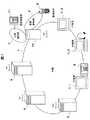
図1は、本発明の一実施形態が適用されたコミュニケーションシステムであるIM-VoIP(Voice over Internet Protocol)連携システムの概略図である。
【0016】
図示するように、IP網1には、IMクライアントのプレゼンス情報を管理するIMプレゼンス管理サーバ(以下、IMサーバと呼ぶ)4と、VoIPを利用した音声チャットのためのコネクションを管理するVoIP通信コネクション管理サーバ(以下、APサーバと呼ぶ)5と、音声データのミキシングを行なって多者音声通話を実現するためのメディアサーバ(以下、MDサーバと呼ぶ)6と、IMクライアントが搭載された複数のIP端末7-1〜7-3と、無線通信網2および公衆電話網(PSTN)3とIP網1との間の音声中継を行なう音声中継サーバ(以下、VRサーバと呼ぶ)10と、が接続されている。ここで、無線通信網2には、IMクライアントが搭載された携帯電話機等の無線端末9が接続され、公衆電話網3には、IMクライアントが搭載された固定電話機11が接続されている。
【0017】
以上のような構成において、IP端末7-1〜7-3は、単独で、あるいは、VoIP電話機8や無線端末9や固定電話機11と共に、IMサーバ4、APサーバ5およびMDサーバ6を利用して、マルチメディアによるチャットを行なうことができる。例えば、グループあるいは1対1において、テキストなどの電子文書によるチャット(以下、テキストチャットと呼ぶ)や音声によるチャット(以下、音声チャットと呼ぶ)を行なうことができる。
【0018】
次に、上記のIM-VoIP連携システムを構成する各装置について説明する。
【0019】
先ず、IMサーバ4について説明する。
【0020】
上述したように、IMサーバ4は、IMクライアントのプレゼンス情報を管理する。図2に、IMサーバ4の概略構成を示す。
【0021】
図示するように、IMサーバ4は、CPU41と、メモリ42と、HDD等の外部記憶装置43と、キーボード、マウス、ペン等の入力装置44と、スピーカ、ディスプレイ等の出力装置45と、IP網1で通信を行うためのIP網IF(インタフェース)46と、これらの各装置41〜46を接続するためのバス47と、を備えた一般的なコンピュータシステムにおいて、CPU41がメモリ42上にロードされた所定のプログラムを実行して、吹出し枠48内に示した機能ブロック481〜487を構成することにより、実現される。ここで、機能ブロック481〜487を構成するためのプログラムは、図示していない読取装置を介してCD-ROM等の記憶媒体(不図示)から、あるいは、IP網IF46を介してIP網1から、メモリ42に直接ロードされてもよい。あるいは、一旦、外部記憶装置43に記憶されてから、メモリ42にロードされてもよい。
【0022】
パケット分解部481は、IP網1から自装置宛のIPパケットを受信し、当該パケットのIPヘッダおよびTCP/UDPヘッダを処理して、ペイロードを抽出する。
【0023】
解析・データ/コマンド振分部482は、パケット分解部481で処理されたペイロードの中身を解析して、当該中身をデータおよびコマンドに振り分ける。
【0024】
データ処理部483は、解析・データ/コマンド振分部482で振り分けられたデータに対し、IMに必要な処理を施す。例えば、カンファレンス毎に、カンファレンスに参加している各IMクライアントから受信したテキストデータを、新しいものから所定容量分だけ保持し、保持しているテキストデータをマージして、テキストチャット用データを生成する。
【0025】
コマンド処理部484は、解析・データ/コマンド振分部482で振り分けられたコマンドの内容に従って、IMに必要な処理を行なう。例えば、IMクライアントからのカンファレンス設定要求コマンドに従い、新たなカンファレンスを設定したり、参加要求コマンドに従い、他のIMクライアントにカンファレンス参加を呼びかけたりするのに必要な処理を行なう。
【0026】
出力データ生成部485は、データ処理部483およびコマンド処理部484での処理結果に応じて出力データを生成する。
【0027】
パケット生成部486は、出力データ生成部485で生成された出力データに、TCP/UDPヘッダおよびIPヘッダを付加してIPパケットを生成し、IP網1へ送出する。
【0028】
コネクション管理部487は、IMクライアントのプレゼンス情報の管理を行なう。そして、プレゼンス状態に従い、上記の各機能ブロック481〜486を制御して、IMクライアントとのコネクション間を中継する。これにより、IMクライアント間のチャットを実現する。
【0029】
なお、パケット分解部481およびパケット生成部486は、例えば、IP網IF46内に集積ロジックICなどを用いてハードウェア的に構成してもよい。
【0030】
図3は、コネクション管理部487がプレゼンス情報を管理するために用いるプレゼンス情報管理テーブル488の一例を示している。プレゼンス情報管理テーブル488は、例えば、外部記憶装置43に格納される。
【0031】
図示するように、IMクライアントのユーザのアカウント名を登録するためのフィールド431と、IMクライアントのアドレスを登録するためのフィールド432と、IMクライアントのユーザのニックネームを登録するためのフィールド433と、このIM-VoIP連携システムを利用するための認証キーを登録するためのフィールド434と、IMクライアントのプレゼンス情報を登録するためのフィールド435と、IMクライアントがチャットに利用できるメディア(テキストチャットおよび音声チャット)を登録するためのフィールド436と、IMクライアントが参加するカンファレンスルームのアドレス(IPアドレスもしくはDNSおよびポート番号)を登録するためのフィールド437と、カンファレンスルームのニックネームを登録するためのフィールド438と、IMクライアントのユーザより予め通知された、このIMクライアントがチャットできる仲間のIMクライアントのアカウント名を登録するためのフィールド439と、を含んで1つのレコード440が構成されている。
【0032】
ここで、フィールド432には、IMクライアントのアドレスとして、IMクライアントが搭載された端末がIP端末の場合はそのIPアドレスもしくはDNSが登録され、IMクライアントが搭載された端末が携帯電話機や固定電話機の場合は、その電話番号と、携帯電話機や固定電話機およびIP網1間の音声中継を行なうVRサーバ10のIPアドレスもしくはDNSとが登録される。
【0033】
また、フィールド435には、プレゼンス情報として、オフラインを示す情報(off)、オンラインであるがアイドルであることを示す情報(idle)、テキストチャット中であることを示す情報(text)、音声チャット中であることを示す情報(voice)、そして、テキストチャット中および音声チャット中の両方であることを示す情報(text/voice)のいずれかが登録される。
【0034】
また、フィールド437には、カンファレンスルームのアドレスとして、カンファレンスルームに割り当てたIPアドレスが登録される。
【0035】
なお、ユーザが複数のIMクライアントを使用する場合、例えば、テキストチャットにはクライアント端末7-1を用い、音声チャットにはVoIP電話機8を用いる場合、それぞれについてレコード440が登録される。
【0036】
次に、APサーバ5について説明する。
【0037】
上述したように、APサーバ5は、VoIPを利用した音声チャットのためのコネクションを管理する。図4に、APサーバ5の概略構成を示す。
【0038】
図示するように、APサーバ5は、IMサーバ4と同様のハードウエア構成を持つコンピュータシステムにおいて、CPU41がメモリ42上にロードされた所定のプログラムを実行して、吹出し枠58内に示した機能ブロック581〜585を構成することにより、実現される。ここで、機能ブロック581〜585を構成するためのプログラムは、IMサーバ4の場合と同様に、図示していない読取装置を介してCD-ROM等の記憶媒体(不図示)から、あるいは、IP網IF46を介してIP網1から、メモリ42に直接ロードされてもよい。あるいは、一旦、外部記憶装置43に記憶されてからメモリ42にロードされてもよい。
【0039】
パケット分解部581は、IP網1から自装置宛のIPパケットを受信し、当該パケットのIPヘッダおよびTCP/UDPヘッダを処理して、ペイロードを抽出する。
【0040】
解析・処理部582は、パケット分解部581で処理されたペイロードの中身を解析して、そこに格納されたコマンドの内容に従い、音声チャットに必要な処理を行なう。例えば、IMクライアントからの音声チャット要求コマンドに従い、このIMクライアントが参加するカンファレンスの仲間に音声チャットへの参加を呼びかけたりするのに必要な処理を行なう。
【0041】
出力データ生成部583は、解析・処理部582での処理結果に応じて出力データを生成する。
【0042】
パケット生成部584は、出力データ生成部583で生成された出力データに、TCP/UDPヘッダおよびIPヘッダを付加してIPパケットを生成し、IP網1へ送出する。
【0043】
コネクション管理部585は、音声チャットのコネクション管理を行なう。つまり、上記の各機能ブロック581〜584を制御して、IMクライアントおよびMDサーバ6間のコネクションを管理する。これにより、MDサーバ6を介したIMクライアント間の音声チャットを実現する。
【0044】
なお、パケット分解部581およびパケット生成部584は、例えばIP網IF46内に集積ロジックICなどを用いてハードウェア的に構成してもよい。
【0045】
図5は、コネクション管理部585が音声チャットを管理するために用いるVoIPコネクション管理テーブル586の一例を示している。VoIPコネクション管理テーブル586は、例えば、外部記憶装置43に格納される。
【0046】
図示するように、IMクライアントのユーザのアカウント名を登録するためのフィールド531と、IMクライアントのアドレスを登録するためのフィールド532と、IMクライアントのユーザのニックネームを登録するためのフィールド533と、VoIPパケットで運ぶ音声信号の符号化方式の情報を登録するためのフィールド534と、IMクライアントが参加している音声チャットに用いているMDサーバ6のアドレス(IPアドレスもしくはDNSおよびポート番号、音声チャット用アドレスと呼ぶ)を登録するためのフィールド535と、カンファレンスルームのニックネームを登録するためのフィールド536と、を含んで1つのレコード540が構成されている。
【0047】
次に、IP端末7について説明する。
【0048】
上述したように、IP端末7には、チャットを楽しむためのIMクライアントが搭載されている。図6に、IP端末7の概略構成を示す。
【0049】
図示するように、IP端末7は、IMサーバ4と同様のハードウエア構成を持つコンピュータシステムにおいて、CPU41がメモリ42上にロードされた所定のプログラム(IMクライアントプログラム)を実行して、吹出し枠78内に示された機能ブロック781〜794を構成することにより、実現される。ここで、機能ブロック781〜794を構成するためのIMクライアントプログラムは、IMサーバ4の場合と同様に、図示していない読取装置を介してCD-ROM等の記憶媒体(不図示)から、あるいは、IP網IF46を介してIP網1から、メモリ42に直接ロードされてもよい。あるいは、一旦、外部記憶装置43に記憶されてから、メモリ42にロードされてもよい。
【0050】
パケット分解部781は、IP網1から自装置宛のIPパケットを受信し、当該パケットのIPヘッダおよびTCP/UDPヘッダを処理して、ペイロードを抽出する。
【0051】
解析・音声パケット/データ/コマンド振分部782は、パケット分解部781で処理されたペイロードの中身を解析して、当該中身を音声パケット(VoIPパケット)、データおよびコマンドに振り分ける。
【0052】
データ処理部783は、解析・音声パケット/データ/コマンド振分部782で振り分けられたデータの種別を解析し、その種別に応じた処理を行なって、その結果を出力データ生成部786に知らせる。
【0053】
コマンド処理部784は、解析・音声パケット/データ/コマンド振分部782で振り分けられたコマンドの内容を解析し、その内容に従って処理を行ない、その結果を出力データ生成部786に知らせる。
【0054】
出力データ生成部485は、データ処理部483およびコマンド処理部484での処理結果に応じて出力データを生成し、これを出力装置45のディスプレイやスピーカなどから出力する。
【0055】
音声パケット分解部785は、解析・音声パケット/データ/コマンド振分部782で振り分けられた音声パケットのヘッダを処理して、そのペイロードを抽出する。
【0056】
デコーダ787は、音声パケット分解部785より抽出されたペイロードに格納されている符号化された音声データを復号化する。
【0057】
D/A変換部788は、デコーダ787で復号化されたデジタルの音声データをアナログ音声信号に変換し、出力装置45のスピーカから出力する。
【0058】
A/D変換部790は、入力装置44のマイクから送られてきたアナログ音声信号をディジタルの音声データに変換する。
【0059】
エンコーダ791は、A/D変換部790より出力されたデジタルの音声データを符号化する。
【0060】
音声パケット生成部793は、エンコーダ791より出力された、符号化された音声データを音声パケット(VoIPパケット)化する。
【0061】
イベント解析部789は、入力装置44を介してユーザより入力された指示(イベント)を解析し、その解析結果をデータ/コマンド生成部792に送信する。
【0062】
データ/コマンド生成部792は、イベント解析部789での解析結果に従い、データあるいはコマンドを生成する。例えば、解析したイベントが音声チャットの開始要求に関する指示である場合は、音声チャット要求コマンドを生成する。また、解析したイベントがテキストチャットのメッセージの受け付けである場合は、このメッセージを表すデータを作成する。
【0063】
パケット生成部794は、音声パケット生成部793で生成された音声パケット、データ/コマンド生成部792で生成されたデータおよびコマンドのそれぞれをIPパケット化して、IP網1へ送出する。
【0064】
なお、パケット分解部781およびパケット生成部794は、例えば、IP網IF46内に、集積ロジックICなどを用いてハードウェア的に構成してもよい。また、D/A変換部788およびA/D変換部790は、それぞれ、出力装置45および入力装置44(あるいはこれらの装置とのインターフェース)内に、ハードウエアとして構成される。
【0065】
図7は、IMクライアントがIMに参加するために必要なプロファイルデータ686の一例を示している。プロファイルデータ686は、例えば、外部記憶装置43に格納される。
【0066】
図示するように、タグ631には、IMクライアントのユーザのニックネームが登録される。タグ632には、IMクライアントのユーザのアカウント名、認証キーおよびアドレスが登録される。タグ633には、IMサーバ4のアドレスが登録される。そして、タグ634には、APサーバ5のアドレスが登録される。なお、この例では、プロファイルデータをXML(eXtensible Markup Language)形式としているが、表形式でもテキストファイル形式でもかまわない。
【0067】
なお、VoIP電話機8、無線端末9および固定電話機11は、基本的に既存の装置を用いることができる。これらの装置も図7に示すプロファイルデータ686を保持しており、このプロファイルデータ686を使ってIMに参加する。
【0068】
なお、IP端末7でテキストチャットのみを行ない、音声チャットはVoIP電話機8や無線端末9や固定電話機11を用いて行なう場合、吹出し枠78内の音声チャットに関わる機能ブロック(機能ブロック785、787、788、790、791および793)は、IP端末7に不要である。
【0069】
次に、MDサーバ6について説明する。
【0070】
上述したように、MDサーバ6は、音声データのミキシングを行なって多者音声通話を行なう。図8に、MDサーバ6の概略構成を示す。
【0071】
図示するように、MDサーバ6は、IMサーバ4と同様のハードウエア構成を持つコンピュータシステムにおいて、CPU41がメモリ42上にロードされた所定のプログラムを実行して、吹出し枠88内に示した機能ブロック881〜888を構成することにより、実現される。ここで、機能ブロック881〜888を構成するためのプログラムは、IMサーバ4の場合と同様に、図示していない読取装置を介してCD-ROM等の記憶媒体(不図示)から、あるいは、IP網IF46を介してIP網1から、メモリ42に直接ロードされてもよい。あるいは、一旦、外部記憶装置43に記憶されてからメモリ42にロードされてもよい。
【0072】
パケット分解部881は、IP網1から自装置宛のIPパケットを受信し、当該パケットのIPヘッダおよびTCP/UDPヘッダを処理して、ペイロードを抽出する。
【0073】
解析・音声パケット/コマンド振分部882は、パケット分解部881で処理されたペイロードの中身を解析して、当該中身を音声パケット(VoIPパケット)およびコマンドに振り分ける。
【0074】
コマンド処理部883は、解析・音声パケット/コマンド振分部882で振り分けられたコマンドの内容を解析し、その内容に従って処理を行ない、その結果を出力データ生成部884に知らせる。
【0075】
出力データ生成部884は、コマンド処理部883での処理結果に応じて出力データを生成する。
【0076】
音声パケット分解部885は、解析・音声パケット/コマンド振分部882で振り分けられた音声パケットのヘッダを処理して、そのペイロードを抽出する。
【0077】
デコーダ886は、音声パケット分解部785より抽出されたペイロードに格納されている符号化された音声データを復号化する。
【0078】
ミキサ887は、あるIMクライアント(注目IMクライアントと呼ぶ)が参加している音声チャットに参加している他のIMクライアントの符号化された音声データを、デコーダ886から収集して、ミックス(合成)する。そして、この合成音声データを、注目IMクライアント向けの合成音声データとする。この処理を、デコーダ886で復号化された音声データの全ての送信元IMクライアント各々に対して行なう。
【0079】
エンコーダ888はミキサ887で生成された合成音声データを符号化する。
【0080】
音声パケット生成部889は、エンコーダ887より出力された、符号化された音声データを音声パケット(VoIPパケット)化する。
【0081】
パケット生成部889は、音声パケット生成部889で生成された音声パケットおよび出力データ生成部886で生成されたデータのそれぞれをIPパケット化して、IP網1へ送出する。
【0082】
なお、パケット分解部881およびパケット生成部889は、例えばIP網IF46内に集積ロジックICなどを用いてハードウェア的に構成してもよい。
【0083】
次に、VRサーバ10について説明する。
【0084】
上述したように、VRサーバ10は、無線通信網2および公衆電話網3とIP網1との間の音声中継を行なう。図9に、VRサーバ10の概略構成を示す。
【0085】
図示するように、VRサーバ10は、IMサーバ4と同様のハードウエア構成に、公衆電話網3や無線通信網2を介して通信を行なうための通信装置48が追加された構成を持つコンピュータシステムにおいて、CPU41がメモリ42上にロードされた所定のプログラムを実行して、吹出し枠98内に示した機能ブロック981〜987を構成することにより、実現される。ここで、機能ブロック981〜987を構成するためのプログラムは、IMサーバ4の場合と同様に、図示していない読取装置を介してCD-ROM等の記憶媒体(不図示)から、あるいは、IP網IF46を介してIP網1から、メモリ42に直接ロードされてもよい。あるいは、一旦、外部記憶装置43に記憶されてから、メモリ42にロードされてもよい。
【0086】
パケット分解部981は、IP網1から自装置宛のIPパケットを受信し、当該パケットのIPヘッダおよびTCP/UDPヘッダを処理して、ペイロードに格納されている音声パケット(VoIPパケット)を抽出する。
【0087】
音声パケット分解部982は、パケット分解部981で抽出された音声パケットのヘッダを処理して、そのペイロードを抽出する。
【0088】
デコーダ983は、音声パケット分解部982より抽出されたペイロードに格納されている符号化された音声データを復号化し、これを通信装置48を介して通信相手に送出する。
【0089】
エンコーダ984、通信装置48を介して通信相手より受け取った音声データを符号化する。
【0090】
音声パケット生成部985は、エンコーダ984より出力された、符号化された音声データを音声パケット(VoIPパケット)化する。
【0091】
パケット生成部986は、音声パケット生成部985で生成された音声パケットをIPパケット化して、IP網1へ送出する。
【0092】
呼制御処理部987は、上記の各機能ブロック981〜986を制御して、公衆電話網3や無線通信網2上の通信相手(固定電話機11や無線端末9)との間の呼の制御および管理を行なう。また、MDサーバ6とのコネクションを管理する。これにより、MDサーバ6と固定電話機11や無線端末9との間でやり取りされる音声データを中継する。
【0093】
なお、パケット生成部986は、例えばIP網IF46内に集積ロジックICなどを用いてハードウェア的に構成してもよい。
【0094】
次に、上記構成のIM-VoIP連携システムの動作について説明する。
【0095】
先ず、本実施形態のIM-VoIP連携システムの第1の動作例として、テキストチャットから音声チャットに移行する場合を説明する。
【0096】
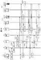
図10および図11は、本実施形態のIM-VoIP連携システムの第1の動作例であるテキストチャットから音声チャットに移行する場合の動作を説明するための図である。
【0097】
この例において、ニックネーム「taro」を持つユーザは、テキストチャット機能および音声チャット機能の両方(図6の吹出し枠78内の全ての機能ブロック781〜794)を備えたIP端末7-2(IMクライアントのアカウント名:client A)を用いてIMに参加し、ニックネーム「hanako」を持つユーザは、テキストチャット機能のみ(図6の吹出し枠78内の機能ブロック781〜784、786、789、792および794)を備えたIP端末7-1(IMクライアントのアカウント名:client D)およびVoIP電話機8(IMクライアントのアカウント名:client E)を用いてIMに参加し、そして、ニックネーム「yoshi」を持つユーザは、テキストチャット機能のみを備えたIP端末7-3(IMクライアントのアカウント名:client F)および無線端末9(IMクライアントのアカウント名:client G)を用いてIMに参加しているものとする。
【0098】
また、図10および図11において、IP端末7-1、7-3、VoIP電話機8および無線端末9は、IMサーバ4へのログイン処理が既に完了しているものとする。
【0099】
まず、IP端末7-2において、イベント解析部789は、ユーザ「taro」よりの指示に従い、データ/コマンド生成部792に、自装置に格納されているプロファイルデータ686を含むログイン要求コマンドを生成させる。このログイン要求コマンドは、パケット生成部794にてIPパケット化され、IP網1を介して、プロファイルデータ686に登録されているアドレスより特定されるIMサーバ4へ送信される(S1001)。
【0100】
IMサーバ4において、コマンド処理部484は、パケット分解部481および解析・データ/コマンド振分部482を介して、IP端末7-2よりログイン要求コマンドを受け取ると、このログイン要求コマンドに含まれているプロファイルデータ686に登録されているIMクライアントのアカウント名(client A)と同じアカウント名がフィールド431に登録されているレコード440を、プレゼンス情報管理テーブル488から特定する。そして、特定したレコード440のフィールド433および434に登録されているクライアントニックネームおよび認証キーと、プロファイルデータ686に登録されているクライアントニックネームおよび認証キーとが一致するか否かを確認することで、ログインを許可するか否かを決定する。ログインを許可するならば、出力データ生成部485に、ログイン許可メッセージを生成させる。このログイン許可メッセージは、パケット生成部486にてIPパケット化され、IP網1を介して、ログイン要求コマンドの送信元であるIP端末7-2へ送信される(S1002)。
【0101】
IP端末7-2において、コマンド処理部784は、パケット分解部781および解析・音声パケット/データ/コマンド振分部782を介して、IMサーバ4よりログイン許可メッセージを受け取ると、その旨をイベント解析部789に通知する。これを受けて、イベント解析部789は、ユーザ「taro」よりの指示に従い、データ/コマンド生成部792に、自身のIMクライアントのプレゼンス情報(例えば、チャット可能であることを示す情報(available)や、忙しくてチャットできないことを示す情報(Don't Disturb)など)を生成させる。このプレゼンス情報は、パケット生成部794にてIPパケット化され、IP網1を介して、プロファイルデータ686に登録されているアドレスより特定されるIMサーバ4へ送信される(S1003)。
【0102】
さて、IMサーバ4において、コマンド処理部484は、パケット分解部481および解析・データ/コマンド振分部482を介して、IP端末7-2よりプレゼンス情報を受け取ると、プレゼンス情報管理テーブル488から、IP端末7-2に搭載されているIMクライアントのアカウント名(client A)を持つレコード440を特定し、このレコード440のフィールド435に、受け取ったプレゼンス情報を登録する。
【0103】
次に、IP端末7-2において、イベント解析部789は、データ/コマンド生成部792に、チャット仲間のプレゼンス情報のダウンロード要求コマンドを生成させる。このダウンロード要求コマンドは、パケット生成部794にてIPパケット化され、IP網1を介して、プロファイルデータ686に登録されているアドレスより特定されるIMサーバ4へ送信される(S1004)。
【0104】
IMサーバ4において、コマンド処理部484は、パケット分解部481および解析・データ/コマンド振分部482を介して、IP端末7-2よりダウンロード要求コマンドを受け取ると、プレゼンス情報管理テーブル488から、IP端末7-2に搭載されているIMクライアントのアカウント名(client A)を持つレコード440を特定する。また、このレコード440のフィールド439に登録されているバディリストを入手する。そして、入手したバディリストに登録されているアカウント名を持つ各レコード440(チャット仲間のIMクライアントのレコード)を、プレゼンス情報管理テーブル488から特定する。それから、データ/コマンド生成部792に、特定した各レコード440のフィールド431〜433、435〜438の情報を含むバディリスト通知を生成させる。このバディリスト通知は、パケット生成部794にてIPパケット化され、IP網1を介して、ダウンロード要求コマンドの送信元であるIP端末7-2へ送信される(S1005)。
【0105】
さて、IP端末7-2において、コマンド処理部784は、パケット分解部781および解析・音声パケット/データ/コマンド振分部782を介して、IMサーバ4よりバディリスト通知を受け取ると、このバディリスト通知に含まれている情報に基づいて、出力データ生成部786に、チャット仲間のプレゼンス情報や利用可能メディアや参加中のカンファレンスルームを示すデータを生成させ、このデータを表示装置に表示するなどしてユーザ「taro」に知らせる。ユーザ「taro」は、このデータを基にチャット相手を決定できる。
【0106】
上述したように、ユーザ「taro」は、バディリスト通知に含まれている情報に基づいてチャット仲間のプレゼンス情報や利用可能メディアや参加中のカンファレンスルームを知ることができる。ここで、ユーザ「taro」が、例えば開設中のカンファレンスルームでは取り扱っていない話題をチャットするために、新たなカンファレンスルームの開設指示を、入力装置44に入力したとする。すると、IP端末7-2において、イベント解析部789は、これを検知し、データ/コマンド生成部792に、カンファレンスルームの設定要求コマンドを生成させる。この設定要求コマンドは、パケット生成部794にてIPパケット化され、IP網1を介して、プロファイルデータ686に登録されているアドレスより特定されるIMサーバ4へ送信される(S1006)。
【0107】
IMサーバ4において、コマンド処理部484は、パケット分解部481および解析・データ/コマンド振分部482を介して、IP端末7-2よりカンファレンスルームの設定要求コマンドを受け取ると、新たに開設するカンファレンスルームに、自身が保有しているアドレスの中から任意のアドレスを割り当てる。それから、データ/コマンド生成部485に、新たに開設するカンファレンスルームのニックネームや入出制限事項などのカンファレンスルーム開設に必要な各種条件の設定要求コマンドを生成させる。この設定要求コマンドは、パケット生成部486にてIPパケット化され、IP網1を介して、カンファレンスルームの設定要求コマンドの送信元であるIP端末7-2へ送信される(S1007)。
【0108】
IP端末7-2において、コマンド処理部784は、パケット分解部781および解析・音声パケット/データ/コマンド振分部782を介して、IMサーバ4よりカンファレンスルーム開設に必要な各種条件の設定要求を受け取ると、出力データ生成部786に、前記各種条件を受け付けるための入力画面データを表示装置に表示するなどして、ユーザ「taro」に前記各種条件を入力させる。さて、イベント解析部789は、ユーザ「taro」よりカンファレンスルーム開設に必要な各種条件の入力を受け付けると、データ/コマンド生成部792に、ユーザ「taro」より受け付けた各種条件を含む設定データを生成させる。この設定データは、パケット生成部794にてIPパケット化され、IP網1を介して、プロファイルデータ686に登録されているアドレスより特定されるIMサーバ4へ送信される(S1008)。
【0109】
さて、IMサーバ4において、コマンド処理部484は、パケット分解部481および解析・データ/コマンド振分部482を介して、IP端末7-2よりカンファレンスルーム開設に必要な各種条件の設定データを受け取ると、この設定データと、S1007にてこのカンファレンスルームのために割り当てたアドレスとを用いて、このカンファレンスルームを開設する。そして、前記設定データの送信元であるIP端末7-2のIMクライアントのアカウント名(client A)を持つレコード440を、プレゼンス情報管理テーブル488から特定し、このレコード440のフィールド437、438に、このカンファレンスルームのアドレスおよびニックネームを登録する(S1009)。これと共に、このレコード440のフィールド435に、テキストチャット中であることを示すプレゼンス情報を登録する。また、コマンド処理部484は、出力データ生成部485に、このカンファレンスルームのアドレスおよびニックネームを含んだ開設完了メッセージを作成させる。この開設完了メッセージはパケット生成部486にてIPパケット化され、IP網1を介して、前記設定データの送信元であるIP端末7-2へ送信される。
【0110】
IP端末7-2において、コマンド処理部784は、パケット分解部781および解析・音声パケット/データ/コマンド振分部782を介して、IMサーバ4よりカンファレンスルームの開設完了メッセージを受け取ると、出力データ生成部786に、前記開設完了メッセージに含まれているカンファレンスルームのアドレスやニックネームの表示データを生成させ、これを表示装置に表示するなどして、ユーザ「taro」に、開設したカンファレンスルームの内容を知らせる。これにより、ユーザ「taro」は、IP端末7-2の表示装置などに表示されているチャット仲間のプレゼンス情報などを見て、自身が開設したカンファレンスルームに誘うチャット仲間を決定することができる。
【0111】
さて、IP端末7-2において、イベント解析部789は、ユーザ「taro」よりカンファレンスルームに誘うチャット仲間のアカウント名の指定を受け付けると、データ/コマンド生成部792に、この指定およびカンファレンスルームのアドレスあるいはニックネームを含むカンファレンス参加要求コマンドを作成させる。この参加要求コマンドは、パケット生成部794にてIPパケット化され、IP網1を介して、プロファイルデータ686に登録されているアドレスより特定されるIMサーバ4へ送信される(S1010)。
【0112】
IMサーバ4において、コマンド処理部484は、パケット分解部481および解析・データ/コマンド振分部482を介して、IP端末7-2よりカンファレンス参加要求コマンドを受け取ると、この参加要求コマンドに含まれているアカウント名を持つ各レコード440を、プレゼンス情報管理テーブル488から特定する。そして、特定した各レコード440のフィールド435、436に登録されているプレゼンス情報、利用メディアを参照して、このレコード440のIMクライアントがテキストチャットに参加できるか否かを確認する。それから、参加可能と判断したIMクライアントのレコード440のフィールド432に登録されているアドレスを取得する。
【0113】
次に、コマンド処理部484は、出力データ生成部485に、カンファレンスルームのアドレス、ニックネームおよび参加の呼びかけ主であるIMクライアントのニックネーム「taro」とを含んだ参加呼びかけコマンドを、参加可能と判断したIMクライアント毎に作成させる。この参加可能と判断したIMクライアント毎に作成された参加呼びかけコマンドは、パケット生成部486にて、IPパケット化され、IP網1を介して、送信先のIMクライアント各々のアドレスへ送信される(S1011)。ここでは、IP端末7-1(IMクライアントのアカウント名:client D)、および、IP端末7-3(IMクライアントのアカウント名:client F)へ、参加呼びかけコマンドを送信している。
【0114】
さて、IP端末7-1において、コマンド処理部784は、パケット分解部781および解析・音声パケット/データ/コマンド振分部782を介して、IMサーバ4より参加呼びかけコマンドを受け取ると、出力データ生成部786に、参加呼びかけコマンドに含まれているカンファレンスルームのアドレスやニックネームおよび参加呼びかけ主であるIMクライアントのニックネーム「taro」の表示データを生成させ、これを表示装置に表示するなどして、IP端末7-1のユーザ「hanako」に、ユーザ「taro」から参加呼びかけがあったことを知らせる。これにより、ユーザ「hanako」は、ユーザ「taro」の参加呼びかけに応答するか否かを決定することができる。IP端末7-3でも同様の処理が行なわれ、これにより、ユーザ「yoshi」は、ユーザ「taro」の参加呼びかけに応答するか否かを決定することができる。
【0115】
IP端末7-1において、イベント解析部789は、ユーザ「hanako」より参加呼びかけに応答する旨の指示を受け付けると、データ/コマンド生成部792に、カンファレンスルームのアドレスおよび/またはニックネームを含む入会要求コマンドを生成させる。この入会要求コマンドは、パケット生成部794にてIPパケット化され、IP網1を介して、参加呼びかけコマンドの送信元であるIMサーバ4へ送信される(S1012A)。IP端末7-3でも同様の処理が行なわれ、これにより、IP端末7-3からIMサーバ4へ、入会要求コマンドが送信される(S1012B)。
【0116】
IMサーバ4において、コマンド処理部484は、パケット分解部481および解析・データ/コマンド振分部482を介して、IP端末7-1より入会要求コマンドを受け取ると、このIP端末7-1に搭載されているIMクライアントのアカウント名(client D)を持つレコード440をプレゼンス情報管理テーブル488から特定する。そして、このレコード440のフィールド437、438に、この入会要求コマンドに含まれているカンファレンスルームのアドレスおよびニックネームを登録すると共に、このレコード440のフィールド435に、テキストチャット中であることを示すプレゼンス情報を登録する。さらに、コマンド処理部484は、コネクション管理部487に、カンファレンスルームのアドレスを指定してコネクション管理を要求する。
【0117】
これを受けて、コネクション管理部487は、図2の吹出し枠48内の機能ブロック481〜486を統括的に制御して、コマンド処理部484より指定されたカンファレンスルームのアドレスつまりIMサーバ4と、このカンファレンスルームアドレスが登録されているプレゼンス情報管理テーブル488の各レコード440に対応する各IP端末7との間のコネクションを管理する。
【0118】
また、コネクション管理部487は、データ処理部483に、前記各レコード440に登録されているIMクライアントのアカウント名およびアドレスを通知して、前記各レコード440に対応するIP端末7間のテキストチャットを行なわせる(S1013)。
【0119】
具体的には、データ処理部483は、テキストチャットに参加する各IP端末7から受信したテキストデータを、新しいものから所定容量分だけ保持すると共に、保持しているテキストデータをマージして、テキストチャット用データを生成する。このテキストチャット用データは、パケット生成部486でIPパケット化されて、テキストチャットに参加する各IP端末7へ送信される。
【0120】
このとき、各IP端末7では、次の処理が行なわれる。すなわち、イベント解析部789は、ユーザよりメッセージが入力されると、データ/コマンド生成部792に、このメッセージに応じたテキストデータを生成させる。このテキストデータは、パケット生成部794でIPパケット化されて、IMサーバ4へ送信される。一方、データ処理部783は、パケット分解部781および解析・音声パケット/データ/コマンド振分部782を介して、IMサーバ4よりテキストチャット用データを受け取ると、これを処理して表示装置に表示させる。
【0121】
IP端末7-2において、イベント解析部789は、テキストチャット中に、ユーザ「taro」より、チャット仲間の情報の要求指示を受け取ると、データ/コマンド生成部792に、自身のIMクライアントのアカウント名を含む仲間リスト要求コマンドを生成させる。この要求コマンドは、パケット生成部794にてIPパケット化され、IP網1を介してIMサーバ4へ送信される(S1014)。
【0122】
IMサーバ4において、コマンド処理部484は、パケット分解部481および解析・データ/コマンド振分部482を介して、IP端末7-2より仲間リスト要求コマンドを受け取ると、この要求コマンドに含まれているアカウント名がフィールド431に登録されているレコード440を、プレゼンス情報管理テーブル488から特定する。さらに、このレコード440のフィールド439に登録されているバディリストに記述されているアカウント名がフィールド431に登録されている各レコード440を、プレゼンス情報管理テーブル488から特定する。
【0123】
それから、コマンド処理部484は、出力データ生成部485に、特定した各レコード440に登録されている諸情報(但し、少なくとも認証キーは除く)を含む、チャット仲間各々の情報が登録された仲間リストを作成させる。この仲間リストは、パケット生成部486にて、IPパケット化され、IP網1を介して、仲間リスト要求の送信元であるIP端末7-2へ送信される(S1015)。
【0124】
IP端末7-2において、コマンド処理部784は、パケット分解部781および解析・音声パケット/データ/コマンド振分部782を介して、IMサーバ4より仲間リストを受け取ると、出力データ生成部786に、前記仲間リストに記述されている情報の表示データを生成させ、これを表示装置に表示するなどして、ユーザ「taro」に、チャット仲間の情報を知らせる。これにより、ユーザ「taro」は、実行中のテキストチャットを通じて、カンファレンスルームに参加している仲間が音声チャット可能か否かや、音声チャット可能な場合は、音声チャットにどのIMクライアント(アカウント名およびクライアントニックネームで特定できる)を使っているかなどを確認することができる。
【0125】
さて、ユーザ「taro」は、表示装置に表示された仲間リストの情報と、テキストチャットを通じてのやり取りとにより、カンファレンスに参加しているユーザ「hanako」、「yoshi」が、それぞれ「client E」、「client G」のアカウント名を持つIMクライアント(VoIP電話機8、無線端末9)を用いて音声チャットに参加できること、および、音声チャットに参加する意思があることを確認したとする。そして、アカウント名が「client E」、「client G」のIMクライアントとの音声チャット要求指示を入力装置44に入力したとする。
【0126】
IP端末7-2において、イベント解析部789は、ユーザ「taro」よりの音声チャット要求指示に従い、データ/コマンド生成部792に、自身のIMクライアントおよび音声チャットを呼びかけるIMクライアントの諸情報(アカウント名、クライアントアドレス、クライアントニックネームなど)と、参加中のカンファレンスルームのアドレスおよびニックネームとを含んだ音声チャット要求コマンドを生成させる。この音声チャット要求コマンドは、パケット生成部794にてIPパケット化され、IP網1を介して、プロファイルデータ686に登録されているアドレスより特定されるAPサーバ5へ送信される(S1016)。
【0127】
APサーバ5において、解析処理部582は、パケット分解部581を介して、音声チャット要求コマンドを受け取ると、出力データ生成部583に、音声チャット要求コマンドに含まれている各IMクライアントのアドレス(但し、IMクライアントが無線端末9や固定電話機11の場合は、VRサーバ10のアドレス)と、この音声チャットのためにMDサーバ6に割り当てるアドレス(音声チャット用アドレス)と、音声信号の符号化方式(音声チャットに参加する各IMクライアント(IMクライアントが無線端末9や固定電話機11の場合は、VRサーバ10)が共通して採用できる符号化方式。この情報はプレゼンス情報管理テーブル488の各レコード440に予め登録しておけばよい)と、を含んだミキシング設定要求コマンドを生成させる。このミキシング設定要求コマンドは、パケット生成部584にてIPパケット化され、IP網1を介して、MDサーバ6に送信される(S1017)。
【0128】
MDサーバ6において、コマンド処理部883は、パケット分解部881および解析・音声パケット/コマンド振分部882を介して、ミキシング設定要求コマンドを受け取ると、この設定要求コマンドに含まれている情報に従って、IMクライアント間で音声チャットが行なえるように、音声パケット分解部885、デコーダ886、ミキサ887および音声パケット生成部889の設定を行なう。
【0129】
一方、APサーバ5において、解析処理部582は、出力データ生成部583に、IP端末7-2より受け取った音声チャット要求コマンドに含まれているアドレスより特定される各IMクライアントに対する音声チャット呼出しコマンドを生成させる。この音声チャット呼び出しコマンドには、音声チャット用アドレスを含める。この音声チャット呼出しコマンドは、パケット生成部584でIPパケット化され、IP網1を介して、音声チャット要求コマンドに含まれているアドレスより特定される各IMクライアントへ送信される(S1018)。
【0130】
ここで、送信先のIMクライアントが無線端末9および固定電話機11に搭載されている場合、音声チャット呼出しコマンドに、音声チャット用アドレスに加え、このIMクライアントに対するプレゼンス情報管理テーブル488のレコード440のフィールド432に登録されている電話番号等をさらに含める。そして、音声チャット呼出しコマンドは、このフィールド432に登録されているIPアドレスより特定されるVRサーバ10へ送信される。VRサーバ10において、呼制御処理部987は、APサーバ5より音声チャット呼出しコマンドを受け取ると、この呼出しコマンドに含まれている電話番号等より特定される無線端末9に電話をかけて呼び出す(S1019)。
【0131】
以上により、音声チャット要求にて指定されている各IMクライアントがAPサーバ5により呼出される。IP端末7-2では、パケット分解部781、解析・音声パケット/データ/コマンド振分部782を介して、この呼出しコマンドがコマンド処理部784に到達する。コマンド処理部784は、出力データ生成部786に呼出し音データを生成させてスピーカから出力させるなどして、ユーザ「taro」に呼出しがあったことを知らせる。そして、イベント解析部789は、ユーザ「taro」よりの指示に従い、データ/コマンド生成部792に、この呼出しコマンドに対する応答メッセージを生成させる。この応答メッセージは、パケット生成部794でIPパケット化され、APサーバ5に送信される(S1020A)。同様に、VoIP電話機8、無線端末9でも、呼出しに対する応答メッセージが作成され、APサーバ5に送信される(S1020B、S1020C)。ここで、無線端末9からの応答メッセージは、VRサーバ10の呼制御処理部987により、APサーバ5に中継される(S1021)。
【0132】
APサーバ5において、解析・処理部582は、パケット分解部581を介して応答メッセージを受け取ると、この応答メッセージを送信したIMクライアントの情報(音声チャット要求コマンドに含まれていた情報)と、テキストチャットが行なわれているカンファレンスルームのニックネームと、MDサーバ6に割り当てた音声チャット用アドレスとを、コネクション管理部585に通知する。これを受けて、コネクション管理部585は、コネクション管理テーブル586に新たなレコード540を追加して、これらの情報をこのレコード540に登録する。そして、解析・処理部582は、呼出しコマンドを送信した全てのIMクライアントから応答メッセージを受け取ったならば、出力データ生成部583に、これらのIMクライアントの情報とMDサーバ6に割り当てられた音声チャット用アドレスとを含んだ設定完了コマンドを生成させる。この設定完了コマンドは、パケット生成部584でIPパケット化され、IP網1を介してIMサーバ4へ通知される(S1022)。
【0133】
IMサーバ4において、コマンド処理部484は、パケット分解部481および解析・データ/コマンド振分部482を介して設定完了コマンドを受け取ると、この設定完了コマンドに含まれている各IMクライアントの情報および音声チャット用アドレスを、コネクション管理部487に通知する。コネクション管理部487は、コマンド処理部484より受け取った各IMクライアントに対応するレコード440を、プレゼンス情報管理テーブル488から特定する。そして、特定した各レコード440のフィールド435に、音声チャット中であることを示すプレゼンス情報を登録すると共に、フィールド437に音声チャット用アドレスを登録する。さらに、フィールド437に、テキストチャットが行なわれているカンファレンスルームのニックネームを登録する。
【0134】
以上の処理が終了すると、MDサーバ6と各IMクライアント(IP端末7-2、VoIP電話機8および無線端末9)との間に、音声チャット用のコネクションが確立される。そして、MDサーバ6において、ミキシング処理が行なわれ、音声チャットに参加する各IMクライアントの音声データが合成されて、各IMクライアントに配信される(S1023)。
【0135】
具体的には、各IMクライアントから音声チャット用アドレスへ向けて送信された音声パケットは、パケット分解部881および解析・音声パケット/コマンド振分部882を介して、音声パケット分解部885に入力され、ヘッダ処理される。これにより、符号化された音声データが得られる。次に、デコーダ886にて符号化された音声データが復号化されて、ミキサ887に入力される。ミキサ887は、同じ音声チャット用アドレス向けに送信された音声パケットに関し、IMクライアント毎に音声データを所定時間分バッファリングすると共に、注目IMクライアント以外の各IMクライアントに対してバッファリングされた音声データを合成し、これを注目IMクライアント向けの合成音声データとする処理を、音声チャットに参加する全てのIMクライアントに対して行なう。以上のようにして作成された合成音声データは、エンコーダ888にて復号化された後に、音声パケット生成部880にて音声パケット(VoIPパケット)化される。それから、パケット生成部890でIPパケット化されて、合成音声データに対する注目IMクライアントへ送信される。
【0136】
このとき、IP端末7-2では、次の処理が行なわれる。すなわち、ユーザより入力された音声を表すアナログ音声信号は、A/D変換部790でデジタル音声信号に変換され、エンコーダ791にて符号化される。それから、符号化された音声データは、音声パケット生成部793にて音声パケット化され、さらに、パケット生成部794でIPパケット化されて、MDサーバ6の音声チャット用アドレスへ送信される。一方、音声パケット分解部785は、パケット分解部781および解析・音声パケット/データ/コマンド振分部782を介して、MDサーバ6より受け取った音声パケットがヘッダ処理される。これにより、符号化された音声データが得られる。次に、デコーダ787にて符号化された音声データが復号化され、D/A変換部788でアナログ音声信号に変換されて、スピーカから出力される。
【0137】
VoIP電話機8でも、IP端末7-2と同様の処理が行なわれる。一方、無線端末9では、VRサーバ10にて、音声パケットを格納したIPパケットと、無線通信網2が採用する信号形式の音声信号との間の変換処理が行なわれる(S1024)。このため、無線端末9は、携帯電話機等の既存の無線端末を用いることができる。
【0138】
さて、IP端末7-2において、イベント解析部789は、ユーザ「taro」より音声チャットの終了指示を受け取ると、データ/コマンド生成部792に、自身のIMクライアントの情報(アカウント名やアドレス)を含んだ音声切断要求コマンドを生成させる。この音声切断要求コマンドは、パケット生成部794にてIPパケット化され、プロファイルデータ686に登録されているアドレスより特定されるAPサーバ5へ送信される(S1025)。
【0139】
APサーバ5において、解析・処理部582は、パケット分解部581を介して音声切断要求コマンドを受け取ると、パケット生成部584を介して、このコマンドをIMサーバ4およびMDサーバ6に転送する(S1026)。
【0140】
IMサーバ4において、コマンド処理部484は、パケット分解部481および解析・データ/コマンド振分部482を介して音声切断要求コマンドを受け取ると、その旨をコネクション管理部487に通知する。コネクション管理部487は、音声切断要求コマンドに含まれているIMクライアントの情報(アカウント名やクライアントアドレス)を持つレコード440を、プレゼンス情報管理テーブル488から特定する。そして、特定したレコード440に登録されている音声チャットに関する情報(フィールド435に登録されている音声チャット中であることを示すプレゼンス情報や、フィールド437に登録されている音声チャット用アドレス)を削除する。その結果、対応するIMクライアントがチャット中の状態でなくなったならば、フィールド435にアイドル状態であることを示す情報を登録すると共に、フィールド438に登録されているカンファレンスニックネームを削除する。
【0141】
また、MDサーバ6において、コマンド処理部883は、パケット分解部881および解析・音声パケット/コマンド振分部882を介して音声切断要求コマンドを受け取ると、ミキサ887を制御し、この音声切断要求コマンドに含まれているIMクライアントに対する音声データのバッファリングおよびこのIMクライアント向けの合成音声データの作成処理を中止する。その結果、VoIP電話機8および無線端末9間でのみ音声チャットが行なわれることになる(S1027)。なお、VoIP電話機8および無線端末9が音声チャットを終了する場合も、IP端末7-2の場合と同様の処理が行なわれる。そして、全てのIMクライアントが音声チャットを終了することで、コネクション管理テーブル586からこの音声チャットのために割り当てていたアドレスが削除され、このアドレスが解放される。
【0142】
図12に、IP端末7に表示されるIMクライアントのユーザインタフェース例を示す。
【0143】
符号130は、IMクライアントのメインメニューバーを示している。メインメニューバー130には、プレゼンス情報に関する操作を示すアイコン131、1対1(Peer-to-Peer)による音声チャットを示すアイコン132、多者間通話による音声チャットを示すアイコン133、および、テキストチャットを示すアイコン134を含んでいる。
【0144】
ユーザが入力装置44を使ってアイコン131を選択すると、自身のIMクライアントのプレゼンス情報を設定するのか、それとも、仲間のIMクライアントのプレゼンス情報を取得/表示させるのかを、ユーザに選択させる。そして、仲間のIMクライアントのプレゼンス情報の取得/表示が選択された場合、チャット中でないならば、図10のS1004、S1005が行なわれて、バディリストに登録された仲間のプレゼンス情報などが表示エリア135内に表示される。一方、チャット中ならば、図11のS1014、S1015が行なわれて、チャット中の仲間のプレゼンス情報などが表示エリア135内に表示される。
【0145】
符号138は、仲間のIMクライアントから転送されたファイルの内容を表示する表示エリアである。
【0146】
符号140は、テキストチャットのための表示エリアであり、カンファレンスルームのニックネームを表示するエリア139と、テキストチャットの内容が表示されるエリア136と、ユーザから受け付けたテキストメッセージが表示されるエリア137とを含んでいる。この表示エリア140は、ユーザが入力装置44を使ってアイコン134を選択した場合に表示される。
【0147】
次に、上述の第1の動作例の変形例について説明する。
【0148】
図13は、上述の第1の動作例の変形例を説明するための図であり、図11に相当する部分の動作を説明するための図である。なお、図10に相当する部分の動作は、第1の動作例と同じである。
【0149】
上述の第1実施形態では、図11に示すように、IMサーバ4は、IP端末7-2より仲間リスト要求コマンドを受け取ると(S1014)、テキストチャット中の仲間のプレゼンス情報などを含んだ仲間リストを作成して、これをIP端末7-2に通知する(S1015)。そして、IP端末7-2にて、音声チャットを行なうIMクライアントの情報を含んだ音声チャット要求コマンドを作成し、これをAPサーバ5に送信している(S1016)。
【0150】
これに対し、この変形例では、図13に示すように、IMサーバ4は、IP端末7-2より仲間リスト要求コマンドを受け取ると(S1014)、テキストチャット中の仲間のプレゼンス情報およびプレゼンス管理情報テーブル488を用いて、IP端末7-2のユーザの代わりに、音声チャット可能な仲間のIMクライアントを特定し、IMクライアントの情報を含んだ音声チャット要求コマンドをAPサーバ5に送信する(S1015b)。それ以外は、図11と同様である。
【0151】
ここで、音声チャット可能な仲間のIMクライアントの特定は、次のようにして行なえばよい。まず、テキストチャット中の仲間のIMクライアント各々について、プレゼンス管理情報テーブル488の対応するレコード440のフィールド436に登録されている利用メディアに音声チャットが含まれているか否かを確認する。利用メディアに音声チャットが含まれているならば、このIMクライアントを音声チャット可能な仲間のIMクライアントに設定する。一方、利用メディアに音声チャットが含まれていないならば、このレコード440のフィールド439に登録されているバディリストに記述されているアカウント名を持つレコード440の中から、このIMクライアントと同じニックネームを持つレコード440があるか否か調べる。あるならば、このレコード440のフィールド435にアイドル中を示すプレゼンス情報が登録されており、且つ、フィールド436に登録されている利用メディアに音声チャットが含まれているか否かをさらに確認する。そして、これらの条件を満たすレコード440に対応するIMクライアントを、音声チャット可能な仲間のIMクライアントに設定する。
【0152】
次に、上述の第1の動作例の他の変形例について説明する。
【0153】
図14は、上述の第1の動作例の他の変形例を説明するための図であり、図11に相当する部分の動作を説明するための図である。なお、図10に相当する部分の動作は、第1の動作例と同じである。
【0154】
上述の第1実施形態では、図11に示すように、IP端末7-2は、IMサーバ4に仲間リスト要求コマンドを送信して(S1014)、テキストチャット中の仲間のプレゼンス情報などを含んだ仲間リストを、IMサーバ4より受け取る(S1015)。そして、IP端末7-2は、音声チャットを行なうIMクライアントの情報を含んだ音声チャット要求コマンドを作成し、これをAPサーバ5に送信している(S1016)。
【0155】
これに対し、この変形例では、図14に示すように、IP端末7-2は、自身のIMクライアントの情報およびカンファレンスルームの情報を含んだ音声チャット要求コマンドを、いきなりAPサーバ5に送信する(S1014b)。そして、APサーバ5が、IP端末7-2のIMクライアントの情報およびカンファレンスルームの情報を含んだ仲間リスト要求コマンドを作成して、IMサーバ4に送信する(S1015c)。IMサーバ4は、APサーバ5より仲間リスト要求コマンドを受け取ると、テキストチャット中の仲間のプレゼンス情報およびプレゼンス管理情報テーブル488を用いて、IP端末7-2のIMクライアントの仲間であって音声チャット可能な仲間のIMクライアントを特定し、この情報を仲間リストとして、APサーバ5に送信する(S1016b)。それ以外は、図11と同様である。
【0156】
次に、本実施形態のIM-VoIP連携システムの第2の動作例として、音声チャット中にテキストチャットを併用する場合を説明する。
【0157】
図15および図16は、本実施形態のIM-VoIP連携システムの第2の動作例である音声チャット中にテキストチャットを併用する場合の動作を説明するための図である。
【0158】
ここでも、図10および図11に示す第1の動作例と同様に、ニックネーム「taro」を持つユーザは、テキストチャット機能および音声チャット機能の両方を備えたIP端末7-2(IMクライアントのアカウント名:client A)を用いてIMに参加し、ニックネーム「hanako」を持つユーザは、テキストチャット機能のみを備えたIP端末7-1(IMクライアントのアカウント名:client D)およびVoIP電話機8(IMクライアントのアカウント名:client E)を用いてIMに参加し、そして、ニックネーム「yoshi」を持つユーザは、テキストチャット機能のみを備えたIP端末7-3(IMクライアントのアカウント名:client F)および無線端末9(IMクライアントのアカウント名:client G)を用いてIMに参加しているものとする。また、IP端末7-1、7-3、VoIP電話機8および無線端末9は、IMサーバ4へのログイン処理が既に完了しているものとする。
【0159】
まず、図10のS1001〜S1005と同様の処理が行なわれ、IP端末7-2に搭載されたIMクライアントのログイン、このIMクライアントのプレゼンス情報のIMサーバ4へのアップロード、および、仲間のIMクライアントのプレゼンス情報のIMサーバ4からIP端末7-2へのダウンロードが行なわれる(S2001〜S2005)。
【0160】
さて、ユーザ「taro」は、IP端末7-2に表示された仲間のIMクライアントのプレゼンス情報を参照して、音声チャットを行なうIMクライアントを決定し、IMクライアントの指定(client E、client G)を伴う音声チャット要求指示を入力したとする。IP端末7-2において、イベント解析部789は、これを検知して、データ/コマンド生成部792に、自身のIMクライアントおよび音声チャットを呼びかけるIMクライアントの諸情報(アカウント名、クライアントアドレス、クライアントニックネームなど)を含んだ音声チャット要求コマンドを生成させる。この音声チャット要求コマンドは、パケット生成部794にてIPパケット化され、IP網1を介して、プロファイルデータ686に登録されているアドレスより特定されるAPサーバ5へ送信される(S2006)。
【0161】
その後、図11のS1017〜S1024と同様の処理が行なわれ、IP端末7-2に搭載されたIMクライアント「client A」、VoIP電話機8に搭載されたIMクライアント「client E」および無線端末9に搭載されたIMクライアント「client G」間の音声チャットが開始される(S2007〜S2014)。
【0162】
さて、IP端末7-2において、イベント解析部789は、音声チャット中にユーザ「taro」よりチャット仲間の情報の要求指示を受け取ると、データ/コマンド生成部792に、自身のIMクライアントのアカウント名を含む仲間リスト要求コマンドを生成させる。この要求コマンドは、パケット生成部794にてIPパケット化され、IP網1を介して、プロファイルデータ686に登録されているアドレスより特定されるIMサーバ4へ送信される(S2015)。
【0163】
IMサーバ4において、コマンド処理部484は、パケット分解部481および解析・データ/コマンド振分部482を介して、IP端末7-2より仲間リスト要求コマンドを受け取ると、この要求コマンドに含まれているアカウント名がフィールド431に登録されているレコード440を、プレゼンス情報管理テーブル488から特定する。さらに、このレコード440のフィールド439に登録されているバディリストに記述されているアカウント名がフィールド431に登録されている各レコード440を、プレゼンス情報管理テーブル488から特定する。
【0164】
それから、コマンド処理部484は、出力データ生成部485に、特定した各レコード440に登録されている諸情報(但し、少なくとも認証キーは除く)を含む、チャット仲間各々の情報が登録された仲間リストを作成させる。この仲間リストは、パケット生成部486にて、IPパケット化され、IP網1を介して、仲間リスト要求の送信元であるIP端末7-2へ送信される(S2016)。
【0165】
IP端末7-2において、コマンド処理部784は、パケット分解部781および解析・音声パケット/データ/コマンド振分部782を介して、IMサーバ4より仲間リストを受け取ると、出力データ生成部786に、前記仲間リストに記述されている情報の表示データを生成させ、これを表示装置に表示するなどして、ユーザ「taro」に仲間の情報を知らせる。
【0166】
これにより、ユーザ「taro」は、表示装置に表示された仲間の情報と、実行中の音声チャットとを通じて、音声チャット中の仲間がテキストチャット可能であるか否かや、テキストチャット可能な場合は、テキストチャットにどのIMクライアント(アカウント名およびクライアントニックネームで特定できる)を使っているかなどを確認することができる。そして、音声チャットの補助として、テキストチャットのためのカンファレンスルームを設定できるか否かを確認することができる。
【0167】
さて、ユーザ「taro」は、表示装置に表示された仲間の情報および音声チャットによるやり取りを通じて、音声チャットに参加しているユーザ「hanako」、「yoshi」が、それぞれ「client D」、「client F」のアカウント名を持つIMクライアント(IP端末7-1、IP端末7-3)を用いてテキストチャットに参加できること、および、テキストチャットに参加する意思があることを確認したとする。そして、このテキストチャットのための新たなカンファレンスルームの開設指示を、入力装置44に入力したとする。
【0168】
すると、IP端末7-2において、イベント解析部789は、これを検知し、データ/コマンド生成部792に、カンファレンスルームの設定要求コマンドを生成させる。その後は、図10のS1006〜S1009と同様の処理が行なわれ、カンファレンスルームが開設される(S2017〜S2020)。
【0169】
その後、IP端末7-2において、イベント解析部789は、ユーザ「taro」よりカンファレンスルームに誘うチャット仲間のアカウント名(「client D」、「client F」)の指定を受け付けると、図10のS1010〜S1013と同様の処理が行なわれて、IP端末7-2に搭載されたIMクライアント「client A」、IP端末7-1に搭載されたIMクライアント「client D」およびIP端末7-3に搭載されたIMクライアント「client F」間のテキストチャットが開始される(S2021〜S2025)。
【0170】
なお、音声チャットを終了する場合の処理(S2026〜S2029)は、図11に示すS1025〜S1024と同様である。
【0171】
次に、本実施形態のIM-VoIP連携システムの第3の動作例として、1対1の音声チャットから多者間の音声チャットへ移行する場合の動作を説明する。
【0172】
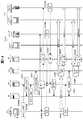
図17および図18は、本実施形態のIM-VoIP連携システムの第3の動作例である1対1の音声チャットから多者間の音声チャットへ移行する場合の動作を説明するための図である。
【0173】
ここでも、図10および図11に示す第1の動作例と同様に、ニックネーム「taro」を持つユーザは、テキストチャット機能および音声チャット機能の両方を備えたIP端末7-2(IMクライアントのアカウント名:client A)を用いてIMに参加し、ニックネーム「hanako」を持つユーザは、テキストチャット機能のみを備えたIP端末7-1(IMクライアントのアカウント名:client D)およびVoIP電話機8(IMクライアントのアカウント名:client E)を用いてIMに参加し、そして、ニックネーム「yoshi」を持つユーザは、テキストチャット機能のみを備えたIP端末7-3(IMクライアントのアカウント名:client F)および無線端末9(IMクライアントのアカウント名:client G)を用いてIMに参加しているものとする。また、IP端末7-1、7-3、VoIP電話機8および無線端末9は、IMサーバ4へのログイン処理が既に完了しているものとする。
【0174】
まず、図10のS1001〜S1005と同様の処理が行なわれ、IP端末7-2に搭載されたIMクライアントのログイン、IP端末7-2に搭載されたIMクライアントのプレゼンス情報のIMサーバ4へのアップロード、および、仲間のIMクライアントのプレゼンス情報のIMサーバ4からIP端末7-2へのダウンロードが行なわれる(S3001〜S3005)。
【0175】
さて、ユーザ「taro」は、IP端末7-2に表示された仲間のIMクライアントのプレゼンス情報を参照して、1対1で音声チャットを行なうIMクライアントを決定し、IMクライアントの指定(client E)を伴う音声チャット要求指示を入力したとする。IP端末7-2において、イベント解析部789は、これを検知して、データ/コマンド生成部792に、自身のIMクライアントおよび音声チャットを呼びかけるIMクライアントの諸情報(アカウント名、クライアントアドレス、クライアントニックネームなど)を含んだ音声チャット要求コマンドを生成させる。この音声チャット要求コマンドは、パケット生成部794にてIPパケット化され、IP網1を介して、プロファイルデータ686に登録されているアドレスより特定されるAPサーバ5へ送信される(S3006)。
【0176】
その後、図11のS1017〜S1023と同様の処理が行なわれる(S3007〜S3011)。しかし、ここでは、1対1の音声チャットを要求する音声チャット要求コマンドであるので、当該コマンドに含まれているIMクライアントの情報は2つである。このため、MDサーバ6で行なわれるミックス処理は、次のようになる。すなわち、2つのIMクライアント(「client A」、「client E」)から音声チャット用アドレスへ向けて送信された音声パケットは、パケット分解部881および解析・音声パケット/コマンド振分部882を介して、音声パケット分解部885に入力され、ヘッダ処理される。これにより、符号化された音声データが得られる。次に、デコーダ886にて符号化された音声データが復号化されて、ミキサ887に入力される。ミキサ887は、同じ音声チャット用アドレス向けに送信された音声パケットに関し、2つのIMクライアント毎に音声データを所定時間分バッファリングすると共に、一方のIMクライアントに対してバッファリングされた音声データを他方のIMクライアント向けの音声データとする処理を行なう。以上のようにして作成された音声データは、エンコーダ888にて復号化された後に、音声パケット生成部880にて音声パケット(VoIPパケット)化される。それから、パケット生成部890でIPパケット化されてIP網1へ送信される。これにより、2つのIMクライアント(「client A」、「client E」)間、つまり、ユーザ「taro」およびユーザ「hanako」間の音声チャットが実現される。
【0177】
ここで、ユーザ「taro」が、ユーザ「hanako」との1対1の音声チャットから多者間の音声チャットに切り替えたいと考え、IP端末7-2に、チャット仲間のプレゼンス情報のダウンロード要求を指示したとする。IP端末7-2において、イベント解析部789は、これを受けて、データ/コマンド生成部792に、チャット仲間のプレゼンス情報のダウンロード要求コマンドを生成させる。このダウンロード要求コマンドは、パケット生成部794にてIPパケット化され、IP網1を介して、プロファイルデータ686に登録されているアドレスより特定されるIMサーバ4へ送信される(S3012)。
【0178】
IMサーバ4において、コマンド処理部484は、パケット分解部481および解析・データ/コマンド振分部482を介して、IP端末7-2よりダウンロード要求コマンドを受け取ると、図10のS1005と同様の処理を行なって、バディリスト通知をIP端末7-2に送信する(S3013)。
【0179】
さて、ユーザ「taro」は、IP端末7-2に表示された仲間のIMクライアントのプレゼンス情報を参照して、ユーザ「hanako」との音声チャットに参加を呼びかけるユーザ「yoshi」のIMクライアント「client G」を決定し、IMクライアントの指定(client G)を伴う音声チャット要求指示を入力したとする。IP端末7-2において、イベント解析部789は、これを検知し、データ/コマンド生成部792に、音声チャットを呼びかけるIMクライアントの諸情報(アカウント名、クライアントアドレス、クライアントニックネームなど)と、IMクライアント「client E」との音声チャットに使用している音声チャット用アドレスとを含んだ音声チャット追加要求コマンドを生成させる。この音声チャット追加要求コマンドは、パケット生成部794にてIPパケット化され、IP網1を介して、プロファイルデータ686に登録されているアドレスより特定されるAPサーバ5へ送信される(S3014)。
【0180】
APサーバ5において、解析処理部582は、パケット分解部581を介して、音声チャット追加要求コマンドを受け取ると、コネクション管理テーブル586を参照して、この音声チャット追加要求コマンドに含まれている音声チャット用アドレスがフィールド535に登録されているレコード540の、フィールド534に登録されている符号化方式を特定する。そして、出力データ生成部583に、音声チャット追加要求コマンドに含まれているIMクライアントのアドレス(この場合、IMクライアントが無線端末9に搭載されているので、VRサーバ10のアドレス)と、音声チャット追加要求コマンドに含まれている音声チャット用アドレスと、特定した音声信号の符号化方式と、を含んだミキシング追加設定要求コマンドを生成させる。このミキシング追加設定要求コマンドは、パケット生成部584にてIPパケット化され、IP網1を介して、MDサーバ6に送信される(S3015)。
【0181】
MDサーバ6において、コマンド処理部883は、パケット分解部881および解析・音声パケット/コマンド振分部882を介して、ミキシング追加設定要求コマンドを受け取ると、この追加設定要求コマンドに含まれているアドレスを持つIMクライアントが、この追加設定要求コマンドに含まれている音声チャット用アドレスを用いて行なわれている音声チャットに参加できるように、音声パケット分解部885、デコーダ886、ミキサ887および音声パケット生成部889の設定を行なう。
【0182】
一方、APサーバ5において、解析処理部582は、出力データ生成部583に、IP端末7-2より受け取った音声チャット追加要求コマンドに含まれているアドレスより特定されるIMクライアントに対する音声チャット呼出しコマンドを生成させる。この音声チャット呼出しコマンドには、音声チャット用アドレスを含める。この音声チャット呼出しコマンドは、パケット生成部584でIPパケット化され、IP網1を介して、音声チャット追加要求コマンドに含まれているアドレスより特定されるIMクライアントへ送信される(S3016)。
【0183】
ここで、送信先のIMクライアントが無線端末9に搭載されているので、音声チャット呼出しコマンドに、音声チャット用アドレスに加え、このIMクライアントが搭載された無線端末9の電話番号等をさらに含める。そして、音声チャット呼出しコマンドは、クライアントアドレスとして無線端末9の電話番号等と共に登録されているアドレスより特定されるVRサーバ10へ送信される。VRサーバ10において、呼制御処理部987は、APサーバ5より音声チャット呼出しコマンドを受け取ると、この呼出しコマンドに含まれている電話番号等より特定される無線端末9に電話をかけて呼び出す(S3016)。
【0184】
その後、図10のS1019、S1020C、S1021およびS1022と同様の処理が行なわれ、設定完了コマンドがAPサーバ5からIMサーバ4へ送信される(S3017〜S3020)。これにより、3つのIMクライアント(「client A」、「client E」、「client G」)間、つまり、ユーザ「taro」、ユーザ「hanako」およびユーザ「yoshi」間の音声チャットが実現される(S3021、S3022)。
【0185】
次に、本実施形態のIM-VoIP連携システムの第4の動作例として、カンファレンスルームを閉鎖する場合の動作を説明する。
【0186】
図19は、本実施形態のIM-VoIP連携システムの第4の動作例であるカンファレンスルームを閉鎖する場合の動作を説明するための図である。
【0187】
さて、図10に示すS1001〜S1012と同様の処理が行なわれ、3つのIMクライアント(「client A」、「client D」、「client F」)間、つまり、ユーザ「taro」、ユーザ「hanako」およびユーザ「yoshi」間でテキストチャットが行なわれているとする(S4001)。
【0188】
さて、IP端末7-2において、イベント解析部789は、ユーザ「taro」よりカンファレンスルームからの退室指示を受け取ると、データ/コマンド生成部792に、自身のIMクライアントの情報(アカウント名やアドレス)を含んだカンファレンス退室要求コマンドを生成させる。この退室要求コマンドは、パケット生成部794にてIPパケット化され、プロファイルデータ686に登録されているアドレスより特定されるIMサーバ4へ送信される(S4002)。
【0189】
IMサーバ4において、コマンド処理部484は、パケット分解部481および解析・データ/コマンド振分部482を介してカンファレンス退室要求コマンドを受け取ると、コネクション管理部487にこれを通知する。
【0190】
コネクション管理部487は、カンファレンス退室要求コマンドに含まれているIMクライアントの情報(アカウント名やクライアントアドレス)を持つレコード440を、プレゼンス情報管理テーブル488から特定する。そして、特定したレコード440に登録されているカンファレンスルームに関する情報(フィールド435に登録されているテキストチャット中であることを示すプレゼンス情報、フィールド437に登録されているカンファレンスルームのアドレス、および、フィールド438に登録されているカンファレンスニックネーム)を削除する。その結果、対応するIMクライアントがチャット中の状態でなくなったならば、フィールド435にアイドル状態であることを示す情報を登録する。
【0191】
また、コネクション管理部487は、データ処理部483を制御し、カンファレンス退室要求コマンドに含まれているIMクライアント「client A」に対するテキストデータの合成および配信処理を中止する。その結果、IP端末7-1(IMクライアント「client D」)およびIP端末7-3(IMクライアント「client F」)間でのみテキストチャットが行なわれることになる(S4003)。なお、IP端末7-1およびIP端末7-2がテキストチャットを終了する場合も、IP端末7-2の場合と同様の処理が行なわれる(S4004)。そして、全てのIMクライアントがカンファレンスルームから退室することで、プレゼンス情報管理テーブル488からこのカンファレンスルームに割り当てていたアドレスが削除され、このアドレスが解放される。
【0192】
以上、本発明の一実施形態について説明した。
【0193】
本実施形態のIM-VoIP連携システムでは、IMクライアントのプレゼンス情報を管理するIMサーバ4と、VoIPを利用した音声チャットのためのコネクションを管理するAPサーバ5と、音声データのミキシングを行なって多者音声通話を実現するためのMDサーバ6とを設けている。
【0194】
そして、IMサーバ4に、各IMクライアントのプレゼンス情報と共に、各IMクライアントのチャットに利用可能なメディアの情報および各クライアントのユーザの情報(ニックネーム)をも管理させ、各IMクライアントが、これらの情報を取得できるようにしている。このため、各IMクライアントのユーザは、各IMクライアントがチャットに利用できるメディアと、各IMクライアントのユーザとを確認できる。これにより、仲間のユーザが、どのIMクライアントを用いてどのようなチャット(テキストチャットおよび音声チャット)をできるのかを確認することができる。
【0195】
また、テキストチャットを行なう場合、IMクライアントがテキストチャットに参加する各IMクライアントの情報をIMサーバ4に通知する。これを受けて、IMサーバ4は、テキストチャットに参加する各IMクライアントとIMサーバ4との間のコネクションを管理し、各IMクライアントから送られてきたテキストメッセージをマージして、その結果を各IMクライアントに配信する。
【0196】
一方、音声チャットを行なう場合、IMクライアントが、あるいは、IMクライアントの代理としてIMサーバが、音声チャットに参加する各IMクライアントの情報をAPサーバ5に通知する。これを受けて、APサーバ5は、音声チャットに参加する各IMクライアントとMDサーバ6との間のコネクションを管理する。MDサーバ6は、注目IMクライアントを除く各IMクライアントから送られてきた音声データをミックスして、その結果を注目IMクライアントに配信する処理を、音声チャットに参加する全てのIMクライアントに対して行なう。
【0197】
したがって、本実施形態によれば、テキストチャットおよび音声チャットの両方を利用でき、また、テキストチャットおよび音声チャット間の移行や、1対1チャットおよびグループチャット間の移行を柔軟に行なうことがきる。このように、本実施形態によれば、コミュニケーションシステムの使い勝手が向上する。
【0198】
なお、本発明は上記の実施形態に限定されるものではなく、その要旨の範囲内で数々の変形が可能である。
【0199】
例えば、上記の実施形態では、IMサーバ4、APサーバ5およびMDサーバ6のそれぞれを、異なるコンピュータシステム上に構築した場合を例に取り説明した。しかし、本発明はこれに限定されない。APサーバ5およびMDサーバ6を1つのコンピュータシステム上に構築してもよいし、あるいは、コンピュータシステムがネットワーク接続されて構成されたネットワークシステム上に構築してもよい。また、IMサーバ4を、APサーバ5およびMDサーバ6が構築されたコンピュータシステム上に、構築するようにしてもかまわない。
【0200】
また、上記の実施形態では、チャットに利用するメディアとして、音声チャットおよびテキストチャットを想定している。しかし、本発明はこれに限定されない。本発明は、映像を用いたチャットにも利用できる。なお、映像チャットの仕組みは、上述した音声チャットのための仕組みを適用できる。
【0201】
【発明の効果】
以上説明したように、本発明によれば、コミュニケーションシステムの使い勝手を向上させることができる。
【図面の簡単な説明】
【図1】本発明の一実施形態が適用されたコミュニケーションシステムであるIM-VoIP(Voice over Internet Protocol)連携システムの概略図である。
【図2】図1に示すIMサーバ4の概略構成図である。
【図3】図2に示すコネクション管理部487がプレゼンス情報を管理するために用いるプレゼンス情報管理テーブル488の一例を示す図である。
【図4】図1に示すAPサーバ5の概略構成図である。
【図5】図4に示すコネクション管理部585が音声チャットを管理するために用いるVoIPコネクション管理テーブル586の一例を示す図である。
【図6】図1に示すIP端末7の概略構成図である。
【図7】IMクライアントがIMに参加するために必要なプロファイルデータ686の一例を示す図である。
【図8】図1に示すMDサーバ6の概略構成図である。
【図9】図1に示すVRサーバ10の概略構成図である。
【図10】本発明の一実施形態のIM-VoIP連携システムの第1の動作例であるテキストチャットから音声チャットに移行する場合の動作を説明するための図である。
【図11】本発明の一実施形態のIM-VoIP連携システムの第1の動作例であるテキストチャットから音声チャットに移行する場合の動作を説明するための図である。
【図12】IP端末7に表示されるIMクライアントのユーザインタフェース例を示す図である。
【図13】図11に示す第1の動作例の変形例を説明するための図である。
【図14】図11に示す第1の動作例の変形例を説明するための図である。
【図15】本発明の一実施形態のIM-VoIP連携システムの第2の動作例である音声チャット中にテキストチャットを併用する場合の動作を説明するための図である。
【図16】本発明の一実施形態のIM-VoIP連携システムの第2の動作例である音声チャット中にテキストチャットを併用する場合の動作を説明するための図である。
【図17】本発明の一実施形態のIM-VoIP連携システムの第3の動作例である1対1の音声チャットから多者間の音声チャットへ移行する場合の動作を説明するための図である。
【図18】本発明の一実施形態のIM-VoIP連携システムの第3の動作例である1対1の音声チャットから多者間の音声チャットへ移行する場合の動作を説明するための図である。
【図19】本発明の一実施形態のIM-VoIP連携システムの第4の動作例であるカンファレンスルームを閉鎖する場合の動作を説明するための図である。
【符号の説明】
1:IP網、2:無線通信網、3:公衆電話網、4:IMサーバ、5:APサーバ、6:MDサーバ、7:IP端末、8:VoIP電話機、9:無線端末、10:VRサーバ、11:固定電話機、41:CPU、42:メモリ、43:外部記憶装置、44:入力装置、45:出力装置、46:IP網IF、47:バス、48:通信装置、481:パケット分解部、482:解析・データ/コマンド振分部、483:データ処理部、484:コマンド処理部、485:出力データ生成部、486:パケット生成部、487:コネクション管理部、488:プレゼンス情報管理テーブル、581:パケット分解部、582:解析・処理部、583:出力データ生成部、584:パケット生成部、585:コネクション管理部、586:コネクション管理テーブル、686:プロファイルデータ、781:パケット分解部、782:解析・音声パケット/データ/コマンド振分部、783:データ処理部、784:コマンド処理部、785:音声パケット分解部、786:出力データ生成部、787:デコーダ、788:D/A変換部、789:イベント解析部、790:A/D変換部、791:エンコーダ、792:データ/コマンド生成部、793:音声パケット生成部、794:パケット生成部、881:パケット分解部、882:解析・音声パケット/コマンド振分部、883:コマンド処理部、884:出力データ生成部、885:音声パケット分解部、886:デコーダ、887:ミキサ、888:エンコーダ、889:音声パケット生成部、890:パケット生成部、981:パケット分解部、982:音声パケット分解部、983:デコーダ、984:エンコーダ、985:音声パケット生成部、986:パケット生成部、987:呼制御処理部[0001]
BACKGROUND OF THE INVENTION
The present invention relates to a communication technology such as IM (Instant Messaging).
[0002]
[Prior art]
Communication technology called IM is attracting attention. If you want to talk to the other party, it's not as much as a call, but if you're an email, you don't know when the other party will read the email (when the reply will come back). IM has this intermediate temporal characteristic. IM discloses its current status (called presence information) such as online / offline and response availability. Thereby, the tool used for communication with friends, such as chat and an email, can be selected according to the presence information of the friends who are using the same IM system on the Internet.
[0003]
Currently, IM systems are released from many vendors, and IM clients that are application software for using the IM systems are distributed. However, the IM system is not compatible between vendors, and therefore, communication cannot be performed between IM clients of different vendors. Therefore, standardization work was started from the request of interoperability, and IMPF (Instant Messaging & Presence Protocol) working group of IETF (Internet Engineering Task Force) related to IM, architecture, message integration, security (authentication, encryption, etc.) Has been discussed. RFC (Require for Comment) 2778 defines a model, and RFC 2779 defines a protocol requirement.
[0004]
Conventionally, the multi-person connection (group chat) by IM has been mainly used for hobby use like a well-end conference. In recent years, however, business use of group chatting has begun to be considered. Here, it is speculated that there are many cases where text-based group chat is insufficient for business use. Japanese input takes time. Also, in order to express nuances that are difficult to convey in complicated stories and documents, voice support is required. One-to-one (Peer-to-Peer) has begun to develop communication using multimedia. References 1 (Nikkei Communication 2001) are used for voice chat and file exchange. / 11/5 p.106-p.113).
[0005]
[Problems to be solved by the invention]
When communication technology is applied to business use, it is desirable to be able to easily handle not only text but also audio at the conference, in addition to being able to participate in the conference while at the seat and being able to participate in the conference at the destination.
[0006]
However, the conventional IM system does not support multimedia group chat. In the system described in the
[0007]
There is a video conference system as a technique for realizing group chat other than the IM system. However, the conventional video conference system needs to be gathered in a room such as a video conference room at the scheduled time of the conference, or the user needs to call a virtual conference room set in advance. It lacked the ability.
[0008]
The present invention has been made in view of the above circumstances, and an object of the present invention is to improve the usability of a communication system. Specifically, it is to be able to handle multimedia group chat. For example, it is possible to flexibly handle a transition between a group chat based on an electronic document and a voice group chat, and a transition between a voice one-to-one chat and a voice group chat.
[0009]
[Means for Solving the Problems]
In order to solve the above-described problem, in the present invention, an IM presence management server that manages presence information representing the status of an IM client, a VoIP communication connection management server that manages a connection for voice chat using VoIP, and a voice A chat between IM clients is realized using a media server for performing multi-party voice communication by mixing data.
[0010]
For example, for each IM client, the IM presence management server manages presence information of the IM client, information on media (including text and voice) that the IM client can use for chatting, and user information of the IM client. In accordance with an instruction from the IM client, the IM client is presented with presence information, usable media information, and user information of each IM client set as a member of the IM client.
[0011]
The IM presence management server manages the connection between each text participating client and the IM presence management server according to the information of each IM client (referred to as a text participating client) participating in the text chat notified from the IM client. The text data sent from each text participating client is merged, and the result is distributed to each text participating client.
[0012]
The VoIP communication connection management server is connected to each voice participation client and the media server according to information of each IM client (referred to as a voice participation client) participating in the voice chat notified from the IM client or the IM presence management server. Manage.
[0013]
The media server, when a certain voice participation client is the client of interest, mixes the audio data sent from each voice participant client except the client of interest, and distributes the result to the client of interest, Perform for all voice participating clients.
[0014]
DETAILED DESCRIPTION OF THE INVENTION
Embodiments of the present invention will be described below.
[0015]
FIG. 1 is a schematic diagram of an IM-VoIP (Voice over Internet Protocol) linkage system which is a communication system to which an embodiment of the present invention is applied.
[0016]
As shown in the figure, an
[0017]
In the above configuration, the IP terminals 7-1 to 7-3 use the
[0018]
Next, each device constituting the IM-VoIP cooperation system will be described.
[0019]
First, the
[0020]
As described above, the
[0021]
As illustrated, the
[0022]
The
[0023]
The analysis / data /
[0024]
The
[0025]
The
[0026]
The output
[0027]
The
[0028]
The
[0029]
Note that the
[0030]
FIG. 3 shows an example of a presence information management table 488 used by the
[0031]
As shown, a
[0032]
Here, in the
[0033]
In the
[0034]
In the
[0035]
When the user uses a plurality of IM clients, for example, when the client terminal 7-1 is used for text chat and the
[0036]
Next, the AP server 5 will be described.
[0037]
As described above, the AP server 5 manages a connection for voice chat using VoIP. FIG. 4 shows a schematic configuration of the AP server 5.
[0038]
As shown in the figure, in the computer system having the same hardware configuration as the
[0039]
The
[0040]
The analysis /
[0041]
The output
[0042]
The
[0043]
The
[0044]
Note that the
[0045]
FIG. 5 shows an example of a VoIP connection management table 586 used by the
[0046]
As shown, a
[0047]
Next, the IP terminal 7 will be described.
[0048]
As described above, the IP terminal 7 is equipped with an IM client for enjoying chatting. FIG. 6 shows a schematic configuration of the IP terminal 7.
[0049]
As shown in the figure, in the computer system having the same hardware configuration as that of the
[0050]
The
[0051]
The analysis / voice packet / data /
[0052]
The
[0053]
The
[0054]
The output
[0055]
The voice
[0056]
The
[0057]
The D /
[0058]
The A /
[0059]
The
[0060]
The voice
[0061]
The
[0062]
The data /
[0063]
The
[0064]
Note that the
[0065]
FIG. 7 shows an example of profile data 686 necessary for an IM client to participate in IM. The profile data 686 is stored in the
[0066]
As illustrated, a nickname of the IM client user is registered in the
[0067]
The
[0068]
When only text chat is performed at the IP terminal 7 and voice chat is performed using the
[0069]
Next, the MD server 6 will be described.
[0070]
As described above, the MD server 6 performs a multi-party voice call by mixing voice data. FIG. 8 shows a schematic configuration of the MD server 6.
[0071]
As shown in the figure, the MD server 6 is a computer system having the same hardware configuration as that of the
[0072]
The
[0073]
The analysis / voice packet /
[0074]
The
[0075]
The output
[0076]
The voice
[0077]
The
[0078]
The
[0079]
The
[0080]
The voice
[0081]
The
[0082]
Note that the
[0083]
Next, the
[0084]
As described above, the
[0085]
As shown in the figure, the
[0086]
The
[0087]
The voice
[0088]
The
[0089]
Audio data received from the communication partner via the
[0090]
The voice
[0091]
The
[0092]
The call
[0093]
Note that the
[0094]
Next, the operation of the IM-VoIP cooperation system having the above configuration will be described.
[0095]
First, as a first operation example of the IM-VoIP linkage system according to the present embodiment, a case where a text chat is switched to a voice chat will be described.
[0096]
FIG. 10 and FIG. 11 are diagrams for explaining the operation when shifting from text chat to voice chat, which is the first operation example of the IM-VoIP linkage system of the present embodiment.
[0097]
In this example, a user having the nickname “taro” has an IP terminal 7-2 (IM client) having both a text chat function and a voice chat function (all function blocks 781 to 794 in the balloon frame 78 in FIG. 6). The user with the nickname “hanako” who participates in the IM with the account name: client A) has only the text chat function (function blocks 781 to 784, 786, 789, 792 and 794 in the balloon frame 78 of FIG. 6). ) With an IP terminal 7-1 (IM client account name: client D) and a VoIP telephone 8 (IM client account name: client E) and a user with the nickname “yoshi” IP terminal 7-3 with only text chat function (IM client account name: client F) And wireless terminal 9 (IM client's account name: client G) assumed to participate in the IM using.
[0098]
10 and 11, it is assumed that the login processing to the
[0099]
First, in the IP terminal 7-2, the
[0100]
In the
[0101]
In the IP terminal 7-2, when the
[0102]
In the
[0103]
Next, in the IP terminal 7-2, the
[0104]
In the
[0105]
In the IP terminal 7-2, when the
[0106]
As described above, the user “taro” can know the presence information, available media, and participating conference rooms of chat friends based on the information included in the buddy list notification. Here, it is assumed that the user “taro” inputs a new conference room opening instruction to the
[0107]
In the
[0108]
In the IP terminal 7-2, the
[0109]
In the
[0110]
In the IP terminal 7-2, when the
[0111]
In the IP terminal 7-2, when the
[0112]
In the
[0113]
Next, the
[0114]
In the IP terminal 7-1, when the
[0115]
In the IP terminal 7-1, when the
[0116]
In the
[0117]
In response to this, the
[0118]
In addition, the
[0119]
Specifically, the
[0120]
At this time, each IP terminal 7 performs the following processing. That is, when a message is input from the user, the
[0121]
In the IP terminal 7-2, when the
[0122]
In the
[0123]
Then, the
[0124]
In the IP terminal 7-2, when the
[0125]
Now, the user “taro”, the information of the buddy list displayed on the display device and the exchange through the text chat, the users “hanako” and “yoshi” participating in the conference are “client E”, Assume that it is confirmed that an IM client (
[0126]
In the IP terminal 7-2, the
[0127]
In the AP server 5, when the
[0128]
In the MD server 6, when the
[0129]
On the other hand, in the AP server 5, the
[0130]
Here, when the destination IM client is mounted on the wireless terminal 9 and the fixed
[0131]
As described above, each IM client designated by the voice chat request is called by the AP server 5. In the IP terminal 7-2, the calling command reaches the
[0132]
In the AP server 5, when the analysis /
[0133]
In the
[0134]
When the above processing is completed, a voice chat connection is established between the MD server 6 and each IM client (IP terminal 7-2,
[0135]
Specifically, a voice packet transmitted from each IM client to the voice chat address is input to the voice
[0136]
At this time, the following processing is performed in the IP terminal 7-2. That is, an analog audio signal representing the audio input by the user is converted into a digital audio signal by the A /
[0137]
The
[0138]
In the IP terminal 7-2, when the
[0139]
In the AP server 5, when the analysis /
[0140]
In the
[0141]
In the MD server 6, when the
[0142]
FIG. 12 shows an example of a user interface of the IM client displayed on the IP terminal 7.
[0143]
[0144]
When the user selects the
[0145]
[0146]
[0147]
Next, a modification of the first operation example will be described.
[0148]
FIG. 13 is a diagram for explaining a modification of the first operation example described above, and is a diagram for explaining an operation of a portion corresponding to FIG. The operation corresponding to FIG. 10 is the same as that in the first operation example.
[0149]
In the first embodiment described above, as shown in FIG. 11, when the
[0150]
On the other hand, in this modification, as shown in FIG. 13, when the
[0151]
Here, identification of a fellow IM client capable of voice chat may be performed as follows. First, for each of the fellow IM clients in the text chat, it is confirmed whether or not the used media registered in the
[0152]
Next, another modification of the first operation example will be described.
[0153]
FIG. 14 is a diagram for explaining another modification of the first operation example described above, and is a diagram for explaining an operation of a portion corresponding to FIG. The operation corresponding to FIG. 10 is the same as that in the first operation example.
[0154]
In the first embodiment described above, as shown in FIG. 11, the IP terminal 7-2 transmits a buddy list request command to the IM server 4 (S1014) and includes the presence information of the buddy in the text chat. The buddy list is received from the IM server 4 (S1015). Then, the IP terminal 7-2 creates a voice chat request command including information on the IM client that performs voice chat, and transmits this command to the AP server 5 (S1016).
[0155]
On the other hand, in this modified example, as shown in FIG. 14, the IP terminal 7-2 suddenly sends a voice chat request command including information on its own IM client and conference room information to the AP server 5. (S1014b). Then, the AP server 5 creates a buddy list request command including information on the IM client of the IP terminal 7-2 and information on the conference room, and transmits it to the IM server 4 (S1015c). When the
[0156]
Next, as a second operation example of the IM-VoIP linkage system of the present embodiment, a case where text chat is used together during voice chat will be described.
[0157]
FIG. 15 and FIG. 16 are diagrams for explaining an operation when a text chat is used together during a voice chat, which is a second operation example of the IM-VoIP cooperation system of the present embodiment.
[0158]
Here, similarly to the first operation example shown in FIG. 10 and FIG. 11, the user having the nickname “taro” has the IP terminal 7-2 (IM client account) having both the text chat function and the voice chat function. A user who participates in IM using a name: client A) and has a nickname “hanako”, an IP terminal 7-1 (IM client account name: client D) and a VoIP telephone 8 (IM The user who participates in IM using the client account name: client E), and the user with the nickname “yoshi” has an IP terminal 7-3 (IM client account name: client F) and only a text chat function. It is assumed that the wireless terminal 9 (IM client account name: client G) is used to participate in IM. Further, it is assumed that the login processing to the
[0159]
First, the same processing as S1001 to S1005 in FIG. 10 is performed, and the login of the IM client mounted on the IP terminal 7-2, the upload of the presence information of this IM client to the
[0160]
Now, the user “taro” refers to the presence information of the fellow IM client displayed on the IP terminal 7-2, determines the IM client for voice chat, and specifies the IM client (client E, client G). Suppose that a voice chat request instruction with is input. In the IP terminal 7-2, the
[0161]
Thereafter, processing similar to S1017 to S1024 in FIG. 11 is performed, and the IM client “client A” installed in the IP terminal 7-2, the IM client “client E” installed in the
[0162]
In the IP terminal 7-2, when the
[0163]
In the
[0164]
Then, the
[0165]
In the IP terminal 7-2, when the
[0166]
As a result, the user “taro” can determine whether or not the friend in the voice chat is capable of text chat through the friend information displayed on the display device and the voice chat in progress, and if the text chat is possible. It is possible to check which IM client (identified by account name and client nickname) is used for text chat. Then, it is possible to confirm whether or not a conference room for text chat can be set as an auxiliary for voice chat.
[0167]
Now, the user “taro”, who is participating in the voice chat through the information of the fellows displayed on the display device and the voice chat, the users “hanako” and “yoshi” are “client D” and “client F”, respectively. It is assumed that it is confirmed that the user can participate in the text chat using the IM client (IP terminal 7-1, IP terminal 7-3) having the account name "and has an intention to participate in the text chat." It is assumed that an instruction for opening a new conference room for the text chat is input to the
[0168]
Then, in the IP terminal 7-2, the
[0169]
Thereafter, in the IP terminal 7-2, when the
[0170]
In addition, the process (S2026-S2029) in the case of complete | finishing a voice chat is the same as that of S1025-S1024 shown in FIG.
[0171]
Next, as a third operation example of the IM-VoIP cooperation system according to the present embodiment, an operation in the case of shifting from a one-to-one voice chat to a multi-party voice chat will be described.
[0172]
FIG. 17 and FIG. 18 are diagrams for explaining the operation in the case of shifting from the one-to-one voice chat, which is the third operation example of the IM-VoIP cooperation system of the present embodiment, to the voice chat between multiple parties. is there.
[0173]
Here, similarly to the first operation example shown in FIG. 10 and FIG. 11, the user having the nickname “taro” has the IP terminal 7-2 (IM client account) having both the text chat function and the voice chat function. A user who participates in IM using a name: client A) and has a nickname “hanako”, an IP terminal 7-1 (IM client account name: client D) and a VoIP telephone 8 (IM The user who participates in IM using the client account name: client E), and the user with the nickname “yoshi” has an IP terminal 7-3 (IM client account name: client F) and only a text chat function. It is assumed that the wireless terminal 9 (IM client account name: client G) is used to participate in IM. Further, it is assumed that the login processing to the
[0174]
First, the same processing as S1001 to S1005 in FIG. 10 is performed, and the login of the IM client installed in the IP terminal 7-2 and the presence information of the IM client installed in the IP terminal 7-2 to the
[0175]
Now, the user “taro” refers to the presence information of the companion IM client displayed on the IP terminal 7-2, determines the IM client that performs a one-to-one voice chat, and specifies the IM client (client E ) Voice chat request instruction is input. In the IP terminal 7-2, the
[0176]
Thereafter, processing similar to S1017 to S1023 in FIG. 11 is performed (S3007 to S3011). However, here, since it is a voice chat request command for requesting a one-to-one voice chat, the IM client information included in the command is two. For this reason, the mixing process performed by the MD server 6 is as follows. That is, voice packets transmitted from two IM clients (“client A” and “client E”) to the voice chat address are sent via the
[0177]
Here, the user “taro” wants to switch from the one-to-one voice chat with the user “hanako” to the multi-party voice chat, and requests the IP terminal 7-2 to download the presence information of the chat fellow. Assume that you have instructed. In the IP terminal 7-2, the
[0178]
In the
[0179]
Now, the user “taro” refers to the presence information of the fellow IM client displayed on the IP terminal 7-2 and refers to the IM client “client” of the user “yoshi” who calls for participation in the voice chat with the user “hanako”. Suppose that “G” is determined and a voice chat request instruction with IM client designation (client G) is input. In the IP terminal 7-2, the
[0180]
In the AP server 5, when the
[0181]
In the MD server 6, when the
[0182]
On the other hand, in the AP server 5, the
[0183]
Here, since the destination IM client is mounted on the wireless terminal 9, the voice chat call command further includes the telephone number of the wireless terminal 9 mounted with this IM client in addition to the voice chat address. Then, the voice chat call command is transmitted to the
[0184]
Thereafter, processing similar to S1019, S1020C, S1021 and S1022 in FIG. 10 is performed, and a setting completion command is transmitted from the AP server 5 to the IM server 4 (S3017 to S3020). As a result, a voice chat between the three IM clients (“client A”, “client E”, “client G”), that is, between the user “taro”, the user “hanako”, and the user “yoshi” is realized ( S3021, S3022).
[0185]
Next, as a fourth operation example of the IM-VoIP cooperation system of the present embodiment, an operation when closing a conference room will be described.
[0186]
FIG. 19 is a diagram for explaining an operation in the case of closing a conference room, which is a fourth operation example of the IM-VoIP cooperation system of the present embodiment.
[0187]
Now, the same processing as S1001 to S1012 shown in FIG. 10 is performed, and between three IM clients (“client A”, “client D”, “client F”), that is, user “taro” and user “hanako”. Further, it is assumed that a text chat is being performed between the user “yoshi” (S4001).
[0188]
In the IP terminal 7-2, when the
[0189]
In the
[0190]
The
[0191]
In addition, the
[0192]
The embodiment of the present invention has been described above.
[0193]
In the IM-VoIP cooperation system of this embodiment, the
[0194]
Then, the
[0195]
When performing text chat, the IM client notifies the
[0196]
On the other hand, when voice chat is performed, the IM client notifies the AP server 5 of the information of each IM client participating in the voice chat by the IM client or on behalf of the IM client. In response to this, the AP server 5 manages the connection between each IM client participating in the voice chat and the MD server 6. The MD server 6 mixes the voice data sent from each IM client excluding the IM client of interest and distributes the result to the IM client of interest to all IM clients participating in the voice chat. .
[0197]
Therefore, according to the present embodiment, both text chat and voice chat can be used, and transition between text chat and voice chat and transition between one-to-one chat and group chat can be performed flexibly. Thus, according to this embodiment, the usability of the communication system is improved.
[0198]
In addition, this invention is not limited to said embodiment, Many deformation | transformation are possible within the range of the summary.
[0199]
For example, in the above embodiment, the case where each of the
[0200]
In the above embodiment, voice chat and text chat are assumed as media used for chat. However, the present invention is not limited to this. The present invention can also be used for chatting using video. As the video chat mechanism, the voice chat mechanism described above can be applied.
[0201]
【The invention's effect】
As described above, according to the present invention, usability of the communication system can be improved.
[Brief description of the drawings]
FIG. 1 is a schematic diagram of an IM-VoIP (Voice over Internet Protocol) cooperation system, which is a communication system to which an embodiment of the present invention is applied.
FIG. 2 is a schematic configuration diagram of an
3 is a diagram showing an example of a presence information management table 488 used by the
4 is a schematic configuration diagram of an AP server 5 shown in FIG. 1. FIG.
5 is a diagram showing an example of a VoIP connection management table 586 used by the
6 is a schematic configuration diagram of an IP terminal 7 shown in FIG. 1. FIG.
FIG. 7 is a diagram showing an example of profile data 686 necessary for an IM client to participate in IM.
FIG. 8 is a schematic configuration diagram of the MD server 6 shown in FIG. 1;
FIG. 9 is a schematic configuration diagram of the
FIG. 10 is a diagram for explaining an operation in the case of shifting from text chat to voice chat, which is a first operation example of the IM-VoIP cooperation system according to the embodiment of the present invention;
FIG. 11 is a diagram for explaining an operation in the case of shifting from text chat to voice chat, which is a first operation example of the IM-VoIP cooperative system according to the embodiment of the present invention;
12 is a diagram illustrating an example of a user interface of an IM client displayed on the IP terminal 7. FIG.
FIG. 13 is a diagram for explaining a modification of the first operation example shown in FIG. 11;
FIG. 14 is a diagram for explaining a modification of the first operation example shown in FIG. 11;
FIG. 15 is a diagram for explaining an operation when a text chat is used together during a voice chat, which is a second operation example of the IM-VoIP linkage system according to the embodiment of the present invention;
FIG. 16 is a diagram for explaining an operation when a text chat is used together during a voice chat, which is a second operation example of the IM-VoIP linkage system according to the embodiment of the present invention;
FIG. 17 is a diagram for explaining an operation in the case of shifting from one-to-one voice chat to multi-party voice chat, which is a third operation example of the IM-VoIP linkage system according to the embodiment of the present invention; is there.
FIG. 18 is a diagram for explaining an operation in the case of shifting from a one-to-one voice chat to a multi-party voice chat, which is a third operation example of the IM-VoIP linkage system according to the embodiment of the present invention; is there.
FIG. 19 is a diagram for explaining an operation in the case of closing a conference room which is a fourth operation example of the IM-VoIP cooperation system according to the embodiment of the present invention;
[Explanation of symbols]
1: IP network, 2: wireless communication network, 3: public telephone network, 4: IM server, 5: AP server, 6: MD server, 7: IP terminal, 8: VoIP telephone, 9: wireless terminal, 10: VR Server: 11: Fixed telephone, 41: CPU, 42: Memory, 43: External storage device, 44: Input device, 45: Output device, 46: IP network IF, 47: Bus, 48: Communication device, 481: Packet decomposition 482: Analysis / data / command distribution unit 483: Data processing unit 484: Command processing unit 485: Output data generation unit 486: Packet generation unit 487: Connection management unit 488: Presence information management table 582: Packet decomposition unit 582: Analysis / processing unit 583: Output data generation unit 584: Packet generation unit 585: Connection management unit 586: Connection Management table, 686: profile data, 781: packet decomposition unit, 782: analysis / voice packet / data / command distribution unit, 783: data processing unit, 784: command processing unit, 785: voice packet decomposition unit, 786: output Data generator, 787: Decoder, 788: D / A converter, 789: Event analyzer, 790: A / D converter, 791: Encoder, 792: Data / command generator, 793: Voice packet generator, 794 : Packet generation unit, 881: packet decomposition unit, 882: analysis / voice packet / command distribution unit, 883: command processing unit, 884: output data generation unit, 885: voice packet decomposition unit, 886: decoder, 887: mixer 888: Encoder 889: Voice packet generator 890: Packet generator 981: Packet Decomposition unit, 982: voice packet decomposing portion, 983: Decoder, 984: Encoder, 985: voice packet generation unit, 986: a packet generation unit, 987: a call control processor
Claims (11)
Translated fromJapaneseIMクライアントの状況を表すプレゼンス情報を管理するIMプレゼンス管理サーバと、VoIP(Voice over Internet Protocol)を利用した音声チャットのためのコネクションを管理するVoIP通信コネクション管理サーバと、音声データのミキシングを行なって多者音声通話を実現するためのメディアサーバとを有し、
前記IMプレゼンス管理サーバは、
IMクライアント毎に、IMクライアントのプレゼンス情報、IMクライアントがチャットに利用可能なメディア(テキストおよび音声を含む)の情報、および、IMクライアントのユーザ情報を管理すると共に、IMクライアントからの指示に従い、当該IMクライアントに、当該IMクライアントの仲間に設定されているIMクライアント各々のプレゼンス情報、利用可能なメディアの情報およびユーザ情報を提示する手段と、
また、IMクライアントから通知されたテキストチャットに参加する各IMクライアント(テキスト参加クライアントと呼ぶ)の情報に従い、各テキスト参加クライアントおよび前記IMプレゼンス管理サーバ間のコネクションを管理し、各テキスト参加クライアントから送られてきたテキストデータをマージして、その結果を各テキスト参加クライアントに配信する手段と、を有し、
前記VoIP通信コネクション管理サーバは、
IMクライアントあるいは前記IMプレゼンス管理サーバから通知された音声チャットに参加する各IMクライアント(音声参加クライアントと呼ぶ)の情報に従い、各音声参加クライアントおよび前記メディアサーバ間のコネクションを管理する手段、を有し、
前記メディアサーバは、
ある音声参加クライアントを注目クライアントとした場合に、注目クライアントを除く各音声参加クライアントから送られてきた音声データをミックスして、その結果を注目クライアントに配信する処理を、全ての音声参加クライアントに対して行なう手段、を有し、
前記VoIP通信コネクション管理サーバが、各音声参加クライアントおよび前記メディアサーバ間のコネクションを管理しており、かつ、前記メディアサーバが、音声参加クライアントから送られてきた音声データの他の音声参加クライアントよりの音声データをミックスして、その結果を注目クライアントに配信している間に、音声参加クライアントのうち1つ(以下、第1のIMクライアント)からの指示を受けた場合、
前記IMプレゼンス管理サーバは、
前記第1のIMクライアントに、当該第1のIMクライアントの仲間に設定されているIMクライアント各々のプレゼンス情報、利用可能なメディアの情報およびユーザ情報を提示し、
前記第1のIMクライアントからテキスト参加クライアントが通知されると、該テキスト参加クライアントの情報に従い、各テキスト参加クライアントおよび前記IMプレゼンス管理サーバ間のコネクションを管理し、各テキスト参加クライアントから送られてきたテキストデータをマージして、その結果を各テキスト参加クライアントに配信し、
前記VoIP通信コネクション管理サーバは、
前記第1のIMクライアントの指示に従い、各音声参加クライアントおよび前記メディアサーバ間のコネクション管理を中止し、
前記メディアサーバは、
前記VoIP通信コネクション管理サーバでのコネクション管理が中止された音声参加クライアントから送られてきた音声データの他の音声参加クライアントよりの音声データとのミックス処理を中止すると共に、当該音声参加クライアントを注目クライアントとする処理を中止すること
を特徴とするコミュニケーションシステム。A communication system that realizes chat between IM (Instant Messaging) clients,
Mixing of voice data with an IM presence management server that manages presence information representing the status of the IM client, a VoIP communication connection management server that manages a connection for voice chat using VoIP (Voice over Internet Protocol) A media server for realizing multi-party voice calls,
The IM presence management server
For each IM client, the presence information of IM clients, IM information of the client can use to chat media (including text and voice), and manages the user information of the IMclient, according to an instruction from theI M client,Means for presenting presence information of each IM client set as a friend of the IM client, information on available media, and user information to the IM client;
Also, the connection between each text participating client and the IM presence management server is managed according to the information of each IM client (referred to as a text participating client) participating in the text chat notified from the IM client, and sent from each text participating client.Means for merging received text data and deliveringthe result to each text participating client,
The VoIP communication connection management server
Means for managing a connection between each voice participating client and the media server in accordance with information of each IM client participating in the voice chat notified from the IM client or the IM presence management server (referred to as a voice participating client).,
The media server is
When a certain voice participating client is set as the client of interest, the process of mixing the audio data sent from each of the voice participating clients excluding the client of interest and distributing the result to the client of interest is performed for all the voice participating clients.Means to perform
The VoIP communication connection management server manages a connection between each voice participation client and the media server, and the media server receives voice data sent from the voice participation client from other voice participation clients. Whenreceiving an instruction fromone of the voice participating clients (hereinafter referred to as the firstIMclient)while mixing the audio data and delivering the result to the client of interest,
The IM presence management server
Presenting the first IM client with presence information, available media information and user information of each IM client set as a friend of the first IM client;
When the text participating client is notified from the first IM client, the connection between each text participating client and the IM presence management server is managed according to the information of the text participating client, and sent from each text participating client. Merge text data and deliver the results to each text participating client,
The VoIP communication connection management server
According to the instruction of the first IM client, the connection management between each voice participating client and the media server is stopped,
The media server is
The voice data sent from the voice participation client whose connection management in the VoIP communication connection management server has been stopped is stopped from being mixed with the voice data from other voice participation clients, and the voice participation client is designated as the client of interest. A communication system characterizedby canceling the process .
前記メディアサーバは、
前記VoIP通信コネクション管理サーバから音声参加クライアントの情報を入手すること
を特徴とするコミュニケーションシステム。The communication system according to claim 1,
The media server is
Voice communication client information is obtained from the VoIP communication connection management server.
前記IMプレゼンス管理サーバは、
音声チャットを呼びかけるIMクライアントの仲間に設定されている各IMクライアントのプレゼンス情報および利用可能なメディアの情報を用いて、当該音声チャットに参加する各音声参加クライアントを決定し、各音声参加クライアントの情報を前記VoIP通信コネクション管理サーバに通知すること
を特徴とするコミュニケーションシステム。The communication system according to claim 1 or 2,
The IM presence management server
Using each IM client's presence information and available media information set as a friend of IM clients calling for voice chat, each voice participating client participating in the voice chat is determined, and information on each voice participating client is determined. Is notified to the VoIP communication connection management server.
前記IMプレゼンス管理サーバは、
テキスト参加クライアントからの指示に従い、当該テキスト参加クライアントとのコネクション管理、および、当該テキスト参加クライアントから送られてきたテキストデータの他のテキスト参加クライアントよりのテキストデータとのマージ処理を中止すること
を特徴とするコミュニケーションシステム。The communication system according to claim 1, 2, or 3,
The IM presence management server
According to the instructions from the text participating client, the connection management with the text participating client and the merge processing of the text data sent from the text participating client with the text data from other text participating clients are stopped. Communication system.
前記IMプレゼンス管理サーバは、
IMクライアント毎に、IMクライアントのプレゼンス情報、IMクライアントがチャットに利用可能なメディア(テキストおよび音声を含む)の情報、および、IMクライアントのユーザ情報を管理する処理と、
チャット参加前およびチャット参加中のIMクライアントからの指示に従い、当該IMクライアントに、当該IMクライアントの仲間に設定されているIMクライアント各々のプレゼンス情報、利用可能なメディアの情報およびユーザ情報を提示する処理と、を行い、
前記VoIP通信コネクション管理サーバは、
IMクライアントあるいは前記IMプレゼンス管理サーバから通知された音声チャットに参加する各IMクライアント(音声参加クライアントと呼ぶ)の情報に従い、各音声参加クライアントおよび前記メディアサーバ間のコネクションを管理する処理を行ない、そして、
前記メディアサーバは、
ある音声参加クライアントを注目クライアントとした場合に、注目クライアントを除く各音声参加クライアントから送られてきた音声データをミックスして、その結果を注目クライアントに配信する処理を、全ての音声参加クライアントに対して行なう処理を行ない、
前記VoIP通信コネクション管理サーバが、各音声参加クライアントおよび前記メディアサーバ間のコネクションを管理しており、かつ、前記メディアサーバが、音声参加クライアントから送られてきた音声データの他の音声参加クライアントよりの音声データをミックスして、その結果を注目クライアントに配信している間に、音声参加クライアントのうち1つ(以下、第1のIMクライアント)からの指示を受けた場合、
前記IMプレゼンス管理サーバは、
前記第1のIMクライアントに、当該第1のIMクライアントの仲間に設定されているIMクライアント各々のプレゼンス情報、利用可能なメディアの情報およびユーザ情報を提示する処理と、
前記第1のIMクライアントから通知されたテキストチャットに参加する各IMクライアント(テキスト参加クライアントと呼ぶ)の情報に従い、各テキスト参加クライアントおよび前記IMプレゼンス管理サーバ間のコネクションを管理し、各テキスト参加クライアントから送られてきたテキストデータをマージして、その結果を各テキスト参加クライアントに配信する処理と、を行い、
前記VoIP通信コネクション管理サーバは、
前記第1のIMクライアントの指示に従い、各音声参加クライアントおよび前記メディアサーバ間のコネクション管理を中止する処理、を行い、
前記メディアサーバは、
前記VoIP通信コネクション管理サーバでのコネクション管理が中止された音声参加クライアントから送られてきた音声データの他の音声参加クライアントよりの音声データとのミックス処理を中止すると共に、当該音声参加クライアントを注目クライアントとする処理を中止する処理、を行なうこと
を特徴とするコミュニケーション方法。An IM presence management server that manages presence information representing the status of an IM (Instant Messaging) client; a VoIP communication connection management server that manages a connection for voice chat using VoIP (Voice over Internet Protocol); A communication method for realizing chat between IM clients using a media server for mixing and realizing multi-party voice call,
The IM presence management server
For each IM client, processing for managing IM client presence information, information on media (including text and voice) available to the IM client for chatting, and user information of the IM client;
Processing of presenting presence information, available media information, and user information of each IM client set as a member of the IM client to the IM client in accordance with instructions from the IM client before and during the chat participation and,it was carried out,
Before Symbol VoIP communication connection management server,
A process for managing a connection between each voice participating client and the media server according to the information of each IM client participating in the voice chat notified from the IM client or the IM presence management server (referred to as a voice participating client); and ,
The media server is
When a certain voice participating client is set as the client of interest, the process of mixing the audio data sent from each of the voice participating clients excluding the client of interest and distributing the result to the client of interest is performed for all the voice participating clients. processing the rows thathave carriedout,
The VoIP communication connection management server manages a connection between each voice participation client and the media server, and the media server receives voice data sent from the voice participation client from other voice participation clients. When receiving an instruction from one of the audio participating clients (hereinafter referred to as the first IM client) while mixing the audio data and delivering the result to the client of interest,
The IM presence management server
A process of presenting presence information, usable media information, and user information of each IM client set as a friend of the first IM client to the first IM client;
The connection between each text participating client and the IM presence management server is managed according to the information of each IM client (referred to as a text participating client) participating in the text chat notified from the first IM client, and each text participating client Merge the text data sent from and deliver the result to each text participating client,
The VoIP communication connection management server
Inaccordance with an instruction fromthe firstIMclient, a process of canceling connection management between each voice participating client and the media server is performed.
The media server is
The voice data sent from the voice participation client whose connection management in the VoIP communication connection management server is stopped is stopped from the mixing process with the voice data from the other voice participation client, and the voice participation client is designated as the client of interest. A communication method characterizedby performing a process of canceling the process .
Priority Applications (3)
| Application Number | Priority Date | Filing Date | Title |
|---|---|---|---|
| JP2002162940AJP4254996B2 (en) | 2002-06-04 | 2002-06-04 | Communication system and communication method |
| US10/231,262US7233589B2 (en) | 2002-06-04 | 2002-08-30 | Communication system and communication method |
| US11/798,351US7508822B2 (en) | 2002-06-04 | 2007-05-14 | Communication system and communication method |
Applications Claiming Priority (1)
| Application Number | Priority Date | Filing Date | Title |
|---|---|---|---|
| JP2002162940AJP4254996B2 (en) | 2002-06-04 | 2002-06-04 | Communication system and communication method |
Publications (2)
| Publication Number | Publication Date |
|---|---|
| JP2004013303A JP2004013303A (en) | 2004-01-15 |
| JP4254996B2true JP4254996B2 (en) | 2009-04-15 |
Family
ID=29774051
Family Applications (1)
| Application Number | Title | Priority Date | Filing Date |
|---|---|---|---|
| JP2002162940AExpired - LifetimeJP4254996B2 (en) | 2002-06-04 | 2002-06-04 | Communication system and communication method |
Country Status (2)
| Country | Link |
|---|---|
| US (2) | US7233589B2 (en) |
| JP (1) | JP4254996B2 (en) |
Families Citing this family (128)
| Publication number | Priority date | Publication date | Assignee | Title |
|---|---|---|---|---|
| US7624172B1 (en) | 2000-03-17 | 2009-11-24 | Aol Llc | State change alerts mechanism |
| US9736209B2 (en) | 2000-03-17 | 2017-08-15 | Facebook, Inc. | State change alerts mechanism |
| EP2043326A3 (en) | 2002-02-14 | 2009-04-22 | Avaya Technology Corp. | Presence tracking and name space interconnection techniques |
| JP4254996B2 (en)* | 2002-06-04 | 2009-04-15 | 株式会社日立製作所 | Communication system and communication method |
| US8965964B1 (en) | 2002-11-18 | 2015-02-24 | Facebook, Inc. | Managing forwarded electronic messages |
| US7640306B2 (en) | 2002-11-18 | 2009-12-29 | Aol Llc | Reconfiguring an electronic message to effect an enhanced notification |
| AU2003287671A1 (en) | 2002-11-18 | 2004-06-15 | America Online, Inc. | People lists |
| US7899862B2 (en) | 2002-11-18 | 2011-03-01 | Aol Inc. | Dynamic identification of other users to an online user |
| US8005919B2 (en) | 2002-11-18 | 2011-08-23 | Aol Inc. | Host-based intelligent results related to a character stream |
| US8701014B1 (en) | 2002-11-18 | 2014-04-15 | Facebook, Inc. | Account linking |
| US7590696B1 (en) | 2002-11-18 | 2009-09-15 | Aol Llc | Enhanced buddy list using mobile device identifiers |
| US7428580B2 (en) | 2003-11-26 | 2008-09-23 | Aol Llc | Electronic message forwarding |
| US8122137B2 (en) | 2002-11-18 | 2012-02-21 | Aol Inc. | Dynamic location of a subordinate user |
| US7023980B2 (en) | 2002-12-04 | 2006-04-04 | Avaya Technology Corp. | Outbound dialing decision criteria based |
| US7474741B2 (en) | 2003-01-20 | 2009-01-06 | Avaya Inc. | Messaging advise in presence-aware networks |
| US20040205127A1 (en) | 2003-03-26 | 2004-10-14 | Roy Ben-Yoseph | Identifying and using identities deemed to be known to a user |
| US7653693B2 (en) | 2003-09-05 | 2010-01-26 | Aol Llc | Method and system for capturing instant messages |
| US7885208B2 (en)* | 2003-09-11 | 2011-02-08 | Nokia Corporation | IP-based services for circuit-switched networks |
| US7729688B2 (en) | 2003-12-08 | 2010-06-01 | Ipventure, Inc. | Systems and processes to manage multiple modes of communication |
| US7702792B2 (en)* | 2004-01-08 | 2010-04-20 | Cisco Technology, Inc. | Method and system for managing communication sessions between a text-based and a voice-based client |
| US20050198150A1 (en)* | 2004-01-29 | 2005-09-08 | Werner Carl E. | Instant message mass update generated from website entry |
| US9398152B2 (en) | 2004-02-25 | 2016-07-19 | Avaya Inc. | Using business rules for determining presence |
| US20050195796A1 (en)* | 2004-03-05 | 2005-09-08 | Sang-Lak Lee | Apparatus and method for recording a call statement made via an Internet telephone |
| US8027335B2 (en)* | 2004-05-05 | 2011-09-27 | Prodea Systems, Inc. | Multimedia access device and system employing the same |
| US20060031317A1 (en)* | 2004-06-04 | 2006-02-09 | Wanrong Lin | System for synthesizing instant message and presence attributes from polled, queried and event information sources |
| US7769154B1 (en) | 2004-06-09 | 2010-08-03 | Avaya Inc. | Aggregated perceived presence |
| AU2004321134B2 (en)* | 2004-07-02 | 2009-08-13 | Fujitsu Limited | Communication control method and computer system |
| US8990311B2 (en)* | 2004-07-27 | 2015-03-24 | International Business Machines Corporation | Enhanced instant message connectivity |
| JP4603913B2 (en)* | 2004-08-06 | 2010-12-22 | パナソニック株式会社 | IP telephone apparatus and IP telephone system |
| FI20050092A0 (en)* | 2004-09-08 | 2005-01-28 | Nokia Corp | Group details for group services |
| US7669213B1 (en) | 2004-10-28 | 2010-02-23 | Aol Llc | Dynamic identification of other viewers of a television program to an online viewer |
| US20060167991A1 (en)* | 2004-12-16 | 2006-07-27 | Heikes Brian D | Buddy list filtering |
| JP2006172393A (en)* | 2004-12-20 | 2006-06-29 | Nec Corp | Presence list management method |
| JP4416686B2 (en)* | 2005-04-01 | 2010-02-17 | 株式会社日立製作所 | Status information management system, status information management server, status information management program |
| KR100702704B1 (en)* | 2005-04-26 | 2007-04-02 | 엔에이치엔(주) | Notification system and method using messenger |
| CN100399744C (en)* | 2005-04-30 | 2008-07-02 | 腾讯科技(深圳)有限公司 | A way to implement group chat |
| CN101218572B (en)* | 2005-08-15 | 2011-07-27 | 富士通株式会社 | Communication method and computer system |
| JP2007072835A (en)* | 2005-09-08 | 2007-03-22 | Aos Technologies Kk | Service user support system |
| US8756501B1 (en)* | 2005-12-30 | 2014-06-17 | Google Inc. | Method, system, and graphical user interface for meeting-spot-related introductions |
| CN101336421B (en)* | 2006-01-31 | 2011-05-18 | 富士通株式会社 | Content distributing method and apparatus in telephone conference |
| US7889851B2 (en)* | 2006-04-20 | 2011-02-15 | Cisco Technology, Inc. | Accessing a calendar server to facilitate initiation of a scheduled call |
| KR100784970B1 (en)* | 2006-04-24 | 2007-12-11 | 삼성전자주식회사 | Mobile communication terminal and method for transmitting voice message while using mobile messenger service |
| JP4793076B2 (en)* | 2006-04-25 | 2011-10-12 | 日本電気株式会社 | Connection control system |
| US7983201B2 (en)* | 2006-05-09 | 2011-07-19 | Avaya Inc. | Coordinated invitations to a conference call |
| US7813305B2 (en)* | 2006-05-09 | 2010-10-12 | Avaya Inc. | Setting up a conference call with a hashed address |
| JP5040171B2 (en)* | 2006-05-18 | 2012-10-03 | 日本電気株式会社 | Information processing apparatus, connection control method, and program |
| US20070288627A1 (en)* | 2006-06-13 | 2007-12-13 | Alicia Abella | Method for sensing user presence for buddy list applications |
| JP4662078B2 (en)* | 2006-06-21 | 2011-03-30 | 日本電気株式会社 | Communication system, communication method, and program |
| TWI314407B (en)* | 2006-07-11 | 2009-09-01 | A method and system for blocking the specific function of the p2p application in the network | |
| US7639672B2 (en)* | 2006-07-18 | 2009-12-29 | David Foote | System and method for peer-to-peer internet communication |
| US7573996B1 (en) | 2006-10-03 | 2009-08-11 | Avaya Inc. | Presence based callback |
| US7890084B1 (en)* | 2006-10-30 | 2011-02-15 | Cellco Partnership | Enterprise instant message aggregator |
| US20080111977A1 (en)* | 2006-11-14 | 2008-05-15 | Asml Holding N.V. | Compensation techniques for fluid and magnetic bearings |
| US20080144537A1 (en)* | 2006-12-15 | 2008-06-19 | Srinivas Vadhri | Voice-over-internet protocol telephone system with teleconference features |
| US11783925B2 (en) | 2006-12-29 | 2023-10-10 | Kip Prod P1 Lp | Multi-services application gateway and system employing the same |
| WO2008085203A2 (en) | 2006-12-29 | 2008-07-17 | Prodea Systems, Inc. | Presence status notification from digital endpoint devices through a multi-services gateway device at the user premises |
| US20170344703A1 (en) | 2006-12-29 | 2017-11-30 | Kip Prod P1 Lp | Multi-services application gateway and system employing the same |
| US11316688B2 (en) | 2006-12-29 | 2022-04-26 | Kip Prod P1 Lp | Multi-services application gateway and system employing the same |
| US9602880B2 (en) | 2006-12-29 | 2017-03-21 | Kip Prod P1 Lp | Display inserts, overlays, and graphical user interfaces for multimedia systems |
| US9569587B2 (en) | 2006-12-29 | 2017-02-14 | Kip Prod Pi Lp | Multi-services application gateway and system employing the same |
| FI20070044L (en) | 2007-01-18 | 2008-08-25 | Software Cellular Network Ltd | Arrangement in the telecommunications system that facilitates communication |
| US8150003B1 (en) | 2007-01-23 | 2012-04-03 | Avaya Inc. | Caller initiated undivert from voicemail |
| US20080183816A1 (en)* | 2007-01-31 | 2008-07-31 | Morris Robert P | Method and system for associating a tag with a status value of a principal associated with a presence client |
| US9178916B2 (en) | 2007-06-28 | 2015-11-03 | Voxer Ip Llc | Real-time messaging method and apparatus |
| US8645477B2 (en)* | 2009-01-30 | 2014-02-04 | Voxer Ip Llc | Progressive messaging apparatus and method capable of supporting near real-time communication |
| US8825772B2 (en)* | 2007-06-28 | 2014-09-02 | Voxer Ip Llc | System and method for operating a server for real-time communication of time-based media |
| US8180029B2 (en)* | 2007-06-28 | 2012-05-15 | Voxer Ip Llc | Telecommunication and multimedia management method and apparatus |
| US20100198988A1 (en) | 2009-01-30 | 2010-08-05 | Rebelvox Llc | Methods for using the addressing, protocols and the infrastructure of email to support near real-time communication |
| US11095583B2 (en) | 2007-06-28 | 2021-08-17 | Voxer Ip Llc | Real-time messaging method and apparatus |
| US8533611B2 (en)* | 2009-08-10 | 2013-09-10 | Voxer Ip Llc | Browser enabled communication device for conducting conversations in either a real-time mode, a time-shifted mode, and with the ability to seamlessly shift the conversation between the two modes |
| US8688789B2 (en)* | 2009-01-30 | 2014-04-01 | Voxer Ip Llc | Progressive messaging apparatus and method capable of supporting near real-time communication |
| US20110019662A1 (en) | 2007-06-28 | 2011-01-27 | Rebelvox Llc | Method for downloading and using a communication application through a web browser |
| US8086495B2 (en) | 2007-09-10 | 2011-12-27 | Prodea Systems, Inc. | Device and a method for ordering product at a premises via an integrated multimedia service system |
| US8649386B2 (en)* | 2007-09-11 | 2014-02-11 | Prodea Systems, Inc | Multi-interface wireless adapter and network bridge |
| US20090277226A1 (en)* | 2007-10-16 | 2009-11-12 | Santangelo Salvatore R | Modular melter |
| US7751362B2 (en)* | 2007-10-19 | 2010-07-06 | Rebelvox Llc | Graceful degradation for voice communication services over wired and wireless networks |
| US8782274B2 (en)* | 2007-10-19 | 2014-07-15 | Voxer Ip Llc | Method and system for progressively transmitting a voice message from sender to recipients across a distributed services communication network |
| US8682336B2 (en) | 2007-10-19 | 2014-03-25 | Voxer Ip Llc | Telecommunication and multimedia management method and apparatus |
| US8321581B2 (en) | 2007-10-19 | 2012-11-27 | Voxer Ip Llc | Telecommunication and multimedia management method and apparatus |
| US8233598B2 (en)* | 2007-10-19 | 2012-07-31 | Voxer Ip Llc | Telecommunication and multimedia management method and apparatus |
| US20090103529A1 (en)* | 2007-10-19 | 2009-04-23 | Rebelvox, Llc | Telecommunication and multimedia management method and apparatus |
| US8391312B2 (en) | 2007-10-19 | 2013-03-05 | Voxer Ip Llc | Telecommunication and multimedia management method and apparatus |
| US8380874B2 (en) | 2007-10-19 | 2013-02-19 | Voxer Ip Llc | Telecommunication and multimedia management method and apparatus |
| US8145780B2 (en) | 2007-10-19 | 2012-03-27 | Voxer Ip Llc | Telecommunication and multimedia management method and apparatus |
| US8706907B2 (en) | 2007-10-19 | 2014-04-22 | Voxer Ip Llc | Telecommunication and multimedia management method and apparatus |
| US8099512B2 (en)* | 2007-10-19 | 2012-01-17 | Voxer Ip Llc | Method and system for real-time synchronization across a distributed services communication network |
| US8699383B2 (en) | 2007-10-19 | 2014-04-15 | Voxer Ip Llc | Method and apparatus for real-time synchronization of voice communications |
| US8111713B2 (en)* | 2007-10-19 | 2012-02-07 | Voxer Ip Llc | Telecommunication and multimedia management method and apparatus |
| US8001261B2 (en)* | 2007-10-19 | 2011-08-16 | Voxer Ip Llc | Telecommunication and multimedia management method and apparatus |
| US7751361B2 (en)* | 2007-10-19 | 2010-07-06 | Rebelvox Llc | Graceful degradation for voice communication services over wired and wireless networks |
| US8559319B2 (en)* | 2007-10-19 | 2013-10-15 | Voxer Ip Llc | Method and system for real-time synchronization across a distributed services communication network |
| US8090867B2 (en) | 2007-10-19 | 2012-01-03 | Voxer Ip Llc | Telecommunication and multimedia management method and apparatus |
| US8699678B2 (en) | 2007-10-19 | 2014-04-15 | Voxer Ip Llc | Telecommunication and multimedia management method and apparatus |
| US8250181B2 (en)* | 2007-10-19 | 2012-08-21 | Voxer Ip Llc | Method and apparatus for near real-time synchronization of voice communications |
| US20090125594A1 (en)* | 2007-11-13 | 2009-05-14 | Avaya Technology Llc | Instant Messaging Intercom System |
| US8422397B2 (en)* | 2007-12-28 | 2013-04-16 | Prodea Systems, Inc. | Method and apparatus for rapid session routing |
| US9054912B2 (en) | 2008-02-08 | 2015-06-09 | Voxer Ip Llc | Communication application for conducting conversations including multiple media types in either a real-time mode or a time-shifted mode |
| US8321582B2 (en) | 2008-02-08 | 2012-11-27 | Voxer Ip Llc | Communication application for conducting conversations including multiple media types in either a real-time mode or a time-shifted mode |
| US8542804B2 (en) | 2008-02-08 | 2013-09-24 | Voxer Ip Llc | Voice and text mail application for communication devices |
| JP5005574B2 (en)* | 2008-02-20 | 2012-08-22 | 株式会社野村総合研究所 | Virtual space providing server, virtual space providing method, and computer program |
| US8831197B2 (en)* | 2008-03-14 | 2014-09-09 | Cisco Technology, Inc. | One button conference initiation |
| US9357164B2 (en)* | 2008-03-18 | 2016-05-31 | Cisco Technology, Inc. | Establishing a remotely hosted conference initiated with one button push |
| US8401583B2 (en) | 2008-04-11 | 2013-03-19 | Voxer Ip Llc | Time-shifting for push to talk voice communication systems |
| KR101495168B1 (en) | 2008-07-04 | 2015-02-24 | 엘지전자 주식회사 | Mobile terminal and file transmitting method therefor |
| US8325662B2 (en)* | 2008-09-17 | 2012-12-04 | Voxer Ip Llc | Apparatus and method for enabling communication when network connectivity is reduced or lost during a conversation and for resuming the conversation when connectivity improves |
| US8447287B2 (en)* | 2008-12-05 | 2013-05-21 | Voxer Ip Llc | System and method for reducing RF radiation exposure for a user of a mobile communication device by saving transmission containing non time-sensitive media until the user of the mobile communication device is a safe distance away from the user |
| US9203873B2 (en) | 2008-12-17 | 2015-12-01 | Telefonaktiebolaget L M Ericsson (Publ) | Method of and a network server and mobile user equipment for providing chat/VoIP services in a mobile telecommunications network |
| US8849927B2 (en)* | 2009-01-30 | 2014-09-30 | Voxer Ip Llc | Method for implementing real-time voice messaging on a server node |
| US10277683B2 (en)* | 2009-03-16 | 2019-04-30 | Apple Inc. | Multifunctional devices as virtual accessories |
| US8301581B2 (en) | 2009-09-24 | 2012-10-30 | Avaya Inc. | Group compositing algorithms for presence |
| TWI409692B (en)* | 2009-10-29 | 2013-09-21 | Mitac Int Corp | Method of simultaneously displaying states of a plurality of internet communication software of a plurality of contacts in address books of and related communication device |
| JP2011199847A (en)* | 2010-02-25 | 2011-10-06 | Ricoh Co Ltd | Conference system and its conference system |
| JP2012164010A (en)* | 2011-02-03 | 2012-08-30 | Funai Electric Co Ltd | Chat system and chat method |
| US9253630B2 (en) | 2011-06-02 | 2016-02-02 | Truphone Limited | Identity management for mobile devices |
| US9603006B2 (en) | 2011-09-19 | 2017-03-21 | Truphone Limited | Managing mobile device identities |
| CN102413072B (en)* | 2011-11-25 | 2015-07-29 | 华为技术有限公司 | Instant message processing method in Web conference and treatment system |
| KR101467248B1 (en)* | 2012-10-26 | 2014-12-02 | (주)카카오 | Method of operating an application for providing group call service using mobile voice over internet protocol |
| US9992021B1 (en) | 2013-03-14 | 2018-06-05 | GoTenna, Inc. | System and method for private and point-to-point communication between computing devices |
| CN103327181B (en)* | 2013-06-08 | 2014-12-10 | 广东欧珀移动通信有限公司 | Voice chatting method capable of improving efficiency of voice information learning for users |
| KR102099625B1 (en)* | 2013-07-16 | 2020-04-10 | 삼성전자주식회사 | Potable terminal and Method for controlling external device thereof |
| CN104125334A (en)* | 2014-06-16 | 2014-10-29 | 联想(北京)有限公司 | Information processing method and electronic equipment |
| CN112152904B (en)* | 2015-02-16 | 2022-12-09 | 钉钉控股(开曼)有限公司 | Network interaction method |
| JP6552035B2 (en)* | 2015-03-05 | 2019-07-31 | 株式会社日立国際電気 | Wireless communication system |
| KR101678657B1 (en)* | 2015-03-06 | 2016-11-22 | 라인 가부시키가이샤 | Method and computer program for providing conference service |
| JP6530277B2 (en)* | 2015-08-24 | 2019-06-12 | 株式会社東芝 | Communication support device, communication support method and program |
| CN106603384B (en)* | 2016-12-08 | 2020-11-24 | 北京安云世纪科技有限公司 | A session control method, device and system based on instant messaging software |
| CN108234790B (en)* | 2018-01-10 | 2020-07-03 | 网易(杭州)网络有限公司 | Multi-person voice communication method, device, terminal equipment and storage medium |
| CN109412932B (en)* | 2018-09-28 | 2021-03-19 | 维沃移动通信有限公司 | A screen capture method and terminal |
Family Cites Families (12)
| Publication number | Priority date | Publication date | Assignee | Title |
|---|---|---|---|---|
| US6141341A (en) | 1998-09-09 | 2000-10-31 | Motorola, Inc. | Voice over internet protocol telephone system and method |
| US6564261B1 (en) | 1999-05-10 | 2003-05-13 | Telefonaktiebolaget Lm Ericsson (Publ) | Distributed system to intelligently establish sessions between anonymous users over various networks |
| JP2002135422A (en) | 2000-10-19 | 2002-05-10 | Hitachi Commun Syst Inc | Conversation method and conversation system using IP network |
| US20020073142A1 (en)* | 2000-12-11 | 2002-06-13 | Thomas Moran | Messaging |
| US7299257B2 (en)* | 2001-02-06 | 2007-11-20 | Lucent Technologies Inc. | Apparatus and method for use in collaboration services |
| US6950402B2 (en)* | 2001-02-15 | 2005-09-27 | Persona Software, Inc. | Web-enabled call management method and apparatus |
| US6931007B2 (en)* | 2001-07-25 | 2005-08-16 | Longboard, Inc. | System and method of serving data messages |
| US20030126213A1 (en)* | 2002-01-02 | 2003-07-03 | International Business Machines Corporation | Establishing direct instant messaging communication between wireless devices |
| US7634568B2 (en)* | 2002-02-07 | 2009-12-15 | Sprint Spectrum L.P. | Method and system for facilitating services in a communication network through data-publication by a signaling server |
| EP2166505A3 (en)* | 2002-04-02 | 2010-10-06 | Verizon Business Global LLC | Billing system for communications services invoicing telephony and instant communications |
| US20030210770A1 (en)* | 2002-05-10 | 2003-11-13 | Brian Krejcarek | Method and apparatus for peer-to-peer voice communication using voice recognition and proper noun identification |
| JP4254996B2 (en)* | 2002-06-04 | 2009-04-15 | 株式会社日立製作所 | Communication system and communication method |
- 2002
- 2002-06-04JPJP2002162940Apatent/JP4254996B2/ennot_activeExpired - Lifetime
- 2002-08-30USUS10/231,262patent/US7233589B2/enactiveActive
- 2007
- 2007-05-14USUS11/798,351patent/US7508822B2/ennot_activeExpired - Lifetime
Also Published As
| Publication number | Publication date |
|---|---|
| US20040001480A1 (en) | 2004-01-01 |
| US7508822B2 (en) | 2009-03-24 |
| US20080069315A1 (en) | 2008-03-20 |
| US7233589B2 (en) | 2007-06-19 |
| JP2004013303A (en) | 2004-01-15 |
Similar Documents
| Publication | Publication Date | Title |
|---|---|---|
| JP4254996B2 (en) | Communication system and communication method | |
| JP5536756B2 (en) | Method, computer readable medium, and system for open architecture based domain dependent real time multilingual communication service | |
| US20040230659A1 (en) | Systems and methods of media messaging | |
| JP4897611B2 (en) | Instant messaging system, method, and program | |
| KR100819235B1 (en) | Chat and teleconferencing system with text to speech and speech to text translation | |
| US8139752B2 (en) | Voice conference control from an instant messaging session using an automated agent | |
| US9569752B2 (en) | Providing parameterized actionable communication messages via an electronic communication | |
| US8144185B2 (en) | Communication control method, computer system, conference management server, communication method and portable terminal | |
| JP4317061B2 (en) | Presence information sharing method and system | |
| US20080071875A1 (en) | Systems and methods for multimedia messaging | |
| CN101159706B (en) | Method and system for controlling active and passive participation in a conversation thread | |
| CN102422655B (en) | Multimodal conversation park and retrieval | |
| WO2007134305A2 (en) | Apparatus, system, method and computer program product for collaboration via one or more networks | |
| CN106605386A (en) | Sharing content | |
| EP1891537A2 (en) | Media conference enhancements | |
| US7536191B2 (en) | Push-to-talk communications in computing environments | |
| US20090006568A1 (en) | Network-based collaboration record | |
| CN102792719A (en) | Multimodal conversation state and transfer through centralized notification | |
| JP3923712B2 (en) | Message exchange system and recording medium | |
| US20030084167A1 (en) | System, method, apparatus and means for information transmission over a computer network | |
| KR102651478B1 (en) | Group counseling service method and user terminal | |
| Singh et al. | Comprehensive multiplatform collaboration | |
| Boussard et al. | Communication hyperlinks: Call me my way | |
| JP2023166950A (en) | Online conference support device, online conference support program and online conference support system | |
| Jiang et al. | Personalization of internet telephony services for presence with SIP and extended CPL |
Legal Events
| Date | Code | Title | Description |
|---|---|---|---|
| A621 | Written request for application examination | Free format text:JAPANESE INTERMEDIATE CODE: A621 Effective date:20050602 | |
| RD02 | Notification of acceptance of power of attorney | Free format text:JAPANESE INTERMEDIATE CODE: A7422 Effective date:20050602 | |
| RD04 | Notification of resignation of power of attorney | Free format text:JAPANESE INTERMEDIATE CODE: A7424 Effective date:20050602 | |
| A977 | Report on retrieval | Free format text:JAPANESE INTERMEDIATE CODE: A971007 Effective date:20071122 | |
| A131 | Notification of reasons for refusal | Free format text:JAPANESE INTERMEDIATE CODE: A131 Effective date:20080311 | |
| A521 | Request for written amendment filed | Free format text:JAPANESE INTERMEDIATE CODE: A523 Effective date:20080512 | |
| A131 | Notification of reasons for refusal | Free format text:JAPANESE INTERMEDIATE CODE: A131 Effective date:20080624 | |
| A521 | Request for written amendment filed | Free format text:JAPANESE INTERMEDIATE CODE: A523 Effective date:20080822 | |
| TRDD | Decision of grant or rejection written | ||
| A01 | Written decision to grant a patent or to grant a registration (utility model) | Free format text:JAPANESE INTERMEDIATE CODE: A01 Effective date:20090106 | |
| A01 | Written decision to grant a patent or to grant a registration (utility model) | Free format text:JAPANESE INTERMEDIATE CODE: A01 | |
| A61 | First payment of annual fees (during grant procedure) | Free format text:JAPANESE INTERMEDIATE CODE: A61 Effective date:20090122 | |
| FPAY | Renewal fee payment (event date is renewal date of database) | Free format text:PAYMENT UNTIL: 20120206 Year of fee payment:3 | |
| R151 | Written notification of patent or utility model registration | Ref document number:4254996 Country of ref document:JP Free format text:JAPANESE INTERMEDIATE CODE: R151 | |
| FPAY | Renewal fee payment (event date is renewal date of database) | Free format text:PAYMENT UNTIL: 20120206 Year of fee payment:3 | |
| FPAY | Renewal fee payment (event date is renewal date of database) | Free format text:PAYMENT UNTIL: 20120206 Year of fee payment:3 | |
| FPAY | Renewal fee payment (event date is renewal date of database) | Free format text:PAYMENT UNTIL: 20130206 Year of fee payment:4 | |
| R250 | Receipt of annual fees | Free format text:JAPANESE INTERMEDIATE CODE: R250 | |
| R250 | Receipt of annual fees | Free format text:JAPANESE INTERMEDIATE CODE: R250 | |
| R250 | Receipt of annual fees | Free format text:JAPANESE INTERMEDIATE CODE: R250 | |
| R250 | Receipt of annual fees | Free format text:JAPANESE INTERMEDIATE CODE: R250 | |
| R250 | Receipt of annual fees | Free format text:JAPANESE INTERMEDIATE CODE: R250 | |
| R250 | Receipt of annual fees | Free format text:JAPANESE INTERMEDIATE CODE: R250 | |
| R250 | Receipt of annual fees | Free format text:JAPANESE INTERMEDIATE CODE: R250 | |
| R250 | Receipt of annual fees | Free format text:JAPANESE INTERMEDIATE CODE: R250 | |
| R250 | Receipt of annual fees | Free format text:JAPANESE INTERMEDIATE CODE: R250 | |
| R250 | Receipt of annual fees | Free format text:JAPANESE INTERMEDIATE CODE: R250 | |
| EXPY | Cancellation because of completion of term |