JP4254894B1 - Charging system and operating method thereof - Google Patents
Charging system and operating method thereofDownload PDFInfo
- Publication number
- JP4254894B1 JP4254894B1JP2007309143AJP2007309143AJP4254894B1JP 4254894 B1JP4254894 B1JP 4254894B1JP 2007309143 AJP2007309143 AJP 2007309143AJP 2007309143 AJP2007309143 AJP 2007309143AJP 4254894 B1JP4254894 B1JP 4254894B1
- Authority
- JP
- Japan
- Prior art keywords
- vehicle
- coupler
- charging
- ecu
- charging system
- Prior art date
- Legal status (The legal status is an assumption and is not a legal conclusion. Google has not performed a legal analysis and makes no representation as to the accuracy of the status listed.)
- Active
Links
Images


Classifications
- B—PERFORMING OPERATIONS; TRANSPORTING
- B60—VEHICLES IN GENERAL
- B60L—PROPULSION OF ELECTRICALLY-PROPELLED VEHICLES; SUPPLYING ELECTRIC POWER FOR AUXILIARY EQUIPMENT OF ELECTRICALLY-PROPELLED VEHICLES; ELECTRODYNAMIC BRAKE SYSTEMS FOR VEHICLES IN GENERAL; MAGNETIC SUSPENSION OR LEVITATION FOR VEHICLES; MONITORING OPERATING VARIABLES OF ELECTRICALLY-PROPELLED VEHICLES; ELECTRIC SAFETY DEVICES FOR ELECTRICALLY-PROPELLED VEHICLES
- B60L3/00—Electric devices on electrically-propelled vehicles for safety purposes; Monitoring operating variables, e.g. speed, deceleration or energy consumption
- B60L3/0023—Detecting, eliminating, remedying or compensating for drive train abnormalities, e.g. failures within the drive train
- B60L3/003—Detecting, eliminating, remedying or compensating for drive train abnormalities, e.g. failures within the drive train relating to inverters
- H—ELECTRICITY
- H02—GENERATION; CONVERSION OR DISTRIBUTION OF ELECTRIC POWER
- H02J—CIRCUIT ARRANGEMENTS OR SYSTEMS FOR SUPPLYING OR DISTRIBUTING ELECTRIC POWER; SYSTEMS FOR STORING ELECTRIC ENERGY
- H02J7/00—Circuit arrangements for charging or depolarising batteries or for supplying loads from batteries
- B—PERFORMING OPERATIONS; TRANSPORTING
- B60—VEHICLES IN GENERAL
- B60L—PROPULSION OF ELECTRICALLY-PROPELLED VEHICLES; SUPPLYING ELECTRIC POWER FOR AUXILIARY EQUIPMENT OF ELECTRICALLY-PROPELLED VEHICLES; ELECTRODYNAMIC BRAKE SYSTEMS FOR VEHICLES IN GENERAL; MAGNETIC SUSPENSION OR LEVITATION FOR VEHICLES; MONITORING OPERATING VARIABLES OF ELECTRICALLY-PROPELLED VEHICLES; ELECTRIC SAFETY DEVICES FOR ELECTRICALLY-PROPELLED VEHICLES
- B60L3/00—Electric devices on electrically-propelled vehicles for safety purposes; Monitoring operating variables, e.g. speed, deceleration or energy consumption
- B60L3/0023—Detecting, eliminating, remedying or compensating for drive train abnormalities, e.g. failures within the drive train
- B60L3/0069—Detecting, eliminating, remedying or compensating for drive train abnormalities, e.g. failures within the drive train relating to the isolation, e.g. ground fault or leak current
- B—PERFORMING OPERATIONS; TRANSPORTING
- B60—VEHICLES IN GENERAL
- B60L—PROPULSION OF ELECTRICALLY-PROPELLED VEHICLES; SUPPLYING ELECTRIC POWER FOR AUXILIARY EQUIPMENT OF ELECTRICALLY-PROPELLED VEHICLES; ELECTRODYNAMIC BRAKE SYSTEMS FOR VEHICLES IN GENERAL; MAGNETIC SUSPENSION OR LEVITATION FOR VEHICLES; MONITORING OPERATING VARIABLES OF ELECTRICALLY-PROPELLED VEHICLES; ELECTRIC SAFETY DEVICES FOR ELECTRICALLY-PROPELLED VEHICLES
- B60L3/00—Electric devices on electrically-propelled vehicles for safety purposes; Monitoring operating variables, e.g. speed, deceleration or energy consumption
- B60L3/04—Cutting off the power supply under fault conditions
- B—PERFORMING OPERATIONS; TRANSPORTING
- B60—VEHICLES IN GENERAL
- B60L—PROPULSION OF ELECTRICALLY-PROPELLED VEHICLES; SUPPLYING ELECTRIC POWER FOR AUXILIARY EQUIPMENT OF ELECTRICALLY-PROPELLED VEHICLES; ELECTRODYNAMIC BRAKE SYSTEMS FOR VEHICLES IN GENERAL; MAGNETIC SUSPENSION OR LEVITATION FOR VEHICLES; MONITORING OPERATING VARIABLES OF ELECTRICALLY-PROPELLED VEHICLES; ELECTRIC SAFETY DEVICES FOR ELECTRICALLY-PROPELLED VEHICLES
- B60L50/00—Electric propulsion with power supplied within the vehicle
- B60L50/10—Electric propulsion with power supplied within the vehicle using propulsion power supplied by engine-driven generators, e.g. generators driven by combustion engines
- B60L50/15—Electric propulsion with power supplied within the vehicle using propulsion power supplied by engine-driven generators, e.g. generators driven by combustion engines with additional electric power supply
- B—PERFORMING OPERATIONS; TRANSPORTING
- B60—VEHICLES IN GENERAL
- B60L—PROPULSION OF ELECTRICALLY-PROPELLED VEHICLES; SUPPLYING ELECTRIC POWER FOR AUXILIARY EQUIPMENT OF ELECTRICALLY-PROPELLED VEHICLES; ELECTRODYNAMIC BRAKE SYSTEMS FOR VEHICLES IN GENERAL; MAGNETIC SUSPENSION OR LEVITATION FOR VEHICLES; MONITORING OPERATING VARIABLES OF ELECTRICALLY-PROPELLED VEHICLES; ELECTRIC SAFETY DEVICES FOR ELECTRICALLY-PROPELLED VEHICLES
- B60L50/00—Electric propulsion with power supplied within the vehicle
- B60L50/10—Electric propulsion with power supplied within the vehicle using propulsion power supplied by engine-driven generators, e.g. generators driven by combustion engines
- B60L50/16—Electric propulsion with power supplied within the vehicle using propulsion power supplied by engine-driven generators, e.g. generators driven by combustion engines with provision for separate direct mechanical propulsion
- B—PERFORMING OPERATIONS; TRANSPORTING
- B60—VEHICLES IN GENERAL
- B60L—PROPULSION OF ELECTRICALLY-PROPELLED VEHICLES; SUPPLYING ELECTRIC POWER FOR AUXILIARY EQUIPMENT OF ELECTRICALLY-PROPELLED VEHICLES; ELECTRODYNAMIC BRAKE SYSTEMS FOR VEHICLES IN GENERAL; MAGNETIC SUSPENSION OR LEVITATION FOR VEHICLES; MONITORING OPERATING VARIABLES OF ELECTRICALLY-PROPELLED VEHICLES; ELECTRIC SAFETY DEVICES FOR ELECTRICALLY-PROPELLED VEHICLES
- B60L50/00—Electric propulsion with power supplied within the vehicle
- B60L50/50—Electric propulsion with power supplied within the vehicle using propulsion power supplied by batteries or fuel cells
- B—PERFORMING OPERATIONS; TRANSPORTING
- B60—VEHICLES IN GENERAL
- B60L—PROPULSION OF ELECTRICALLY-PROPELLED VEHICLES; SUPPLYING ELECTRIC POWER FOR AUXILIARY EQUIPMENT OF ELECTRICALLY-PROPELLED VEHICLES; ELECTRODYNAMIC BRAKE SYSTEMS FOR VEHICLES IN GENERAL; MAGNETIC SUSPENSION OR LEVITATION FOR VEHICLES; MONITORING OPERATING VARIABLES OF ELECTRICALLY-PROPELLED VEHICLES; ELECTRIC SAFETY DEVICES FOR ELECTRICALLY-PROPELLED VEHICLES
- B60L53/00—Methods of charging batteries, specially adapted for electric vehicles; Charging stations or on-board charging equipment therefor; Exchange of energy storage elements in electric vehicles
- B60L53/10—Methods of charging batteries, specially adapted for electric vehicles; Charging stations or on-board charging equipment therefor; Exchange of energy storage elements in electric vehicles characterised by the energy transfer between the charging station and the vehicle
- B60L53/14—Conductive energy transfer
- B60L53/16—Connectors, e.g. plugs or sockets, specially adapted for charging electric vehicles
- B—PERFORMING OPERATIONS; TRANSPORTING
- B60—VEHICLES IN GENERAL
- B60L—PROPULSION OF ELECTRICALLY-PROPELLED VEHICLES; SUPPLYING ELECTRIC POWER FOR AUXILIARY EQUIPMENT OF ELECTRICALLY-PROPELLED VEHICLES; ELECTRODYNAMIC BRAKE SYSTEMS FOR VEHICLES IN GENERAL; MAGNETIC SUSPENSION OR LEVITATION FOR VEHICLES; MONITORING OPERATING VARIABLES OF ELECTRICALLY-PROPELLED VEHICLES; ELECTRIC SAFETY DEVICES FOR ELECTRICALLY-PROPELLED VEHICLES
- B60L53/00—Methods of charging batteries, specially adapted for electric vehicles; Charging stations or on-board charging equipment therefor; Exchange of energy storage elements in electric vehicles
- B60L53/60—Monitoring or controlling charging stations
- B60L53/62—Monitoring or controlling charging stations in response to charging parameters, e.g. current, voltage or electrical charge
- B—PERFORMING OPERATIONS; TRANSPORTING
- B60—VEHICLES IN GENERAL
- B60L—PROPULSION OF ELECTRICALLY-PROPELLED VEHICLES; SUPPLYING ELECTRIC POWER FOR AUXILIARY EQUIPMENT OF ELECTRICALLY-PROPELLED VEHICLES; ELECTRODYNAMIC BRAKE SYSTEMS FOR VEHICLES IN GENERAL; MAGNETIC SUSPENSION OR LEVITATION FOR VEHICLES; MONITORING OPERATING VARIABLES OF ELECTRICALLY-PROPELLED VEHICLES; ELECTRIC SAFETY DEVICES FOR ELECTRICALLY-PROPELLED VEHICLES
- B60L58/00—Methods or circuit arrangements for monitoring or controlling batteries or fuel cells, specially adapted for electric vehicles
- B60L58/30—Methods or circuit arrangements for monitoring or controlling batteries or fuel cells, specially adapted for electric vehicles for monitoring or controlling fuel cells
- H—ELECTRICITY
- H02—GENERATION; CONVERSION OR DISTRIBUTION OF ELECTRIC POWER
- H02J—CIRCUIT ARRANGEMENTS OR SYSTEMS FOR SUPPLYING OR DISTRIBUTING ELECTRIC POWER; SYSTEMS FOR STORING ELECTRIC ENERGY
- H02J7/00—Circuit arrangements for charging or depolarising batteries or for supplying loads from batteries
- H02J7/0029—Circuit arrangements for charging or depolarising batteries or for supplying loads from batteries with safety or protection devices or circuits
- H02J7/0036—Circuit arrangements for charging or depolarising batteries or for supplying loads from batteries with safety or protection devices or circuits using connection detecting circuits
- B—PERFORMING OPERATIONS; TRANSPORTING
- B60—VEHICLES IN GENERAL
- B60K—ARRANGEMENT OR MOUNTING OF PROPULSION UNITS OR OF TRANSMISSIONS IN VEHICLES; ARRANGEMENT OR MOUNTING OF PLURAL DIVERSE PRIME-MOVERS IN VEHICLES; AUXILIARY DRIVES FOR VEHICLES; INSTRUMENTATION OR DASHBOARDS FOR VEHICLES; ARRANGEMENTS IN CONNECTION WITH COOLING, AIR INTAKE, GAS EXHAUST OR FUEL SUPPLY OF PROPULSION UNITS IN VEHICLES
- B60K6/00—Arrangement or mounting of plural diverse prime-movers for mutual or common propulsion, e.g. hybrid propulsion systems comprising electric motors and internal combustion engines
- B60K6/20—Arrangement or mounting of plural diverse prime-movers for mutual or common propulsion, e.g. hybrid propulsion systems comprising electric motors and internal combustion engines the prime-movers consisting of electric motors and internal combustion engines, e.g. HEVs
- Y—GENERAL TAGGING OF NEW TECHNOLOGICAL DEVELOPMENTS; GENERAL TAGGING OF CROSS-SECTIONAL TECHNOLOGIES SPANNING OVER SEVERAL SECTIONS OF THE IPC; TECHNICAL SUBJECTS COVERED BY FORMER USPC CROSS-REFERENCE ART COLLECTIONS [XRACs] AND DIGESTS
- Y02—TECHNOLOGIES OR APPLICATIONS FOR MITIGATION OR ADAPTATION AGAINST CLIMATE CHANGE
- Y02T—CLIMATE CHANGE MITIGATION TECHNOLOGIES RELATED TO TRANSPORTATION
- Y02T10/00—Road transport of goods or passengers
- Y02T10/60—Other road transportation technologies with climate change mitigation effect
- Y02T10/62—Hybrid vehicles
- Y—GENERAL TAGGING OF NEW TECHNOLOGICAL DEVELOPMENTS; GENERAL TAGGING OF CROSS-SECTIONAL TECHNOLOGIES SPANNING OVER SEVERAL SECTIONS OF THE IPC; TECHNICAL SUBJECTS COVERED BY FORMER USPC CROSS-REFERENCE ART COLLECTIONS [XRACs] AND DIGESTS
- Y02—TECHNOLOGIES OR APPLICATIONS FOR MITIGATION OR ADAPTATION AGAINST CLIMATE CHANGE
- Y02T—CLIMATE CHANGE MITIGATION TECHNOLOGIES RELATED TO TRANSPORTATION
- Y02T10/00—Road transport of goods or passengers
- Y02T10/60—Other road transportation technologies with climate change mitigation effect
- Y02T10/70—Energy storage systems for electromobility, e.g. batteries
- Y—GENERAL TAGGING OF NEW TECHNOLOGICAL DEVELOPMENTS; GENERAL TAGGING OF CROSS-SECTIONAL TECHNOLOGIES SPANNING OVER SEVERAL SECTIONS OF THE IPC; TECHNICAL SUBJECTS COVERED BY FORMER USPC CROSS-REFERENCE ART COLLECTIONS [XRACs] AND DIGESTS
- Y02—TECHNOLOGIES OR APPLICATIONS FOR MITIGATION OR ADAPTATION AGAINST CLIMATE CHANGE
- Y02T—CLIMATE CHANGE MITIGATION TECHNOLOGIES RELATED TO TRANSPORTATION
- Y02T10/00—Road transport of goods or passengers
- Y02T10/60—Other road transportation technologies with climate change mitigation effect
- Y02T10/7072—Electromobility specific charging systems or methods for batteries, ultracapacitors, supercapacitors or double-layer capacitors
- Y—GENERAL TAGGING OF NEW TECHNOLOGICAL DEVELOPMENTS; GENERAL TAGGING OF CROSS-SECTIONAL TECHNOLOGIES SPANNING OVER SEVERAL SECTIONS OF THE IPC; TECHNICAL SUBJECTS COVERED BY FORMER USPC CROSS-REFERENCE ART COLLECTIONS [XRACs] AND DIGESTS
- Y02—TECHNOLOGIES OR APPLICATIONS FOR MITIGATION OR ADAPTATION AGAINST CLIMATE CHANGE
- Y02T—CLIMATE CHANGE MITIGATION TECHNOLOGIES RELATED TO TRANSPORTATION
- Y02T90/00—Enabling technologies or technologies with a potential or indirect contribution to GHG emissions mitigation
- Y02T90/10—Technologies relating to charging of electric vehicles
- Y02T90/12—Electric charging stations
- Y—GENERAL TAGGING OF NEW TECHNOLOGICAL DEVELOPMENTS; GENERAL TAGGING OF CROSS-SECTIONAL TECHNOLOGIES SPANNING OVER SEVERAL SECTIONS OF THE IPC; TECHNICAL SUBJECTS COVERED BY FORMER USPC CROSS-REFERENCE ART COLLECTIONS [XRACs] AND DIGESTS
- Y02—TECHNOLOGIES OR APPLICATIONS FOR MITIGATION OR ADAPTATION AGAINST CLIMATE CHANGE
- Y02T—CLIMATE CHANGE MITIGATION TECHNOLOGIES RELATED TO TRANSPORTATION
- Y02T90/00—Enabling technologies or technologies with a potential or indirect contribution to GHG emissions mitigation
- Y02T90/10—Technologies relating to charging of electric vehicles
- Y02T90/14—Plug-in electric vehicles
- Y—GENERAL TAGGING OF NEW TECHNOLOGICAL DEVELOPMENTS; GENERAL TAGGING OF CROSS-SECTIONAL TECHNOLOGIES SPANNING OVER SEVERAL SECTIONS OF THE IPC; TECHNICAL SUBJECTS COVERED BY FORMER USPC CROSS-REFERENCE ART COLLECTIONS [XRACs] AND DIGESTS
- Y02—TECHNOLOGIES OR APPLICATIONS FOR MITIGATION OR ADAPTATION AGAINST CLIMATE CHANGE
- Y02T—CLIMATE CHANGE MITIGATION TECHNOLOGIES RELATED TO TRANSPORTATION
- Y02T90/00—Enabling technologies or technologies with a potential or indirect contribution to GHG emissions mitigation
- Y02T90/10—Technologies relating to charging of electric vehicles
- Y02T90/16—Information or communication technologies improving the operation of electric vehicles
- Y—GENERAL TAGGING OF NEW TECHNOLOGICAL DEVELOPMENTS; GENERAL TAGGING OF CROSS-SECTIONAL TECHNOLOGIES SPANNING OVER SEVERAL SECTIONS OF THE IPC; TECHNICAL SUBJECTS COVERED BY FORMER USPC CROSS-REFERENCE ART COLLECTIONS [XRACs] AND DIGESTS
- Y02—TECHNOLOGIES OR APPLICATIONS FOR MITIGATION OR ADAPTATION AGAINST CLIMATE CHANGE
- Y02T—CLIMATE CHANGE MITIGATION TECHNOLOGIES RELATED TO TRANSPORTATION
- Y02T90/00—Enabling technologies or technologies with a potential or indirect contribution to GHG emissions mitigation
- Y02T90/40—Application of hydrogen technology to transportation, e.g. using fuel cells
Landscapes
- Engineering & Computer Science (AREA)
- Power Engineering (AREA)
- Transportation (AREA)
- Mechanical Engineering (AREA)
- Life Sciences & Earth Sciences (AREA)
- Sustainable Development (AREA)
- Sustainable Energy (AREA)
- Chemical & Material Sciences (AREA)
- Combustion & Propulsion (AREA)
- Electric Propulsion And Braking For Vehicles (AREA)
- Charge And Discharge Circuits For Batteries Or The Like (AREA)
Abstract
Translated fromJapaneseDescription
Translated fromJapanese本発明は、充電システムおよびその作動方法に関し、特に、連結器を介して車両の外部の電源から供給される電力を車両に搭載された蓄電機構に充電する充電システムおよびその作動方法に関する。 The present invention relates to a charging system and an operating method thereof, and more particularly to a charging system for charging electric power supplied from a power source outside a vehicle via a coupler to a power storage mechanism mounted on the vehicle and an operating method thereof.
従来より、ハイブリッド車、電気自動車、燃料電池車など、電動モータを駆動源として用いる車両が知られている。このような車両には、電動モータに供給する電力を蓄えるバッテリなどの蓄電機構が搭載される。バッテリには、回生制動時に発電された電力、もしくは車両に搭載された発電機が発電した電力が蓄えられる。 Conventionally, vehicles using an electric motor as a drive source, such as a hybrid vehicle, an electric vehicle, and a fuel cell vehicle, are known. Such a vehicle is equipped with a power storage mechanism such as a battery for storing electric power supplied to the electric motor. The battery stores the electric power generated during regenerative braking or the electric power generated by a generator mounted on the vehicle.
ところで、たとえば家屋の電源など、車両の外部の電源から車両に搭載されたバッテリに電力を供給して充電する車両もある。家屋に設けられたコンセントと、車両に設けられたコネクタとをケーブルで連結することにより、家屋の電源から車両のバッテリに電力が供給される。以下、車両の外部に設けられた電源により車両に搭載されたバッテリを充電する車両をプラグイン車とも記載する。 By the way, there is also a vehicle that supplies electric power to a battery mounted on the vehicle from a power source outside the vehicle, such as a power source of a house, and charges the vehicle. By connecting the outlet provided in the house and the connector provided in the vehicle with a cable, electric power is supplied from the power source of the house to the battery of the vehicle. Hereinafter, a vehicle that charges a battery mounted on a vehicle by a power source provided outside the vehicle is also referred to as a plug-in vehicle.
バッテリの充電時において、充電電力などを制御する充電システムに異常があるとバッテリを正常に充電できない。しかしながら、充電システムの異常はユーザにとって確認し難い。そのため、充電システム自体により異常の有無を判定する必要がある。 When the battery is charged, the battery cannot be charged normally if there is an abnormality in the charging system that controls the charging power. However, it is difficult for the user to confirm the abnormality of the charging system. Therefore, it is necessary to determine whether there is an abnormality by the charging system itself.
特開平11−205909号公報(特許文献1)は、電気自動車の充電に際して、漏電遮断器の動作を確認する電気自動車用充電装置を開示する。特許文献1に記載の電気自動車用充電装置は、バッテリと、バッテリに接続されたインバータと、インバータに接続された交流モータとを備える電気自動車のバッテリを外部電源を用いて充電するための充電装置であって、電気自動車と外部電源とを接続する充電リレーと、充電リレーと外部電源間に設けられる漏電遮断器と、充電リレーの開閉を制御する制御部と、を有する。漏電遮断器は、充電回路の短絡を検出する検出器と、検出器で短絡が検出された場合に充電回路を遮断する漏電リレーと、充電リレーの閉動作に先だって充電回路を強制的に短絡させる短絡部と、を有する。制御部は、短絡手段により充電回路を短絡させても漏電リレーが遮断しない場合には、充電リレーの閉動作を禁止する。 Japanese Patent Laying-Open No. 11-205909 (Patent Document 1) discloses a charging device for an electric vehicle that confirms the operation of a leakage breaker when charging the electric vehicle. A charging device for an electric vehicle described in
この公報に記載の充電装置によれば、充電動作に先だって充電回路を強制的に短絡させても漏電リレーが遮断せず、充電回路を遮断できない場合には、充電が禁止される。これにより、充電動作を円滑に行なうことができる。 According to the charging device described in this publication, even if the charging circuit is forcibly short-circuited prior to the charging operation, the leakage relay is not cut off, and charging is prohibited when the charging circuit cannot be cut off. Thereby, a charging operation can be performed smoothly.
また、特許文献1には、電気自動車が充電モードに移行した場合、まず漏電リレーを閉制御し、コンセントと車両側のコネクタを接続した後、漏電遮断器が正常に作動するか否かを確認すると記載されている。
しかしながら、特開平11−205909号公報に記載の充電装置のようにコンセントと車両側のコネクタを接続した後に異常を判定する場合、たとえばケーブルの内部が断線しているために、コンセントと車両側のコネクタとが接続された状態にならない場合、ケーブルを修理もしくは交換しない限り、充電システムの異常の有無を判定できない。そのため、ケーブルが異常である場合には、ケーブルを修理もしくは交換した後でなければ、充電システムの異常を検出できない。その結果、充電システムの異常を検出するまでに要する時間が長くなる。 However, when an abnormality is determined after connecting the outlet and the vehicle-side connector as in the charging device described in JP-A-11-205909, for example, because the inside of the cable is disconnected, the outlet and the vehicle-side If the connector is not connected, it cannot be determined whether the charging system is abnormal unless the cable is repaired or replaced. Therefore, if the cable is abnormal, it is not possible to detect the abnormality of the charging system unless the cable is repaired or replaced. As a result, the time required to detect an abnormality in the charging system becomes longer.
本発明は、上述の課題を解決するためになされたものであって、その目的は、充電システムが異常であるか否かを速やかに判定することができる充電システムおよびその起動方法を提供することである。 The present invention has been made to solve the above-described problems, and an object of the present invention is to provide a charging system capable of promptly determining whether or not the charging system is abnormal and a starting method thereof. It is.
第1の発明に係る充電システムは、連結器を介して車両の外部の電源から供給された電力を車両に搭載された蓄電機構に充電する充電システムである。この充電システムは、連結器が電源に接続されている状態で連結器が車両に接続されると、予め定められた処理を実行するように作動するための第1の作動手段と、連結器が電源に接続されていない状態で連結器が車両に接続されると、連結器が電源に接続される前に予め定められた処理を実行するように作動するための第2の作動手段とを備える。第4の発明に係る充電システムの作動方法は、第1の発明に係る充電システムと同様の要件を備える。 A charging system according to a first aspect of the present invention is a charging system that charges electric power supplied from a power source outside the vehicle via a coupler to a power storage mechanism mounted on the vehicle. In this charging system, when the coupler is connected to the vehicle in a state where the coupler is connected to the power source, first operating means for operating to execute a predetermined process, and the coupler includes And a second operating means for operating to perform a predetermined process before the coupler is connected to the power source when the coupler is connected to the vehicle without being connected to the power source. . The operating method of the charging system according to the fourth invention has the same requirements as the charging system according to the first invention.
この構成によると、連結器が電源に接続されている状態で連結器が車両に接続されると、予め定められた処理が実行される。連結器が電源に接続されていない状態で連結器が車両に接続されると、連結器が電源に接続される前に予め定められた処理が実行される。これにより、連結器を介して車両と外部の電源とが接続されていなくても、連結機が車両に接続されると、予め定められた処理を実行することができる。そのため、たとえば、連結器の内部において断線がある場合であっても、連結器を修理もしくは交換する前に充電システムが異常であるかを判定する処理を実行することができる。その結果、充電システムが異常であるか否かを速やかに判定することができる充電システムもしくは充電システムの作動方法を提供することができる。 According to this configuration, when the coupler is connected to the vehicle while the coupler is connected to the power source, a predetermined process is executed. When the coupler is connected to the vehicle in a state where the coupler is not connected to the power source, a predetermined process is executed before the coupler is connected to the power source. Thereby, even if the vehicle and the external power supply are not connected via the coupler, when the coupler is connected to the vehicle, a predetermined process can be executed. Therefore, for example, even when there is a disconnection inside the coupler, it is possible to execute a process of determining whether the charging system is abnormal before repairing or replacing the coupler. As a result, it is possible to provide a charging system or a method for operating the charging system that can quickly determine whether or not the charging system is abnormal.
第2の発明に係る充電システムにおいては、第1の発明の構成に加え、連結器には、連結器が車両および車両の外部の電源に接続された場合に第1の信号を発生する機構と、連結器が車両に接続された場合に第2の信号を発生する機構とが設けられる。蓄電機構および充電システムの間には、第2の信号が発生した場合に蓄電機構および充電システムを遮断した状態から連結した状態に切換える機構が設けられる。第1の作動手段は、第1の信号が発生している状態で蓄電機構および充電システムを遮断した状態から連結した状態に切換えられた場合、予め定められた処理を実行するように作動するための手段を含む。第2の作動手段は、第1の信号が発生していない状態で蓄電機構および充電システムを遮断した状態から連結した状態に切換えられた場合、第1の信号が発生する前に予め定められた処理を実行するように作動するための手段を含む。第5の発明に係る充電システムの作動方法は、第2の発明に係る充電システムと同様の要件を備える。 In the charging system according to the second invention, in addition to the configuration of the first invention, the coupler includes a mechanism for generating a first signal when the coupler is connected to the vehicle and a power supply external to the vehicle. And a mechanism for generating a second signal when the coupler is connected to the vehicle. A mechanism is provided between the power storage mechanism and the charging system to switch the power storage mechanism and the charging system from a disconnected state to a connected state when the second signal is generated. The first operating means operates to execute a predetermined process when the storage mechanism and the charging system are switched from the disconnected state to the connected state while the first signal is generated. Including means. The second operating means is predetermined before the first signal is generated when the storage mechanism and the charging system are switched from the disconnected state to the connected state when the first signal is not generated. Means for operating to perform the process. The operating method of the charging system according to the fifth invention has the same requirements as the charging system according to the second invention.
この構成によると、連結器が車両および車両の外部の電源に接続された場合に第1の信号が発生される。連結器が車両に接続された場合に第2の信号が発生される。第2の信号が発生した場合、すなわち連結器が車両に接続された場合、蓄電機構および充電システムが遮断された状態から連結された状態に切換えられる。第1の信号が発生している状態で蓄電機構および充電システムが遮断された状態から連結された状態に切換えられた場合、予め定められた処理が実行される。また、第1の信号が発生していない状態で蓄電機構および充電システムが遮断された状態から連結された状態に切換えられた場合、第1の信号が発生する前に予め定められた処理を実行される。これにより、連結器を介して車両と外部の電源とが接続されていなくても、連結機が車両に接続されると、予め定められた処理を実行することができる。 According to this configuration, the first signal is generated when the coupler is connected to the vehicle and a power supply external to the vehicle. A second signal is generated when the coupler is connected to the vehicle. When the second signal is generated, that is, when the coupler is connected to the vehicle, the power storage mechanism and the charging system are switched from the disconnected state to the connected state. When the power storage mechanism and the charging system are switched from the disconnected state to the connected state while the first signal is generated, a predetermined process is executed. In addition, when the power storage mechanism and the charging system are switched from the disconnected state to the connected state when the first signal is not generated, a predetermined process is executed before the first signal is generated. Is done. Thereby, even if the vehicle and the external power supply are not connected via the coupler, when the coupler is connected to the vehicle, a predetermined process can be executed.
第3の発明に係る充電システムは、第1または第2の発明の構成に加え、予め定められた処理は、充電システムに異常があるか否かを判定するという処理である。第6の発明に係る充電システムの作動方法は、第3の発明に係る充電システムと同様の要件を備える。 In the charging system according to the third invention, in addition to the configuration of the first or second invention, the predetermined process is a process of determining whether or not there is an abnormality in the charging system. The operating method of the charging system according to the sixth invention has the same requirements as the charging system according to the third invention.
この構成によると、充電システムに異常があるか否かを判定することができる。 According to this configuration, it can be determined whether or not there is an abnormality in the charging system.
以下、図面を参照しつつ、本発明の実施の形態について説明する。以下の説明では、同一の部品には同一の符号を付してある。それらの名称および機能も同一である。したがって、それらについての詳細な説明は繰返さない。 Hereinafter, embodiments of the present invention will be described with reference to the drawings. In the following description, the same parts are denoted by the same reference numerals. Their names and functions are also the same. Therefore, detailed description thereof will not be repeated.
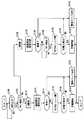
図1を参照して、本発明の実施の形態に係る充電システムが用いられるハイブリッド車について説明する。このハイブリッド車には、エンジン100と、MG(Motor Generator)200と、インバータ300と、コンバータ400と、バッテリパック500と、充電器600と、電源ECU1100と、HV_ECU1200と、充電ECU1300とが搭載される。なお、ECUの数は3つに限らない。また、電源ECU1100、HV_ECU1200および充電ECU1300を一つのECUに統合するようにしてもよい。 A hybrid vehicle using a charging system according to an embodiment of the present invention will be described with reference to FIG. In this hybrid vehicle,
ハイブリッド車は、エンジン100およびMG200の少なくともいずれか一方からの駆動力により走行する。ハイブリッド車の代わりに、MG200の駆動力のみにより走行する電気自動車、燃料電池車などを用いるようにしてもよい。 The hybrid vehicle travels by driving force from at least one of
MG200は、三相交流モータである。MG200は、バッテリパック500に蓄えられた電力により駆動する。MG200には、インバータ300により直流から交流に変換された電力が供給される。 MG200 is a three-phase AC motor. MG 200 is driven by the electric power stored in
MG200の駆動力は車輪に伝えられる。これにより、MG200はエンジン100をアシストしたり、MG200からの駆動力により車両を走行させたりする。一方、ハイブリッド車の回生制動時には、車輪によりMG200が駆動されることにより、MG200が発電機として作動される。これによりMG200は、制動エネルギを電力に変換する回生ブレーキとして作動する。MG200により発電された電力は、インバータ300により交流から直流に変換された後、バッテリパック500に蓄えられる。 The driving force of
バッテリパック500は、複数のバッテリセルを一体化したバッテリモジュールを、さらに複数直列に接続して構成された組電池である。バッテリパック500からの放電電圧およびバッテリパック500への充電電圧は、コンバータ400により調整される。 The
バッテリパック500の正極端子および負極端子には、充電器600が接続される。なお、バッテリの代わりに、キャパシタ(コンデンサ)を用いるようにしてもよい。 A
充電器600は、バッテリパック500に供給する電力の電圧および電流を制御する。充電器600からバッテリパック500には、直流電流が供給される。すなわち、充電器600は、交流電流を直流電流に変換する。また、充電器600は、電圧を昇圧する。 The
充電器600は、バッテリパック500を充電する際、ハイブリッド車の外部から、バッテリパック500およびに電力を供給する。なお、充電器600をハイブリッド車の外部に設置するようにしてもよい。 When charging
充電器600の内部には、電圧センサ602が設けられる。電圧センサ602により検出された電圧値を表わす信号は充電ECU1300に送信される。電圧センサ602により、バッテリパック500の直流電圧、もしくは外部の電源の交流電圧が検出される。なお、バッテリパック500の直流電圧を検出する電圧センサと、外部の電源の交流電圧を検出する電圧センサとを別々に設けるようにしてもよい。 A
充電器600は、インレット604に接続される充電ケーブルを介して、外部の電源と接続される。充電器600を介してバッテリパック500が外部の電源に接続される。 The
バッテリパック500と充電器600との間には、SMR(System Main Relay)502が設けられる。SMR502が開いた場合、バッテリパック500と充電器600とが遮断される。SMR502が閉じた場合、バッテリパック500と充電器600とが連結される。 An SMR (System Main Relay) 502 is provided between the
以下、電源ECU1100、HV_ECU1200および充電ECU1300について説明する。電源ECU1100、HV_ECU1200および充電ECU1300は、互いに通信が可能であるように設けられる。電源ECU1100、HV_ECU1200および充電ECU1300は、CPU(Central Processing Unit)、ROM(Read Only Memory)、RAM(Random Access Memory)などから構成されるコンピュータである。電源ECU1100、HV_ECU1200および充電ECU1300は、補機バッテリ(図示せず)から供給される電力により作動する。 Hereinafter,
電源ECU1100は、補機バッテリから電力が供給される間、常に起動している。HV_ECU1200は、起動した状態および停止した状態(電力の供給が遮断された状態)を切換えるように電源ECU1100により制御される。充電ECU1300の起動は、HV_ECU1200により制御される。 The
電源ECU1100は、IG信号をHV_ECU1200に送信することにより、HV_ECU1200が起動した状態および停止した状態を切換える。IG信号を用いてIG_ON指令が出力された場合、HV_ECU1200が起動する。IG信号を用いてIG_OFF指令が出力された場合、HV_ECU1200が停止する。 The
HV_ECU1200には、電圧センサ1010,1012、および電流センサ1020,1022から信号が入力される。 Signals are input to the
電圧センサ1010は、バッテリパック500の電圧値を検出する。電圧センサ1012は、システム電圧値(コンバータ400とインバータ300との間の区間における電圧値)を検出する。
電流センサ1020は、バッテリパック500から放電される電流値またはバッテリパック500に充電される電流値を検出する。電流センサ1022は、充電器600からバッテリパック500に供給される電流値を検出する。
HV_ECU1200は、これらのセンサから入力される電圧値および電流値などに基づいて、バッテリパック500の残存容量(SOC:State Of Charge)を算出する。なお、残存容量の算出方法は、周知の一般的な技術を利用すればよいため、ここではその詳細な説明は繰返さない。また、HV_ECU1200は、インバータ300、コンバータ400およびSMR502などを制御する。 The
充電ECU1300は、充電器600を制御する。充電器600には、電圧センサ602により検出された電圧値を表わす信号の他、電流センサ1024により検出された電流値を表わす信号が入力される。電流センサ1024は、充電ケーブル700を介してハイブリッド車の外部の電源から供給される電流値(交流電流値)を検出する。 Charging
図2を参照して、充電ケーブル700について説明する。充電ケーブル700は、コネクタ710と、プラグ720と、CCID(Charging Circuit Interrupt Device)730とを含む。充電ケーブル700は、EVSE(Electric Vehicle Supply Equipment)に相当する。 The charging
充電ケーブル700のコネクタ710は、ハイブリッド車に設けられたインレット604に接続される。コネクタ710には、スイッチ712が設けられる。充電ケーブル700のコネクタ710が、ハイブリッド車に設けられたインレット604に接続された状態でスイッチ712が閉じると、充電ケーブル700のコネクタ710が、ハイブリッド車に設けられたインレット604に接続された状態であることを表わすコネクタ信号CNCTが電源ECU1100およびHV_ECU1200に入力される。
本実施の形態においては、コネクタ信号CNCTが電源ECU1100およびHV_ECU1200に入力されると、電源ECU1100によりHV_ECU1200が起動され、その後、HV_ECU1200によりSMR502が閉じた状態になるように制御される。 In the present embodiment, when connector signal CNCT is input to
スイッチ712は、充電ケーブル700のコネクタ710をハイブリッド車のインレット604に係止する係止金具に連動して開閉する。係止金具は、コネクタ710に設けられたボタンを操作者が押すことにより揺動する。 The
たとえば、充電ケーブル700のコネクタ710がハイブリッド車に設けられたインレット604に接続した状態で、操作者が、図3に示すコネクタ710のボタン714から指を離した場合、係止金具716がハイブリッド車に設けられたインレット604に係合するとともに、スイッチ712が閉じる。操作者がボタン714を押すと、係止金具716とインレット604との係合が解除されるとともに、スイッチ712が開く。なお、スイッチ712を開閉する方法はこれに限らない。 For example, when the operator releases the finger from the
図2に戻って、充電ケーブル700のプラグ720は、家屋に設けられたコンセント802に接続される。コンセント802には、ハイブリッド車の外部の電源800から交流電力が供給される。 Returning to FIG. 2, the
CCID730は、リレー732およびコントロールパイロット回路734を有する。リレー732が開いた状態では、ハイブリッド車の外部の電源800からハイブリッド車へ電力を供給する経路が遮断される。リレー732が閉じた状態では、ハイブリッド車の外部の電源800からハイブリッド車へ電力を供給可能になる。リレー732の状態は、充電ケーブル700のコネクタ710がハイブリッド車のインレット604に接続された状態でHV_ECU1200により制御される。CCID730は、充電ケーブル700のプラグ720がコンセント802に接続されると起動する。CCID730は、ハイブリッド車の外部の電源800から供給される電力により作動する。 The
コントロールパイロット回路734は、充電ケーブル700のプラグ720がコンセント802、すなわち外部の電源800に接続され、かつコネクタ710がハイブリッド車に設けられたインレット604に接続された状態において、コントロールパイロット線にパイロット信号(方形波信号)CPLTを送る。 The
コントロールパイロット回路734は、充電ケーブル700のプラグ720がコンセント802に接続されると、コネクタ710がハイブリッド車に設けられたインレット604から外されていても、一定のパイロット信号CPLTを出力し得る。ただし、コネクタ710がハイブリッド車に設けられたインレット604から外された状態で出力されたパイロット信号CPLTを、HV_ECU1200は検出できない。 When the
充電ケーブル700のプラグ720がコンセント802に接続され、かつコネクタ710がハイブリッド車のインレット604に接続され、かつパイロット信号CPLTの電位が規定値に低下すると、コントロールパイロット回路734は、図4に示すように、予め定められたパルス幅(デューティサイクル)のパイロット信号CPLTを発振する。 When the
パイロット信号CPLTのパルス幅により、充電ケーブル700の電流容量(充電ケーブル700が供給可能な電流値)がハイブリッド車に通知される。パイロット信号CPLTのパルス幅は、外部の電源800の電圧および電流に依存せずに一定である。 The hybrid vehicle is notified of the current capacity of charging cable 700 (the current value that charging
一方、用いられる充電ケーブルの種類が異なれば、パイロット信号CPLTのパルス幅は異なり得る。すなわち、パイロット信号CPLTのパルス幅は、充電ケーブルの種類毎に定められ得る。 On the other hand, if the type of charging cable used is different, the pulse width of pilot signal CPLT may be different. That is, the pulse width of pilot signal CPLT can be determined for each type of charging cable.
図5を参照して、CCID730についてさらに説明する。CCID730は、リレー732およびコントロールパイロット回路734の他、電磁コイル736と、漏電検出器738とを含む。コントロールパイロット回路734は、発振器740と、抵抗素子742とを含む。 The
発振器740は、電源800から供給される電力によって作動する。発振器740は、抵抗素子742の出力電位が規定の電位V1(たとえば12V)近傍のときは非発振の信号を出力し、抵抗素子742の出力電位がV1から低下すると、予め定められた周波数(たとえば1kHz)およびデューティサイクルで発振する信号を出力する。すなわち、パイロット信号CPLTの電位がV1近傍のときは、コントロールパイロット回路734は、パイロット信号CPLTを発振させず、パイロット信号CPLTの電位がV1から低下すると、コントロールパイロット回路734は、予め定められた周波数およびデューティサイクルでパイロット信号CPLTを発振する。なお、パイロット信号CPLTの電位は、後述する抵抗回路900により抵抗値を切換えることによって操作される。 The
コントロールパイロット回路734は、パイロット信号CPLTの電位が規定の電位V3(たとえば6V)近傍のとき、電磁コイル736へ電流を供給する。電磁コイル736は、コントロールパイロット回路734から電流が供給されると電磁力を発生し、リレー732を閉じた状態にする。
漏電検出器738は、電源800からプラグインハイブリッド車へ充電電力を供給するための電力線対に設けられる。漏電検出器738は、漏電の有無を検出する。具体的には、漏電検出器738は、電力線対に互いに反対方向に流れる電流の平衡状態を検出し、その平衡状態が破綻すると漏電の発生を検出する。漏電検出器738により漏電が検出されると、電磁コイル736への給電が遮断され、リレー732がオフされる。
以下、抵抗回路900について説明する。抵抗回路900は、抵抗素子902,904と、リレー906と、接地ノード908とを含む。抵抗素子902は、パイロット信号CPLTの信号線と接地ノード908との間に接続される。抵抗素子904およびリレー906は、パイロット信号CPLTの信号線と接地ノード908との間に直列に接続され、抵抗素子902に並列に接続される。リレー906は、HV_ECU1200からの切換信号により制御される。 Hereinafter, the
抵抗回路900は、切換信号に応じてパイロット信号CPLTの電位を切換える。リレー906が開いた状態である場合には、抵抗素子902によってパイロット信号CPLTの電位が予め定められた電位V2(たとえば9V)に低下される。リレー906が閉じた状態である場合には、抵抗素子904によってパイロット信号CPLTの電位がさらに電位V3(たとえば6V)に低下される。
図6を参照して、HV_ECU1200の機能について説明する。なお、以下に説明する機能はハードウェアにより実現してもよく、ソフトウェアにより実現してもよい。 With reference to FIG. 6, the function of
HV_ECU1200は、第1作動部1201と、第2作動部1202とを備える。
第1作動部1201は、充電ケーブル700のプラグ720が電源800に接続されている状態で充電ケーブル700のコネクタ710が車両のインレット604に接続されると、HV_ECU1200と充電ECU1300との間で通信を確立し、さらに、充電器600が異常であるか否かを判定するように充電ECU1300に対して指令を出力する。すなわち、バッテリパック500を充電可能である状態になるように充電器600が起動される。The
When the
より具体的には、パイロット信号CPLTが発振している状態で、SMR502が開いた状態から閉じた状態に切換えられると、HV_ECU1200と充電ECU1300との間で通信が確立され、さらに、充電器600が異常であるか否かが判定される。 More specifically, when the
たとえば、電圧センサ602により検出される電圧がしきい値(たとえば0[V])以下であると、充電器600が異常であると判定される。なお、通信の確立および異常の判定のうちのいずれか一方を実行するようにしてもよい。 For example, when the voltage detected by
第2作動部1202は、充電ケーブル700のプラグ720が電源800に接続されてない状態で充電ケーブル700のコネクタ710が車両のインレット604に接続されると、充電ケーブル700のプラグ720が電源800に接続される前にHV_ECU1200と充電ECU1300との間で通信を確立し、さらに、充電器600が異常であるか否かを判定するように充電ECU1300に対して指令を出力する。 When the
より具体的には、パイロット信号CPLTが発振していない状態で、SMR502が開いた状態から閉じた状態に切換えられると、パイロット信号CPLTが発振される前にHV_ECU1200と充電ECU1300との間で通信が確立され、さらに、充電器600が異常であるか否かが判定される。 More specifically, when the pilot signal CPLT is not oscillating and the
図7を参照して、HV_ECU1200が実行するプログラムの制御構造について説明する。なお、以下に説明するプログラムは、たとえば車両の停車中に実行される。充電ECU1300により実行されるプログラムをCD(Compact Disc)、DVD(Digital Versatile Disc)、ROM(Read Only Memory)などの記録媒体に記録して市場に流通させてもよい。 A control structure of a program executed by
ステップ(以下、ステップをSと略す)100にて、HV_ECU1200は、コネクタ信号CNCTが車両に入力されているか否かを判定する。コネクタ信号が車両に入力されていると(S100にてYES)、処理はS102に移される。もしそうでないと(S100にてNO)、処理はS100に戻される。 In step (hereinafter, step is abbreviated as S) 100,
S102にて、HV_ECU1200は、充電ケーブル700のプラグ720が電源800に接続されているか否か、すなわちパイロット信号CPLTを検出したか否かを判定する。充電ケーブル700のプラグ720が電源800に接続されていると、すなわちパイロット信号CPLTが検出されると(S102にてYES)、処理はS110に移される。もしそうでないと(S102にてNO)、処理はS130に移される。 In S102,
S110にて、HV_ECU1200は、SMR502を閉じた状態にする。S112にて、HV_ECU1200は、HV_ECU1200との間で通信を確立し、さらに、充電器600が異常であるか否かを判定するように充電ECU1300に対して指令を出力する。 In S110,
S114にて、HV_ECU1200は、充電器600が異常であるか否かを判定する。充電器600が異常であると(S114にてYES)、処理はS122に移される。もしそうでないと(S114にてNO)、処理はS116に移される。 In S114,
S116にて、HV_ECU1200は、CCID730のリレー732を閉じた状態にする。S118にて、HV_ECU1200は、充電器600の電圧センサ602によりAC(交流)電圧が検出されたか否かを判定する。交流電圧が検出されると(S118にてYES)、処理はS120に移される。もしそうでないと(S118にてNO)、処理はS122に移される。 In S116,
S120にて、HV_ECU1200は、バッテリパック500の充電を開始する。S122にて、HV_ECU1200は、車両内に設けられた警告ランプ(図示せず)を点灯する。その後、この処理は終了する。 In S120,
S130にて、HV_ECU1200は、SMR502を閉じた状態にする。S132にて、HV_ECU1200は、HV_ECU1200との間で通信を確立し、さらに、充電器600が異常であるか否かを判定するように充電ECU1300に対して指令を出力する。 In S130,
S134にて、HV_ECU1200は、充電器600が異常であるか否かを判定する。充電器600が異常であると(S134にてYES)、処理はS144に移される。もしそうでないと(S134にてNO)、処理はS136に移される。 In S134,
S136にて、HV_ECU1200は、充電ケーブル700のプラグ720が電源800に接続されているか否か、すなわちパイロット信号CPLTを検出したか否かを判定する。充電ケーブル700のプラグ720が電源800に接続されていると(S136にてYES)、処理はS138に移される。もしそうでないと(S136にてNO)、処理はS136に戻される。 In S136,
S138にて、HV_ECU1200は、CCID730のリレー732を閉じた状態にする。S140にて、HV_ECU1200は、充電器600の電圧センサ602により交流電圧が検出されたか否かを判定する。交流電圧が検出されると(S140にてYES)、処理はS142に移される。もしそうでないと(S140にてNO)、処理はS144に移される。 In S138,
S142にて、HV_ECU1200は、バッテリパック500の充電を開始する。S144にて、HV_ECU1200は、車両内に設けられた警告ランプを点灯する。その後、この処理は終了する。 In S142,
以上のような構造およびフローチャートに基づく、本実施の形態に係る充電システムの作動について説明する。 The operation of the charging system according to the present embodiment based on the above-described structure and flowchart will be described.
[充電ケーブル700を電源800に接続した後に車両に接続する場合]
ユーザにより充電ケーブル700のプラグ720が電源800に接続された後、充電ケーブル700のコネクタ710が車両のインレット604に接続されると、図8の時間T1において示すように、コネクタ信号CNCTが車両に入力される(S100にてYES)。また、充電ケーブル700のプラグ720が電源800に接続されているため、充電ケーブル700のCCID730が起動する。[When charging
After the
この状態では、パイロット信号CPLTが検出される(S102にてYES)。したがって、時間T2において、SMR502が閉じた状態にされる(S110)。その後、時間T3において、HV_ECU1200と充電ECU1300との間で通信が確立され、さらに、充電器600が異常であるか否かを判定するように充電ECU1300に対して指令が出力される(S112)。これにより、充電器600が起動する。充電器600が起動すると、充電器600の状態を表わす充電器状態信号は、「待機」を示す。 In this state, pilot signal CPLT is detected (YES in S102). Therefore, at time T2, the
充電器600が正常であると(S114にてNO)、時間T4において、CCID730のリレー732が閉じた状態にされる(S116)。これにより、車両の外部の電源800から車両に対して電力を供給可能な状態になる。 If
充電器600の電圧センサ602により交流電圧が検出されると(S118にてYES)、正常に電力を供給可能である。よって、時間T5において、充電が開始される(S120)。充電が開始されると、充電器状態信号は、「充電開始」を示す。その後、時間T6において、充電器状態信号は、「充電中」を示す。 When AC voltage is detected by
充電器600が異常である場合(S114にてYES)、もしくは交流電圧が検出されなかった場合(S118にてNO)、ユーザに異常を報知するために、警告ランプが点灯される(S122)。 If
[充電ケーブル700を電源800に接続する前に車両に接続する場合]
充電ケーブル700のプラグ720が電源800に接続される前に、充電ケーブル700のコネクタ710が車両のインレット604に接続されると、図9の時間T11において、コネクタ信号CNCTが車両に入力される(S100にてYES)。なお、充電ケーブル700のプラグ720が電源800に接続されていないため、充電ケーブル700のCCID730は起動しない。[When charging
If the
この状態では、パイロット信号CPLTが検出されない(S102にてNO)。したがって、時間T12において、SMR502が閉じた状態にされる(S130)。その後、時間T13において、HV_ECU1200と充電ECU1300との間で通信が確立され、さらに、充電器600が異常であるか否かを判定するように充電ECU1300に対して指令が出力される(S130)。すなわち、充電ケーブル700のプラグ720が電源800に接続される前に、HV_ECU1200と充電ECU1300との間で通信が確立され、さらに、充電器600が異常であるか否かが判定される。 In this state, pilot signal CPLT is not detected (NO in S102). Therefore, at time T12, the
これにより、充電ケーブル700を介して車両と外部の電源800とが接続されていなくても、充電ケーブル700が車両に接続されると、HV_ECU1200と充電ECU1300との間で通信を確立し、さらに、充電器600が異常であるか否かを判定することができる。 Thereby, even if the vehicle and the
充電器600が正常であると(S134にてNO)、充電ケーブル700のプラグ720が電源800に接続されたか否か、すなわちパイロット信号CPLTを検出したか否かが判定される(S136)。 If
時間T14において、パイロット信号CPLTが検出されると(S136にてYES)、充電ケーブル700のCCID730が起動する。また、時間T15において、CCID730のリレー732が閉じた状態にされる(S138)。充電器600の電圧センサ602により交流電圧が検出されると(S140にてYES)、時間T16において、充電が開始される(S142)。 When pilot signal CPLT is detected at time T14 (YES in S136),
充電器600が異常である場合(S134にてYES)、もしくは交流電圧が検出されなかった場合(S140にてNO)、警告ランプが点灯される(S144)。 If
以上のように、本実施の形態に係る充電システムによれば、充電ケーブルのプラグが車両の外部の電源に接続されている状態で充電ケーブルのコネクタが車両のインレットに接続されると、充電器が異常であるか否かが判定される。充電ケーブルのプラグが車両の外部の電源に接続されていない状態で充電ケーブルのコネクタが車両のインレットに接続されると、充電ケーブルのプラグが車両の外部の電源に接続される前に充電器が異常であるか否かが判定される。これにより、充電ケーブルを介して車両と外部の電源とが接続されていなくても、充電ケーブルが車両に接続されると、充電器が異常であるか否かを判定することができる。そのため、たとえば、充電ケーブルの内部において断線がある場合であっても、充電ケーブルを修理もしくは交換する前に、充電器が異常であるか否かを判定することができる。その結果、充電器が異常であるか否かを速やかに判定することができる。 As described above, according to the charging system of the present embodiment, when the charging cable connector is connected to the vehicle inlet while the charging cable plug is connected to the power supply outside the vehicle, the charger Whether or not is abnormal is determined. If the charging cable connector is connected to the vehicle inlet when the charging cable plug is not connected to the external power supply of the vehicle, the charger will be connected before the charging cable plug is connected to the external power supply of the vehicle. It is determined whether or not there is an abnormality. Thereby, even if the vehicle and the external power source are not connected via the charging cable, it can be determined whether or not the charger is abnormal when the charging cable is connected to the vehicle. Therefore, for example, even when there is a disconnection inside the charging cable, it is possible to determine whether or not the charger is abnormal before repairing or replacing the charging cable. As a result, it is possible to quickly determine whether or not the charger is abnormal.
今回開示された実施の形態は、すべての点で例示であって制限的なものではないと考えられるべきである。本発明の範囲は上記した説明ではなくて特許請求の範囲によって示され、特許請求の範囲と均等の意味および範囲内でのすべての変更が含まれることが意図される。 The embodiment disclosed this time should be considered as illustrative in all points and not restrictive. The scope of the present invention is defined by the terms of the claims, rather than the description above, and is intended to include any modifications within the scope and meaning equivalent to the terms of the claims.
100 エンジン、200 MG、300 インバータ、400 コンバータ、500 バッテリパック、502 SMR、600 充電器、602 電圧センサ、604 インレット、700 充電ケーブル、710 コネクタ、712 スイッチ、714 ボタン、716 係止金具、720 プラグ、732 リレー、734 コントロールパイロット回路、736 電磁コイル、738 漏電検出器、740 発振器、742 抵抗素子、800 電源、802 コンセント、900 抵抗回路、902,904 抵抗素子、906 リレー、908 接地ノード、1010,1012 電圧センサ、1020,1022,1024 電流センサ、1100 電源ECU、1200 HV_ECU、1201 第1作動部、1202 第2作動部、1300 充電ECU。 100 engine, 200 MG, 300 inverter, 400 converter, 500 battery pack, 502 SMR, 600 charger, 602 voltage sensor, 604 inlet, 700 charging cable, 710 connector, 712 switch, 714 button, 716 locking bracket, 720 plug , 732 relay, 734 control pilot circuit, 736 electromagnetic coil, 738 leakage detector, 740 oscillator, 742 resistance element, 800 power supply, 802 outlet, 900 resistance circuit, 902, 904 resistance element, 906 relay, 908 ground node, 1010, 1012 Voltage sensor, 1020, 1022, 1024 Current sensor, 1100 Power supply ECU, 1200 HV_ECU, 1201 First operation unit, 1202 Second operation unit, 1300 Charge ECU.
Claims (4)
Translated fromJapanese前記連結器が前記電源に接続されている状態で前記連結器が前記車両に接続されると、予め定められた処理を実行するように作動するための第1の作動手段と、
前記連結器が前記電源に接続されていない状態で前記連結器が前記車両に接続されると、前記連結器が前記電源に接続される前に前記予め定められた処理を実行するように作動するための第2の作動手段とを備え、
前記予め定められた処理は、前記充電システムに異常があるか否かを判定するという処理である、充電システム。A charging system for charging a power storage mechanism mounted on a vehicle with electric power supplied from a power source external to the vehicle via a coupler,
First operating means for operating to execute a predetermined process when the coupler is connected to the vehicle in a state where the coupler is connected to the power source;
When the coupler is connected to the vehicle with the coupler not connected to the power source, the coupler operates to perform the predetermined process before being connected to the power source. and a second actuating meansfor,
The predetermined process is a charging system that determines whether or not there is an abnormality in the charging system.
前記蓄電機構および前記充電システムの間には、前記第2の信号が発生した場合に前記蓄電機構および前記充電システムを遮断した状態から連結した状態に切換える機構が設けられ、
前記第1の作動手段は、前記第1の信号が発生している状態で前記蓄電機構および前記充電システムを遮断した状態から連結した状態に切換えられた場合、前記予め定められた処理を実行するように作動するための手段を含み、
前記第2の作動手段は、前記第1の信号が発生していない状態で前記蓄電機構および前記充電システムを遮断した状態から連結した状態に切換えられた場合、前記第1の信号が発生する前に前記予め定められた処理を実行するように作動するための手段を含む、請求項1に記載の充電システム。The coupler includes a mechanism for generating a first signal when the coupler is connected to the vehicle and a power source external to the vehicle, and a second mechanism when the coupler is connected to the vehicle. And a mechanism for generating a signal,
A mechanism is provided between the power storage mechanism and the charging system to switch the power storage mechanism and the charging system from a disconnected state to a connected state when the second signal is generated,
The first actuating means executes the predetermined processing when the storage mechanism and the charging system are switched from a disconnected state to a connected state while the first signal is generated. Including means for operating to
When the second operating means is switched from a disconnected state to a connected state in a state where the first signal is not generated, before the first signal is generated. The charging system of claim 1, further comprising means for operating to perform the predetermined process.
前記連結器が前記電源に接続されている状態で前記連結器が前記車両に接続されると、予め定められた処理を実行するように作動するステップと、
前記連結器が前記電源に接続されていない状態で前記連結器が前記車両に接続されると、前記連結器が前記電源に接続される前に前記予め定められた処理を実行するように作動するステップとを備え、
前記予め定められた処理は、前記充電システムに異常があるか否かを判定するという処理である、充電システムの作動方法。An operation method of a charging system for charging a power storage mechanism mounted on a vehicle with electric power supplied from a power source external to the vehicle via a coupler,
When the coupler is connected to the vehicle in a state where the coupler is connected to the power source, and a step of performing a predetermined process;
When the coupler is connected to the vehicle with the coupler not connected to the power source, the coupler operates to perform the predetermined process before being connected to the power source. With steps,
The method of operatinga charging system,wherein the predetermined process is a process of determining whether or not there is an abnormality in the charging system.
前記蓄電機構および前記充電システムの間には、前記第2の信号が発生した場合に前記蓄電機構および前記充電システムを遮断した状態から連結した状態に切換える機構が設けられ、
前記連結器が前記電源に接続されている状態で前記連結器が前記車両に接続されると、前記予め定められた処理を実行するように作動するステップは、前記第1の信号が発生している状態で前記蓄電機構および前記充電システムを遮断した状態から連結した状態に切換えられた場合、前記予め定められた処理を実行するように作動するステップを含み、
前記連結器が前記電源に接続されていない状態で前記連結器が前記車両に接続されると、前記連結器が前記電源に接続される前に前記予め定められた処理を実行するように作動するステップは、前記第1の信号が発生していない状態で前記蓄電機構および前記充電システムを遮断した状態から連結した状態に切換えられた場合、前記第1の信号が発生する前に前記予め定められた処理を実行するように作動するステップを含む、請求項3に記載の充電システムの作動方法。The coupler includes a mechanism for generating a first signal when the coupler is connected to the vehicle and a power source external to the vehicle, and a second mechanism when the coupler is connected to the vehicle. And a mechanism for generating a signal,
A mechanism is provided between the power storage mechanism and the charging system to switch the power storage mechanism and the charging system from a disconnected state to a connected state when the second signal is generated,
When the coupler is connected to the vehicle in a state where the coupler is connected to the power source, the step of operating to execute the predetermined process is performed when the first signal is generated. When the storage mechanism and the charging system are switched from a disconnected state to a connected state in a state in which the power storage mechanism and the charging system are switched,
When the coupler is connected to the vehicle with the coupler not connected to the power source, the coupler operates to perform the predetermined process before being connected to the power source. The step is determined in advance before the first signal is generated when the storage mechanism and the charging system are switched from a disconnected state to a connected state in a state where the first signal is not generated. The method of operating a charging system according to claim3 , further comprising the step of operating to perform the process.
Priority Applications (9)
| Application Number | Priority Date | Filing Date | Title |
|---|---|---|---|
| JP2007309143AJP4254894B1 (en) | 2007-11-29 | 2007-11-29 | Charging system and operating method thereof |
| BRPI0819842-0ABRPI0819842B1 (en) | 2007-11-29 | 2008-09-02 | LOAD SYSTEM AND METHOD TO OPERATE THE SAME |
| AU2008330954AAU2008330954B2 (en) | 2007-11-29 | 2008-09-02 | Electric charging system and its operation method |
| RU2010126485/11ARU2438887C1 (en) | 2007-11-29 | 2008-09-02 | Charging system and method of control thereof |
| EP08853584.4AEP2218607B1 (en) | 2007-11-29 | 2008-09-02 | Electric charging system and its operation method |
| US12/682,861US8294415B2 (en) | 2007-11-29 | 2008-09-02 | Charging system and method for operating the same |
| CN2008801181806ACN101878131B (en) | 2007-11-29 | 2008-09-02 | Electric charging system and operation method thereof |
| PCT/JP2008/065714WO2009069357A1 (en) | 2007-11-29 | 2008-09-02 | Electric charging system and its operation method |
| KR1020107012786AKR101155537B1 (en) | 2007-11-29 | 2008-09-02 | Charging system and its operation method |
Applications Claiming Priority (1)
| Application Number | Priority Date | Filing Date | Title |
|---|---|---|---|
| JP2007309143AJP4254894B1 (en) | 2007-11-29 | 2007-11-29 | Charging system and operating method thereof |
Publications (2)
| Publication Number | Publication Date |
|---|---|
| JP4254894B1true JP4254894B1 (en) | 2009-04-15 |
| JP2009136073A JP2009136073A (en) | 2009-06-18 |
Family
ID=40612157
Family Applications (1)
| Application Number | Title | Priority Date | Filing Date |
|---|---|---|---|
| JP2007309143AActiveJP4254894B1 (en) | 2007-11-29 | 2007-11-29 | Charging system and operating method thereof |
Country Status (9)
| Country | Link |
|---|---|
| US (1) | US8294415B2 (en) |
| EP (1) | EP2218607B1 (en) |
| JP (1) | JP4254894B1 (en) |
| KR (1) | KR101155537B1 (en) |
| CN (1) | CN101878131B (en) |
| AU (1) | AU2008330954B2 (en) |
| BR (1) | BRPI0819842B1 (en) |
| RU (1) | RU2438887C1 (en) |
| WO (1) | WO2009069357A1 (en) |
Cited By (3)
| Publication number | Priority date | Publication date | Assignee | Title |
|---|---|---|---|---|
| WO2011074244A1 (en) | 2009-12-14 | 2011-06-23 | パナソニック株式会社 | Automobile charging apparatus |
| CN103260934A (en)* | 2010-10-21 | 2013-08-21 | 西门子公司 | Method and device for detecting a short-ircuit |
| CN110077271A (en)* | 2018-01-25 | 2019-08-02 | 保时捷股份公司 | Communication unit for vehicle |
Families Citing this family (41)
| Publication number | Priority date | Publication date | Assignee | Title |
|---|---|---|---|---|
| JP5566056B2 (en)* | 2009-07-15 | 2014-08-06 | 日東工業株式会社 | charging cable |
| JP2011050162A (en)* | 2009-08-26 | 2011-03-10 | Toyota Motor Corp | Vehicle |
| BRPI0924742B1 (en)* | 2009-12-21 | 2019-07-02 | Toyota Jidosha Kabushiki Kaisha | LOADING SYSTEM. |
| DE112010005299B4 (en)* | 2010-02-23 | 2015-11-26 | Toyota Jidosha Kabushiki Kaisha | Vehicle with a power switch whose normality is checked at startup |
| JP5475542B2 (en)* | 2010-05-12 | 2014-04-16 | 株式会社東海理化電機製作所 | Power supply plug lock structure for battery charging power receiving connector |
| US8841881B2 (en) | 2010-06-02 | 2014-09-23 | Bryan Marc Failing | Energy transfer with vehicles |
| US20110320056A1 (en)* | 2010-06-23 | 2011-12-29 | Leviton Manufacturing Co., Inc. | Electric vehicle supply equipment with metering and communicatons |
| KR101180956B1 (en)* | 2010-12-02 | 2012-09-07 | 기아자동차주식회사 | Antitheft system of charger for electric vehicle |
| DE102010055925A1 (en)* | 2010-12-23 | 2012-06-28 | Daimler Ag | Vehicle device |
| DE102011008700A1 (en)* | 2011-01-15 | 2012-07-19 | Volkswagen Ag | Method for charging traction battery used for e.g. driving electrical vehicle, involves connecting traction battery again with traction network after successful connection of charging device to charging interface is detected |
| EP2479879A1 (en) | 2011-01-19 | 2012-07-25 | Power Research Electronics B.v. | Resonat power converter |
| EP2479059A1 (en)* | 2011-01-19 | 2012-07-25 | Power Research Electronics B.v. | Battery charger for electric vehicles |
| US8712648B2 (en) | 2011-03-08 | 2014-04-29 | Gm Global Technology Operations | Passive charge cord release system for an electric vehicle |
| DE102011007042A1 (en)* | 2011-03-18 | 2012-09-20 | Elektro-Bauelemente Gmbh | Protection circuitry |
| PL2500208T5 (en) | 2011-03-18 | 2021-07-19 | Compleo Charging Solutions Gmbh | Protective circuit assembly |
| DE102011016537A1 (en) | 2011-04-08 | 2012-10-11 | Audi Ag | Charging device for a high-voltage battery of a motor vehicle, charging arrangement and method for operating a charging arrangement |
| US9399402B2 (en) | 2011-04-21 | 2016-07-26 | Lear Corporation | Proximity detection circuit for on-board vehicle charger |
| FR2974686B1 (en)* | 2011-04-27 | 2013-06-14 | Peugeot Citroen Automobiles Sa | SECURE LOAD SYSTEM OF AN ELECTRIC OR HYBRID VEHICLE |
| DE102011101191A1 (en)* | 2011-05-11 | 2012-11-15 | Volkswagen Aktiengesellschaft | Method for operating battery charger for supplying electric power to electromotor of e.g. electric car, involves decoupling charging device from power supply system if difference value between currents exceeds predetermined threshold value |
| US9211798B2 (en) | 2011-07-28 | 2015-12-15 | Lear Corporation | Multistage power supply system and method for providing uninterrupted power to vehicle circuitry |
| CN103097174B (en)* | 2011-08-25 | 2015-05-06 | 丰田自动车株式会社 | Vehicle, charging system, and method for controlling vehicle |
| DE102011111444A1 (en)* | 2011-08-30 | 2013-02-28 | Phoenix Contact Gmbh & Co. Kg | Control device for controlling a locking actuator |
| JP5835152B2 (en)* | 2011-09-16 | 2015-12-24 | 日立金属株式会社 | Vehicle charging device |
| US8749198B2 (en) | 2011-11-10 | 2014-06-10 | Lear Corporation | Control pilot detection circuit |
| US9233611B2 (en) | 2011-11-10 | 2016-01-12 | Lear Corporation | Proximity detection circuit having short protection |
| US9440538B2 (en) | 2011-11-11 | 2016-09-13 | Lear Corporation | Housekeeping circuit having trickle charge capabilities |
| JP2014072061A (en)* | 2012-09-28 | 2014-04-21 | Panasonic Corp | Electric connector for electric vehicle |
| CN103887760B (en)* | 2012-12-20 | 2017-11-03 | 通用电气公司 | Fault protection system and method |
| DE102013005072B3 (en) | 2013-03-22 | 2014-09-04 | Volkswagen Aktiengesellschaft | Method and device for checking a control pilot line |
| US9878628B2 (en)* | 2013-03-29 | 2018-01-30 | Nissan Motor Co., Ltd. | Power supply device, vehicle and non-contact power supply system |
| MY162431A (en)* | 2013-03-29 | 2017-06-15 | Nissan Motor | Non-contact power supply system |
| JP2014212653A (en)* | 2013-04-19 | 2014-11-13 | パナソニック株式会社 | Connection monitoring device, battery utilization system |
| CN105340153B (en)* | 2013-06-26 | 2019-01-22 | 日产自动车株式会社 | Charging device and contactless power supply device |
| DE102013212221A1 (en)* | 2013-06-26 | 2014-12-31 | Bayerische Motorenwerke Aktiengesellschaft | Charging port detection |
| JP6583610B2 (en)* | 2014-05-27 | 2019-10-02 | 三菱自動車工業株式会社 | Fault diagnosis device for vehicle charging system |
| US9804034B2 (en) | 2014-11-14 | 2017-10-31 | Schneider Electric USA, Inc. | EVSE with cordset handle temperature measurement |
| US9573478B2 (en) | 2014-11-14 | 2017-02-21 | Schneider Electric USA, Inc. | EVSE doubler add-on unit |
| US9707850B2 (en) | 2014-11-18 | 2017-07-18 | Schneider Electric USA, Inc. | EVSE handle with automatic thermal shut down by NTC to ground |
| KR101901798B1 (en) | 2016-07-01 | 2018-09-27 | 현대자동차주식회사 | Plug-in vehicle and method of controlling thereof |
| DE102016220513A1 (en)* | 2016-10-19 | 2018-04-19 | Borgward Trademark Holdings Gmbh | Charge control method and apparatus and charging system for an electric vehicle |
| CN113858986B (en)* | 2020-06-30 | 2023-06-13 | 比亚迪股份有限公司 | Charging switching device, vehicle and method for identifying charging and discharging modes of vehicle |
Family Cites Families (14)
| Publication number | Priority date | Publication date | Assignee | Title |
|---|---|---|---|---|
| JPH0595607A (en) | 1991-05-16 | 1993-04-16 | Honda Motor Co Ltd | Electric motor vehicle |
| US5202617A (en)* | 1991-10-15 | 1993-04-13 | Norvik Technologies Inc. | Charging station for electric vehicles |
| DE4213405C2 (en) | 1992-04-23 | 1996-05-30 | Lech Elektrizitaetswerke Ag | Petrol pump for a charging station |
| JPH062944U (en) | 1992-06-10 | 1994-01-14 | 三菱自動車工業株式会社 | Separate type charger |
| JPH06343202A (en)* | 1993-06-01 | 1994-12-13 | Nissan Motor Co Ltd | Electric vehicle charging device |
| RU2072605C1 (en)* | 1993-06-18 | 1997-01-27 | Инновационно-внедренческий центр "Менеджер-1" | Method for gradual fast charging of storage battery and device which implements said method |
| JPH07298502A (en)* | 1994-04-21 | 1995-11-10 | Daihatsu Motor Co Ltd | Battery charger |
| JPH0865904A (en)* | 1994-06-06 | 1996-03-08 | Nippondenso Co Ltd | Charger for electric automobile |
| JPH10304582A (en) | 1997-04-25 | 1998-11-13 | Toyota Motor Corp | Inductive charging equipment and inductive charging system |
| JP3715089B2 (en)* | 1997-09-15 | 2005-11-09 | 本田技研工業株式会社 | Battery charger |
| JP3915219B2 (en) | 1998-01-16 | 2007-05-16 | トヨタ自動車株式会社 | Electric vehicle charger |
| RU2222098C2 (en)* | 2002-04-09 | 2004-01-20 | Открытое акционерное общество "АВТОВАЗ" | Traction drive engineering package |
| JP5078119B2 (en)* | 2005-12-06 | 2012-11-21 | トヨタ自動車株式会社 | Charger |
| US7489048B2 (en)* | 2006-01-09 | 2009-02-10 | General Electric Company | Energy storage system for electric or hybrid vehicle |
- 2007
- 2007-11-29JPJP2007309143Apatent/JP4254894B1/enactiveActive
- 2008
- 2008-09-02KRKR1020107012786Apatent/KR101155537B1/enactiveActive
- 2008-09-02USUS12/682,861patent/US8294415B2/enactiveActive
- 2008-09-02BRBRPI0819842-0Apatent/BRPI0819842B1/enactiveIP Right Grant
- 2008-09-02CNCN2008801181806Apatent/CN101878131B/enactiveActive
- 2008-09-02WOPCT/JP2008/065714patent/WO2009069357A1/enactiveApplication Filing
- 2008-09-02AUAU2008330954Apatent/AU2008330954B2/enactiveActive
- 2008-09-02RURU2010126485/11Apatent/RU2438887C1/enactive
- 2008-09-02EPEP08853584.4Apatent/EP2218607B1/enactiveActive
Cited By (5)
| Publication number | Priority date | Publication date | Assignee | Title |
|---|---|---|---|---|
| WO2011074244A1 (en) | 2009-12-14 | 2011-06-23 | パナソニック株式会社 | Automobile charging apparatus |
| US9054550B2 (en) | 2009-12-14 | 2015-06-09 | Panasonic Intellectual Property Management Co., Ltd. | Automobile charging apparatus |
| CN103260934A (en)* | 2010-10-21 | 2013-08-21 | 西门子公司 | Method and device for detecting a short-ircuit |
| CN110077271A (en)* | 2018-01-25 | 2019-08-02 | 保时捷股份公司 | Communication unit for vehicle |
| CN110077271B (en)* | 2018-01-25 | 2022-05-31 | 保时捷股份公司 | communication unit for vehicle |
Also Published As
| Publication number | Publication date |
|---|---|
| KR20100082862A (en) | 2010-07-20 |
| KR101155537B1 (en) | 2012-06-19 |
| BRPI0819842B1 (en) | 2019-03-06 |
| BRPI0819842A2 (en) | 2015-06-16 |
| AU2008330954A1 (en) | 2009-06-04 |
| CN101878131A (en) | 2010-11-03 |
| RU2438887C1 (en) | 2012-01-10 |
| WO2009069357A1 (en) | 2009-06-04 |
| CN101878131B (en) | 2013-01-02 |
| EP2218607B1 (en) | 2017-10-25 |
| JP2009136073A (en) | 2009-06-18 |
| US20100225274A1 (en) | 2010-09-09 |
| EP2218607A1 (en) | 2010-08-18 |
| AU2008330954B2 (en) | 2014-04-03 |
| US8294415B2 (en) | 2012-10-23 |
| EP2218607A4 (en) | 2013-10-30 |
Similar Documents
| Publication | Publication Date | Title |
|---|---|---|
| JP4254894B1 (en) | Charging system and operating method thereof | |
| JP4254890B2 (en) | Vehicle control device | |
| JP5327328B2 (en) | Charge control device and vehicle | |
| EP3154150B1 (en) | Battery controller | |
| JP6454466B2 (en) | Charge control device | |
| JP4849171B2 (en) | Charge system abnormality determination device and abnormality determination method | |
| EP2767430A1 (en) | Charging control device for vehicle, and vehicle equippped with same | |
| US20140343776A1 (en) | Power supply system for vehicle | |
| WO2015104750A1 (en) | Hybrid vehicle with means for disconnection of a depleted auxiliary battery in order to allow for more rapid main battery charging | |
| JP2010035277A (en) | Charging/discharging system and electric vehicle | |
| JP2011160604A (en) | vehicle | |
| JP5605165B2 (en) | Vehicle charging system, vehicle charging device, vehicle charging method, program, medium | |
| JP2024114750A (en) | Vehicle control device, vehicle, power supply system, program, and power supply method | |
| JP5757262B2 (en) | Air conditioner and vehicle equipped with the same | |
| JP2011200071A (en) | Vehicle controller and vehicle equipped with the same | |
| JP5332629B2 (en) | Electric vehicle charging system | |
| JP2014131434A (en) | Vehicular control device | |
| JP2025000240A (en) | Control device for vehicle exterior charging device | |
| JP2021083177A (en) | Charging system | |
| JPWO2013054387A1 (en) | VEHICLE CHARGE CONTROL DEVICE AND VEHICLE HAVING THE SAME |
Legal Events
| Date | Code | Title | Description |
|---|---|---|---|
| TRDD | Decision of grant or rejection written | ||
| A01 | Written decision to grant a patent or to grant a registration (utility model) | Free format text:JAPANESE INTERMEDIATE CODE: A01 Effective date:20090106 | |
| A01 | Written decision to grant a patent or to grant a registration (utility model) | Free format text:JAPANESE INTERMEDIATE CODE: A01 | |
| A61 | First payment of annual fees (during grant procedure) | Free format text:JAPANESE INTERMEDIATE CODE: A61 Effective date:20090119 | |
| FPAY | Renewal fee payment (event date is renewal date of database) | Free format text:PAYMENT UNTIL: 20120206 Year of fee payment:3 | |
| R151 | Written notification of patent or utility model registration | Ref document number:4254894 Country of ref document:JP Free format text:JAPANESE INTERMEDIATE CODE: R151 | |
| FPAY | Renewal fee payment (event date is renewal date of database) | Free format text:PAYMENT UNTIL: 20120206 Year of fee payment:3 | |
| FPAY | Renewal fee payment (event date is renewal date of database) | Free format text:PAYMENT UNTIL: 20120206 Year of fee payment:3 | |
| FPAY | Renewal fee payment (event date is renewal date of database) | Free format text:PAYMENT UNTIL: 20130206 Year of fee payment:4 | |
| FPAY | Renewal fee payment (event date is renewal date of database) | Free format text:PAYMENT UNTIL: 20130206 Year of fee payment:4 | |
| FPAY | Renewal fee payment (event date is renewal date of database) | Free format text:PAYMENT UNTIL: 20140206 Year of fee payment:5 |