JP4254546B2 - Mass spectrometer - Google Patents
Mass spectrometerDownload PDFInfo
- Publication number
- JP4254546B2 JP4254546B2JP2004003643AJP2004003643AJP4254546B2JP 4254546 B2JP4254546 B2JP 4254546B2JP 2004003643 AJP2004003643 AJP 2004003643AJP 2004003643 AJP2004003643 AJP 2004003643AJP 4254546 B2JP4254546 B2JP 4254546B2
- Authority
- JP
- Japan
- Prior art keywords
- nozzle
- liquid sample
- gas
- mass spectrometer
- droplet
- Prior art date
- Legal status (The legal status is an assumption and is not a legal conclusion. Google has not performed a legal analysis and makes no representation as to the accuracy of the status listed.)
- Expired - Fee Related
Links
Images


Landscapes
- Other Investigation Or Analysis Of Materials By Electrical Means (AREA)
- Electron Tubes For Measurement (AREA)
Description
Translated fromJapanese本発明は、液体試料をイオン化して分析を行う、高い検出感度を有する質量分析装置に関する。このような高感度装置は、精密な分析が要求される、ゲノム創薬、薬物動態試験、医薬品の研究開発、環境中の微量成分分析等に使用される。 The present invention relates to a mass spectrometer having high detection sensitivity for performing analysis by ionizing a liquid sample. Such high-sensitivity devices are used for genome drug discovery, pharmacokinetic tests, pharmaceutical research and development, analysis of trace components in the environment, and the like that require precise analysis.
質量分析装置では、イオン化部において試料のイオン化を行い、イオン化された試料を質量分析部に取り込んだ後、四重極質量フィルタ等の質量分析器により質量数([質量]/[電荷数])に応じて各種イオンを分離・検出することにより試料の分析を行う。 In a mass spectrometer, a sample is ionized in an ionization unit, and after the ionized sample is taken into the mass analysis unit, the mass number ([mass] / [number of charges]) is obtained by a mass analyzer such as a quadrupole mass filter. The sample is analyzed by separating and detecting various ions according to the conditions.
液体クロマトグラフなどから得られた液体試料のイオン化を行う方法として、大気圧下のイオン化室内に該液体試料を静電噴霧する方法(エレクトロスプレーイオン化法(ESI法))や、大気圧下のイオン化室内に噴霧された液滴とコロナ放電で生じたキャリアガスイオンとを反応させて試料をイオン化する方法(大気圧化学イオン化法(APCI法))などがある。 As a method of ionizing a liquid sample obtained from a liquid chromatograph or the like, a method of electrostatically spraying the liquid sample in an ionization chamber under atmospheric pressure (electrospray ionization method (ESI method)) or ionization under atmospheric pressure There is a method of ionizing a sample by reacting droplets sprayed in a room with carrier gas ions generated by corona discharge (atmospheric pressure chemical ionization method (APCI method)).
ESI法では、液体試料の噴霧を行うノズルの先端部より大気圧下のイオン化室内に液体試料を噴霧して液滴を形成する際に、ノズルの先端部に設けた電極と、質量分析部の入口又はイオン化室の隔壁等の対向電極との間に高電圧を印加し、この電圧により試料液滴に偏った電荷を付与する。 In the ESI method, when forming a droplet by spraying a liquid sample into the ionization chamber under atmospheric pressure from the tip of the nozzle that sprays the liquid sample, the electrode provided at the tip of the nozzle and the mass spectrometer A high voltage is applied between the inlet or a counter electrode such as a partition wall of the ionization chamber, and a biased charge is applied to the sample droplet by this voltage.
この帯電液滴は、イオン化室の雰囲気ガスとの摩擦による剪断力と溶媒の蒸発によって微粒化され、質量分析部の入口オリフィスより、真空下にある質量分析部に取り込まれる。取り込まれた帯電液滴は、入口オリフィス直後の脱溶媒部により加熱され、溶媒が除去されることにより、ガス相の試料成分によるイオンが発生する。ここで、脱溶媒が不十分で、溶媒が試料に付加した状態では、質量分析器で試料成分の検出が行われないため、質量分析部に液滴が取り込まれるまでにこの液滴をできるだけ微粒化することが望ましい。 The charged droplets are atomized by shearing force due to friction with the atmospheric gas in the ionization chamber and evaporation of the solvent, and are taken into the mass analysis unit under vacuum from the inlet orifice of the mass analysis unit. The charged charged droplets are heated by the solvent removal unit immediately after the inlet orifice, and the solvent is removed, thereby generating ions due to the sample component in the gas phase. Here, when the solvent removal is insufficient and the solvent is added to the sample, the sample component is not detected by the mass analyzer. It is desirable to make it.
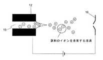
液滴を微粒化する方法の一つとして、二重管構造となったノズルから、窒素等のネブライズガスを噴出させつつ液体試料を噴霧して、試料液滴を形成する方法がある(特許文献1参照)。図1は、ESI法において用いられるノズル(エレクトロスプレー10)の一例(断面図)であって、このエレクトロスプレー10は、外側のネブライズガスガイド15と内側の噴霧キャピラリー11の二重管構造となっている。試料液滴の形成の際は、噴霧キャピラリー11に並行した流路(噴霧キャピラリー11とネブライズガスガイド15の間の流路)にネブライズガスが送給され、噴霧キャピラリー11の中心孔13の先端の液滴噴霧口14近傍にガスが噴出される。このように液滴の形成の際にネブライズガスを噴出させることにより、ネブライズガスの剪断力により生成した液滴が更に、高いガス圧力で前方へ押し出され、雰囲気ガスの抵抗を受けながらイオン化室内を飛行する。これにより、液滴の分裂が進むとともに、液滴からの溶媒の蒸発が促進され、微粒化した液滴が形成される。
噴霧キャピラリー11の先端部は金属電極12とされ、この電極12に、対向電極16に対して大きな電位差が与えられることにより、試料液滴は帯電することとなる(図2)。As one method for atomizing droplets, there is a method of forming a sample droplet by spraying a liquid sample while ejecting a nebulization gas such as nitrogen from a nozzle having a double tube structure (Patent Document 1). reference). FIG. 1 is an example (cross-sectional view) of a nozzle (electrospray 10) used in the ESI method. This
The tip of the
液滴を微粒化する別の方法として、エレクトロスプレーから液体試料を噴霧して試料液滴を形成し、噴霧された液滴群(ミスト)の方向と別方向から、加熱されたガスを噴出させ、ミストの流れと加熱されたガスとを交差させることにより、液滴を加熱する方法がある(特許文献2参照)。この方法では、ミストが、ミストの流れと別方向から噴出されたガスで加熱されることにより、液滴からの溶媒の蒸発が促進され、液滴が微粒化されることとなる。 As another method for atomizing droplets, a liquid sample is sprayed from an electrospray to form a sample droplet, and heated gas is ejected from a direction different from the direction of the sprayed droplet group (mist). There is a method of heating a droplet by crossing a mist flow and a heated gas (see Patent Document 2). In this method, the mist is heated by a gas ejected from a direction different from the mist flow, whereby the evaporation of the solvent from the droplet is promoted and the droplet is atomized.
特許文献1の方法を用いることにより、液滴を微粒化することは可能ではある。しかし、この方法では、電荷密度の高い微細な帯電液滴も形成されるが、それだけでなく、電荷密度の低いミクロンオーダーの大きな粒径を有する液滴も形成される。そのように大きな粒径を有する液滴は、質量が大きすぎて、電界や磁界などによりその運動を制御することが困難であって、このような液滴が質量分析装置の入口オリフィスから取り込まれた場合は、脱溶媒が不十分になり、質量分析部において質量分離されないまま検出部に到達し、ランダムノイズとして検出されることとなる。 また、そのような大きな粒径の液滴の取り込みにより、質量分析部の入口オリフィス近傍が冷却され、それにより、複数個の分子や原子が結合したクラスターが形成される場合がある。質量の大きなクラスターは、大きな粒径を有する液滴と同様、質量分析部において質量分離を行うことができない。
以上のことから、特許文献1の方法では、入口オリフィス直後に設けられた脱溶媒部において高い温度での加熱が必要であり、これ無しでは高い感度で試料の分析を行うことが困難である。By using the method of Patent Document 1, it is possible to atomize the droplets. However, in this method, fine charged droplets having a high charge density are formed, but not only that, but also droplets having a large particle size of micron order having a low charge density. A droplet having such a large particle size has a mass that is difficult to control its movement by an electric field or a magnetic field, and such a droplet is taken in from the inlet orifice of the mass spectrometer. In such a case, desolvation becomes insufficient, and the mass analysis unit reaches the detection unit without being separated by mass and is detected as random noise. In addition, by taking in droplets having such a large particle size, the vicinity of the inlet orifice of the mass analysis unit may be cooled, thereby forming a cluster in which a plurality of molecules and atoms are bonded. A cluster having a large mass cannot be subjected to mass separation in a mass analysis unit, like a droplet having a large particle size.
From the above, the method of Patent Document 1 requires heating at a high temperature in the solvent removal section provided immediately after the inlet orifice, and without this, it is difficult to analyze the sample with high sensitivity.
特許文献2の方法では、ミストの運動方向と加熱ガスの運動方向を交差させるが、加熱ガスとの交差により、ミストの運動方向が変化する。このため、加熱ガスの噴出速度等を考慮した上で、質量分析部の取り込み口から効率よく液滴の取り込みが行われるように液体試料の噴霧方向を予め設定しなければならないが、その方向の調整は困難である。
また、加熱ガスが液滴と交差する短時間の間に加熱を行って溶媒を蒸発させるため、加熱ガスの温度を数百度と非常に高温にする必要がある。そのため、タンパク質のような熱に弱い試料の場合には、この方法を適用するのは困難である。In the method of Patent Document 2, the movement direction of the mist and the movement direction of the heating gas are crossed. However, the movement direction of the mist changes due to the crossing with the heating gas. For this reason, it is necessary to set the spray direction of the liquid sample in advance so that the droplets can be efficiently taken in from the intake port of the mass analyzer in consideration of the ejection speed of the heated gas. Adjustment is difficult.
Further, since the solvent is evaporated by heating in a short time when the heated gas intersects with the droplets, the temperature of the heated gas needs to be as high as several hundred degrees. For this reason, it is difficult to apply this method in the case of a heat-sensitive sample such as a protein.
本発明はこのような課題を解決するために成されたものであり、その目的とするところは、液体試料をイオン化室に噴霧することにより形成される液滴の帯電効率を向上させるとともに、液滴を十分微粒化することにより、質量分析装置の検出感度を高めることにある。 The present invention has been made in order to solve such a problem. The object of the present invention is to improve the charging efficiency of droplets formed by spraying a liquid sample into an ionization chamber and The aim is to increase the detection sensitivity of the mass spectrometer by sufficiently atomizing the droplets.
上記課題を解決するために成された本発明に係る装置は、ノズル先端部に達した液体試料に電荷を付与しつつ、該液体試料を略大気圧下に噴霧することにより、該液体試料中の成分をイオン化するエレクトロスプレーを備える質量分析装置において、該エレクトロスプレーが、上記ノズル内に該液体試料を導入する手段と、該液体試料が該ノズル内をその壁面の略全周に沿って流れるように該ノズル内に噴霧ガスを送給する手段とを備えることを特徴とする。An apparatus according to the present invention, which has been made to solve the above problems, sprays the liquid sample under a substantially atmospheric pressure while applying an electric charge to the liquid sample reaching the tip of the nozzle. in the mass spectrometer equipped with electrospray ionizing component of the electrospray, means for introducingthe liquid sample into the nozzle, flowsthe liquid sample along the inside the nozzle to substantially the entire circumference of the wall And a means for feeding spray gas into the nozzle.
本発明に係る質量分析装置のエレクトロスプレーでは、ノズルの先端部より液体試料を噴霧する際は、ノズル内に液体試料を導入する手段、及び該ノズル内に噴霧ガスを送給する手段により、液体試料とともに噴霧ガスをノズル内に流し、液体試料が、ノズル内壁面の略全周に沿った状態で(中空円筒状に)ノズル先端部まで流れるようにする。
このような状態で液体試料がノズル内を流れるようにすることにより、ノズル先端部に設けられた電極の内壁と、液体試料の単位体積当たりの接触面積は大きくなり、液滴の帯電効率が向上する。また、少量の液体試料から液滴が形成されることとなるため、液滴は従来に比べて微粒化されやすい。In the electrospray of the mass spectrometer according to the present invention, when the liquid sample is sprayed from the tip of the nozzle, the liquid sample is introduced by means for introducing the liquid sample into the nozzle and by means for feeding the spray gas into the nozzle. A spray gas is allowed to flow into the nozzle together with the sample so that the liquid sample flows to the tip of the nozzle along a substantially entire circumference of the inner wall surface of the nozzle (in the form of a hollow cylinder).
By allowing the liquid sample to flow through the nozzle in such a state, the contact area per unit volume of the inner wall of the electrode provided at the nozzle tip and the liquid sample is increased, and the charging efficiency of the droplet is improved. To do. In addition, since the droplet is formed from a small amount of the liquid sample, the droplet is more easily atomized than the conventional one.
ここで、液体試料が該ノズル内壁面の略全周に沿って流れるようにするには、液体試料とともにノズルに流す噴霧ガスの流量は、液体試料の流量と比べて十分大きなもの、例えば10〜3000倍としなければならない。噴霧ガスの流量は、ノズルの内径、液体試料の溶媒の種類や表面張力、液体試料の流量等に応じて適宜設定する必要があるが、ノズルの内径が大きい場合や、液体試料の溶媒の表面張力や粘度が大きい場合、液体試料の流量が大きい場合等には、より大きな流量のガスを流す必要がある。
また、ノズル内を流れる液体試料の厚さを均一として、液滴の帯電が均一に行われるようにするために、噴霧ガスはノズルの略中心を流れるようにすることが望ましい。
なお、液体試料とともにノズルに流す噴霧ガスとしては、例えばほとんどの試料に対して不活性な窒素ガス、アルゴンガス、ヘリウムガスなどの不活性ガスや、酸素ガス、空気など、液体試料に対して不活性なものであれば、その種類は特に問わない。Here, in order to allow the liquid sample to flow along substantially the entire circumference of the inner wall surface of the nozzle, the flow rate of the spray gas flowing to the nozzle together with the liquid sample is sufficiently larger than the flow rate of the liquid sample, for example, 10 to Must be 3000 times. It is necessary to set the flow rate of the atomizing gas appropriately according to the inner diameter of the nozzle, the type and surface tension of the solvent of the liquid sample, the flow rate of the liquid sample, etc. When the tension or viscosity is large, or when the flow rate of the liquid sample is large, it is necessary to flow a gas with a larger flow rate.
Further, in order to make the thickness of the liquid sample flowing in the nozzle uniform and to charge the droplets uniformly, it is desirable that the atomizing gas flow in substantially the center of the nozzle.
The atomizing gas that flows to the nozzle together with the liquid sample is, for example, inert to liquid samples such as inert gas such as nitrogen gas, argon gas, and helium gas, oxygen gas, and air that are inert to most samples. The type is not particularly limited as long as it is active.
ここで、上記のノズルは、外管であるネブライズガスガイドと内管である噴霧キャピラリーから成る二重管構造とするのが望ましい。この場合、噴霧キャピラリー内に液体試料と噴霧ガスが送給され、噴霧キャピラリーとネブライズガスガイドの間の空間に窒素等のネブライズガスが送給される。液滴形成時に、液滴噴出口の周囲からネブライズガスを流すことにより、ネブライズガスを用いない場合に比べて、より微粒化された液滴を形成することができる。また、ネブライズガスを用いることにより、試料噴霧口に生成する液体試料の液塊がノズルの外壁面を逆行するのを防止することも可能となる。なお、ネブライズガスの流量は、ノズルの内径、液体試料の溶媒の種類や表面張力などを考慮して、液体試料の流量の10〜3000倍の範囲で適宜選択される。 Here, it is preferable that the nozzle has a double tube structure including a nebulized gas guide as an outer tube and a spray capillary as an inner tube. In this case, a liquid sample and a spray gas are fed into the spray capillary, and a nebulization gas such as nitrogen is fed into the space between the spray capillary and the nebulization gas guide. By flowing a nebulization gas from the periphery of the droplet ejection port when forming the droplet, it is possible to form a more atomized droplet as compared to the case where no nebulization gas is used. In addition, by using the nebulization gas, it is possible to prevent the liquid mass of the liquid sample generated at the sample spray port from reversing the outer wall surface of the nozzle. Note that the flow rate of the nebulizing gas is appropriately selected in the range of 10 to 3000 times the flow rate of the liquid sample in consideration of the inner diameter of the nozzle, the type of solvent of the liquid sample, the surface tension, and the like.
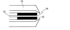
噴霧キャピラリーの先端部形状は、図3のように液滴噴霧口を頂点とするテーパ状とするのが望ましい。このような形状とすることにより、ネブライズガスの流れを液滴噴霧口方向に集めることが可能となり、先端部形状をテーパ状としない場合と比べて更に微粒化された液滴を形成することができる。 The shape of the tip of the spray capillary is preferably a taper shape with the droplet spray port as the apex as shown in FIG. By adopting such a shape, it becomes possible to collect the flow of the nebulizing gas in the direction of the droplet spraying port, and it is possible to form droplets that are further atomized compared to the case where the tip shape is not tapered. .
二重管構造とされた噴霧キャピラリーの先端部形状は従来通りの直角形状にして、ネブライズガスガイドの先端部形状を図4のように液滴噴霧口を頂点とするテーパ状としてもよい。このような構造とした場合も、ネブライズガスの流れを液滴噴霧口方向に集めることが可能であり、先端部形状をテーパ状としない場合と比べて更に微粒化された液滴を形成することができる。 The tip shape of the spray capillary having a double tube structure may be a conventional right-angled shape, and the tip shape of the nebulization gas guide may be tapered with the droplet spray port as the apex as shown in FIG. Even with such a structure, it is possible to collect the flow of the nebulizing gas in the direction of the droplet spraying port, and it is possible to form droplets that are further atomized as compared with the case where the tip shape is not tapered. it can.
なお、本発明に係る装置においては、内径が約0.1mm程度の通常のノズルを使用し、送液される液体試料の流量が0.1〜0.2mL/min程度である場合は、液体試料が鉛直上方向、下方向、水平等の任意の方向に送液されるようにエレクトロスプレーを設置することができる。しかし、生体試料の微量分析を行う場合のように、0.1mL/min以下と送液流量が少ない場合には、ノズルを流れる液体試料の厚さが薄くなり、表面張力の影響により液が塊になりやすくなる。このため、この場合は液体試料が鉛直上方向又は下方向に送液されるようにエレクトロスプレーを設置することが望ましい。これにより、ノズルの周方向のどのような位置においても液の厚さが略均一になり、試料の微細化及び帯電が均一に行われるようになる。 In the apparatus according to the present invention, when a normal nozzle having an inner diameter of about 0.1 mm is used and the flow rate of the liquid sample to be fed is about 0.1 to 0.2 mL / min, the liquid sample The electrospray can be installed so that the liquid is fed in an arbitrary direction such as a direction, a downward direction, and a horizontal direction. However, when the flow rate of liquid is low at 0.1 mL / min or less, as in the case of microanalysis of biological samples, the thickness of the liquid sample flowing through the nozzle becomes thin, and the liquid becomes a lump due to the effect of surface tension. It becomes easy to become. For this reason, in this case, it is desirable to install an electrospray so that the liquid sample is fed vertically upward or downward. As a result, the liquid thickness becomes substantially uniform at any position in the circumferential direction of the nozzle, and the sample is miniaturized and charged uniformly.
本発明に係る質量分析装置によれば、従来の装置に比べて試料液滴の帯電効率を向上させ、また、液滴を微粒化することが可能であるため、イオンの生成効率が向上し、従来に比べて高感度の質量分析を行うことができる。
また、試料液滴はイオン化室において十分微粒化されるため、質量分析部の入口オリフィス直後に設けられた脱溶媒部の温度を下げることが可能である。従って、本発明に係る装置は、タンパク質のような熱に不安定な試料の測定に好適に用いることができる。
試料液滴を更に微粒化する目的で、質量分析部の取り込み口から加熱ガスを噴出させるような場合にも、加熱ガスの温度を下げることが可能になると共に、従来よりも少ない加熱ガス流量で微粒化を行うことが可能になるため、装置のランニングコストを下げることも可能である。According to the mass spectrometer according to the present invention, the charging efficiency of the sample droplet can be improved as compared to the conventional apparatus, and the droplet can be atomized, so that the ion generation efficiency is improved. Highly sensitive mass spectrometry can be performed as compared with the prior art.
Further, since the sample droplet is sufficiently atomized in the ionization chamber, it is possible to lower the temperature of the desolvation unit provided immediately after the inlet orifice of the mass analysis unit. Therefore, the apparatus according to the present invention can be suitably used for measurement of a heat unstable sample such as protein.
The temperature of the heating gas can be lowered and the heating gas flow rate can be reduced compared to the conventional method even when the heating gas is ejected from the intake port of the mass spectrometer for the purpose of further atomizing the sample droplet. Since atomization can be performed, the running cost of the apparatus can be reduced.
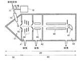
図5は、本発明を実施した四重極型質量分析装置の概略構成図である。質量分析装置20は、イオン化部30、質量分析部40、並びにこれら各部及びその構成要素の動作を制御する制御部(図示せず)等から成る。イオン化部30は、イオン化室31及びその中に備えられたエレクトロスプレー10等から成る。質量分析部40は、第1中間室41、第2中間室42、及び検出室43から成る。第1中間室41には第1イオンレンズ44が、第2中間室42には第2イオンレンズ45が、そして、検出室43には四重極フィルタ46と検出器47が備えられる。イオン化室31内の圧力は略大気圧とされ、第1中間室41、第2中間室42の順に室内の真空度が高められ、検出室43内は高真空状態とされる。 FIG. 5 is a schematic configuration diagram of a quadrupole mass spectrometer embodying the present invention. The
イオン化室31では、液体クロマトグラフ等から供給される液体試料が、エレクトロスプレー10から噴霧されることでイオン化される。このイオンは圧力差により対向電極である入口オリフィス(兼脱溶媒部)16から第1中間室41に吸引され、第1イオンレンズ44により収束・加速された後、同様に圧力差により第2中間室42に吸引される。ここでも同様に、試料イオンは第2イオンレンズ45により収束され、検出室43に送られる。検出室43では、四重極フィルタ46の各ロッドに印加されたRF電圧及び直流電圧により、所定の質量数のイオンのみが四重極フィルタ46の通過を許され、検出器47により検出される。 In the
試料溶液の噴霧が行われる際は、エレクトロスプレー10では、液体クロマトグラフ等から供給される液体試料が、ノズル内に液体試料を導入する手段としての液体試料導入管17を経て、ノズル内に噴霧ガスを送給する手段としてのガス供給装置18から送給された乾燥窒素ガス等とともに、噴霧キャピラリー11に送られる。試料溶液における溶媒には、例えば液体クロマトグラフ等で汎用される水/アセトニトリル混合液や水/エタノール混合液などが使用されるが、こうした溶媒の種類や粘度、表面張力、ノズル径などを考慮して、噴霧ガスの流量は、例えば、液体試料の流量の10〜3000倍と十分大きくなるように設定する。乾燥窒素ガス等とともに噴霧キャピラリー11に送られた液体試料は、ノズル内壁面の略全周に沿った中空円筒状で液滴噴霧口14まで流れることとなる。 When the sample solution is sprayed, in the
このような状態でノズル内を流れる液体試料は、噴霧キャピラリー11の先端部に設けられた電極12の内壁と、液体試料の単位体積当たりの接触面積が大きくなるため、形成される液滴の帯電効率が向上する。
また、噴霧キャピラリー11の先端部形状が液滴噴霧口14を頂点とするテーパ状とされた場合や、ネブライズガスガイドの先端部形状が、液滴噴霧口14を頂点とするテーパ状とされた場合には、ネブライズガスの流れが液滴噴霧口14の方向に集められるため、形成される液滴は十分に微粒化される。
以上のように液体試料の噴霧を行うことにより、試料のイオン化が促進され、従来の質量分析装置に比べて高感度の分析を行うことができるようになる。Since the liquid sample flowing in the nozzle in such a state has a large contact area per unit volume of the liquid sample with the inner wall of the
The tip shape of the
By spraying the liquid sample as described above, ionization of the sample is promoted, and analysis with higher sensitivity can be performed as compared with the conventional mass spectrometer.
10…エレクトロスプレー
11…噴霧キャピラリー
12…電極
13…中心孔
14…液滴噴霧口
15…ネブライズガスガイド
16…対向電極(入口オリフィス兼脱溶媒部)
17…液体試料導入管
18…ガス供給装置
20…質量分析装置
30…イオン化部
31…イオン化室
40…質量分析部
41…第1中間室
42…第2中間室
43…検出室
44…第1イオンレンズ
45…第2イオンレンズ
46…四重極フィルタ
47…検出器DESCRIPTION OF
17 ... Liquid
Claims (6)
Translated fromJapanesePriority Applications (1)
| Application Number | Priority Date | Filing Date | Title |
|---|---|---|---|
| JP2004003643AJP4254546B2 (en) | 2004-01-09 | 2004-01-09 | Mass spectrometer |
Applications Claiming Priority (1)
| Application Number | Priority Date | Filing Date | Title |
|---|---|---|---|
| JP2004003643AJP4254546B2 (en) | 2004-01-09 | 2004-01-09 | Mass spectrometer |
Publications (2)
| Publication Number | Publication Date |
|---|---|
| JP2005197141A JP2005197141A (en) | 2005-07-21 |
| JP4254546B2true JP4254546B2 (en) | 2009-04-15 |
Family
ID=34818481
Family Applications (1)
| Application Number | Title | Priority Date | Filing Date |
|---|---|---|---|
| JP2004003643AExpired - Fee RelatedJP4254546B2 (en) | 2004-01-09 | 2004-01-09 | Mass spectrometer |
Country Status (1)
| Country | Link |
|---|---|
| JP (1) | JP4254546B2 (en) |
Cited By (1)
| Publication number | Priority date | Publication date | Assignee | Title |
|---|---|---|---|---|
| CN108291892A (en)* | 2015-12-04 | 2018-07-17 | 株式会社岛津制作所 | Liquid sample analytic system |
Families Citing this family (8)
| Publication number | Priority date | Publication date | Assignee | Title |
|---|---|---|---|---|
| CN101113970B (en)* | 2007-08-28 | 2010-06-09 | 清华大学 | A mass spectrometry ion source without external high pressure and its ionization analysis method |
| JP2011513738A (en)* | 2008-03-07 | 2011-04-28 | ザ ユニバーシティー オブ ブリティッシュ コロンビア | Self-contained capillary electrophoresis system connected to mass spectrometry |
| CN101981549A (en) | 2008-03-27 | 2011-02-23 | 松下电器产业株式会社 | access control device |
| WO2013032835A1 (en)* | 2011-08-26 | 2013-03-07 | Waters Technologies Corporation | Reusable fitting for attaching a conduit to a port |
| CN105719939B (en)* | 2016-04-11 | 2017-11-17 | 清华大学深圳研究生院 | A kind of ultrasonic atomizatio ionization device |
| US11482405B2 (en)* | 2018-04-05 | 2022-10-25 | Shimadzu Corporation | Mass spectrometry device and mass spectrometry method |
| WO2020241098A1 (en)* | 2019-05-24 | 2020-12-03 | 国立研究開発法人産業技術総合研究所 | Spray ionization device, analysis device, and surface coating device |
| JP7433477B2 (en)* | 2020-12-16 | 2024-02-19 | 株式会社日立ハイテク | Ion source and mass spectrometer equipped with it |
- 2004
- 2004-01-09JPJP2004003643Apatent/JP4254546B2/ennot_activeExpired - Fee Related
Cited By (1)
| Publication number | Priority date | Publication date | Assignee | Title |
|---|---|---|---|---|
| CN108291892A (en)* | 2015-12-04 | 2018-07-17 | 株式会社岛津制作所 | Liquid sample analytic system |
Also Published As
| Publication number | Publication date |
|---|---|
| JP2005197141A (en) | 2005-07-21 |
Similar Documents
| Publication | Publication Date | Title |
|---|---|---|
| US7960711B1 (en) | Field-free electrospray nebulizer | |
| JP4178110B2 (en) | Mass spectrometer | |
| US10281433B2 (en) | Mass spectrometer and ion mobility spectrometer | |
| JP5589750B2 (en) | Ionizer for mass spectrometer and mass spectrometer equipped with the ionizer | |
| US20150048255A1 (en) | Ion Source for Mass Spectrometer and Method of Producing Analyte Ion Stream | |
| KR102483035B1 (en) | Multi-Gas Flow Ionizer | |
| JPH042033A (en) | Equipment for sample ionization and mass spectrometry | |
| US10020177B2 (en) | Piezo-electric vibration on an in-source surface ionization structure to aid secondary droplet reduction | |
| JP2000513873A (en) | Ion source for mass spectrometer and method of providing an ion source for analysis | |
| GB2441601A (en) | Ionizing apparatus | |
| US6646255B2 (en) | Liquid chromatograph/mass spectrometer and its ionization interface | |
| JP4254546B2 (en) | Mass spectrometer | |
| RU2530783C2 (en) | Apparatus for electrospraying chromatographic streams of test solutions of substances for ion sources | |
| US20030062474A1 (en) | Electrospray ion source for mass spectrometry with atmospheric pressure desolvating capabilities | |
| US8368012B2 (en) | Guiding charged droplets and ions in an electrospray ion source | |
| JP2011113832A (en) | Mass spectrometer | |
| JP2002015697A (en) | Electrospray ion source | |
| JP2002190272A (en) | Electrospray ion source | |
| JP2854761B2 (en) | ESI mass spectrometer | |
| JP2005026159A (en) | Mass spectrometer | |
| JP4839276B2 (en) | Liquid chromatograph mass spectrometer | |
| JP2012058122A (en) | Liquid chromatograph mass spectrometer | |
| RU2608362C2 (en) | Device of stable electro-spraying solutions of substances at atmospheric pressure for ion sources | |
| JP4389515B2 (en) | Mass spectrometer | |
| EP4266040A1 (en) | Ion source and mass spectrometer equipped therewith |
Legal Events
| Date | Code | Title | Description |
|---|---|---|---|
| A621 | Written request for application examination | Free format text:JAPANESE INTERMEDIATE CODE: A621 Effective date:20060411 | |
| A977 | Report on retrieval | Free format text:JAPANESE INTERMEDIATE CODE: A971007 Effective date:20070913 | |
| A131 | Notification of reasons for refusal | Free format text:JAPANESE INTERMEDIATE CODE: A131 Effective date:20080311 | |
| A131 | Notification of reasons for refusal | Free format text:JAPANESE INTERMEDIATE CODE: A131 Effective date:20080909 | |
| A521 | Written amendment | Free format text:JAPANESE INTERMEDIATE CODE: A523 Effective date:20081105 | |
| TRDD | Decision of grant or rejection written | ||
| A01 | Written decision to grant a patent or to grant a registration (utility model) | Free format text:JAPANESE INTERMEDIATE CODE: A01 Effective date:20090106 | |
| A01 | Written decision to grant a patent or to grant a registration (utility model) | Free format text:JAPANESE INTERMEDIATE CODE: A01 | |
| A61 | First payment of annual fees (during grant procedure) | Free format text:JAPANESE INTERMEDIATE CODE: A61 Effective date:20090119 | |
| FPAY | Renewal fee payment (event date is renewal date of database) | Free format text:PAYMENT UNTIL: 20120206 Year of fee payment:3 | |
| R150 | Certificate of patent or registration of utility model | Ref document number:4254546 Country of ref document:JP Free format text:JAPANESE INTERMEDIATE CODE: R150 Free format text:JAPANESE INTERMEDIATE CODE: R150 | |
| FPAY | Renewal fee payment (event date is renewal date of database) | Free format text:PAYMENT UNTIL: 20120206 Year of fee payment:3 | |
| FPAY | Renewal fee payment (event date is renewal date of database) | Free format text:PAYMENT UNTIL: 20130206 Year of fee payment:4 | |
| FPAY | Renewal fee payment (event date is renewal date of database) | Free format text:PAYMENT UNTIL: 20140206 Year of fee payment:5 | |
| LAPS | Cancellation because of no payment of annual fees |