JP4252877B2 - Motorcycle speaker mounting structure - Google Patents
Motorcycle speaker mounting structureDownload PDFInfo
- Publication number
- JP4252877B2 JP4252877B2JP2003353813AJP2003353813AJP4252877B2JP 4252877 B2JP4252877 B2JP 4252877B2JP 2003353813 AJP2003353813 AJP 2003353813AJP 2003353813 AJP2003353813 AJP 2003353813AJP 4252877 B2JP4252877 B2JP 4252877B2
- Authority
- JP
- Japan
- Prior art keywords
- speaker
- rider
- right direction
- vehicle body
- motorcycle
- Prior art date
- Legal status (The legal status is an assumption and is not a legal conclusion. Google has not performed a legal analysis and makes no representation as to the accuracy of the status listed.)
- Expired - Fee Related
Links
- 230000000694effectsEffects0.000description8
- 125000002066L-histidyl groupChemical group[H]N1C([H])=NC(C([H])([H])[C@](C(=O)[*])([H])N([H])[H])=C1[H]0.000description1
- 230000003247decreasing effectEffects0.000description1
- 238000009792diffusion processMethods0.000description1
- 230000002708enhancing effectEffects0.000description1
Images


Landscapes
- Steering Devices For Bicycles And Motorcycles (AREA)
- Fittings On The Vehicle Exterior For Carrying Loads, And Devices For Holding Or Mounting Articles (AREA)
Description
Translated fromJapanese本発明は、スクータなどの自動二輪車に設けられるオーディオシステムのスピーカの取付に特徴をもつ、自動二輪車のスピーカ取付構造に関するものである。 The present invention relates to a speaker mounting structure for a motorcycle characterized by mounting a speaker of an audio system provided in a motorcycle such as a scooter.
自動二輪車において、車体の前部のインストルメントパネルに、オーディオシステムのスピーカを取り付けたものは公知である(例えば、特許文献1参照)。
一般に、自動二輪車に装備されるオーディオシステムは、そのスピーカから発する音声に迫力ある立体感、すなわちステレオ効果を高めてライダーに聴取させ、しかも音声にライダーへの指向性をもたせて、それが車体の左右方向へ拡散するのを低減して、ライダーが交通情報などの外部情報を聞き取り易くし、その上、ライダーの前、後視界を妨げないようにすることが要求されるが、前記文献1に開示されるものでは、ライダー前方のインストルメントパネルに単に一対のスピーカを設けただけなので、前記要求に対する配慮がなされておらず、迫力あるステレオ効果を楽しみたいライダーにとって満足のいくものではなかった。 In general, an audio system installed in a motorcycle has a powerful three-dimensional effect on the sound emitted from its speakers, i.e., the stereo effect is enhanced so that the rider can listen to the sound, and the sound is given directivity to the rider. Although it is required to reduce diffusion in the left-right direction so that the rider can easily hear external information such as traffic information, and in addition, it is required not to disturb the front and rear views of the rider. In the disclosed one, since a pair of speakers are simply provided on the instrument panel in front of the rider, the above requirement is not taken into consideration, and it is not satisfactory for riders who want to enjoy a powerful stereo effect.
本発明は、かかる事情に鑑みてなされたもので、前記要求を充足できるようにした、新規な自動二輪車のスピーカ取付構造を提供することを目的とするものである。 The present invention has been made in view of such circumstances, and an object of the present invention is to provide a novel motorcycle speaker mounting structure capable of satisfying the above requirements.
上記目的を達成するために、請求項1に係る本発明は、オーディオシステム用スピーカの自動二輪車への取付構造であって、
車体前部に、左右方向に細長いスピーカー収納部を備えた、一本のスピーカーハウジングを設け、このスピーカーハウジングのスピーカー収納部内に、左右一対の前部スピーカーを、車体の左右方向に直列して収容し、そのスピーカーハウジングの、シート上に着座するライダーに対面する後側には、左右方向に長い開口部を設け、この開口部に、前記左右一対の前部スピーカーの発声部を対向させ、その発声部を開口部を介してライダーに向けて指向させたことを特徴としている。In order to achieve the above object, the present invention according to
A single speaker housing is provided at the front of the vehicle body with a speaker housing that is elongated in the left-right direction. A pair of left and right front speakers are housed in series in the left-right direction of the vehicle body in the speaker housing of the speaker housing. In the rear side of the speaker housing facing the rider seated on the seat, a long opening is provided in the left-right direction, and the utterances of the pair of left and right front speakers are opposed to the opening. The utterance part is directed toward the rider through the opening .
上記目的を達成するために、請求項2に係る本発明は、オーディオシステム用スピーカの自動二輪車への取付構造であって、
ライダーの着座するシートよりも前方で、車体前部の左右方向の中央部に、左右方向に細長い筒形状の一本のスピーカーハウジングを設け、このスピーカーハウジング内に左右に細長い筒形状のスピーカー収納部を設け、このスピーカー収納部内に、左右一対の前部スピーカーを車体の左右方向に直列して収容し、これらのスピーカーの発声部をスピーカーハウジングの後側に対向させ、スピーカーハウジングの後側に左右方向に長い開口部を設けて、前部スピーカーの発声部を、開口部を通してシート上に着座するライダーに指向させ、前記スピーカーハウジングはスピーカー収納部よりも下方に延びる取付部を介して車体に取り付けられていることを特徴としている。In order to achieve the above object, the present invention according to
In front of the seat on which the rider sits, a single speaker housing that is elongated in the left-right direction is provided at the center in the left-right direction at the front of the vehicle body. A pair of left and right front speakers are accommodated in series in the left-right direction of the vehicle body in the speaker housing, and the utterance part of these speakers is opposed to the rear side of the speaker housing, and the left and right sides of the speaker housing are A long opening in the direction is provided so that the utterance part of the front speaker is directed to the rider seated on the seat through the opening, and the speaker housing is attached to the vehicle body via an attachment part that extends downward from the speaker housing part. It is characterized by being.
上記目的を達成するために、請求項3に係る本発明は、オーディオシステム用スピーカの自動二輪車への取付構造であって、In order to achieve the above object, the present invention according to
ライダーの着座するシートよりも前方で、車体前部に操向可能に支持した操向ハンドルに、左右方向に細長い一本のクロスバーを設け、このクロスバー内に左右に細長いスピーカー収納部を設け、このスピーカー収納部内に、左右一対の、棒状の前部スピーカーを車体の左右方向に直列して収容し、これらのスピーカーの発声部をクロスバーの後側に対向させ、クロスバーの後側に左右方向に長い開口部を設けて、前部スピーカーの発声部を、開口部を通してシート上に着座するライダーに指向させたことを特徴としている。A steering handle that is slidably supported at the front of the vehicle body in front of the seat on which the rider sits is provided with a single crossbar that is elongated in the left-right direction. In this speaker housing, a pair of left and right rod-shaped front speakers are housed in series in the left-right direction of the vehicle body, and the utterance parts of these speakers are opposed to the rear side of the crossbar, A long opening is provided in the left-right direction, and the utterance part of the front speaker is directed to the rider seated on the seat through the opening.
上記請求項各項に係る本発明によれば、左右一対の前部スピーカからライダーに向けて音声が発せられるので、ライダーは、迫力のある立体的なサウンドを聴取してステレオ効果を楽しむことができる。特に、左右一対の前部スピーカの各発声部は、ライダーに指向されているので、それらから発するサウンドは、障害物に妨げられることなく、ライダーの前部に集中的に発せられてステレオ効果を一層高めることができる。また、サウンドがライダーの周囲に拡がるのを極力抑えることができ、ライダーは走行時の交通情報などの外部情報をキャッチしにくくなることがない。さらに、前記左右前部スピーカは、ライダーの前方および後方の視界を妨げることがない。According to the present invention according to the above claims, since sound is emitted from the pair of left and right front speakers toward the rider, the rider can enjoy a stereo effect by listening to powerful three-dimensional sound. it can. In particular, since each utterance part of the pair of left and right front speakers is directed to the rider, the sound emitted from them is intensively emitted to the front part of the rider without being obstructed by obstacles, and produces a stereo effect. It can be further enhanced. In addition, it is possible to suppress the sound from spreading around the rider as much as possible, and the rider does not become difficult to catch external information such as traffic information during driving. Further, the left and right front speakers do not interfere with the rider's front and rear views.
[第1実施例]
以下、本発明の第1実施例を、図1〜6に基づいて説明する。[First embodiment]
Hereinafter, a first embodiment of the present invention will be described with reference to FIGS.
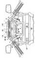
図1〜図6は本発明によるステアリングダンパ装置の第1実施例を示すもので、図1は、本発明スピーカ取付構造を備えたスクータの全体側面図、図2は、図1の2矢視のスクータ前面上部の拡大図、図3は、図1の3矢視のスクータのインストルメントパネル部分の拡大図、図4は、図3の4−4線に沿う拡大断面図、図5は、図1の5矢視のスクータのバックレスト部分の拡大図、図6は、図5の6−6線に沿う拡大断面図である。 1 to 6 show a first embodiment of a steering damper device according to the present invention. FIG. 1 is an overall side view of a scooter having a speaker mounting structure according to the present invention, and FIG. FIG. 3 is an enlarged view of the instrument panel portion of the scooter as viewed in the direction of
図1において、スクータの車体前部には、前輪WFが懸架されると共にこの前輪WFを操舵するための操向ハンドル1が左右に操向可能に設けられ、また、車体の後部には、図示しないエンジンによって駆動される後輪WRが懸架される。車体前部は前部カウリングCFにより覆われ、また車体後部は後部カウリングCRにより覆われる。前部カウリングCFの上縁には、上方に向けて起立するスクリーンSCが固定されている。前、後輪WF、WR間の車体上には、ライダーRの着座するライダー用シートTSが設けられ、さらに、このライダー用シートTSの前方には、ライダーRが足を乗せる平坦なステップSTが設けられる。また、車体の後部には、トランクTRが設けられ、このトランクTRの後面には、トランクリッドRIにより開閉される出入口が開口されている。そして、このトランクTR内には、オーディオシステムのCDプレーヤー、MDプレーヤー、DVD、MP3などのオーディオプレーヤーAPが収納される。 In FIG. 1, a front wheel WF is suspended at the front of the vehicle body of the scooter and a
前部カウリングCFには、操向ハンドル1の直前に配置されるインストルメントパネル2が一体に形成されており、このインストルメントパネル2には、その前縁から上方に向けて起立するバイザ3ーが設けられると共にこのバイザ3ーの内側にデジタルスピードメータ、デジタルタコメータなどのメータ類5が設置される。また、操向ハンドル1の中央部にナビゲーション用モニタ4が装着されている。 The front cowling CF is integrally formed with an
前記バイザ3ーの上部には、左右一対の前部スピーカ10L,10Rが着脱可能に取り付けられ、これらの前部スピーカ10L,10Rは、ハーネス36により後述するバックレスト受け23内に設けたアンプ26に接続される(図1参照)。 A pair of left and
以下、その取付構造について具体的に説明する。 Hereinafter, the mounting structure will be specifically described.
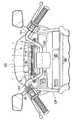
図4に明瞭に示すように、前部スピーカ10L,10Rのスピーカハウジング12は、前半部12fと後半部12rとを有して前後に分割可能で、それらをビス13止めして構成されている。このスピーカハウジング12は左右に細長い円筒状のスピーカ収容部14を備え、このスピーカ収容部14より下方に延びる前部及び下部取付部が、バイザ3ーの上部を跨いでその前後にビス止め15,16され、これにより、スピーカハウジング12は、バイザ3ーの上部に、スピーカ収容部14を左右方向に向けて着脱可能に取り付けられる。左右方向に長いスピーカ収容部14内には、円筒状に形成される左右一対の前部スピーカ10L,10Rが車体の左右方向に直列して収容される。図3,4に示すように、左右一対の前部スピーカ10L,10Rの発声部に対応して、スピーカハウジング12の後側(ライダーRと対面する側)には、左右方向に長い長方形の開口部18が設けられ、この開口部18には、断面円弧状のスピーカグリル19が設けられる。前記左右一対の前部スピーカ10L,10Rの発声部は、前記ライダー用シートTS上に着座するライダーRの頭部に向けて指向されている。したがって、オーディオシステムの作動時には、一対の前部スピーカ10L,10Rから発するサウンドは、ライダーRに集中的に向けられる。As clearly shown in FIG. 4, the speaker housing 12 of the
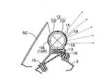
図1,4に示すように、前部カウリングCFの上縁に一体に起立されるスクリーンSCは、前記スピーカハウジング12の前方を覆い、その上縁は、そのスピーカハウジング12よりも上方に延出されていて前部スピーカ10L,10Rからのサウンドが、車体の前方に拡がらないようにしている。As shown in FIGS. 1 and 4, the screen SC that is erected integrally with the upper edge of the front cowling CF covers the front of the
図1,5,6に示すように、ライダー用シートTSの後方において車体の後部には、アームレスト20が固定され、このアームレスト20の後部にバックレスト22を支持するためのバックレスト支持部材すなわちステー21が固定されている。このステー21は、上方に向けて起立しており、そこにバックレスト受け23が固定されている。このバックレスト受け23は前後に分割可能な前半部23fと後半部23rをビス止め29して、前後方向に偏平で四角なボックス状に形成されていて、その前面にバックレスト22が支持されている。前記バックレスト受け23の上部には左右方向に長い円筒状のスピーカハウジング24が一体に形成され、このスピーカハウジング24内には、円筒状に形成される単一の後部スピーカ25が収容される。バックレスト受け23内には、後部スピーカ25と前記左右一対の前部スピーカ10L,10Rに共用されるアンプ26が収容されている。 As shown in FIGS. 1, 5, and 6, an
単一の後部スピーカ25の発声部に対応して、スピーカハウジング24の前面には、左右方向に長い長方形の開口部27が設けられ、この開口部27にはスピーカグリル28が固定されている。後部スピーカ25の発声部は、前記ライダー用シートTS上に着座するライダーRの頭部に向けられている。したがって、オーディオシステムの作動時には、後部スピーカ25からの発するサウンドは、ライダーRに向けられる。 A
図1に示すように、ライダー用シートTSの下には、底部スピーカ30がアンプ31と共に設けられ、この底部スピーカ30の発声部は、ライダー用シートTSにより覆われ、このシートTSを底部スピーカ30のサウンドの振動体として機能させることができる。 As shown in FIG. 1, a
図3に示すように、前記操向ハンドル1の左側には、オーディオシステムの、ON・OFFスイッチ、音量コントローラ、チューナなどの操作部を設けた操作盤35が設けられる。 As shown in FIG. 3, on the left side of the
前記オーディオプレーヤーAPと、各アンプ26,31はハーネス37,38により接続され、またアンプ26は、ハーネス36により前部スピーカ10L,10Rに接続される。また、オーディオプレーヤーAPと前記操作盤35の操作部とは他のハーネス39により接続される。 The audio player AP and the
つぎに、この第1実施例の作用について説明する。 Next, the operation of the first embodiment will be described.
いま、ライダーRがライダー用シートTSに着座してスクータを走行させ、その走行中に、操行ハンドル1に設けられる操作盤35上のON・OFFスイッチをON操作し、さらにチューナー、音量コントローラなどを適宜操作すれば、左右一対の前部および単一の後部スピーカ10F,10R;25からライダーRの前部および背部に向けて音声が発せられるので、ライダーRは、迫力のある立体的なサウンドを聴取してステレオ効果を楽しむことができる。特に、一対の前部スピーカ10L,10Rはバイザ3ーの上部に、また後部スピーカ25はバックレスト支持部材21の上部に設けられ、しかも、それらのスピーカ10L,10R;25の各発声部は、ライダーRの頭部前後に指向されるので、それらから発するサウンドは、障害物に妨げられることなく、ライダーRの前部および後部に集中的に発せられてステレオ効果を一層高めることができる。また、サウンドがライダーRの周囲に拡がるのを極力抑えることができ、ライダーRは走行時の交通情報などの外部情報をキャッチしにくくなることがない。さらに、左右方向に長い、左右前部スピーカ10L,10Rおよび後部スピーカ25は、ライダーRの前方および後方の視界を妨げることがない。
[第2実施例]
つぎに、本発明の第2実施例について説明する。Now, the rider R sits on the rider's seat TS and runs the scooter. During the run, the ON / OFF switch on the
[Second Embodiment]
Next, a second embodiment of the present invention will be described.
図7は、前記第1実施例の図3に対応するスクータのフロントパネル部分を示す図であり、図中前記第1実施例と同じ要素には同じ符号が付されている。 FIG. 7 is a view showing a front panel portion of the scooter corresponding to FIG. 3 of the first embodiment. In the figure, the same elements as those of the first embodiment are denoted by the same reference numerals.
この第2実施例は、左右一対の前部スピーカ110L,110Rの取付構造が前記第1実施例のものと異なっている。凹状に形成される操向走行ハンドル101は、ナビゲーション用のモニタを備えておらず、その操向ハンドル101の左右傾斜部分に跨がって一本のクロスバー101bが固定され、このクロスバー101b内には、左右一対の、棒状スピーカ110L,110Rが直列して収容されている。クロスバー101bの後側(ライダーRと対面する側)には、左右一対の前部スピーカ110L,110Rの発声部に対面して左右の細長い開口部118が開口され、この開口部118に断面円弧状のスピーカグリル119が設けられる。そして、左右一対の前部スピーカ110L,110Rの発声部は、ライダーに向けられており、それらから発するサウンドは、ライダーの頭部に指向される。In the second embodiment, the mounting structure of the pair of left and right
しかして、この第2実施例のものも前記第1実施例のものと同じ作用効果を奏する。 Thus, the second embodiment also has the same effects as the first embodiment.
なお、第1、2実施例において、オーディオプレーヤーAPは、トランクTRに収容する代わりにライダーR自身が携帯するようにしてもよく、また、前記左右前部および後部スピーカ10L,10R;25の音量を、スクータの走行速度に応じて増減できるように自動制御するようにしてもよい。 In the first and second embodiments, the audio player AP may be carried by the rider R himself instead of being housed in the trunk TR, and the volume of the left and right front and
以上、本発明の好適な実施例について説明したが、本発明はその実施例に限定されることなく、本発明の範囲内で種々の実施例が可能である。 The preferred embodiments of the present invention have been described above, but the present invention is not limited to these embodiments, and various embodiments are possible within the scope of the present invention.
たとえば、前記実施例では、本発明スピーカ取付構造を、スクータに設けた場合を説明したが、これを他の自動二輪車に設けてもよいことは勿論である。For example, in the above embodiment, the present invention speaker mounting structure, a case has been described provided to the scooter, it isRu course der that this may be provided to other motorcycles.
10L,10R・・・前部スピーカ
110L,110R・前部スピーカ
12・・・・・・・・スピーカーハウジング
14・・・・・・・・スピーカー収納部
18,118・・・・開口部
101・・・・・・・操向ハンドル
101b・・・・・・クロスバー
R・・・・・・・・・ライダー
TS・・・・・・・・シート10L, 10R ...
12 ... Speaker housing
14 ... Speaker compartment
18, 118 ... Opening 101... Steering
Claims (3)
Translated fromJapanese車体前部に、左右方向に細長いスピーカー収納部(14)を備えた、一本のスピーカーハウジング(12)を設け、このスピーカーハウジング(12)のスピーカー収納部(14)内に、左右一対の前部スピーカー(10L,10R)を、車体の左右方向に直列して収容し、そのスピーカーハウジング(12)の、シート(TS)上に着座するライダー(R)に対面する後側には、左右方向に長い開口部(18)を設け、この開口部(18)に、前記左右一対の前部スピーカー(10L,10R)の発声部を対向させ、その発声部を開口部(18)を介してライダー(R)に向けて指向させたことを特徴とする、自動二輪車のスピーカ取付構造。An audio system speaker mounting structure for a motorcycle,
A single speaker housing (12) having a speaker housing portion (14) elongated in the left-right direction is provided at the front of the vehicle body, and a pair of left and right fronts are placed in the speaker housing portion (14) of the speaker housing (12). The speaker (10L, 10R) is housed in series in the left-right direction of the vehicle body, and the rear side of the speaker housing (12) facing the rider (R) seated on the seat (TS) A long opening (18) is provided in the opening (18), and the utterances of the pair of left and right front speakers (10L, 10R) are opposed to the opening (18), and the utterance is passed through the opening (18). A speaker mounting structure for a motorcycle, characterizedby being directed toward (R) .
ライダー(R)の着座するシート(TS)よりも前方で、車体前部の左右方向の中央部に、左右方向に細長い筒形状の一本のスピーカーハウジング(12)を設け、このスピーカーハウジング(12)内に左右に細長い筒形状のスピーカー収納部(14)を設け、このスピーカー収納部(14)内に、左右一対の前部スピーカー(10L,10R)を車体の左右方向に直列して収容し、これらのスピーカー(10L,10R)の発声部をスピーカーハウジング(12)の後側に対向させ、スピーカーハウジング(12)の後側に左右方向に長い開口部(18)を設けて、前部スピーカー(10L,10R)の発声部を、開口部(18)を通してシート(TS)上に着座するライダー(R)に指向させ、前記スピーカーハウジング(12)はスピーカー収納部よりも下方に延びる取付部を介して車体に取り付けられていることを特徴とする、自動二輪車のスピーカ取付構造。An audio system speaker mounting structure for a motorcycle,
In front of the seat (TS) on which the rider (R) is seated, a single speaker housing (12) that is elongated in the left-right direction is provided at the center in the left-right direction of the front part of the vehicle body. ) Is provided with an elongated cylindrical speaker storage portion (14) on the left and right, and a pair of left and right front speakers (10L, 10R) are stored in series in the left-right direction of the vehicle body in the speaker storage portion (14). The sound generation part of these speakers (10L, 10R) is opposed to the rear side of the speaker housing (12), and a long opening part (18) in the left-right direction is provided on the rear side of the speaker housing (12). (10L, 10R) is directed to the rider (R) seated on the seat (TS) through the opening (18), and the speaker housing (12) is Characterized inthat attached to the vehicle body through a mounting portion extending below the manufacturers accommodating portion, the motorcycle speaker mounting structure.
ライダー(R)の着座するシート(TS)よりも前方で、車体前部に操向可能に支持した操向ハンドル(101)に、左右方向に細長い一本のクロスバー(101b)を設け、このクロスバー(101b)内に左右に細長いスピーカー収納部を設け、このスピーカー収納部内に、左右一対の、棒状の前部スピーカー(110L,110R)を車体の左右方向に直列して収容し、これらのスピーカー(110L,110R)の発声部を一本のクロスバー(101b)の後側に対向させ、クロスバー(101b)の後側に左右方向に長い開口部(118)を設けて、前部スピーカー(110L,110R)の発声部を、開口部(118)を通してシート(TS)上に着座するライダー(R)に指向させたことを特徴とする、自動二輪車のスピーカ取付構造。An audio system speaker mounting structure for a motorcycle,
A steering bar (101) that is steerably supported at the front of the vehicle body in front of the seat (TS) on which the rider (R) is seated is provided with a cross bar (101b) that is elongated in the left-right direction. In the crossbar (101b), there are provided elongated speaker storage portions on the left and right, and a pair of left and right rod-shaped front speakers (110L, 110R) are stored in series in the left-right direction of the vehicle body. The speaker (110L, 110R) is made to face the rear side of one cross bar (101b), and a long opening (118) in the left-right direction is provided on the rear side of the cross bar (101b). (110L, 110R) the utterance portion, characterized inthat is directed to the rider sits (R) opening through (118) on the sheet (TS), the motorcycle speaker With structure.
Priority Applications (1)
| Application Number | Priority Date | Filing Date | Title |
|---|---|---|---|
| JP2003353813AJP4252877B2 (en) | 2003-10-14 | 2003-10-14 | Motorcycle speaker mounting structure |
Applications Claiming Priority (1)
| Application Number | Priority Date | Filing Date | Title |
|---|---|---|---|
| JP2003353813AJP4252877B2 (en) | 2003-10-14 | 2003-10-14 | Motorcycle speaker mounting structure |
Publications (2)
| Publication Number | Publication Date |
|---|---|
| JP2005119352A JP2005119352A (en) | 2005-05-12 |
| JP4252877B2true JP4252877B2 (en) | 2009-04-08 |
Family
ID=34611997
Family Applications (1)
| Application Number | Title | Priority Date | Filing Date |
|---|---|---|---|
| JP2003353813AExpired - Fee RelatedJP4252877B2 (en) | 2003-10-14 | 2003-10-14 | Motorcycle speaker mounting structure |
Country Status (1)
| Country | Link |
|---|---|
| JP (1) | JP4252877B2 (en) |
Families Citing this family (3)
| Publication number | Priority date | Publication date | Assignee | Title |
|---|---|---|---|---|
| JP4579081B2 (en)* | 2005-07-29 | 2010-11-10 | 本田技研工業株式会社 | Audio device arrangement structure for motorcycles |
| JP5560082B2 (en)* | 2010-03-31 | 2014-07-23 | 本田技研工業株式会社 | Information provision system for motorcycles |
| PH12016000481B1 (en)* | 2016-01-08 | 2020-02-12 | Honda Motor Co Ltd | Vehicle |
- 2003
- 2003-10-14JPJP2003353813Apatent/JP4252877B2/ennot_activeExpired - Fee Related
Also Published As
| Publication number | Publication date |
|---|---|
| JP2005119352A (en) | 2005-05-12 |
Similar Documents
| Publication | Publication Date | Title |
|---|---|---|
| JP4559125B2 (en) | Motorcycle navigation system layout structure | |
| JPH042869Y2 (en) | ||
| JP5560082B2 (en) | Information provision system for motorcycles | |
| CN114174120A (en) | Audio systems for utility vehicles | |
| JP5534744B2 (en) | Ram duct unit | |
| JP4433464B2 (en) | Motorcycle sound equipment | |
| JP4252877B2 (en) | Motorcycle speaker mounting structure | |
| US20050121935A1 (en) | Stereophonic fairing accessory | |
| JP5882803B2 (en) | Saddle riding | |
| JPWO2019207774A1 (en) | Airbag device for saddle-riding vehicles | |
| JP4579081B2 (en) | Audio device arrangement structure for motorcycles | |
| JP3960077B2 (en) | Small electric vehicle | |
| US8121308B2 (en) | Arrangement structure of sound system in motorcycle | |
| JP5325634B2 (en) | Saddle riding | |
| JP4019727B2 (en) | Small electric vehicle | |
| JP5032135B2 (en) | Acoustic device for motorcycles | |
| JP6648301B2 (en) | Top case with built-in acoustic speaker structure | |
| US20050123148A1 (en) | Motorcycle audio system | |
| JP6759268B2 (en) | Saddle-type vehicle meter peripheral structure | |
| JP2005117588A (en) | Two-wheeled vehicle acoustic system | |
| JPH0234156Y2 (en) | ||
| JPH0584118B2 (en) | ||
| JP2004345627A (en) | Speaker mounting structure for saddle-riding type vehicle | |
| JP2012116407A (en) | Structure for arranging speaker of motorcycle | |
| JP2009260525A (en) | Speaker system |
Legal Events
| Date | Code | Title | Description |
|---|---|---|---|
| A621 | Written request for application examination | Free format text:JAPANESE INTERMEDIATE CODE: A621 Effective date:20051117 | |
| A977 | Report on retrieval | Free format text:JAPANESE INTERMEDIATE CODE: A971007 Effective date:20080612 | |
| A131 | Notification of reasons for refusal | Free format text:JAPANESE INTERMEDIATE CODE: A131 Effective date:20080618 | |
| A521 | Written amendment | Free format text:JAPANESE INTERMEDIATE CODE: A523 Effective date:20080812 | |
| TRDD | Decision of grant or rejection written | ||
| A01 | Written decision to grant a patent or to grant a registration (utility model) | Free format text:JAPANESE INTERMEDIATE CODE: A01 Effective date:20090114 | |
| A01 | Written decision to grant a patent or to grant a registration (utility model) | Free format text:JAPANESE INTERMEDIATE CODE: A01 | |
| A61 | First payment of annual fees (during grant procedure) | Free format text:JAPANESE INTERMEDIATE CODE: A61 Effective date:20090122 | |
| R150 | Certificate of patent or registration of utility model | Free format text:JAPANESE INTERMEDIATE CODE: R150 | |
| FPAY | Renewal fee payment (event date is renewal date of database) | Free format text:PAYMENT UNTIL: 20120130 Year of fee payment:3 | |
| S111 | Request for change of ownership or part of ownership | Free format text:JAPANESE INTERMEDIATE CODE: R313113 | |
| FPAY | Renewal fee payment (event date is renewal date of database) | Free format text:PAYMENT UNTIL: 20120130 Year of fee payment:3 | |
| R350 | Written notification of registration of transfer | Free format text:JAPANESE INTERMEDIATE CODE: R350 | |
| FPAY | Renewal fee payment (event date is renewal date of database) | Free format text:PAYMENT UNTIL: 20130130 Year of fee payment:4 | |
| FPAY | Renewal fee payment (event date is renewal date of database) | Free format text:PAYMENT UNTIL: 20130130 Year of fee payment:4 | |
| FPAY | Renewal fee payment (event date is renewal date of database) | Free format text:PAYMENT UNTIL: 20140130 Year of fee payment:5 | |
| LAPS | Cancellation because of no payment of annual fees |