JP4247747B2 - Image forming apparatus and developing cartridge - Google Patents
Image forming apparatus and developing cartridgeDownload PDFInfo
- Publication number
- JP4247747B2 JP4247747B2JP2005013179AJP2005013179AJP4247747B2JP 4247747 B2JP4247747 B2JP 4247747B2JP 2005013179 AJP2005013179 AJP 2005013179AJP 2005013179 AJP2005013179 AJP 2005013179AJP 4247747 B2JP4247747 B2JP 4247747B2
- Authority
- JP
- Japan
- Prior art keywords
- developer
- image forming
- developing
- forming apparatus
- development
- Prior art date
- Legal status (The legal status is an assumption and is not a legal conclusion. Google has not performed a legal analysis and makes no representation as to the accuracy of the status listed.)
- Expired - Fee Related
Links
- 238000011161developmentMethods0.000claimsdescription47
- 238000003860storageMethods0.000claimsdescription26
- 238000006073displacement reactionMethods0.000claimsdescription7
- 238000005520cutting processMethods0.000claimsdescription2
- 238000001514detection methodMethods0.000description82
- 238000000034methodMethods0.000description74
- 238000000926separation methodMethods0.000description56
- 230000015572biosynthetic processEffects0.000description35
- 238000003825pressingMethods0.000description22
- 238000012545processingMethods0.000description10
- 239000010410layerSubstances0.000description9
- 238000012546transferMethods0.000description9
- 230000005540biological transmissionEffects0.000description7
- 230000001276controlling effectEffects0.000description7
- 230000001105regulatory effectEffects0.000description7
- 238000010438heat treatmentMethods0.000description6
- 230000000903blocking effectEffects0.000description4
- 239000003795chemical substances by applicationSubstances0.000description4
- 238000010586diagramMethods0.000description4
- 229910052751metalInorganic materials0.000description4
- 239000002184metalSubstances0.000description4
- 230000002093peripheral effectEffects0.000description4
- PPBRXRYQALVLMV-UHFFFAOYSA-NStyreneChemical groupC=CC1=CC=CC=C1PPBRXRYQALVLMV-UHFFFAOYSA-N0.000description3
- 238000004140cleaningMethods0.000description3
- 230000010365information processingEffects0.000description3
- 239000000178monomerSubstances0.000description3
- 229920002379silicone rubberPolymers0.000description3
- 239000004945silicone rubberSubstances0.000description3
- 210000001364upper extremityAnatomy0.000description3
- 229920006311Urethane elastomerPolymers0.000description2
- NIXOWILDQLNWCW-UHFFFAOYSA-Nacrylic acid groupChemical groupC(C=C)(=O)ONIXOWILDQLNWCW-UHFFFAOYSA-N0.000description2
- 125000000217alkyl groupChemical group0.000description2
- 239000011248coating agentSubstances0.000description2
- 238000000576coating methodMethods0.000description2
- 239000013013elastic materialSubstances0.000description2
- 238000012423maintenanceMethods0.000description2
- 238000004519manufacturing processMethods0.000description2
- 239000000463materialSubstances0.000description2
- 239000011347resinSubstances0.000description2
- 229920005989resinPolymers0.000description2
- 238000003756stirringMethods0.000description2
- 230000001360synchronised effectEffects0.000description2
- 238000012360testing methodMethods0.000description2
- SMZOUWXMTYCWNB-UHFFFAOYSA-N2-(2-methoxy-5-methylphenyl)ethanamineChemical compoundCOC1=CC=C(C)C=C1CCNSMZOUWXMTYCWNB-UHFFFAOYSA-N0.000description1
- NIXOWILDQLNWCW-UHFFFAOYSA-MAcrylateChemical compound[O-]C(=O)C=CNIXOWILDQLNWCW-UHFFFAOYSA-M0.000description1
- OKTJSMMVPCPJKN-UHFFFAOYSA-NCarbonChemical compound[C]OKTJSMMVPCPJKN-UHFFFAOYSA-N0.000description1
- JOYRKODLDBILNP-UHFFFAOYSA-NEthyl urethaneChemical compoundCCOC(N)=OJOYRKODLDBILNP-UHFFFAOYSA-N0.000description1
- PXGOKWXKJXAPGV-UHFFFAOYSA-NFluorineChemical compoundFFPXGOKWXKJXAPGV-UHFFFAOYSA-N0.000description1
- CERQOIWHTDAKMF-UHFFFAOYSA-MMethacrylateChemical compoundCC(=C)C([O-])=OCERQOIWHTDAKMF-UHFFFAOYSA-M0.000description1
- 230000002159abnormal effectEffects0.000description1
- 229920000122acrylonitrile butadiene styrenePolymers0.000description1
- 229910052782aluminiumInorganic materials0.000description1
- XAGFODPZIPBFFR-UHFFFAOYSA-NaluminiumChemical compound[Al]XAGFODPZIPBFFR-UHFFFAOYSA-N0.000description1
- 238000007664blowingMethods0.000description1
- 229910052799carbonInorganic materials0.000description1
- 230000015556catabolic processEffects0.000description1
- 238000006243chemical reactionMethods0.000description1
- 239000011247coating layerSubstances0.000description1
- 238000004891communicationMethods0.000description1
- 239000004020conductorSubstances0.000description1
- 230000007547defectEffects0.000description1
- 238000006731degradation reactionMethods0.000description1
- 229920001971elastomerPolymers0.000description1
- 238000005562fadingMethods0.000description1
- 239000010419fine particleSubstances0.000description1
- 229910052731fluorineInorganic materials0.000description1
- 239000011737fluorineSubstances0.000description1
- 229910052736halogenInorganic materials0.000description1
- 150000002367halogensChemical class0.000description1
- 230000002427irreversible effectEffects0.000description1
- 239000004973liquid crystal related substanceSubstances0.000description1
- 238000012986modificationMethods0.000description1
- 230000004048modificationEffects0.000description1
- 230000003287optical effectEffects0.000description1
- 229920000515polycarbonatePolymers0.000description1
- 239000004417polycarbonateSubstances0.000description1
- -1polyethylene terephthalatePolymers0.000description1
- 229920000139polyethylene terephthalatePolymers0.000description1
- 239000005020polyethylene terephthalateSubstances0.000description1
- 238000006116polymerization reactionMethods0.000description1
- 238000010557suspension polymerization reactionMethods0.000description1
- WFKWXMTUELFFGS-UHFFFAOYSA-NtungstenChemical compound[W]WFKWXMTUELFFGS-UHFFFAOYSA-N0.000description1
- 229910052721tungstenInorganic materials0.000description1
- 239000010937tungstenSubstances0.000description1
- 238000011144upstream manufacturingMethods0.000description1
- 238000010792warmingMethods0.000description1
Images


Classifications
- G—PHYSICS
- G03—PHOTOGRAPHY; CINEMATOGRAPHY; ANALOGOUS TECHNIQUES USING WAVES OTHER THAN OPTICAL WAVES; ELECTROGRAPHY; HOLOGRAPHY
- G03G—ELECTROGRAPHY; ELECTROPHOTOGRAPHY; MAGNETOGRAPHY
- G03G15/00—Apparatus for electrographic processes using a charge pattern
- G03G15/80—Details relating to power supplies, circuits boards, electrical connections
- G—PHYSICS
- G03—PHOTOGRAPHY; CINEMATOGRAPHY; ANALOGOUS TECHNIQUES USING WAVES OTHER THAN OPTICAL WAVES; ELECTROGRAPHY; HOLOGRAPHY
- G03G—ELECTROGRAPHY; ELECTROPHOTOGRAPHY; MAGNETOGRAPHY
- G03G15/00—Apparatus for electrographic processes using a charge pattern
- G03G15/06—Apparatus for electrographic processes using a charge pattern for developing
- G03G15/08—Apparatus for electrographic processes using a charge pattern for developing using a solid developer, e.g. powder developer
- G03G15/0896—Arrangements or disposition of the complete developer unit or parts thereof not provided for by groups G03G15/08 - G03G15/0894
- G—PHYSICS
- G03—PHOTOGRAPHY; CINEMATOGRAPHY; ANALOGOUS TECHNIQUES USING WAVES OTHER THAN OPTICAL WAVES; ELECTROGRAPHY; HOLOGRAPHY
- G03G—ELECTROGRAPHY; ELECTROPHOTOGRAPHY; MAGNETOGRAPHY
- G03G2215/00—Apparatus for electrophotographic processes
- G03G2215/06—Developing structures, details
- G03G2215/066—Toner cartridge or other attachable and detachable container for supplying developer material to replace the used material
- G—PHYSICS
- G03—PHOTOGRAPHY; CINEMATOGRAPHY; ANALOGOUS TECHNIQUES USING WAVES OTHER THAN OPTICAL WAVES; ELECTROGRAPHY; HOLOGRAPHY
- G03G—ELECTROGRAPHY; ELECTROPHOTOGRAPHY; MAGNETOGRAPHY
- G03G2221/00—Processes not provided for by group G03G2215/00, e.g. cleaning or residual charge elimination
- G03G2221/16—Mechanical means for facilitating the maintenance of the apparatus, e.g. modular arrangements and complete machine concepts
- G03G2221/1663—Mechanical means for facilitating the maintenance of the apparatus, e.g. modular arrangements and complete machine concepts having lifetime indicators
Landscapes
- Physics & Mathematics (AREA)
- General Physics & Mathematics (AREA)
- Dry Development In Electrophotography (AREA)
- Electrophotography Configuration And Component (AREA)
- Control Or Security For Electrophotography (AREA)
Description
Translated fromJapanese本発明は、画像形成装置及び現像カートリッジに関する。 The present invention relates to an image forming apparatus and a developing cartridge.
一般に、画像形成装置は、トナーを収容するトナーカートリッジが着脱可能に設けられている。そして、例えば、トナーカートリッジ内のトナー残量が所定量以下になると、被記録媒体上にトナーが十分に転写されず、いわゆる印刷かすれが生じるおそれがある。また、トナーカートリッジ内のトナーが劣化(帯電性能の低下)すると、被記録媒体上の適切な位置にトナーが転写されず、いわゆる印刷かぶりが生じるおそれがある。 In general, an image forming apparatus is detachably provided with a toner cartridge that accommodates toner. For example, when the remaining amount of toner in the toner cartridge becomes a predetermined amount or less, the toner is not sufficiently transferred onto the recording medium, and so-called print fading may occur. Further, when the toner in the toner cartridge is deteriorated (charging performance is lowered), the toner is not transferred to an appropriate position on the recording medium, and so-called printing fog may occur.
そこで、下記特許文献1には、上記トナーカートリッジの交換時期を判定する画像形成装置が開示されている。具体的には、新たなトナーカートリッジが画像形成装置本体に装着されてからのトナー補給時間等を計時して所定時間になったときに交換時期が到来したとして記録動作(画像形成動作)を禁止する構成になっている。
ところが、交換時期が到来して取り外された旧トナーカートリッジは、廃棄するまでオフィス等で新品のトナーカートリッジと同じ場所に保管されることがあり、誤って画像形成装置本体や他の同じ機種の画像形成装置本体に再び装着されることがある。そうすると、上記特許文献1のものでは、この旧トナーカートリッジを新たに装着した時点からのトナー補給時間等に基づき交換時期を判定するため、このまま記録動作が許容され、上記画像形成不良が発生する可能性が非常に高くなる。要するに、特許文献1の構成は、新品のトナーカートリッジが装着された場合にはその交換時期を的確に判定できるものの、一旦使用されたトナーカートリッジが装着された場合にはその交換時期を的確に把握することができず、そのまま記録動作が実行されて画像形成不良が発生してしまうのである。 However, old toner cartridges that have been removed due to replacement may be stored in the same place as new toner cartridges in the office or the like until they are discarded. It may be mounted again on the forming apparatus body. Then, in the above-mentioned patent document 1, since the replacement time is determined based on the toner replenishment time from the time when the old toner cartridge is newly mounted, the recording operation is allowed as it is, and the image formation failure may occur. The sex becomes very high. In short, the configuration of Patent Document 1 can accurately determine the replacement timing when a new toner cartridge is mounted, but accurately grasps the replacement timing when a used toner cartridge is mounted. As a result, the recording operation is performed as it is, and an image formation defect occurs.
本発明は上記のような事情に基づいて完成されたものであって、その目的は、寿命が到来した現像カートリッジが再使用されても画質の劣化した画像が形成されることを防止可能な画像形成装置及び現像カートリッジを提供するところにある。 The present invention has been completed based on the above-described circumstances, and an object of the present invention is to prevent an image having a deteriorated image quality from being formed even when a developing cartridge whose lifetime has come to an end is reused. A forming apparatus and a developing cartridge are provided.
上記の目的を達成するための手段として、請求項1の発明に係る画像形成装置は、画像形成装置本体と、当該画像形成装置本体に着脱可能に装着される現像カートリッジと、を備える画像形成装置であって、前記現像カートリッジは、現像剤を収容する現像剤収容室と、現像バイアスが印加される現像側電極と、前記現像側電極に印加された現像バイアスを受けることで前記現像剤収容室内の現像剤を像担持体に供給する現像剤担持体と、前記現像側電極と前記現像剤担持体との間を電気的に接続するヒューズ素子と、前記像担持体と前記現像剤担持体とを接離可能に変位させる変位手段と、前記像担持体と前記現像剤担持体とが離間した状態で当該現像剤担持体と接触する接地電極と、を有し、前記画像形成装置本体は、前記現像カートリッジの寿命到来か否かを判断する判断手段と、前記現像側電極に前記現像バイアスを印加する印加手段と、前記変位手段を制御して、画像形成動作時に前記像担持体と前記現像剤担持体とを接触させる一方で、非画像形成動作時に前記像担持体と前記現像剤担持体とを離間させる制御手段と、前記判断手段で前記寿命到来と判断された場合に、前記非画像形成動作時に前記現像側電極を介して前記ヒューズ素子に溶断電流を流して前記現像側電極と前記現像剤担持体との間の通電を遮断する実行手段と、を有することを特徴とする。
なお、本発明の「画像形成装置」は、プリンタ(例えばレーザプリンタ)などの印刷装置だけでなく、ファクシミリ装置や、プリンタ機能及びスキャナ機能等を備えた複合機であってもよい。
「像担持体」は、感光ドラム(感光体)以外に、中間転写体であってもよい。また、当該像担持体は、現像カートリッジ側に設けられたものであってもよいし、画像形成装置本体側に設けられたものであってもよい。As means for achieving the above object, an image forming apparatus according to the invention of claim 1 comprises an image forming apparatus main body and a developing cartridge detachably mounted on the image forming apparatus main body. The developer cartridge includes a developer storage chamber for storing a developer, a development side electrode to which a development bias is applied, and a development bias applied to the development side electrode to receive the development bias. A developer carrier for supplying the developer to the image carrier,a fuse element for electrically connectingthe development-side electrode and the developer carrier, theimage carrier and the developer carrier, And a grounding electrode that contacts the developer carrier in a state where the image carrier and the developer carrier are separated from each other, and the image forming apparatus main body includes: The developing cartridge Determining means for determining whether di lifetime incoming and applying means for applying the developing bias to the developing-side electrode,by controlling the displacement means, the developer carrier and the image carrier during image formation operation The non-image forming operation when it is determined that the life has cometo an end by the control means for separating the image carrier and the developer carrier from each other during the non-image forming operation. And an execution meansfor cutting off the energization between the development side electrode and the developer carrying member by causing a fusing current to flow through the fuse element through the development side electrode .
The “image forming apparatus” of the present invention is not limited to a printing apparatus such as a printer (for example, a laser printer), but may be a facsimile machine or a multifunction machine having a printer function and a scanner function.
The “image carrier” may be an intermediate transfer member in addition to the photosensitive drum (photosensitive member). In addition, the image carrier may be provided on the developing cartridge side or may be provided on the image forming apparatus main body side.
請求項2の発明は、請求項1に記載の画像形成装置において、前記実行手段は、前記現像側電極を介して前記ヒューズ素子に溶断電流を流すことを特徴とする。According to asecond aspect of the invention, in the image forming apparatus according to claim1, wherein the execution means is characterized by passing a fusing current to the fuse element via the development-side electrode.
請求項3の発明は、画像形成装置本体と、当該画像形成装置本体に着脱可能に装着される現像カートリッジと、を備える画像形成装置であって、前記現像カートリッジは、現像剤を収容する現像剤収容室と、現像バイアスが印加される現像側電極と、前記現像側電極に印加された現像バイアスを受けることで前記現像剤収容室内の現像剤を像担持体に供給する現像剤担持体と、前記現像側電極と前記現像剤担持体との間を電気的に接続し、復帰不能な遮断動作によって両者間の通電を遮断する通電遮断手段と、を有し、前記画像形成装置本体は、前記現像カートリッジの寿命到来か否かを判断する判断手段と、前記現像側電極に前記現像バイアスを印加する印加手段と、前記判断手段で前記寿命到来と判断された場合に、前記通電遮断手段に前記遮断動作を実行させる実行手段と、を有し、前記通電遮断手段は、前記現像側電極と前記現像剤担持体との間を開閉可能に接続するスイッチ手段であり、前記実行手段は、前記スイッチ手段に開動作させるアクチュエータであることを特徴とする。According to a third aspect of the present invention, there is provided animage forming apparatus comprising: animage forming apparatus main body; and a developing cartridge detachably attached to the image forming apparatus main body, wherein the developing cartridge contains a developer. A storage chamber, a development side electrode to which a development bias is applied, a developer carrier that supplies the developer in the developer storage chamber to the image carrier by receiving a development bias applied to the development side electrode; The image forming apparatus main body includes an energization interruption unit that electrically connects between the development side electrode and the developer carrier and interrupts energization between the two by an irreversible interruption operation. A determination means for determining whether or not the life of the developing cartridge has been reached; an application means for applying the development bias to the development side electrode; and when the determination means determines that the life has expired, Has an execution unit for executing the serial interruption operation, and the current interrupting means, wherein a switching means for openably connecting the development-side electrode and the developer carrying member, said executing means, said It is an actuator that causes the switch means to open.
請求項4の発明は、請求項1〜請求項3のいずれかに記載の画像形成装置において、前記現像剤担持体は、回転して前記像担持体に現像剤を供給する現像ローラであり、前記判断手段は、前記現像ローラ又は当該現像ローラの回転に伴って回転する前記像担持体としての感光ドラムの回転数をカウントする回転数センサを有し、当該回転数センサにおけるカウント回転数が限界数に達した場合に前記寿命到来と判断することを特徴とする。According to afourth aspect of the present invention, in the image forming apparatus according to any one of the first tothird aspects, the developer carrier is a developing roller that rotates and supplies the developer to the image carrier. The determination means includes a rotation speed sensor that counts the rotation speed of the developing roller or the photosensitive drum as the image carrier that rotates as the development roller rotates, and the count rotation speed of the rotation speed sensor is limited. It is characterized in that it is determined that the lifetime has come when the number is reached.
請求項5の発明は、請求項4に記載の画像形成装置において、前記判断手段は、更に、前記現像剤収容室内の現像剤残量が限界量以下になったか否かを検出する現像剤センサを有し、当該現像剤センサで現像剤残量が限界量以下であると検出されたとき、又は、前記カウント回転数が限界数に達したときに前記寿命到来と判断することを特徴とする。According to afifth aspect of the present invention, in the image forming apparatus according to thefourth aspect , the determination means further detects whether or not the remaining amount of the developer in the developer accommodating chamber has become a limit amount or less. When the developer sensor detects that the remaining amount of developer is less than the limit amount, or when the count rotation speed reaches the limit number, it is determined that the end of life is reached. .
<請求項1の発明>
本構成によれば、寿命到来と判断された現像カートリッジは、通電遮断手段によって現像側電極と現像剤担持体との間の通電が遮断される。従って、この現像カートリッジを誤って例えば他の同じ機種の画像形成装置本体に誤って装着しても現像バイアスが現像剤担持体に印加されることはなく、寿命到来した現像カートリッジを装着してしまったことを知ることができ、再使用されても画質の劣化した画像が形成されることを防止できる。
例えば、現像カートリッジにその寿命情報等を記録させたICタグを設けて、そのICタグの情報に基づき現像カートリッジの寿命到来を判断する構成も考えられるが、この構成では、その現像カートリッジの再利用する場合には、ICタグの情報をリセットするための装置が必要となる。
これに対して、本構成では、ヒューズを交換し、現像剤を再注入することで現像カートリッジを容易に再利用することができる。
また、現像剤担持体と像担持体とを、画像形成動作時には接触させる一方で、非画像形成動作時(例えば画像形成開始前の待機状態)には離間させるようにしている。そして、この非画像形成動作時に、現像側電極と、現像剤担持体に接触する接地電極との間に溶断電流を流してヒューズ素子に遮断動作を実行させるようにしている。このように、ウォーミングアップ動作などの待機状態にあるときに現像剤担持体と像担持体とを離間させることにより、現像剤が現像剤担持体から像担持体へ転移することを防止できる。<Invention of Claim 1>
According to this configuration, in the developing cartridge determined to have reached the end of its life, the energization between the development side electrode and the developer carrying member is interrupted by the energization interrupting means. Therefore, even if the developing cartridge is mistakenly attached to, for example, another image forming apparatus main body of the same model, the developing bias is not applied to the developer carrying member, and the developing cartridge that has reached the end of its life is attached. Thus, it is possible to prevent an image with a deteriorated image quality from being formed even if it is reused.
For example, it is possible to provide an IC tag having life information recorded on the developing cartridge and determine the end of the life of the developing cartridge based on the information on the IC tag. In this structure, however, the developing cartridge can be reused. In this case, a device for resetting the information of the IC tag is required.
In contrast, in this configuration, the developing cartridge can be easily reused by replacing the fuse and reinjecting the developer.
In addition, the developer carrying member and the image carrying member are brought into contact with each other during the image forming operation, while being separated from each other during the non-image forming operation (for example, a standby state before the start of image formation). During this non-image forming operation, a fusing current is passed between the developing side electrode and the ground electrode in contact with the developer carrying member to cause the fuse element to perform a blocking operation. As described above, when the developer carrier and the image carrier are separated in a standby state such as a warm-up operation, the developer can be prevented from transferring from the developer carrier to the image carrier.
<請求項3の発明>
例えば、現像カートリッジにその寿命情報等を記録させたICタグを設けて、そのICタグの情報に基づき現像カートリッジの寿命到来を判断する構成も考えられるが、この構成では、その現像カートリッジの再利用する場合には、ICタグの情報をリセットするための装置が必要となる。
これに対して、本構成では、スイッチ手段のリセット操作をし、現像剤を再注入することで現像カートリッジを容易に再利用することができる。<Invention of Claim3 >
For example, it is possible to provide an IC tag having life information recorded on the developing cartridge and determine the end of the life of the developing cartridge based on the information on the IC tag. In this structure, however, the developing cartridge can be reused. In this case, a device for resetting the information of the IC tag is required.
On the other hand, in this configuration, the developer cartridge can be easily reused by resetting the switch means and reinjecting the developer.
<請求項2の発明>
本構成では、現像バイアス及びヒューズ素子への溶断電流を共通の現像側電極を介して与えるようにすることで、現像カートリッジの構成を簡略化することができる。<Invention of Claim2 >
In this configuration, the configuration of the developing cartridge can be simplified by providing the developing bias and the fusing current to the fuse element via the common developing-side electrode.
<請求項4,5の発明>
判断手段の具体的構成として、請求項3では、現像ローラ又は感光ドラムの回転数が予め設定された限界数に達した場合に寿命到来と判断する構成である。一方、請求項7では、本構成では、現像剤収容室内の現像剤残量が限界量以下になったことを検出した場合にも寿命到来と判断する構成である。現像カートリッジの寿命到来の態様は、現像剤収容室内の現像剤残量が少なくなってきて十分な現像剤を像担持体に供給できない現像剤残量不足だけではない。現像剤の残量が十分にあっても現像動作が多く実行されて現像剤収容室内の現像剤が極端に多く攪拌されることで帯電性能が低下して正常な画像形成ができない態様もある。従って、両態様に基づく寿命到来を検出できる請求項4の構成がより好ましい。<Invention of
As a specific configuration of the determination means, thethird aspect determines the end of the service life when the number of rotations of the developing roller or the photosensitive drum reaches a preset limit number. On the other hand, according to the seventh aspect, in this configuration, it is determined that the end of the service life is reached even when it is detected that the remaining amount of the developer in the developer storage chamber is below the limit amount. The mode of the end of the life of the developing cartridge is not only the shortage of the remaining amount of the developer in which the remaining amount of the developer in the developer containing chamber becomes small and sufficient developer cannot be supplied to the image carrier. There is also an aspect in which even if the remaining amount of the developer is sufficient, a large number of developing operations are performed and the developer in the developer containing chamber is agitated so much that charging performance is deteriorated and normal image formation cannot be performed. Therefore, the structure of Claim4 which can detect the lifetime arrival based on both aspects is more preferable.
<実施形態1>
本発明の実施形態1を図1〜図21を参照しつつ説明する。
1.レーザプリンタの全体構成
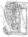
図1は、本発明の画像形成装置としてのレーザプリンタを示す要部側断面図である。
図1において、レーザプリンタ1は、本体フレーム2内において、被記録媒体としての用紙3を供給するためのフィーダ部4、給紙された用紙3に画像を形成するための画像形成部5を備えている。<Embodiment 1>
Embodiment 1 of the present invention will be described with reference to FIGS.
1. FIG. 1 is a side sectional view of an essential part showing a laser printer as an image forming apparatus of the present invention.
In FIG. 1, a laser printer 1 includes a feeder unit 4 for supplying a sheet 3 as a recording medium and an
(1)フィーダ部
フィーダ部4は、本体フレーム2内の底部に、着脱可能に装着される給紙トレイ6と、給紙トレイ6の一端部(以下、この一端部を前側、その反対側を後側とする。)に設けられる給紙機構部7と、給紙機構部7に対し用紙3の搬送方向の下流側に設けられる搬送ローラ8、9及び10と、これら搬送ローラ8、9及び10に対し用紙3の搬送方向の下流側に設けられるレジストローラ11とを備えている。(1) Feeder unit The feeder unit 4 includes a paper feed tray 6 that is detachably attached to the bottom of the main body frame 2, and one end of the paper feed tray 6 (hereinafter, this one end is referred to as the front side and the opposite side thereof. The
(a)給紙トレイ
給紙トレイ6は、用紙3を積層状に収容可能な上面が開放されたボックス形状をなし、本体フレーム2の底部に対して水平方向に着脱可能に構成されている。この給紙トレイ6内には、用紙押圧板12が設けられている。用紙押圧板12は、用紙3を積層状にスタック可能になっており、給紙機構部7に対して遠い方の端部において揺動可能に支持されることによって、給紙機構部7に対して近い方の端部が上下方向に移動可能となっている。用紙押圧板12の下方には、図示しないばねが配置され、そのばねによって用紙押圧板12が上方向に付勢されている。そのため、用紙押圧板12は、用紙3の積層量が増えるに従って、給紙機構部7に対して遠い方の端部を支点として、ばねの付勢力に抗して下向きに揺動される。(A) Paper Feed Tray The paper feed tray 6 has a box shape with an open upper surface that can accommodate the sheets 3 in a stacked manner, and is configured to be detachable in the horizontal direction with respect to the bottom of the main body frame 2. A
(b)給紙機構部
給紙機構部7は、給紙ローラ13と、その給紙ローラ13に対向する分離パッド14と、分離パッド14の裏側に配置されるばね15とを備えている。給紙機構部7では、ばね15の付勢力によって、分離パッド14が給紙ローラ13に向かって押圧されている。(B) Paper Feed Mechanism Unit The paper
そして、用紙押圧板12がばねによって上方に付勢されると、用紙押圧板12上の最上位にある用紙3は、給紙ローラ13に向かって押圧される。給紙ローラ13の回転によって用紙3の先端は、給紙ローラ13と分離パッド14で挟まれ、給紙ローラ13と分離パッド14との協動により、用紙3が1枚毎に分離される。分離された用紙3は、搬送ローラ8、9及び10によってレジストローラ11に送られる。
レジストローラ11は、1対のローラから構成されており、用紙3の斜行を矯正して、画像形成位置(後述する感光ドラム99と転写ローラ101との接触部分)に送るようにしている。
なお、このレーザプリンタ1のフィーダ部4は、さらに、任意のサイズの用紙3を積層可能とするマルチパーパストレイ16と、マルチパーパストレイ16に積層される用紙3を給紙するためのマルチパーパス給紙ローラ17と、そのマルチパーパス給紙ローラ17に対向するマルチパーパス分離パッド18とを備えている。マルチパーパストレイ16は、前カバー32内に折り畳まれた状態で収容されている。When the
The
The feeder unit 4 of the laser printer 1 further includes a
(2)画像形成部
画像形成部5は、スキャナ部20、プロセスユニット21及び定着部22を備えている。
(a)スキャナ部
スキャナ部20は、本体フレーム2内の上部に設けられ、レーザ発光部(図示せず。)、回転駆動されるポリゴンミラー23、レンズ24、25、反射鏡26、27、28を備えている。そして、レーザ発光部からは、用紙3に形成すべき画像を表すプリントデータに基づき変調されたレーザビームが出射され、そのレーザビームは、図に鎖線で示すように、ポリゴンミラー23、レンズ24、反射鏡26及び27、レンズ25、反射鏡28の順に通過あるいは反射して、後述するプロセスユニット21の感光ドラム99の表面に照射される。(2) Image Forming Unit The
(A) Scanner Unit The
(b)プロセスユニット
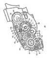
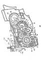
図2はプロセスユニットの側面図であり、図3は現像カートリッジの側面図であり、図4はカバー部材が取り外された現像カートリッジの側面図であり、図5は現像カートリッジの平面図である。また、図6,7は検知ギアが動力伝達位置にある現像カートリッジの側面図であり、図8,9は検知ギアが旧品位置にある現像カートリッジの側面図である。(B) Process Unit FIG. 2 is a side view of the process unit, FIG. 3 is a side view of the developing cartridge, FIG. 4 is a side view of the developing cartridge with the cover member removed, and FIG. It is a top view. 6 and 7 are side views of the developing cartridge in which the detection gear is in the power transmission position, and FIGS. 8 and 9 are side views of the developing cartridge in which the detection gear is in the old product position.
プロセスユニット21は、スキャナ部20の下方に設けられ、本体フレーム2に対して着脱自在に装着されている。すなわち、本体フレーム2は、プロセスユニット21を収容するための本体収容部30と、プロセスユニット21を本体フレーム2に対して着脱させるための本体収容部30へ通じる開口31と、開口31を被覆又は開放するための前カバー32とを備えている。 The
本体収容部30は、本体フレーム2におけるスキャナ部20の下方において、プロセスユニット21を収容できる空間として設けられている。
開口31は、本体収容部30から前カバー32に至る通路として形成されている。また、該前カバー32は、本体フレーム2の前側の前面及び上面にわたって設けられている。
この前カバー32は、閉位置と開位置との間を揺動して、開位置において、開口31を開放し、閉位置において開口31を被覆する。そして、プロセスユニット21は、前カバー32を開位置に位置させた状態で、開口31を介して、本体収容部30に対して着脱される。なお、本実施形態では、レーザプリンタ1からプロセスユニットを取り外したものが本発明でいう「画像形成装置本体」に相当する。The main
The
The
また、プロセスユニット21は、図2に示すように、本体フレーム2に対して着脱されるドラムカートリッジ33と、ドラムカートリッジ33に着脱自在に収容される現像器たる現像カートリッジ34とを備えている。 As shown in FIG. 2, the
(ア)現像カートリッジ
現像カートリッジ34は、図1に示すように、筐体35、その筐体35内に設けられる攪拌部材としてのアジテータ36、供給ローラ37、現像ローラ38及び層厚規制ブレード39を備えている。(A) Developer Cartridge As shown in FIG. 1, the
筐体35は、前壁42と、前壁42の下端部から後方に湾曲する底壁43と、底壁43の後端部から後方に延びる下壁44と、下壁44の上方に形成されるブレード支持壁45とを備えている。
これら前壁42、底壁43、下壁44及びブレード支持壁45と、これらの幅方向(前後方向と直交する方向であって筐体35の幅方向、以下同じ)両側に設けられる両側壁46及び47とが、一体成形されている。また、下壁44、ブレード支持壁45、両側壁46及び47で形成される筐体35の後側は、現像ローラ38の後側の一部が露出するように開口されている。The
Both the front wall 42, the
そして、この筐体35は、前側において、前壁42、底壁43及び両側壁46、47で囲まれる空間が、現像剤収容室としてのトナー収容室40として形成されている。また、後側において、下壁44、ブレード支持壁45及び両側壁46、47で囲まれる空間が現像室41として形成されている。また、筐体35は、この筐体35の上方開口部を被覆する上カバー48を備えている。 In the
トナー収容室40には、現像剤としてのトナーが収容されている。トナーとしては、正帯電性の非磁性1成分であって、スチレン等のスチレン系単量体や、アクリル酸、アルキル(C1〜C4)アクリレート、アルキル(C1〜C4)メタアクリレート等のアクリル系単量体に代表される重合性単量体を、懸濁重合等の公知の重合方法によって共重合させることにより得られる重合トナーが用いられている。 The
また、このトナー収容室40内には、アジテータ36が設けられている。このアジテータ36は、可撓性を有するABS樹脂等の樹脂材料からなり、軸51と、軸51に設けられる羽根部材52と、羽根部材52に設けられる可撓性のフィルム部材53と、軸51に設けられるワイパ支持部54とが、一体成形されている。なお、このアジテータ36は、トナー収容室40内において、図1における時計回りにのみ回転されるように設けられている。 An
軸51は、トナー収容室40側面視略中央において、筐体35の幅方向に沿って配置され、両側壁46及び47の間に架設されている。この軸51は、直径3〜8mmの丸棒状をなし、可撓性を有し、両側壁46及び47の間の長さよりも、長く形成されている。そして、一方の側壁46側における軸51の一方端部は、一方の側壁46を貫通して、トナー収容室40の外側に突出しており、一方の側壁46において回転可能に支持されている。また、他方の側壁47側における軸51の他方端部は、トナー収容室40内における他方の側壁47において回転可能に支持されている。 The
羽根部材52は、各側壁46及び47と接触することなく、トナー収容室40におけるアジテータ36の軸方向全域にわたって設けられている。また、フィルム部材53は、ポリエチレンテレフタレート等の樹脂フィルムからなり、羽根部材52の長手方向にわたって貼着されている。なお、フィルム部材53は、トナーを攪拌できるように、底壁43と接触して撓む長さとして設定されている。 The
また、ワイパ支持部54は、軸51の軸方向両端部において、羽根部材52の突出方向と反対方向に突出するように設けられている。各ワイパ支持部54には、次に述べるトナー残量検知用窓56を払拭するためのワイパ部材55がねじ止めされている。なお、各ワイパ部材55は、トナー残量検知用窓56を払拭するために、各側壁46及び47と弾性的に接触するように配置されている。 Further, the
また、このトナー収容室40内の両側壁46及び47には、トナー残量検知用窓56が設けられている。トナー残量検知用窓56は、トナー収容室40の後方下側において、両側壁46及び47に、それぞれ対向するように設けられている。また、このトナー残量検知用窓56には、図2,3等に示すように、両側壁46及び47における外側表面に、円筒状の光通過部57が設けられている。そして、両トナー残量検知用窓56を挟んで対向配置された光電式のトナー切れ検出センサ196(図19参照)が設けられており、トナー収容室40内のトナー残量が所定の限界量(用紙3へ十分な量のトナーが転写できず、印刷かすれが生じ得る量)になったときにトナー切れの検出信号を出力する。 In addition, toner remaining
また、このトナー収容室40の一方の側壁46には、トナー充填口58が設けられている。このトナー充填口58は、一方の側壁46の厚さ方向を貫通する円形状に形成されている。そして、トナー充填口58には、トナーがトナー収容室40に収容された状態において、キャップ59が被覆されている。 A
現像室41には、図1に示すように、供給ローラ37、現像ローラ38及び層厚規制ブレード39が設けられている。 As shown in FIG. 1, the developing chamber 41 is provided with a supply roller 37, a developing
供給ローラ37は、トナー収容室40の後方において、筐体35の幅方向に沿って設けられ、両側壁46及び47において回転可能に支持されている。この供給ローラ37は、アジテータ36の回転方向と逆方向に回転可能に設けられている。供給ローラ37は、金属製のローラ軸に、導電性のウレタンスポンジが被覆されている。 The supply roller 37 is provided behind the
現像ローラ38は、供給ローラ37の後方において、筐体35の幅方向に沿って設けられ、その一部が筐体35の後方に設けられた開口から露出するように両側壁46及び47において回転可能に支持されている。この現像ローラ38は、供給ローラ37の回転方向と同方向に回転可能に設けられている。 The developing
なお、現像ローラ38は、金属製のローラ軸38aの表面に、導電性の弾性材料、カーボン微粒子を含む導電性のウレタンゴム又はシリコーンゴムを被覆し、その弾性材料の表面に、フッ素が含有されているウレタンゴムまたはシリコーンゴムのコート層を被覆して形成される。また、現像ローラ38のローラ軸38aには、印刷動作時にバイアス印加回路198からの現像バイアスが印加される。この構成については後で詳説する。 In the developing
そして、これら供給ローラ37と現像ローラ38とは、互いに対向配置され、現像ローラ38に対して供給ローラ37がある程度圧縮するような状態で接触されている。供給ローラ37と現像ローラ38とは、それらの対向接触部分において、互いに逆方向に回転する。 The supply roller 37 and the developing
層厚規制ブレード39は、供給ローラ37の上方であって、現像ローラ38の回転方向における供給ローラ37との対向位置と感光ドラム99との対向位置との間において、筐体35のブレード支持壁45に支持されている。 The layer
この層厚規制ブレード39は、現像ローラ38の軸方向に沿って現像ローラ38と対向配置されており、板ばね部材61と、その板ばね部材61の先端部に設けられ、現像ローラ38と接触される絶縁性のシリコーンゴムからなる圧接部62とを備えている。層厚規制ブレード39は、板ばね部材61がブレード支持壁45に支持された状態で、圧接部62が板ばね部材61の弾性力によって、現像ローラ38の表面に圧接されている。 The layer
また、この現像カートリッジ34には、図4に示すように、アジテータ36、供給ローラ37、現像ローラ38を回転駆動するギヤ機構部63と、図3に示すように、このギヤ機構部63を覆うカバー部材64とが設けられている。 Further, as shown in FIG. 4, the developing
ギヤ機構部63は、図4に示すように、現像カートリッジ34の一方の側壁46の外側壁に設けられており、入力ギヤ65、供給ローラ駆動ギヤ66、現像ローラ駆動ギヤ67、第1中間ギヤ68、第2中間ギヤ69、駆動ギヤとしての第3中間ギヤ70、アジテータ駆動ギヤ71及び検知ギヤ72を備えている。 As shown in FIG. 4, the
入力ギヤ65は、一方の側壁46の外側壁における現像ローラ38とアジテータ36との間において回転可能に設けられている。この入力ギヤ65には、メインモータ200(図16参照)からの動力が入力される。 The
供給ローラ駆動ギヤ66は、入力ギヤ65の下方において、入力ギヤ65と噛み合う状態で、供給ローラ37のローラ軸の軸端部に設けられている。
現像ローラ駆動ギヤ67は、入力ギヤ65の後方側方において、入力ギヤ65と噛み合う状態で、現像ローラ38のローラ軸38aの軸端部に設けられている。The supply
The developing
第1中間ギヤ68は、入力ギヤ65の前方側方において、入力ギヤ65と噛み合うように、一方の側壁46の外側壁に回転可能に設けられている。また、第1中間ギヤ68は、入力ギヤ65と噛み合う外歯と、次に述べる第2中間ギヤ69と噛み合う内歯(図には表れない)とが、同軸で一体成形される2段ギヤとなっている。 The first
第2中間ギヤ69は、第1中間ギヤ68の上方において、第1中間ギヤ68の内歯と噛み合うように、一方の側壁46の外側壁に回転可能に設けられている。第3中間ギヤ70は、第2中間ギヤ69の前方側方において、第2中間ギヤ69の内歯(後述)と噛み合うように、一方の側壁46の外側壁に回転可能に設けられている。また、第3中間ギヤ70は、後述する検知ギヤ72と噛み合う外歯と、第2中間ギヤ69の内歯(図には表れない)とが、同軸で一体成形される2段ギヤとなっている。 The second
アジテータ駆動ギヤ71は、第3中間ギヤ70の前方斜め下方において、第3中間ギヤ70の内歯と噛み合う状態で、一方の側壁46を貫通して外側に突出しているアジテータ36の軸51の一方端部側に設けられている。 The
検知ギヤ72は、アジテータ駆動ギヤ71に対して、アジテータ36の軸方向外側であって、アジテータ駆動ギヤ71と幅方向に重なるような状態で、アジテータ36の軸51の端部に設けられている。この検知ギヤ72は、アジテータ36の軸51の回転に従って、一体で回転するように設けられている。
また、この検知ギヤ72は、検知ギヤ本体部73、ガイド部材74、欠歯ギヤとしての欠歯ギヤ部75、及び判別部材としての当接部材76を備えており、これらは一体成形されている。
検知ギヤ本体部73は、側面視略円形状の側板部77と、側板部77の周端縁からアジテータ駆動ギヤ71に向かって湾曲される略円形状の筒部78とが一体成形されている。The
The
The detection gear
側板部77には、その中心部に、側板部77を厚さ方向に貫通する円形状の孔79が設けられている。この孔79には、アジテータ36の軸51の端部が挿入され、この孔79を介して、側板部77が軸51の端部において固定されている。これにより、アジテータ36の軸51の回転に従って、検知ギヤ72が一体的に回転される。また、この孔79には、カバー部材64の後述する支持軸88も挿嵌されている。 The
なお、図4に示すように、アジテータ36の軸51と一体的に回転する検知ギヤ72(具体的には、ガイド部材74)の表面には、アジテータ36の回動位置を示す指示リブ270が設けられている。一方、現像カートリッジ34の一方の側壁46には検知ギア72の側方位置に指示リブ271が設けられている。例えば現像カートリッジ34の出荷段階においてアジテータ36がトナー収容室40内のトナー剤内に埋没していると、その輸送によってトナー剤が沈み込む。そうすると、レーザプリンタ1の駆動当初においてアジテータ36の回転抵抗が非常に高くなり好ましくない。 As shown in FIG. 4, on the surface of the detection gear 72 (specifically, the guide member 74) that rotates integrally with the
そこで、上記したように、指示リブ270,271を設けて、例えば製造段階でこれらを図4に示すように合わせることで、アジテータ36をトナー収容室40内のトナー剤から浮かせた位置にすることができるようになっている。なお、この位置におけるアジテータ36は、現像カートリッジ34のトナー充填口58からも避けた回転位置になっている。従って、製造段階においてアジテータ36が邪魔にならずにトナー充填を行うことができる。つまり、トナー収容室40の外部からアジテータ36の位置を知ることが可能なアジテータ回動位置指示手段が設けられているのである。 Therefore, as described above, the
筒部78には、その円周方向の一部が切り欠かれた切欠部80が形成されている。ガイド部材74は、筒部78において、孔79に対して、切欠部80の反対側に設けられている。このガイド部材74は、切欠部80の切欠き幅と略同じ幅の側面視略円弧状をなし、筒部78において、側板部77の径方向外方に膨出するように形成されている。 The
欠歯ギヤ部75は、その一端部が、筒部78の切欠部80における、一端部に連続し、その一端部から筒部78の円周方向に沿って他端部に向かって円弧状に形成されている。この欠歯ギヤ部75は、検知ギヤ72が後述する動力伝達位置にあるときにのみ、第3中間ギヤ70と噛み合う長さで形成されている。なお、欠歯ギヤ部75の他端部は、筒部78の切欠部80における他端部とは連続しない遊端部とされている。 One end portion of the
当接部材76は、筒部78の円周方向において、ガイド部材74と欠歯ギヤ部75との間に設けられており、支持部81と、支持部81によって支持される変位部材たる当接部82とを備えている。 The
支持部81は、筒部78から径方向外方に突出形成されている。当接部82は、平面視略矩形板状をなし、その一方側端部が、支持部81の遊端部に連続して形成され、その他方側端部が、一方側端部からアジテータ36の軸51の軸方向外側に向かって延びるように形成されている。 The
そして、検知ギヤ72は、現像カートリッジ34の一方の側壁46から突出するアジテータ36の軸51の一方端部側において、検知ギヤ72の欠歯ギヤ部75が、第3中間ギヤ70と噛み合わない位置であって、かつ、第3中間ギヤ70に対して軸51の回転方向上流側の新品位置に配置されるように、取り付けられている。 The
カバー部材64は、図3に示すように、ギヤ機構部63を覆うように、現像カートリッジ34の一方の側壁46の外側壁側に設けられている。このカバー部材64は、入力ギヤ65、供給ローラ駆動ギヤ66、現像ローラ駆動ギヤ67、第1中間ギヤ68、第2中間ギヤ69及び第3中間ギヤ70を覆う後側カバー部83とアジテータ駆動ギヤ71及び検知ギヤ72を覆う前側カバー部84とを一体的に備えている。 As shown in FIG. 3, the
後側カバー部83は、入力ギヤ65、供給ローラ駆動ギヤ66、現像ローラ駆動ギヤ67、第1中間ギヤ68、第2中間ギヤ69及び第3中間ギヤ70の外側に配置される後側板部85と、その後側板部85の周端縁から現像カートリッジ34の一方の側壁46に向かって屈曲される後側脚部86(図5参照)とが一体成形されている。また、後側カバー部83には、入力ギヤ65及び現像ローラ駆動ギヤ67の各軸が露出されるように、各軸に対応する軸孔91が形成されている。 The
前側カバー部84は、アジテータ駆動ギヤ71及び検知ギヤ72の外側に配置される側面視略円板形状の円板部87と、その円板部87の周端縁から現像カートリッジ34の一方の側壁46に向かって屈曲される前側脚部89(図5参照)とが一体成形されている。円板部87には、その一端部93が後側上部に配置され、その他端部94前部下部に配置される円弧状の孔部92が形成されている。 The
孔部92は、より具体的には、円板部87において、当接部82を露出させ、その移動軌跡に沿った形状として側面視略円弧状に形成されており、孔部92の一端部93は、検知ギヤ72の欠歯ギヤ部75が新品位置にあるときの当接部82の位置に対応し、孔部92の他端部94は、検知ギヤ72の欠歯ギヤ部75が後述する旧品位置にあるときの当接部82の位置に対応するように形成されている。また、この孔部92には、その周囲に沿ったガイド壁95と、ガイド壁95に連続する膨出部97と、抵抗付与部96とが設けられている。 More specifically, the
ガイド壁95は、円板部87において、孔部92の周囲を覆い、当接部82の移動軌跡に沿って、当接部82をガイドするように設けられている。このガイド壁95は、孔部92の一端部93側から他端部94側の次に述べる膨出部97に至るまでの間にわたって、当接部82が円板部87から外側に向かって所定長さ(円板部87から外部に露出する当接部82の遊端部までの長さ)露出するように、当接部82の突出方向と同方向に突出するように形成されている。(図5参照)。また、ガイド壁95には、孔部92の他端部94側において、膨出部97が設けられている。 The
膨出部97は、孔部92の他端部94側のガイド壁95において、側面視略U字状に形成されている。また、膨出部97は、図6に示すように、所定の長さだけ円板部87から外側に露出する当接部82の長さと略等しい長さとして、設けられている。 The bulging
抵抗付与部96は、図3に示すように、孔部92の上側周縁部において、孔部92の一端部93近傍と他端部94近傍との間において、孔部92の内側に向かってやや膨出するように形成されている。この抵抗付与部96は、当接部82の移動時に当接部82に抵抗を付与し得るように、孔部92の開口幅を規制している。 As shown in FIG. 3, the
また、円板部87には、その中心において、現像カートリッジ34の一方の側壁46に対向する内側壁に、検知ギヤ72を支持する支持軸88が設けられている。この支持軸88は、検知ギヤ72の孔79に挿嵌され、検知ギヤ72を回転可能に支持している。 Further, a
前側脚部89は、円板部87の端部縁から現像カートリッジ34の一方の側壁46に向かって、アジテータ駆動ギヤ71及び検知ギヤ72を覆うように屈曲形成されている。(図5参照)。この前側脚部89は、検知ギヤ72が、アジテータ36の軸51の回転に従って、一体に回転されるときに、検知ギヤ72のガイド部材74をガイドし、また、検知ギヤ72の欠歯ギヤ部75を保護するように設けられている。 The
なお、カバー部材64には、上方後端部、上方前端側及び下方中央部において、ねじ孔64aが穿孔されている。また、現像カートリッジ34の一方の側壁46には、カバー部材64の各ねじ孔64aに対応して、ねじ孔64bが設けられている。 The
そして、このようにして形成されたカバー部材64は、入力ギヤ65及び現像ローラ駆動ギヤ67の各軸が、カバー部材64の各軸孔91に挿嵌され、検知ギヤ本体部73の側板部77に設けられた孔79に、カバー部材64の支持軸88が挿嵌され、さらに、検知ギヤ72の当接部82が、カバー部材64の孔部92から露出される状態で、各ねじ孔64a及び64bを介して、一方の側壁46にねじ止めされることにより、現像カートリッジ34の一方の側壁46側に取り付けられている。
このようにカバー部材64が取り付けられた状態において、当接部82は、孔部92の一端部93から突出するように配置される。In the
In this state where the
(イ)ドラムカートリッジ
ドラムカートリッジ33は、図1に示すように、感光体フレームとしてのドラムフレーム98と、そのドラムフレーム98内に設けられる感光ドラム99と、スコロトロン型帯電器100と、転写ローラ101と、クリーニング部102とを備えている。(A) Drum Cartridge As shown in FIG. 1, the
ドラムフレーム98は、図2に示すように、後方が、感光ドラム99、スコロトロン型帯電器100、転写ローラ101及びクリーニング部102を収容するドラム収容部103として形成されている。また、ドラムフレーム98は、その前方が、上方が開放され、現像カートリッジ34を着脱自在に収容するプロセス収容部104として形成されている。また、このドラムフレーム98の一方側壁105には、入力ギヤ65及び現像ローラ駆動ギヤ67の各軸を導入可能な導入部106と、導入部106よりも前側に設けられる受入部107とが形成されている。 As shown in FIG. 2, the
導入部106は、ドラムフレーム98の一方側壁105の上端から下方後側に向かって湾曲状に延びる側面視略扇状の切り欠きとして形成されている。受入部107は、ドラムフレーム98の一方側壁105において、上端から下方に向かって凹状に窪む切り欠きとして形成されており、現像カートリッジ34をドラムカートリッジ33に装着したときに、現像カートリッジ34の孔部92に対応し、膨出部97及び当接部82を受け入れることができる大きさとして形成されている。 The
感光ドラム99は、図1に示すように、現像ローラ38の後方において、その現像ローラ38と対向配置されている。感光ドラム99は、ドラムフレーム98の幅方向に沿って設けられ、ドラムフレーム98の幅方向両端部において回転可能に支持されている。この感光ドラム99は、円筒状のアルミニウム素管の表面にポリカーボネート等からなる正帯電性の感光層を形成したものであり、円筒状の素管は電気的に接地されている。 As shown in FIG. 1, the
スコロトロン型帯電器100は、感光ドラム99の上方において、感光ドラム99と接触しないように、所定間隔を隔てて対向配置され、ドラムフレーム98の幅方向に沿って設けられている。このスコロトロン型帯電器100は、タングステン製の帯電用ワイヤからコロナ放電を発生させる正帯電用のスコロトロン型の帯電器であり、感光ドラム99の表面を一様に正極性に帯電させる。 The
転写ローラ101は、感光ドラム99の下方において、この感光ドラム99に対向配置され、ドラムフレーム98の幅方向に沿って設けられ、ドラムフレーム98の幅方向両端部において回転可能に支持されている。この転写ローラ101は、金属製のローラ軸に、導電性のゴム材料が被覆されて形成され、ローラ軸には図示しない電源が接続されている。トナーを用紙3へ転写するときには、ローラ軸に転写バイアスが印加される。 The
そして、このレーザプリンタ1では、まず、ドラムカートリッジ33に、現像カートリッジ34が装着される。より具体的には、現像カートリッジ34をドラムカートリッジ33のドラムフレーム98のプロセス収容部104に、その上方から装着する。すると、カバー部材64の各軸孔91から突出した入力ギヤ65及び現像ローラ駆動ギヤ67の各軸が、導入部106の上側から導入され、導入部106の最深部に配置される。また、カバー部材64の孔部92の他端部94に設けられた膨出部97が、ドラムフレーム98に形成された受入部107に受け入れられる。このようにして、現像カートリッジ34がドラムカートリッジ33に装着されて、プロセスユニット21が構成される。
そして、このプロセスユニット21は、開位置とされた前カバー32によって、開口される開口31を介して、本体フレーム2の本体収容部30に収容される。In the laser printer 1, first, the developing
And this
一方、本体フレーム2には、プロセスユニット21が本体収容部30に収容されたときに、現像カートリッジ34の新旧を判別するための新旧判別機構112が設けられている。 On the other hand, the main body frame 2 is provided with a new /
(ウ)新旧判別機構
新旧判別機構112は、本体収容部30における本体フレーム2の一方側壁側に設けられ、図6に示すように、検出部材としてのアクチュエータ113、ばね部材114、及び新旧判別センサ115を備えている。(C) New / old discriminating mechanism The old /
アクチュエータ113は、棒状をなし、その先端に押圧部116と、その押圧部116の後側にガイド部117とを一体的に備えている。 The
押圧部116は、側面視略矩形状をなし、その前端に被当接面118が、その後端に被押圧面119がそれぞれ形成されている。 The
ガイド部117は細長棒状をなし、押圧部116の後端部上側から後側に向かって延びるように形成されている。このガイド部117には、前後方向に沿って、ガイド溝117aが形成されている。 The
一方、本体フレーム2には、このガイド溝117aに嵌合するガイド突起117bが形成されている。そして、アクチュエータ113は、ガイド突起117bにガイド溝117aが嵌合されることにより、前後方向にスライド移動可能に、本体フレーム2に取り付けられている。 On the other hand, the main body frame 2 is formed with
ばね部材114は、本体フレーム2に固定された固定板121と、その固定板121に他方端部が固定された付勢部材としてのばね122の一方端部は、押圧部116の被押圧面119に当接されており、ばね122の付勢力によって、アクチュエータ113が、常には、前方に付勢され、第1位置に位置されている。 The
新旧判別センサ115は、ガイド部117の後端上方に設けられ、前後方向に揺動可能な検知レバー115aを備えている。この検知レバー115aは、ガイド部117のガイド溝117aに係止され、アクチュエータ113の前後方向への移動に伴って、前後方向に移動される。この新旧判別センサ115では、検知レバー115aが前側に揺動したときに、現像カートリッジ34の旧品を、後側に揺動したときに、現像カートリッジ34の新品を検知する。 The old /
そして、プロセスユニット21が、本体フレーム2の本体収容部30に装着されると、検知ギヤ72の当接部82がアクチュエータ113の被当接面118に当接して押圧される。すると、検知ギヤ72の当接部82が、孔部92の一端部93から、現像カートリッジ34の装着方向と反対方向(本体フレーム2の前側)の他端部94側へ少し移動され、図7に示すように、検知ギヤ72の欠歯ギヤ部75が、第3中間ギヤ70と噛み合わない新品位置から、第3中間ギヤ70と噛み合う動力伝達位置に位置される。 When the
また、このとき、アクチュエータ113は、当接部82に当接した反力により、ばね122の付勢力に抗して、後側に移動して第2位置に位置される。すると、新旧判別センサ115の検知レバー115aが、アクチュエータ113の後側への移動に伴って後側に揺動され、これによって、現像カートリッジ34の新品が検知される。 At this time, the
そして、このレーザプリンタ1では、プロセスユニット21が本体収容部30に装着されると、ウォーミングアップ動作(本発明でいう「非画像形成動作」に相当)が開始され、アジテータ36が回転駆動されるガラ回し動作が実行される。 In the laser printer 1, when the
すると、動力伝達位置において第3中間ギヤ70と噛み合っている検知ギヤ72には、アジテータ駆動ギヤ71に、入力ギヤ65から第1中間ギヤ68、第2中間ギヤ69及び第3中間ギヤ70を介して動力が伝達されるのと同時に、入力ギヤ65から第1中間ギヤ68、第2中間ギヤ69及び第3中間ギヤ70を介して動力が伝達され、アジテータ36の軸51の回転に従って検知ギヤ72が一体に回転され、動力伝達位置から、図9に示すように、再び、第3中間ギヤ70と噛み合わない旧品位置へと移動される。 Then, the
また、このとき、当接部82は、図6に示す孔部92の一端部93から少し他端部94側に移動した位置から、孔部92に沿って、抵抗付与部96からの抵抗を受けながら、図8に示すように、孔部92の他端部94に移動される。孔部92の他端部94に移動された当接部82は、その当接部82と同じ長さで形成されている膨出部97によって、その周りが囲まれる。 Further, at this time, the abutting
また、この当接部82の移動に伴って、アクチュエータ113は、ばね122の付勢力に従って、再び、前側に移動され、第1位置に位置される。すると、新旧判別センサ115の検知レバー115aが、アクチュエータ113の前側への移動に伴って前側に摺動され、これによって、現像カートリッジ34の旧品が検知される。 As the
また、アジテータ36は時計回りの一方向にのみ回転されるので、旧品位置へと回転された検知ギヤ72は、それ以後、再び回転して新品位置へと回転することはなく、すなわち、検知ギヤ72は、新品位置から旧品位置へと不可逆的に回転された状態となる。なお、検知ギヤ72は、旧品位置に位置された状態で、軸51の回転駆動を許容するように、軸51に対して摺動される。 Further, since the
そして、ウォーミングアップ動作が終了すると、次いで、通常の印刷動作(本発明でいう「画像形成動作」に相当)が実行され、図1に示すように、アジテータ36の回転により、トナー収容室40内に収容されるトナーが、フィルム部材53によって掻き上げられ、現像室41内に搬送される。 When the warming-up operation is completed, a normal printing operation (corresponding to the “image forming operation” in the present invention) is then executed, and as shown in FIG. The accommodated toner is scraped up by the
現像室41内に搬送されてきたトナーは、供給ローラ37の回転によって、現像ローラ38に供給される。この供給ローラ37から現像ローラ38へのトナーの供給時に、供給ローラ37と現像ローラ38との間において、トナーが摺擦され正極性に帯電される。 The toner conveyed into the developing chamber 41 is supplied to the developing
そして、帯電されたトナーは、現像ローラ38の表面上に担持され、現像ローラ38の回転に伴って、現像ローラ38と層厚規制ブレード39の圧接部62との間に進入する。トナーは現像ローラ38と圧接部62との間を通過するときに、さらに摩擦によって帯電され、その層の厚さが規制されて、現像ローラ38の表面上に薄層として担持される。 The charged toner is carried on the surface of the developing
一方、ドラムカートリッジ33では、感光ドラム99の回転に伴って、感光ドラム99の表面は、スコロトロン型帯電器100により一様に正帯電され、プリントデータに基づいてスキャナ部20から発光されたレーザビームが照射されることにより、露光され、静電潜像が形成される。 On the other hand, in the
次いで、現像ローラ38の回転により、現像ローラ38の表面上に担持されかつ正極性に帯電されているトナーが、感光ドラム99に対向して接触する時に、感光ドラム99の表面上に形成される静電潜像、すなわち、一様に正帯電されている感光ドラム99の表面のうち、レーザビームによって露光され電位が下がっている露光部分に供給され、選択的に担持されることによって可視像化される。 そして、感光ドラム99の回転に伴い、レジストローラ11から搬送されてくる用紙3が感光ドラム99の表面と接触しながら、感光ドラム99と転写ローラ101との間を通る間に、感光ドラム99の表面に担持されたトナーが、用紙3に転写される。トナーが転写された用紙3は、定着部22に向けて搬送される。
また、用紙3へ転写されずに、感光ドラム99に残存するトナーは、クリーニング部102において回収される。Next, when the developing
Further, the toner remaining on the
(d)定着部
定着部22は、プロセスユニット21の後方であって、用紙3の搬送方向下流側に設けられており、加熱ローラ123と、加圧ローラ124と、搬送ローラ125とを備えている。加熱ローラ123は、金属製の素管内にヒータとしてハロゲンランプを備えている。加圧ローラ124は、加熱ローラ123の下方に対向配置され、その加熱ローラ123を下方から押圧するように設けられている。また、搬送ローラ125は、加熱ローラ123及び加圧ローラ124に対して、用紙3の搬送方向下流側に設けられている。(D) Fixing Unit The fixing
用紙3に転写されたトナーは、加熱ローラ123と加圧ローラ124との間を通る間に、熱によって溶融し、用紙3に固着する。用紙3は、搬送ローラ125によって、搬送ローラ125の後方において上下方向に配置されるガイド部126に案内されて、排紙ローラ127に向けて搬送される。
排紙ローラ127によって搬送されてきた用紙3は、その後、排紙ローラ127によって、排紙トレイ128上に排紙される。The toner transferred to the sheet 3 is melted by heat and is fixed to the sheet 3 while passing between the
The paper 3 conveyed by the
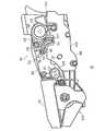
2.現像器接離機構
本実施形態のレーザプリンタ1には、感光ドラム99に対して現像カートリッジ34(詳しくは現像ローラ38)を接触/離間させるための現像器接離機構(本発明の「変位手段」に相当)が設けられている。図10はプロセスユニット21を他方の側壁47側から見た側面図であり、図11はプロセスユニット21の要部を前面側から見た正面図であり、図12,13は現像カートリッジ34を他方の側壁47側から見た側面図である。2. Developer Unit Contact / Separation Mechanism In the laser printer 1 of the present embodiment, a developer unit contact / separation mechanism (the “displacement means” of the present invention) for contacting / separating the developing cartridge 34 (specifically, the developing roller 38) with respect to the
この現像器接離機構は、現像カートリッジ34に設けられた現像器側接離機構部150と、本体フレーム2に設けられた本体側接離機構部166とから構成されており、現像器側接離機構部150は、図10に示すように、支持部材としての支持軸155と、係合体たるレバー156と、付勢部材としてのばね165とを備えている。 The developing device contact / separation mechanism includes a developing device side contact /
支持軸155は、図10及び図12に示すように、プロセス収容部104の前部の両側壁において、幅方向内側に向かって互いに対向するように突出状に設けられている。 As shown in FIGS. 10 and 12, the
レバー156は、各支持軸155に対応して、感光ドラム99の軸方向内側、より具体的には、プロセス収容部104の前部の両側壁において、それぞれ配置されている。各レバー156は、板体からなるレバー本体156aと、レバー本体156aの前側上部に形成される摘み部157と、レバー本体156aの上面中央から下方に向かって実質的にU字溝状に開口される第1受入部158と、レバー本体156aの前端部下方において、下方に向かって実質的にU字溝状に開口される第2受入部159と、レバー本体156aの前端部において、摘み部157と第2受入部159との間に形成され、後方斜め上方に向かって凹状に形成される形成されるばね受け部160と、レバー本体156aの下面前側において、傾斜状に形成される当接面161が一体に形成されている。
また、このレバー156の第1受入部158の開口部分には、係合軸162を誘い込むための傾斜面163が設けられている。The
Further, an
そして、このレバー156は、プロセス収容部104の支持軸155に、下方に向かって開口される第2受入部159を嵌合させることにより、支持軸155によって揺動可能に支持されている。この状態において、レバー156は、後述するように、現像ローラ38と感光ドラム99とを接触させる接触位置と、現像ローラ38と感光ドラム99とを離間させる離間位置との間で揺動可能となる。また、この状態において、レバー156の当接面161を含む下端部は、プロセス収容部104の切欠部164を介して下方と連通される。 The
また、ばね165は、プロセス収容部104の前端部の幅方向両側において、その一端部がプロセス収容部104の前壁に係止され、その他端部がばね受け部160に受けられている。 One end of the
これによって、レバー156は、常には、ばね165の付勢力によって、支持軸155を支点として、上側が後方に前側が前方に傾倒するように付勢されている。そのため、レバー156は、後述するように、常には、ばね165の付勢力によって、接触位置に位置するように付勢されている。 Accordingly, the
また、本体フレーム2には、図11に示すように、各レバー156を揺動させるための本体側接離機構部166を備えている。この本体側接離機構部166は、連結部材としての駆動軸167と、押圧部材及び移動部材としてのカム168と、クラッチ169と、現像カートリッジ34(詳しくは現像ローラ38)の位置検出用のセンサ(以下、位置センサという)170と、当接部材としてのリリース板171とを備えている。 Further, as shown in FIG. 11, the main body frame 2 includes a main body side contact /
駆動軸167は、図11及び図12に示すように、本体フレーム2に対して装着状態にあるドラムフレーム98の各レバー156と対向するように、駆動軸167にそれぞれ設けられている。各カム168は、駆動軸167に対して偏心する厚板体からなり、図13に示すように、レバー156の当接面161と当接する第1カム面172と、図12に示すように、レバー156の当接面161と当接しない第2カム面173とを備えている。 As shown in FIGS. 11 and 12, the
また、各カム168は、レバー156に対して同じ位相、すなわち、側面視において、第1カム面172と第2カム面173とが同じ位置となるように、駆動軸167に設けられている。これによって、各カム168は、駆動軸167の回転により、第1カム面172と第2カム面173が、同じタイミングで、各レバー156の当接面161に対して交互に対向して、カム168の第1カム面172がレバー156の当接面161に当接する押圧位置(第1位置)と、カム168の第2カム面173がレバー156の当接面161た対向して当接しない非押圧位置(第2位置)との間を、交互に繰り返して位置し、レバー156の当接面161と係脱するように回転される。 Further, each
クラッチ169は、図11に示すように、駆動軸167の軸方向一方側であって、軸支持部174よりも他方向外側に設けられている。このクラッチ169には、離間モータ202(図16参照)からの動力が入力され、その動力を、駆動軸167に対して伝達又は遮断する。このクラッチ169は、周知のばねクラッチからなり、オン状態において、離間モータ202からの動力を図示しないギヤトレインを介して駆動軸167へ伝達する。また、オフ状態において、離間モータ202からの動力の駆動軸167への伝達を遮断する。 As shown in FIG. 11, the clutch 169 is provided on one side in the axial direction of the
より具体的には、クラッチ169は、印刷動作時には、オン状態になり、離間モータ202からの動力を駆動軸167へ伝達し、カム168を回転させる。一方、印刷動作終了時やエラー発生時等、前カバー32を開位置に位置させてプロセスユニット21を取り出す必要のあるときには、オフ状態となり、離間モータ202からの動力の駆動軸167への伝達を遮断して、カム168のフリー状態を確保する。 More specifically, the clutch 169 is turned on during the printing operation, transmits the power from the
位置センサ170は、遮光板としてのセンサディスク175、発光部176及び受光部177を備えている。
センサディスク175は、クラッチ169よりも軸方向外側の、駆動軸167の軸方向一方側端部に設けられている。このセンサディスク175は、図14に示すように、円板状をなし、径方向外方に膨出する略扇状の遮光部178が一体成形されている。The
The
発光部176及び受光部177は、光センサとして構成され、センサディスク175の遮光部178を挟む位置において対向配置されている。これによって、センサディスク175の遮光部178は、発光部176と受光部177との間を駆動軸167の回転により、通過する。 The
この位置センサ170では、図14(a)に示すように、カム168の第1カム面172が、駆動軸167の回転駆動によってレバー156の当接面161への当接を開始するのに同期して、図14(b)に示すように、遮光部178が発光部176及び受光部177との間への進入を開始して、発光部176から受光部177へ向かう光を遮光する。また、図15(a)に示すように、カム168の第1カム面172が、駆動軸167の回転駆動によってレバー156の当接面161への当接を終了するのに同期して、図15(b)に示すように、遮光部178が発光部176と受光部177との間への進入を終了して、発光部176から受光部177へ向かう光を通過させるようになる。 In this
つまり、この位置センサ170では、カム168がレバー156を押圧する間、発光部176から受光部177へ向かう光が遮断され、カム168がレバー156を押圧しない間、発光部176から受光部177へ向かう光が通過される。これによって、カム168がレバー156を押圧する押圧位置にある状態か、カム168がレバー156を押圧しない非押圧位置にある状態かを検知している。 In other words, in this
そのため、この位置センサ170によるレバー156の押圧位置及び非押圧位置の検知により、現像ローラ38と、感光ドラム99との間の接触又は離間の状態を検知することができる。 Therefore, by detecting the pressed position and the non-pressed position of the
また、この位置センサ170では、発光部176から発光され受光部177において、受光された光が、遮光部178により遮光されたか否かにより、カム168の押圧位置及び非押圧位置を検知するので、確実な検知ができる。 The
そして、図10に示すように、現像カートリッジ34を、ドラムカートリッジ33のプロセス収容部104に、係合軸162を上方に向かって開口されている各レバー156の第1受入部158に上方から受け入れさせるようにして収納する。 Then, as shown in FIG. 10, the developing
このとき、現像カートリッジ34がドラムカートリッジ33のプロセス収容部104に収容された状態では、ばね165の付勢力によって、レバー156が支持軸155を支点として、その上側が後方に向かって押圧され接触位置に位置されるので、そのレバー156に係合している係合軸162が後方に配置される。その結果、図12に示すように、現像カートリッジ34がドラムカートリッジ33に対して後方に配置され、現像ローラ38と感光ドラム99とが接触する。 At this time, in a state where the developing
このようにして、本体収容部30に装着された現像カートリッジ34、つまりプロセスユニット21において、このレーザプリンタ1では、現像時、つまり、印刷動作時には、図12に示すように、カム168の第2カム面173がレバー156の当接面161に対向して、これらが互いに当接しない非押圧位置に位置されている。カム168が非押圧位置に位置されているときには、レバー156は、上述したように、ばね165の付勢力により接触位置に位置されるので、現像ローラ38と感光ドラム99とが接触する。 In this way, in the developing
一方、ウォーミングアップ動作時等、現像ローラ38と感光ドラム99とを離間させる必要があるときには、このレーザプリンタ1では、離間モータ202からの動力を駆動軸167に入力し、駆動軸167を回転させることにより、カム168の第1カム面172がレバー156の当接面161に対向して、これらが互いに当接する押圧位置に位置させる。すると、図13に示すように、カム168の第1カム面172がレバー156の当接面161を押圧するので、レバー156は、ばね165の付勢力に抗して、支持軸155を支点として、上側が前方に下側が後方に揺動されて、離間位置に位置される。レバー156が離間位置に位置されると、そのレバー156の第1受入部158に係合している係合軸162が、レバー156の揺動に伴って、前方に移動されるので、現像カートリッジ34がドラムカートリッジ33に対して前方に移動され、その結果、現像ローラ38が感光ドラム99から離間される。 On the other hand, when it is necessary to separate the developing
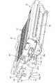
3.現像ローラに現像バイアス等を印加するための構成
図16はプロセスユニットを前方側から見た斜視図であり、図17は現像カートリッジを前方側から見た斜視図である。図10,16,17に示すように、現像ローラ38のローラ軸38aの軸端部は、導電性材料からなる軸受け部材230によって回転可能に軸支され、その軸受け部材230に対して上方に離間した位置に現像側電極231が設けられている。現像側電極231は他方の側壁47にネジ止めされ、後端部には本体フレーム2に設けられた現像側給電部材240と接触する接触部231aが突設されている。そして、本実施形態では、軸受け部材230と現像側電極231とがヒューズ素子232を介して電気的に接続されている。3. FIG. 16 is a perspective view of the process unit as viewed from the front side, and FIG. 17 is a perspective view of the development cartridge as viewed from the front side. As shown in FIGS. 10, 16, and 17, the shaft end portion of the
図18は、本体収容部30のうちプロセスユニット21の他方の側壁47と対向する内壁面30aを部分的に示した模式図である。同図に示すように、内壁面30aには開口31側に向けて幅広に開放した案内溝30bが窪み形成されている。この案内溝30bの最後部には、プロセスユニット21が装着完了した状態で感光ドラム99のローラ軸99aの軸端部と接触する、線バネからなるドラム側接地電極242が設けられている。 FIG. 18 is a schematic view partially showing an
また、案内溝30bの中央上方部には、プロセスユニット21が装着完了した状態で現像側電極231の接触部231aと接触する、線バネからなる現像側給電部材240が設けられている。更に、ドラム側接地電極242と現像側給電部材240との間には、プロセスユニット21が装着完了した状態で現像ローラ38のローラ軸38aの軸端部に接触/離間可能な、線バネからなる現像側接地電極243が設けられている。 In addition, a development-side
図12に示すように、現像カートリッジ34が接触位置にあるときは、現像側電極231は現像側給電部材240と接触しているが、現像側接地電極243は現像ローラ38のローラ軸38aから離間した状態になっている。一方、図13に示すように、現像カートリッジ34が離間位置にあるときは、現像側電極231と現像側給電部材240とはそのまま接触を維持し、現像ローラ38のローラ軸38aと現像側接地電極243とが接触するようになっている。 As shown in FIG. 12, when the developing
4.レーザプリンタの制御部
次に図19は、上記各部を制御するためにレーザプリンタ1に内蔵された制御装置180の構成を表すブロック図である。4). Next, FIG. 19 is a block diagram showing a configuration of a control device 180 built in the laser printer 1 for controlling the above-described units.
この制御装置180は、スキャナ部20、プロセスユニット21、定着部22からなる画像形成部5、レーザプリンタ1の用紙搬送系の動力源となるメインモータ200、現像器接離機構の動力源となる離間モータ202等を、操作部220を介して入力される使用者からの指令、もしくは、ネットワークを介して入力される各種情報処理装置(パーソナルコンピュータ等)からの指令に従い制御するためのものであり、CPU182、ROM184、RAM186、及び、これら各部を接続するバスライン188を中心とする周知のマイクロコンピュータにて構成されている。 The control device 180 serves as a power source for the
また、制御装置180には、CPU182からの指令に従い画像形成部5を制御するための画像形成制御部190、CPU182からの指令に従いメインモータ200及び離間モータ202をそれぞれ駆動するためのモータ駆動部191、192、CPU182からの指令に従い液晶表示装置等からなる表示部210に当該プリンタ1の動作状態等を表示するための表示制御部193、操作部220を介して入力される使用者からの指令信号や、上述した位置センサ170或いは新旧判別センサ115及びトナー切れ検出センサ196からの検出信号を制御装置180内に取り込むための信号入力部194、ネットワークを介して外部の情報処理装置(パーソナルコンピュータ等)との間でデータ通信を行うためのネットワークインターフェイス(ネットワークI/F)195も備えられており、これら各部は、バスライン188を介して、CPU182、ROM184、RAM186に接続されている。 The control device 180 includes an image
また、上記現像側給電部材240に現像バイアス電圧を印加するなど、各部にバイアス等を印加するためのバイアス印加回路198を制御する電力制御部199がバスライン188を介して、CPU182等に接続されている。この電力制御部19は、レーザプリンタ1の印刷動作時(現像カートリッジ34が接触位置にある時)には、バイアス印加回路198を電圧制御して現像側給電部材240及び軸受け部材230を介して現像ローラ38に現像バイアスを印加する。 Further, a
一方、電力制御部19レーザプリンタ1がウォーミングアップ動作時など非印刷動作時(現像カートリッジ34が離間位置にある時)において、現像カートリッジ34の寿命到来と判断された場合には、バイアス印加回路198を電流制御してヒューズ素子232を溶断可能な溶断電流を現像側給電部材240及び軸受け部材230を介して流し、この溶断電流は現像ローラ38と接触している現像側接地電極243を介してグランドに流れ込む。 On the other hand, when it is determined that the life of the developing
また、信号入力部194には、現像ローラ38の回転数をカウントする回転数センサ197からの検出信号も入力されるようになっている。 The
そして、CPU182は、外部の情報処理装置からネットワークを介してプリント要求を受けると、その後ネットワークを介して送信されてくるプリントデータに従い画像形成制御部190やメインモータ200を駆動制御することにより、用紙3を搬送しつつ用紙3上にプリントデータに基づく画像を形成する。 When the
また、CPU182は、用紙3への画像形成を確実に行うために、画像形成中には、用紙3の搬送経路上での紙詰まり(用紙ジャム)やトナー切れが発生していないかを判定し、用紙ジャムや上記トナー切れ検出センサ196によるトナー切れを検出すると、画像形成禁止エラーが発生したとして、画像形成手段としての画像形成部5の動作を停止させて、印刷動作を禁止する、画像形成禁止手段としての処理を実行する。 Further, the
また、CPU182は、用紙3への画像形成を行う際に、現像カートリッジ34(詳しくは現像ローラ38)が感光ドラム99から離間している場合には、現像器離間機構の動力源である離間モータ202を駆動して、感光ドラム99に対して現像カートリッジ34(詳しくは現像ローラ38)を接触させ、ウォーミングアップ時等、現像ローラ38と感光ドラム99とを離間させる必要があるときには、離間モータ202を駆動して、現像カートリッジ34(詳しくは現像ローラ38)を感光ドラム99から離間させる、現像カートリッジ34の接離制御を実行する。 Further, when the image is formed on the sheet 3, the
CPU182は、用紙3への画像形成のための制御(画像形成制御)を実行していないときに、離間モータ202をカム168の1回転分以上回転させ、その回転中に位置センサ170によって現像カートリッジ34の感光ドラム99からの離間が検出されたか否かを判断することにより、離間エラーが発生しているか否かを判断する、離間エラー検出処理を実行する。そして、現像器離間機構におけるカム168の破損若しくは位置センサ170の故障などにより、現像カートリッジ34の感光ドラム99からの離間を検知できない場合には、現像カートリッジ34が常に感光ドラム99に接触する離間エラーが発生していることが考えられる。ここで、CPU182は、この処理により離間エラーを検出した際にも、画像形成禁止エラーが発生したとして、画像形成部5による印刷動作を禁止するが、この状態で使用者が操作部220を介して画像形成継続指令を入力すると、画像形成部5による印刷動作を許可する。 The
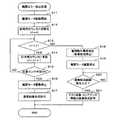
(1)離間エラー検出処理
以下、この離間エラー検出処理を、図20に示すフローチャートに沿って説明する。(1) Separation Error Detection Processing Hereinafter, this separation error detection processing will be described along the flowchart shown in FIG.
図20に示すように、この離間エラー検出処理では、まずS11(Sはステップを表す)にて、離間モータ202の駆動を開始し、続くS12にて、離間モータ202の駆動時間計時用のカウンタt1を値0に初期化する。 As shown in FIG. 20, in this separation error detection process, first, the drive of the
そして、続くS13では、そのカウンタt1の値(換言すれば離間モータ202の駆動時間)が、現像器離間機構のカム168を1回転させるのに要する時間を表す設定値T1よりも小さいか否かを判定し、t1<T1で、離間モータ202の駆動時間が設定値T1で決まる設定時間よりも短い場合には、S14に移行して、カウンタt1の値をインクリメントすることにより、離間モータ202の駆動時間を更新し、S15に移行する。 In subsequent S13, whether or not the value of the counter t1 (in other words, the driving time of the separation motor 202) is smaller than a set value T1 representing the time required to rotate the
S15では、位置センサ170により離間/接触の検出結果が反転したか否かを判断し、位置センサ170による検出結果が反転した場合には、感光ドラム99に対する現像カートリッジ34の離間/接触は正常になされているものと判断して、S16に移行する。そして、S16では、離間モータ202の駆動を停止し、続くS17にて、通常の印刷動作を許可した後、当該離間エラー検出処理を終了する。 In S15, it is determined whether the detection result of the separation / contact is reversed by the
一方、S15にて、位置センサ170による検出結果が反転していないと判断された場合には、再度、S13に移行して、カウンタt1の値が設定値T1よりも小さいか否かを判定する。そして、S13にて、カウンタt1の値が設定値T1以上となって、離間モータ202の駆動時間が設定値T1で決まる設定時間に達したと判断された場合には、S18に移行し、現像器離間機構による現像カートリッジ34の感光ドラム99からの離間動作に異常があるものとして、画像形成部5による印刷動作を禁止する、画像形成禁止手段としての処理を実行する。 On the other hand, when it is determined in S15 that the detection result by the
またこのようにS18にて印刷動作を禁止した後は、S19にて離間モータ202の駆動を停止した後、S20にて、使用者が操作部220に設けられた複数のキーの内、予め設定された画像形成継続指令入力用の複数のキーを所定の順で操作することにより、画像形成継続指令を入力したか否かを判断する。なお、本実施例では、このS20の判定処理が、本発明の判断手段として機能する。 In addition, after the printing operation is prohibited in S18 as described above, the driving of the
そして、S20にて、画像形成継続指令が入力されたと判断されると、S21に移行して、ROM184内に予め記憶されたテスト画像形成用のプリントデータに基づく画像形成、若しくは、RAM186内に記憶されている当該レーザプリンタ1の動作履歴や現在の状態を表すメンテナンス情報の画像形成を許可する、画像形成許可手段としての処理を実行し、当該離間エラー検出処理を終了する。 If it is determined in S20 that an image formation continuation command has been input, the process proceeds to S21, and image formation based on test image formation print data stored in advance in the
また次に、CPU182は、プロセスユニット21が本体収容部30に装着された際には、上述したウォーミングアップ動作を開始して、現像カートリッジ34が新品か旧品かを検出するが、その検出に用いられる新旧判別機構112が故障して、現像カートリッジ34の新旧を判別できなくなると、画像形成時に感光ドラム99に付着させるトナーの量を最適に制御できず、用紙3にきれいな画像を形成できないことがある。 Next, when the
そこで、本実施形態では、CPU182が新旧判別機構112を用いて現像カートリッジ34の新旧を識別する際、新旧判別機構112の故障を判定して、新旧判別機構112が故障している場合には、画像形成禁止エラーが発生したとして、画像形成部5による印刷動作を禁止するようにされている。 Therefore, in this embodiment, when the
そして、新旧判別機構112が故障した場合には、現像器離間機構の故障によって現像カートリッジ34の離間エラーが発生した場合と同様、画像形成部5による画像形成は実行可能であるため、CPU182は、新旧判別機構112の故障に伴い画像形成を禁止しているときに、使用者が操作部220を介して画像形成継続指令を入力すると、画像形成部5による印刷動作を許可するようにされている。 When the new /
(2)新旧判別処理
以下、このように、プロセスユニット21の本体収容部30への装着後にCPU182にて実行される現像カートリッジ34の新旧判別処理を、図21に示すフローチャートに沿って説明する。
なお、新旧判別機構112の故障としては、新旧判別センサ115の検知レバー115aの接点の故障、アクチュエータ113の破損等が考えられ、このような故障時には、新旧判別センサ115は現像カートリッジ34が常に新品であると検知してしまうことになる。(2) New / Old Discrimination Processing Hereinafter, the new / old discrimination processing of the developing
The failure of the new /
図21に示すように、現像カートリッジ34の新旧判別処理では、まずS31にて、メインモータ200の駆動を開始し、続くS32にて、メインモータ200の駆動時間計時用のカウンタt2を値0に初期化する。
そして、続くS33では、そのカウンタt2の値(換言すればメインモータ200の駆動時間)が、プロセスユニット21が本体収容部30へ装着されてから新旧判別機構112の当接部82が新品位置から旧品位置へと移動するのに要する時間よりも大きい判定時間を表す設定値T2よりも小さいか否かを判定する。As shown in FIG. 21, in the new / old discriminating process of the developing
In subsequent S33, the value of the counter t2 (in other words, the driving time of the main motor 200) is determined so that the
そして、t2<T2で、メインモータ200の駆動時間が設定値T2で決まる判定時間よりも短い場合には、S34に移行して、カウンタt2の値をインクリメントすることにより、メインモータ200の駆動時間を更新し、S35に移行する。 If t2 <T2 and the drive time of the
S35では、新旧判別センサ115による検出結果が正常であるか否かを判定する。つまり、今回装着された現像カートリッジ34が新品であれば、新旧判別センサ115による検出結果は新品から旧品へと変化し、今回装着された現像カートリッジ34が旧品であれば、新旧判別センサ115による検出結果は旧品であることから、S35では、新旧判別センサ115による検出結果が最初から旧品である場合には、新旧判別機構112は正常に動作しているものとして、S36に移行する。そして、S36では、メインモータ200の駆動を停止し、続くS37にて、通常の印刷動作を許可した後、当該新旧判別処理を終了する。 In S35, it is determined whether or not the detection result by the new /
一方、S35にて、新旧判別機構112が正常であると判断できない場合には、再度、S33に移行して、カウンタt2の値が設定値T2よりも小さいか否かを判定する。そして、S33にて、カウンタt2の値が設定値T2以上となって、メインモータ200の駆動時間が設定値T2で決まる判定時間に達したと判断された場合には、S38に移行し、新旧判別機構112が故障し、新旧検出エラーが発生したとして、画像形成部5による印刷動作を禁止する、画像形成禁止手段としての処理を実行する。 On the other hand, in S35, when it cannot be determined that the new /
またこのようにS38にて印刷動作を禁止した後は、S39にてメインモータ200の駆動を停止した後、S40にて、使用者が操作部220に設けられた複数のキーの内、予め設定された画像形成継続指令入力用の複数のキーを所定の順で操作することにより、画像形成継続指令を入力したか否かを判断する。なお、本実施例では、このS40の判定処理が、上述のS20と同様に本発明の判断手段として機能する。 In addition, after prohibiting the printing operation in S38 in this manner, the driving of the
そして、S40にて、画像形成継続指令が入力されたと判断されると、S41に移行して、ROM184内に予め記憶されたテスト画像形成用のプリントデータに基づく画像形成、若しくは、RAM186内に記憶されている当該レーザプリンタ1の動作履歴や現在の状態を表すメンテナンス情報の画像形成を許可する、画像形成許可手段としての処理を実行し、当該新旧判別処理を終了する。 If it is determined in S40 that an image formation continuation command has been input, the process proceeds to S41 and image formation based on test image formation print data stored in advance in the
(3)寿命判断処理と通電遮断動作
CPU182は、上記新旧判別処理で新品と判断した後、回転数センサ197からの検出信号に基づき現像ローラ38の回転回数をカウントしている。そして、このカウント回数が所定の限界数になったときに、現在装着されている現像カートリッジ34に寿命が到来したと判断する。なお、限界数は、例えば、1枚の用紙3につき5%の領域を印刷する動作を繰り返し行った場合、アジテータ36の攪拌によって新品のトナー剤の帯電性能が低下し、用紙3の適切な位置に転写されない、いわゆる印刷かぶりが生じるまでの現像ローラ38の回転回数としている。(3) Life determination process and energization cut-off operation The
また、CPU182は、トナー切れ検出センサ196からの検出信号によりトナー切れを検出したときにも現像カートリッジ34の寿命到来と判断する。そして、CPU182は、常には電力制御部199及びバイアス印加回路198によって現像ローラ38に現像バイアスを印加して印刷動作を実行する(図12参照)。一方、トナー切れ検出センサ196や回転数センサ197からの検出信号に基づき現像カートリッジ34の寿命到来と判断したときは、現像カートリッジ34が離間位置(図13参照)にあることを検出した後に、電力制御部199によりバイアス印加回路198から溶断電流を流してヒューズ素子232を溶断させる。即ち、本発明でいう「復帰不能な遮断動作」を実行するのである。 The
これにより、現像側電極231と軸受け部材230とは電気的に非接続となり、現像バイアスが現像ローラ38に印加されることはなくなる。従って、この寿命到来した現像カートリッジ34が同種の他のレーザプリンタ1に誤って装着されて、印刷動作が実行されてもトナーが転写されていない用紙3が排出されることになり、その再使用による画像劣化の発生を抑制できる。 As a result, the development-
なお、本実施形態では、CPU182は、トナー切れにより現像カートリッジ34の寿命到来と判断された後、或いはその前の所定枚数(例えば数枚程度)の用紙3の印刷について現像ローラ38の回転速度を下げて印刷動作を実行するようにメインモータ200を制御する機能も有している。これにより、現像ローラ38から感光ドラム99へのトナー供給量を下げることができるので、意図的に印刷かすれを発生させることができる。従って、前もってトナー切れであり正常に印刷動作ができないことをユーザに知らせることができる。 In the present embodiment, the
<実施形態2>
図22は実施形態2を示す。前記実施形態1との相違は、主として通電遮断手段を機械的スイッチ250とした点にあり、その他の点は前記実施形態1と同様である。従って、実施形態1と同一符号を付して重複する説明を省略し、異なるところのみを次に説明する。
図22に示すように、本実施形態の通電遮断手段は、軸受け部材230と現像側電極231との間に接続された機械的スイッチ250としている。
この構成によれば、この機械的スイッチ250は、軸受け部材230及び現像側電極231の間において非導電性箱体254内に収容されている。機械的スイッチ250は、軸受け部材230及び現像側電極231にそれぞれ連なる1対の接点251,251と、それら両接点251,251間を電気的に接続する接続部材252とを備えている。接続部材252は後方面に棒状の被押圧部材253が設けられ、この被押圧部材253は非導電性箱体254の後壁を貫く筒体255に挿通されている。
<Embodiment 2>
Figure 22shows theimplementation form 2. The difference from the first embodiment is that a
As shown in FIG. 22, the energization cut-off means of this embodiment is a
According to this configuration, the
一方、本体ケース2側には、上記筒体255内に進入して被押圧部材253を押圧することで接続部材252を両接点251,251から離間させる、押圧部材256が移動可能に設けられている。そして、上記現像カートリッジ34の寿命到来と判断されたときに押圧部材256が被押圧部材253を押圧して、本発明でいう復帰不能な遮断動作を実行するのである。 On the other hand, on the main body case 2 side, a pressing
このような構成であっても、一旦、非接続となった機械的スイッチ250は非導電性箱体254に覆われているため、容易に接続状態にすることができず、寿命が到来した現像カートリッジ34が再使用されたとしても劣化した画像の形成を抑制できる。 Even in such a configuration, the
<他の実施形態>
本発明は上記記述及び図面によって説明した実施形態に限定されるものではなく、例えば次のような実施形態も本発明の技術的範囲に含まれ、さらに、下記以外にも要旨を逸脱しない範囲内で種々変更して実施することができる。
(1)上記実施形態1では、ヒューズ素子232を遮断させるための溶断電流を現像側電極240を介して流す構成であったが、別途設けた専用電極によってヒューズ素子232に溶断電流を流す構成であってもよい。<Other embodiments>
The present invention is not limited to the embodiments described with reference to the above description and drawings. For example, the following embodiments are also included in the technical scope of the present invention, and further, within the scope not departing from the gist of the invention other than the following. Various modifications can be made.
(1) In the first embodiment, the fusing current for interrupting the
(2)実施形態2において、スイッチ手段は、逆電流が流されない限り、非接触状態を維持する、キープソレノイドスイッチで遮断動作させる構成であってもよい。 (2) In the second embodiment, the switch means may be configured to perform a shut-off operation with a keep solenoid switch that maintains a non-contact state unless a reverse current flows.
(3)上記実施形態1のヒューズ素子232による通電遮断の構成と、実施形態2の機械的スイッチ250による通電遮断の構成とを組み合わせたものであってもよい。 (3) The configuration of the energization cutoff by the
(4)上記各実施形態では、現像ローラ38の回転数に基づき現像カートリッジ34の寿命到来を判断したが、これに限らず、感光ドラム99の回転数に基づき上記寿命到来を判断するものであってもよい。 (4) In each of the above embodiments, the end of the life of the developing
1…レーザプリンタ(画像形成装置)
3…用紙(被記録媒体)
34…現像カートリッジ
38…現像ローラ(現像剤担持体)
40…トナー収容室(現像剤収容室)
99…感光ドラム(像担持体)
150…現像器側接離機構部(変位手段)
166…本体側接離機構部(変位手段)
180…制御装置(制御手段、実行手段、判断手段)
196…トナー切れ検出センサ(現像剤センサ)
197…回転数センサ
198…バイアス印加回路(印加手段)
231…現像側電極
232…ヒューズ素子(通電遮断手段)
243…現像側接地電極(接地電極)
250…機械的スイッチ(スイッチ手段)
256…押圧部材(アクチュエータ)1. Laser printer (image forming device)
3 ... paper (recording medium)
34 ... developing
40. Toner storage chamber (developer storage chamber)
99 ... Photosensitive drum (image carrier)
150... Developer side contact / separation mechanism (displacement means)
166 ... Main body side contact / separation mechanism (displacement means)
180... Control device (control means, execution means, judgment means)
196: Toner out detection sensor (developer sensor)
197 ...
231...
243 ... Development-side ground electrode (ground electrode)
250 ... Mechanical switch (switch means)
256 ... Pressing member (actuator)
Claims (5)
Translated fromJapanese前記現像カートリッジは、
現像剤を収容する現像剤収容室と、
現像バイアスが印加される現像側電極と、
前記現像側電極に印加された現像バイアスを受けることで前記現像剤収容室内の現像剤を像担持体に供給する現像剤担持体と、
前記現像側電極と前記現像剤担持体との間を電気的に接続するヒューズ素子と、
前記像担持体と前記現像剤担持体とを接離可能に変位させる変位手段と、
前記像担持体と前記現像剤担持体とが離間した状態で当該現像剤担持体と接触する接地電極と、を有し、
前記画像形成装置本体は、
前記現像カートリッジの寿命到来か否かを判断する判断手段と、
前記現像側電極に前記現像バイアスを印加する印加手段と、
前記変位手段を制御して、画像形成動作時に前記像担持体と前記現像剤担持体とを接触させる一方で、非画像形成動作時に前記像担持体と前記現像剤担持体とを離間させる制御手段と、
前記判断手段で前記寿命到来と判断された場合に、前記非画像形成動作時に前記ヒューズ素子に溶断電流を流して前記現像側電極と前記現像剤担持体との間の通電を遮断する実行手段と、を有することを特徴とする画像形成装置。An image forming apparatus comprising: an image forming apparatus main body; and a developing cartridge that is detachably attached to the image forming apparatus main body.
The developing cartridge is
A developer storage chamber for storing the developer;
A development side electrode to which a development bias is applied;
A developer carrier that supplies the developer in the developer storage chamber to the image carrier by receiving a development bias applied to the development side electrode;
A fuse element for electrically connecting between the development side electrode and the developer carrying member;
A displacement means for displacing the image carrier and the developer carrier so as to be capable of contacting and separating;
A ground electrode in contact with the developer carrier in a state where the image carrier and the developer carrier are separated from each other ;
The image forming apparatus main body includes:
Determining means for determining whether the life of the developing cartridge is reached;
Applying means for applying the developing bias to the developing-side electrode;
Control means for controlling the displacement means to bring the image carrier and the developer carrier into contact with each other during an image forming operation, while separating the image carrier from the developer carrier during a non-image forming operation. When,
Execution meansfor cutting off the energization between the development side electrode and the developer carrying member by causing a fusing current to flow through the fuse element during the non-image forming operation when the determination means determines that the lifetime has come; And an image forming apparatus.
前記現像カートリッジは、
現像剤を収容する現像剤収容室と、
現像バイアスが印加される現像側電極と、
前記現像側電極に印加された現像バイアスを受けることで前記現像剤収容室内の現像剤を像担持体に供給する現像剤担持体と、
前記現像側電極と前記現像剤担持体との間を電気的に接続し、復帰不能な遮断動作によって両者間の通電を遮断する通電遮断手段と、を有し、
前記画像形成装置本体は、
前記現像カートリッジの寿命到来か否かを判断する判断手段と、
前記現像側電極に前記現像バイアスを印加する印加手段と、
前記判断手段で前記寿命到来と判断された場合に、前記通電遮断手段に前記遮断動作を実行させる実行手段と、を有し、
前記通電遮断手段は、前記現像側電極と前記現像剤担持体との間を開閉可能に接続するスイッチ手段であり、
前記実行手段は、前記スイッチ手段に開動作させるアクチュエータであることを特徴とする画像形成装置。An image forming apparatus comprising: an image forming apparatus main body; and a developing cartridge that is detachably attached to the image forming apparatus main body.
The developing cartridge is
A developer storage chamber for storing the developer;
A development side electrode to which a development bias is applied;
A developer carrier that supplies the developer in the developer storage chamber to the image carrier by receiving a development bias applied to the development side electrode;
A current-carrying means for electrically connecting between the development-side electrode and the developer-carrying member, and shutting off power supply between the two by a non-recoverable cut-off operation;
The image forming apparatus main body includes:
Determining means for determining whether the life of the developing cartridge is reached;
Applying means for applying the developing bias to the developing-side electrode;
Execution means for causing the energization interruption means to execute the interruption operation when the determination means determines that the lifetime has come;
The energization cut-off means is a switch means for connecting the development side electrode and the developer carrying member so as to be openable and closable,
The image forming apparatus, wherein the execution unit is an actuator that causes the switch unit to open.
前記判断手段は、前記現像ローラ又は当該現像ローラの回転に伴って回転する前記像担持体としての感光ドラムの回転数をカウントする回転数センサを有し、当該回転数センサにおけるカウント回転数が限界数に達した場合に前記寿命到来と判断することを特徴とする請求項1〜請求項3のいずれかに記載の画像形成装置。The developer carrier is a developing roller that rotates and supplies the developer to the image carrier,
The determination means includes a rotation speed sensor that counts the rotation speed of the developing roller or the photosensitive drum as the image carrier that rotates as the development roller rotates, and the count rotation speed of the rotation speed sensor is limited. the image forming apparatus according to any one of claims 1 to3, characterized in that it is determined that the lifetime arrives at when reaching the number.
Priority Applications (2)
| Application Number | Priority Date | Filing Date | Title |
|---|---|---|---|
| JP2005013179AJP4247747B2 (en) | 2005-01-20 | 2005-01-20 | Image forming apparatus and developing cartridge |
| US11/335,517US7444087B2 (en) | 2005-01-20 | 2006-01-20 | Image forming apparatus and developer cartridge with power supply shielding mechanism |
Applications Claiming Priority (1)
| Application Number | Priority Date | Filing Date | Title |
|---|---|---|---|
| JP2005013179AJP4247747B2 (en) | 2005-01-20 | 2005-01-20 | Image forming apparatus and developing cartridge |
Publications (2)
| Publication Number | Publication Date |
|---|---|
| JP2006201493A JP2006201493A (en) | 2006-08-03 |
| JP4247747B2true JP4247747B2 (en) | 2009-04-02 |
Family
ID=36780065
Family Applications (1)
| Application Number | Title | Priority Date | Filing Date |
|---|---|---|---|
| JP2005013179AExpired - Fee RelatedJP4247747B2 (en) | 2005-01-20 | 2005-01-20 | Image forming apparatus and developing cartridge |
Country Status (2)
| Country | Link |
|---|---|
| US (1) | US7444087B2 (en) |
| JP (1) | JP4247747B2 (en) |
Families Citing this family (23)
| Publication number | Priority date | Publication date | Assignee | Title |
|---|---|---|---|---|
| US20080124122A1 (en)* | 2005-01-25 | 2008-05-29 | Pater Zhang | Resiliently Biased Developing Cartridge |
| USD566169S1 (en)* | 2005-07-12 | 2008-04-08 | Brother Industries, Ltd. | Toner cartridge |
| CA113953S (en)* | 2005-07-12 | 2007-05-03 | Brother Ind Ltd | Toner cartridge |
| USD550764S1 (en)* | 2005-12-22 | 2007-09-11 | Brother Industries, Ltd. | Toner cartridge |
| JP4591474B2 (en)* | 2007-04-20 | 2010-12-01 | 富士ゼロックス株式会社 | Method for regenerating developer container |
| JP2008281802A (en)* | 2007-05-11 | 2008-11-20 | Murata Mach Ltd | Image forming apparatus and recording material cartridge |
| JP4561846B2 (en) | 2008-02-29 | 2010-10-13 | ブラザー工業株式会社 | Image forming apparatus |
| JP4539736B2 (en) | 2008-02-29 | 2010-09-08 | ブラザー工業株式会社 | Tandem type photoreceptor unit and image forming apparatus |
| JP5317755B2 (en) | 2008-03-10 | 2013-10-16 | キヤノン株式会社 | Image forming apparatus |
| CA129686S (en)* | 2008-09-30 | 2009-11-16 | Brother Ind Ltd | Toner cartridge |
| USD638051S1 (en)* | 2008-09-30 | 2011-05-17 | Brother Industries, Ltd. | Toner cartridge |
| USD638055S1 (en)* | 2008-09-30 | 2011-05-17 | Brother Industries, Ltd. | Toner cartridge |
| USD638054S1 (en)* | 2008-09-30 | 2011-05-17 | Brother Industries, Ltd. | Toner cartridge |
| JP5511440B2 (en)* | 2009-06-12 | 2014-06-04 | キヤノン株式会社 | Image forming apparatus |
| JP5029682B2 (en)* | 2009-12-25 | 2012-09-19 | ブラザー工業株式会社 | Developer cartridge |
| JP5682183B2 (en)* | 2010-09-01 | 2015-03-11 | ブラザー工業株式会社 | Printing device |
| JP5206776B2 (en)* | 2010-11-30 | 2013-06-12 | ブラザー工業株式会社 | cartridge |
| JP5778933B2 (en) | 2011-01-28 | 2015-09-16 | キヤノン株式会社 | Printing apparatus, printing apparatus control method, and program |
| US8494380B2 (en)* | 2011-03-25 | 2013-07-23 | Brother Kogyo Kabushiki Kaisha | Developer storage unit and method for manufacturing recycling product |
| JP6156056B2 (en)* | 2013-10-25 | 2017-07-05 | ブラザー工業株式会社 | Image forming apparatus |
| JP7009145B2 (en)* | 2017-09-29 | 2022-01-25 | キヤノン株式会社 | Image forming device |
| JP7435131B2 (en)* | 2019-09-27 | 2024-02-21 | ブラザー工業株式会社 | Image forming device |
| JP7562979B2 (en)* | 2020-04-01 | 2024-10-08 | ブラザー工業株式会社 | Drum unit and image forming apparatus |
Family Cites Families (16)
| Publication number | Priority date | Publication date | Assignee | Title |
|---|---|---|---|---|
| JPH01263662A (en)* | 1988-04-15 | 1989-10-20 | Fuji Xerox Co Ltd | Recording device and its consumable component |
| US4956668A (en)* | 1988-07-05 | 1990-09-11 | Eastman Kodak Company | Developer mix monitoring for replaceable developer stations |
| JPH03225381A (en) | 1990-01-31 | 1991-10-04 | Fuji Xerox Co Ltd | Used/new toner cartridge judging device |
| JPH03230182A (en) | 1990-02-06 | 1991-10-14 | Canon Inc | Developing device and developer container |
| JP2937392B2 (en)* | 1990-03-22 | 1999-08-23 | 株式会社東芝 | Image forming device |
| JP3318139B2 (en)* | 1994-12-20 | 2002-08-26 | 株式会社リコー | Developing device |
| US5699091A (en)* | 1994-12-22 | 1997-12-16 | Hewlett-Packard Company | Replaceable part with integral memory for usage, calibration and other data |
| JP3379262B2 (en) | 1995-02-20 | 2003-02-24 | 松下電器産業株式会社 | One-component developing device |
| US5758224A (en)* | 1996-09-23 | 1998-05-26 | Hewlett-Packard Company | Fusable life indicator and identification device for an electrophotographic consumable product |
| JPH11258968A (en)* | 1998-03-13 | 1999-09-24 | Canon Inc | Image forming device |
| KR20000019760A (en)* | 1998-09-15 | 2000-04-15 | 윤종용 | Sensing device for replacing state of developer |
| JP2000293024A (en) | 1999-04-06 | 2000-10-20 | Matsushita Graphic Communication Systems Inc | Toner cartridge and recording device using toner cartridge |
| JP3848056B2 (en) | 2000-05-26 | 2006-11-22 | シャープ株式会社 | Image forming apparatus |
| US6647213B2 (en)* | 2001-11-30 | 2003-11-11 | Kabushiki Kaisha Toshiba | Image forming apparatus having a mode in which a process unit may be replaced |
| US7139492B2 (en)* | 2001-12-11 | 2006-11-21 | Toshiba Tec Kabushiki Kaisha | Imaging forming apparatus having a plurality of dismountable units necessary for image forming |
| JP2004029396A (en)* | 2002-06-26 | 2004-01-29 | Brother Ind Ltd | Image forming device |
- 2005
- 2005-01-20JPJP2005013179Apatent/JP4247747B2/ennot_activeExpired - Fee Related
- 2006
- 2006-01-20USUS11/335,517patent/US7444087B2/ennot_activeExpired - Fee Related
Also Published As
| Publication number | Publication date |
|---|---|
| US20060177230A1 (en) | 2006-08-10 |
| JP2006201493A (en) | 2006-08-03 |
| US7444087B2 (en) | 2008-10-28 |
Similar Documents
| Publication | Publication Date | Title |
|---|---|---|
| JP4247747B2 (en) | Image forming apparatus and developing cartridge | |
| JP4320571B2 (en) | Developing cartridge, process device, and image forming apparatus | |
| JP4353025B2 (en) | Image forming apparatus and program | |
| US11592781B2 (en) | Image forming apparatus having toner replenishment container control | |
| JP4665928B2 (en) | Cartridge and image forming apparatus | |
| US7995931B2 (en) | Image forming apparatus | |
| US11886141B2 (en) | Image forming apparatus having a toner replenishment operation | |
| JP6819639B2 (en) | How to remove restrictions on attachment / detachment of image forming equipment and developer housing | |
| JP2007199514A (en) | Image forming apparatus | |
| JP2007233072A (en) | Image forming apparatus | |
| US11644778B2 (en) | Image forming apparatus and control method thereof | |
| JP5051284B2 (en) | Image forming apparatus | |
| JP2006267806A (en) | Image forming apparatus | |
| JP4289076B2 (en) | Image forming apparatus | |
| JP2001109340A (en) | Method, device and system for detecting life of cartridge, and cartridge and storage medium | |
| US20140044445A1 (en) | Image forming apparatus | |
| JP7553373B2 (en) | Image forming device | |
| US20220082962A1 (en) | Image forming apparatus | |
| CN101661264B (en) | Processing unit and image forming apparatus | |
| JP2024155669A (en) | Image forming device |
Legal Events
| Date | Code | Title | Description |
|---|---|---|---|
| A131 | Notification of reasons for refusal | Free format text:JAPANESE INTERMEDIATE CODE: A131 Effective date:20081030 | |
| A521 | Request for written amendment filed | Free format text:JAPANESE INTERMEDIATE CODE: A523 Effective date:20081208 | |
| TRDD | Decision of grant or rejection written | ||
| A01 | Written decision to grant a patent or to grant a registration (utility model) | Free format text:JAPANESE INTERMEDIATE CODE: A01 Effective date:20081222 | |
| A01 | Written decision to grant a patent or to grant a registration (utility model) | Free format text:JAPANESE INTERMEDIATE CODE: A01 | |
| A61 | First payment of annual fees (during grant procedure) | Free format text:JAPANESE INTERMEDIATE CODE: A61 Effective date:20090104 | |
| FPAY | Renewal fee payment (event date is renewal date of database) | Free format text:PAYMENT UNTIL: 20120123 Year of fee payment:3 | |
| R150 | Certificate of patent or registration of utility model | Ref document number:4247747 Country of ref document:JP Free format text:JAPANESE INTERMEDIATE CODE: R150 Free format text:JAPANESE INTERMEDIATE CODE: R150 | |
| FPAY | Renewal fee payment (event date is renewal date of database) | Free format text:PAYMENT UNTIL: 20120123 Year of fee payment:3 | |
| FPAY | Renewal fee payment (event date is renewal date of database) | Free format text:PAYMENT UNTIL: 20130123 Year of fee payment:4 | |
| FPAY | Renewal fee payment (event date is renewal date of database) | Free format text:PAYMENT UNTIL: 20140123 Year of fee payment:5 | |
| LAPS | Cancellation because of no payment of annual fees |