JP4246878B2 - Laser repair method - Google Patents
Laser repair methodDownload PDFInfo
- Publication number
- JP4246878B2 JP4246878B2JP2000097116AJP2000097116AJP4246878B2JP 4246878 B2JP4246878 B2JP 4246878B2JP 2000097116 AJP2000097116 AJP 2000097116AJP 2000097116 AJP2000097116 AJP 2000097116AJP 4246878 B2JP4246878 B2JP 4246878B2
- Authority
- JP
- Japan
- Prior art keywords
- laser
- defect
- repair method
- opening
- opening defect
- Prior art date
- Legal status (The legal status is an assumption and is not a legal conclusion. Google has not performed a legal analysis and makes no representation as to the accuracy of the status listed.)
- Expired - Fee Related
Links
Images


Classifications
- Y—GENERAL TAGGING OF NEW TECHNOLOGICAL DEVELOPMENTS; GENERAL TAGGING OF CROSS-SECTIONAL TECHNOLOGIES SPANNING OVER SEVERAL SECTIONS OF THE IPC; TECHNICAL SUBJECTS COVERED BY FORMER USPC CROSS-REFERENCE ART COLLECTIONS [XRACs] AND DIGESTS
- Y02—TECHNOLOGIES OR APPLICATIONS FOR MITIGATION OR ADAPTATION AGAINST CLIMATE CHANGE
- Y02E—REDUCTION OF GREENHOUSE GAS [GHG] EMISSIONS, RELATED TO ENERGY GENERATION, TRANSMISSION OR DISTRIBUTION
- Y02E30/00—Energy generation of nuclear origin
- Y02E30/30—Nuclear fission reactors
Landscapes
- Laser Beam Processing (AREA)
Description
Translated fromJapanese【0001】
【発明の属する技術分野】
本発明は、例えば、原子炉の構造物などの基材に欠陥が発生した場合の健全性回復のためのメンテナンスに用いられるレーザ光を用いたレーザ補修方法に関するものである。
【0002】
【従来の技術】
従来、原子炉の構造物などの基材に欠陥が発生したような場合、欠陥を発生した機器全体を交換するか、あるいは、欠陥を発生した構造物に補強材などを設置して欠陥部を補強する方法などがとられていた。
【0003】
しかしながら、既設の原子炉の場合には、長期間の運転により中性子の照射を受け構造物全体が劣化している可能性があるため、特に、欠陥を発生した構造物に補強材などを設置する方法には、十分な注意が必要であった。
【0004】
また、このような原子炉の構造物の欠陥は、できるだけ早期に補修することが必要で、欠陥を完全に除去したのちに補修を行うことが望ましく、また、このような構造物の欠陥は、環境雰囲気と隔離させることが最低限の条件でもあるため、構造健全性確保が確認できれば構造物表面の開口欠陥の封止も有効な手段となる。
【0005】
そこで、従来、構造物などの基材の欠陥自体の補修方法として、TIG溶接などを用いたレーザ補修方法が考えられている。
【0006】
【発明が解決しようとする課題】
ところが、このようなTIG溶接方法を採用したレーザ補修方法によると、原子炉の長期間の運転により中性子の照射を受け構造物全体が劣化している可能性のある基材に対してTIG溶接が行われると、入熱が多いため再度欠陥が発生するおそれがある。また、TIG溶接方法は、基本的に基材とトーチ電極との間にアークを発生させながら基材を溶融する方法であるため、基材に酸化物が付着していたり、欠陥の隙間に酸化物が付着していたり、欠陥の隙間に水が入っていたり、あるいは、ギャップが大きく空いているように場合は、アークが発生せず安定した溶接を行うことができないという問題があった。
【0007】
本発明は、上記事情に鑑みてなされたもので、確実な欠陥補修を安定して行うことができるレーザ補修方法を提供することにある.
【0008】
【課題を解決するための手段】
請求項1記載の発明は、材料表面に開口した開口欠陥を除去して拡張欠陥部を形成した後、該拡張欠陥部と同一形状の埋め込み材をはめ込むとともに、該埋め込み材の周囲をレーザ溶接して前記開口欠陥内部の残留を許容して前記開口欠陥表面を前記埋め込み材により封止することを特徴としている。
このようにすれば、欠陥削除を行った後に完全に埋め戻しを行い完全な補修が可能で、かつ、補修部とその周辺の健全性も十分に向上させることができる。
【0009】
このようにすれば、レ−ザ補修により同時に脱鋭敏化が行われるため、補修域とその周辺の健全性(特に応力腐食割れに対する)を向上させることができる。
【0028】
請求項2記載の発明において、材料表面に開口した開口欠陥を除去して拡張欠陥部を形成した後、該拡張欠陥部と同一形状の埋め込み材をはめ込むとともに、該埋め込み材の表面に溶化材を用いてレーザ肉盛溶接して前記開口欠陥内部の残留を許容して前記開口欠陥表面を前記埋め込み材及びレーザ肉盛溶接により封止することを特徴としている。
【0029】
このようにしても、欠陥削除を行った後に完全に埋め戻しを行い完全な補修が可能で、かつ、補修部とその周辺の健全性も十分向上させることができる。
【0030】
請求項3記載の発明は、材料表面に開口した開口欠陥を除去して拡張欠陥部を形成した後、該拡張欠陥部と同一形状の埋め込み材をはめ込むとともに、該埋め込み材の上から当て板をレーザシーム溶接して前記開口欠陥内部の残留を許容して前記開口欠陥表面を前記埋め込み材及び当て板により封止することを特徴としている。
【0031】
このようにしても、欠陥削除を行った後に完全に埋め戻しを行い完全な補修が可能で、かつ、補修部とその周辺の健全性も十分向上させることができる。
【0036】
請求項4記載の発明は、請求項1乃至3のいずれかに記載の発明において、レーザ補修部およびその熱影響部に対してピーニングをおこない、材料表面に圧縮残留応力を付与することを特徴としている。
【0037】
このようにすれば、溶融したことにより発生した引張残留応力を圧縮残留応力に改善することができ、開口欠陥が多少残っていても新たに開口するようなことを防止できる。
【0040】
請求項5記載の発明は、材料表面に開口した開口欠陥に対し集光されたレーザ光の位置に高耐食性材料のフィーラワイヤを供給するとともに、アルゴンガス、ヘリウムガスあるいは窒素ガスを前記レーザ光と同軸に流すことにより、溶融された前記溶化材を飛散させ、前記開口欠陥内部の残留を許容して前記開口欠陥表面に前記飛散した高耐食性材料の付着金属層を形成して封止することを特徴としている。
【0041】
このようにすれば、いわゆるレーザ溶射により形成される付着金属層により、開口欠陥を封止することができる。
【0042】
請求項6記載の発明は、請求項5に記載の発明において、開口欠陥を除去して拡張欠陥部を形成した後、該拡張欠陥部に対して前記飛散された高耐食性材料を付着、積層させることを特徴としている。
【0043】
このようにすれば、欠陥削除を行った後に埋め戻しを行った状態から、わゆるレーザ溶射により形成される付着金属層により、開口欠陥を封止することができる。
【0044】
請求項7記載の発明は、請求項5または6に記載の発明において、前記付着された高耐食性材料にレーザ光を照射することにより再溶融することを特徴としている。
【0045】
このようにすれば、開口欠陥が新たに開口するようなことを確実に防止することができる。
【0046】
請求項8記載の発明は、請求項1乃至7のいずれかに記載の発明を原子力プラントまたは核融合炉機器の欠陥を対象させることを特徴としている。
【0047】
このようにすれば、原子力プラントまたは核融合炉機器の応力腐食割れ、疲労、Heバブル割れなどの欠陥やピットなどの欠陥の補修を行うことができる。
【0050】
【発明の実施の形態】
以下、本発明の実施の形態を図面に従い説明する。
【0051】
(第1の実施の形態)
図1は、本発明のレーザ補修方法が適用されるレーザ発生装置の概略構成を示している。図において、1は、レーザ発振器で、このレーザ発振器1には、光ファイバ2が接続され、レーザ発振器1から発せられるレーザ光を所定の位置まで導光するようにしている。また、光ファイバ2の先端には、集光レンズ3が配置され、この光ファイバ2の先端から出射されるレーザ光4を集光レンズ3を介して集光し、補修対象5に照射するようにしている。
【0052】
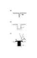
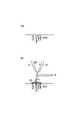
次に、このようなレーザ発生装置を使用して欠陥補修を行うレーザ補修方法について図2(a)(b)により説明する。
【0053】
この場合、補修対象5として、同図(a)に示すようなオーステナイト系ステンレス鋼501の組織が、Cr炭化物が結晶粒界に析出している鋭敏化組織502に変化し、その組織に引張応力がかかり微細な開口や深い開口を有する開口欠陥503が発生している例を示している。
【0054】
そして、このようなオーステナイト系ステンレス鋼501の開口欠陥503に対してレーザ発振器1から発せられるレーザ光4を光ファイバ2を介し集光レンズ3で集光して開口欠陥503に沿って走査しながら照射する。この場合、レーザ発振器1からのレーザ光4として、スポット径が約3mm、出力900W、速度0.8m/minのものを使用すると、オーステナイト系ステンレス鋼501に照射されることにより、同図(b)に示すように、開口欠陥503には、溶融層505として、深さが0.3mm、溶体化層504も含めると約0.55mmの組織改善層が得られた。そして、このような条件で溶融層505を重ねていき、開口欠陥503の表層部を封止することにより、オーステナイト系ステンレス鋼501の鋭敏化組織は、溶融層505と溶体化層504を含む健全な組織に改善することができた。
【0055】
なお、このようなレーザ補修方法でのレーザ光4の走査方法は、走査方向に対して直角に微小振動させてオーステナイト系ステンレス鋼501表面を溶融することも可能である。また、例えば、レーザ光4の径を0.5mmに集光し、その集光ビームを走査方向に対して振幅5mmで周波数20Hzでスキャンしながら表面を溶融することで同様な効果が得られた。
【0056】
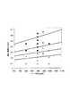
図3は、第1の実施の形態で用いられるレーザ光4による補修条件、つまり、レーザ照射条件を示している。この場合、図3に示すグラフは、鋭敏化したオーステナイト系ステンレス鋼501に照射されるレーザ光4の施工速度とレーザ出力を変化したときに再鋭敏化組織が発生するかしないかを実験的にもとめたデータで、グラフ中の黒丸は、再鋭敏化なし、白丸は、再鋭敏化ありで、また、直線aは、入熱量が1KJ/cmの場合、直線bは、1.5KJ/cmの場合、直線cは、2KJ/cmの場合、直線dは、2KJ/cmの場合をそれぞれ示している。そして、このグラフから、再鋭敏化が発生する条件は、約2KJ/cm以上であることが明らかであるから、上述したレーザ補修方法の限界は、2KJ/cm以下で施工することが必要となる。
【0057】
このようにすれば、開口欠陥503に対してレーザ光4により表面を溶融および溶体化層を形成することで、開口欠陥503を封止できるとともに、材質の改善を図ることもできる。
【0058】
(第2の実施の形態)
この第2の実施の形態のレーザ補修方法は、材料表面に開口した微小な割れやピッテイングなどの開口欠陥が発生した場合には、レーザ光を走査させずに静止させて加熱し、開口欠陥の表面または、全てを溶融し、開口欠陥を封止することを特徴としている。
【0059】
図4(a)(b)は、本発明の第2の実施の形態のレーザ補修方法を示すものである。なお、第2の実施の形態のレーザ補修方法が適用されるレーザ発生装置の概略構成は、図1と同様なので、同図を援用するものとする。
【0060】
この場合、図4(a)に示すように直径0.5mmの穴の開口欠陥503に対してビーム径3mm、レーザ出力1000Wのレーザ光4を走査させずに静止した状態で3秒間照射するようにした。
【0061】
このようにしても、同図(b)に示すように開口欠陥503の入口を溶融(約0.5mm)し、溶融層505により封止することができた。勿論、この場合、溶融層505の下部に溶体化層が存在することは自明である。
【0062】
(第3の実施の形態)
この第3の実施の形態のレーザ補修方法は、第2の実施の形態で述べたレーザ光を静止させて加熱するプロセスを連続して補修することを特徴としている。
【0063】
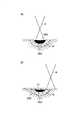
図5(a)(b)(c)は、本発明の第3の実施の形態のレーザ補修方法を示すものである。なお、第3の実施の形態のレーザ補修方法が適用されるレーザ発生装置の概略構成は、図1と同様なので、同図を援用するものとする。
【0064】
この場合、図5(a)に示すように穴のような開口欠陥503が基材に存在し、且つその中に水分などの内在物6が含まれているような場合、同図(b)に示すように第2の実施の形態で述べた条件で繰り返しレーザ光4を照射し、水分を蒸発させて気化物7として除去した後、さらに、レーザ光4を走査させずに静止した状態で照射することで、同図(c)に示すように溶融層505により開口欠陥503の穴を封止するようにしている。
【0065】
このようにすれば、開口欠陥503の内部にふくまれた内在物6を気化させながら封止することができる。
【0066】
(第4の実施の形態)
この第4の実施の形態のレーザ補修方法は、封止部のくぼみを平坦化するため、レ−ザ照射時の溶融部に溶化材を供給することを特徴としている。
【0067】
図6(a)(b)は、本発明の第4の実施の形態のレーザ補修方法を示すものである。なお、第4の実施の形態のレーザ補修方法が適用されるレーザ発生装置の概略構成は、図1と同様なので、同図を援用するものとする。
【0068】
この場合、図6(a)に示すように開口欠陥503の表面からレーザ光4を照射しつつ、溶化材8(あるいはフィラーワイヤ)を供給しながら開口欠陥503の表面層に肉盛溶接部9を形成し、開口欠陥503を残したままあるいは、完全に封止するかあるいは開口欠陥503の下部を残したまま封止するレーザ補修を行うようにしている。
【0069】
具体的には、レーザ光4の出力を1000Wとし照射時間を3秒、スポット径を3mmとし溶化材(0.6mm直径)8を1m/minの速度で2秒間供給することにより同図(b)に示すように深さ0.8mm(基材表面から0,3mmは盛り上がった)のレーザ肉盛溶融部9を形成することができた。これにより、深さ1mm、直径0.5mm程度の開口欠陥503は、0,5mmだけ残した状態で封止することができた。このようなレーザ補修方法によりピンホールや開口欠陥などを封止することが可能であることがわかった。
【0070】
(第5の実施の形態)
この第5の実施の形態のレーザ補修方法は、レ−ザ補修溶接により開口欠陥を封止後、表面にくぼみが生じるような場合に同一箇所に溶化材を用いてレ−ザ溶融し表面のくぼみを埋めることを特徴としている。
【0071】
図7(a)(b)は、本発明の第5の実施の形態のレーザ補修方法を示すものである。なお、第5の実施の形態のレーザ補修方法が適用されるレーザ発生装置の概略構成は、図1と同様なので、同図を援用するものとする。
【0072】
この場合、図7(a)に示すように直径0.5mmの穴の開口欠陥503に対してビーム径3mm、レーザ出力1000Wのレーザ光4を走査させずに静止した状態で3秒間照射することにより開口欠陥503の入り口を溶融層505(約0.5mm)により封止している。勿論、溶融層505の下部に溶体化層が存在することは自明である。
【0073】
しかし、このままでは、開口欠陥503を埋めるための溶融金属が足らずに表面にへこみが発生することがある。そこで、この溶融のみの封止法の後に同図(b)に示すように溶化材8を供給しながら封止を行った。この時のレーザ照射条件は、ビーム径3mm、レーザ出力1000Wのレーザ光4を使用し、このレーザ光4を走査させずに静止した状態で2秒間照射するとともに、溶化材(0.6mm直径)8を1m/minの速度で2秒間供給することにより、深さ0.8mm(基材表面から0.3mmは盛り上がった)の若干表面から盛り上がったレーザ肉盛溶融部9を形成することができた。
【0074】
このようにしても、深さ1mm、直径0.5mmの開口欠陥503を0.5mmだけ残した状態で封止することができた。このようなレーザ補修方法によってもピンホールや開口欠陥などを封止することが可能であることがわかった。
【0075】
(第6の実施の形態)
この第6の実施の形態のレ−ザ補修方法は、長い開口欠陥があるような場合に上述したレ−ザ補修方法で形成される溶接部の一部をラップするようにして開口欠陥に沿って補修位置を移動させながら補修を繰返することにより開口欠陥を封止することを特徴としている。
【0076】
図8は、本発明の第6の実施の形態のレーザ補修方法を示すものである。なお、第6の実施の形態のレーザ補修方法が適用されるレーザ発生装置の概略構成は、図1と同様なので、同図を援用するものとする。
【0077】
この場合、長い開口欠陥503の表面からレーザ光4を照射しつつ、溶化材8(あるいはフィラーワイヤ)を供給しながら開口欠陥503の表面層に肉盛溶接部9を形成し、開口欠陥503を残したままあるいは、完全に封止するかあるいは開口欠陥503の下部を残したまま封止するようなレーザ補修を開口欠陥503に沿って肉盛溶接部9をオーバーラップさせながら行う。
【0078】
具体的には、レーザ照射条件として、スポット径3mm、レーザ出力1000Wのレーザ光4を使用し、このレーザ光4の照射時間を2秒とするとともに、溶化材(0.6mm直径)8を1m/minの速度で2秒間供給することにより深さ0.8mm(基材表面から0.3mmは盛り上がった)の肉盛溶融部9を形成することができた。つまり、この場合の施工では、開口欠陥503に沿って3mmづつレーザ肉盛溶融部9をオーバーラップさせながら開口欠陥503を封止することができた。
【0079】
(第7の実施の形態)
この第7の実施の形態のレ−ザ補修方法は、開口欠陥を封止する前に高周波加熱またはレ−ザ等の加熱源を用いて、対象物の融点未満に加熱して開口欠陥内の水分または油分等の内在物を気化させることを特徴としている。
【0080】
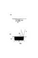
図9(a)(b)(c)は、本発明の第7の実施の形態のレーザ補修方法を示すものである。なお、第7の実施の形態のレーザ補修方法が適用されるレーザ発生装置の概略構成は、図1と同様なので、同図を援用するものとする。
【0081】
この場合、開口欠陥503の内部に水分などの内在物6が含まれているような場合、レーザ光4の焦点はずし距離10を大きくとりオーステナイト系ステンレス鋼501の表面を照射して加熱することにより開口欠陥503内部の水分を気化物7として蒸発させるようにした。
【0082】
具体的には、図9(a)に示すように開口欠陥503の表面に対してレーザ出力1000Wのレーザ光4を焦点はずし距離10を10mmに設定するとともに、スポット径を10mm程度にして走査あるいは、静止して照射することで過熱したところ、同図(b)に示すように開口欠陥503の内部に存在していた水分などの内在物6を蒸発させることができ、その後、同図(c)に示すように焦点はずし距離10をもとに戻して、レーザ光4をスポット径3mmで出力1000Wに設定して開口欠陥503表面を溶融することにより、溶融層505により開口欠陥503を封止するようにした。
【0083】
(第8の実施の形態)
この第8の実施の形態のレ−ザ補修方法は、欠陥除去後に、除去部と同一形状の埋め込み材をはめ込み、その周囲をレ−ザ溶接することを特徴としている。
【0084】
図10(a)(b)(c)は、本発明の第8の実施の形態のレーザ補修方法を示すものである。なお、第8の実施の形態のレーザ補修方法が適用されるレーザ発生装置の概略構成は、図1と同様なので、同図を援用するものとする。
【0085】
この場合、図10(a)に示すような開口欠陥503に対して、同図(b)に示すように欠陥部を機械加工、EDMあるいは、ドリルなどで完全に除去して拡張欠陥部11を形成し、同図(c)に示すように拡張欠陥部11の形状と同等あるいは、それに近い形状の埋め込み材12をはめ込むとともに、この埋め込み材12をレーザ溶接部131により封止を行うようにしている。
【0086】
具体的には、長さ20mm、深さ2mmの開口欠陥503を放電加工で長手方向に25mm、幅5mm、深さ2mmの大きさで取り除いて拡張欠陥部11を形成し、この拡張欠陥部11の形状と同じ形状のSUS316L材を埋め込み材12としてはめ込んだ後、レーザ出力1000Wのレーザ光4を、速度0.5m/minで走査しつつ、埋め込み材12周囲を溶接することで開口欠陥503を封止するようにした。
【0087】
(第9の実施の形態)
この第9の実施の形態のレ−ザ補修方法は、欠陥除去後に、除去部と同一形状のはめ込み材を埋め込み、その表面に溶化材を用いてレ−ザ肉盛溶接することを特徴としている。
【0088】
図11(a)(b)(c)は、本発明の第9の実施の形態のレーザ補修方法を示すものである。なお、第9の実施の形態のレーザ補修方法が適用されるレーザ発生装置の概略構成は、図1と同様なので、同図を援用するものとする。
【0089】
この場合も図11(a)に示すような開口欠陥503に対して、同図(b)に示すように欠陥部を完全に除去して拡張欠陥部11を形成し、同図(c)に示すように拡張欠陥部11の形状と同等あるいは、それに近い形状の埋め込み材12をはめ込み、その後、埋め込み材12の表面を溶化材8を用いてレーザ肉盛溶接部13をオーバーラップさせながら封止するようにしている。
【0090】
具体的には、この場合も開口欠陥503を放電加工で25mm×5mm×深さ2mmの大きさで除去したのち同様の形状をSUS316L材の埋め込み材12としてはめ込み、その後、レーザ出力1000Wのレーザ光4を、速度0.5m/min、スポット径3mmで、フィラーワイヤ(溶化材8)を1m/minで供給しながら走査して、レーザ肉盛溶接部13をオーバーラップさせながら埋め込み材12のすべて封止するようにした。このようにすれば、開口欠陥503を除去できるとともに、表面を耐食性の良い材料で封止することができる。
【0091】
(第10の実施の形態)
この第10の実施の形態のレ−ザ補修方法は、欠陥除去後に、除去部と同一形状のはめ込み材を埋め込み、その上から当て板をレ−ザシーム溶接することを特徴としている。
【0092】
図12(a)(b)(c)は、本発明の第10の実施の形態のレーザ補修方法を示すものである。なお、第10の実施の形態のレーザ補修方法が適用されるレーザ発生装置の概略構成は、図1と同様なので、同図を援用するものとする。
【0093】
この場合も、図12(a)に示すような開口欠陥503に対して、同図(b)に示すように欠陥部を完全に除去して拡張欠陥部11を形成し、同図(c)に示すように拡張欠陥部11の形状と同等あるいは、それに近い形状の埋め込み材12をはめ込み、その後、埋め込み材12上に当て板14を設け、この当て板14周囲をレーザ溶接部131により封止するようにしている。
【0094】
具体的には、この場合も開口欠陥503を放電加工で25mm×5mm×深さ2mmの大きさで除去したのち同様の形状をSUS316L材の埋め込み材12としてはめ込み、その上に当て板14を設置し、この当て板14の周囲をレーザ溶接部131により封止した。この場合、当て板14には、1mmの板厚のSUS316L材が用いられ、レーザ出力1000Wのレーザ光4を、速度0.5m/minで走査することで溶接を行った。なお、この方法では、最初から埋め込み材12に当て板14が一体に形成されたものをはめ込んでも同じ効果が得られる。
【0095】
(第11の実施の形態)
この第11の実施の形態のレ−ザ補修方法は、欠陥除去後に、除去部に溶化材をレ−ザで溶融させて埋め込み、その上にレ−ザ肉盛り溶接することを特徴としている。
【0096】
図13(a)(b)(c)(d)は、本発明の第11の実施の形態のレーザ補修方法を示すものである。なお、第11の実施の形態のレーザ補修方法が適用されるレーザ発生装置の概略構成は、図1と同様なので、同図を援用するものとする。
【0097】
この場合も、図13(a)に示すような開口欠陥503に対して、同図(b)に示すように放電加工により欠陥部を完全に除去して25mm×5mm×深さ2mmを除去し拡張欠陥部11を形成し、その後、同図(c)に示すように拡張欠陥部11に溶化材8を供給しながらレーザ光を照射することで溶化材8が溶融し、溶滴15として肉盛し、溶滴15が拡張欠陥部11中に一杯になったところで、同図(d)に示すように拡張欠陥部11周辺を含む領域に、さらに溶化材8を供給しながら表面にレーザ肉盛溶接部13を形成し、開口欠陥503を封止するようにしている。
【0098】
このようにしても、開口欠陥503の表面のレーザ補修が行えることが確認できた。
【0099】
(第12の実施の形態)
この第12の実施の形態のレ−ザ補修方法は、レ−ザ補修を行った後に、レ−ザ補修部およびその熱影響部の材料表面に入熱2KJ/cm以下のレ−ザ溶体化処理またはレ−ザ溶融処理または高耐食性材料の溶化材によりレ−ザ肉盛層を形成することを特徴としている。
【0100】
図14(a)(b)は、本発明の第12の実施の形態のレーザ補修方法を示すものである。なお、第12の実施の形態のレーザ補修方法が適用されるレーザ発生装置の概略構成は、図1と同様なので、同図を援用するものとする。
【0101】
この場合、上述した第2の実施の形態のようにレーザ光4を静止させて開口欠陥503を封止すると、溶融部では開口欠陥503を封止することはできるが、レーザ光4の入熱が多くなると、図14(a)に示すように熱影響部16に再鋭敏化層などの欠陥が発生することがある。このような状態では、この熱影響部16から再度開口欠陥が発生するおそれがあることから、さらに2KJ/cm以下の低入熱の条件で表面を溶融することで表面改質層17を形成することにより耐食性改善を図るようにしている。
【0102】
この場合、第4の実施の形態で述べたように高耐食性材料の溶化材を供給してレ−ザ肉盛層を形成しても同様な効果が得られる。
【0103】
(第13の実施の形態)
この第13の実施の形態のレーザ補修方法は、レ−ザ補修を行った後に、レーザ補修部およびその熱影響部に対してピーニングをおこない、材料表面に圧縮残留応力を付与することを特徴としている。
【0104】
図15(a)(b)(c)は、本発明の第13の実施の形態のレーザ補修方法を示すものである。なお、第13の実施の形態のレーザ補修方法が適用されるレーザ発生装置の概略構成は、図1と同様なので、同図を援用するものとする。
【0105】
この場合、図15(a)に示すような開口欠陥503に対して、同図(b)に示すように溶化材8を用いてレーザ肉盛溶接部13をオーバーラップさせながら封止した後、同図(c)に示すようにレーザ肉盛溶接部13によるレーザ溶融補修部を含む周辺にピーク値の高いGW以上で、パルス幅数10nsを有したレーザピーニング用レーザ光18をスキャニング照射することにより溶融させる。これにより溶融したことにより発生した引張残留応力を圧縮残留応力に改善することができ、開口欠陥503が下部で多少残っていても新たに開口するようなことを防止できる。
【0106】
(第14の実施の形態)
この第14の実施の形態のレ−ザ補修方法は、レーザ溶接中に加工点に対して側面からアルゴンガス、ヘリウムガスあるいは、窒素ガスを流すことにより発生するプルームあるいはプラズマを除去し、これにより得られるストレートな溶接ビードを用いて約1mm以上の開口亀裂の補修を行うもので、比較的深い開口欠陥の深い領域までレーザ補修できることを特徴としている。
【0107】
図16(a)(b)は、本発明の第14の実施の形態のレーザ補修方法を示すものである。なお、第14の実施の形態のレーザ補修方法が適用されるレーザ発生装置の概略構成は、図1と同様なので、同図を援用するものとする。
【0108】
この場合、図16(a)に示すような開口欠陥503に対してレーザ光4と同軸方向にアルゴンガス、Heガス、N2ガスなどを流してレーザ表面溶融、レーザ肉盛溶接などを行う。この場合、これらガスの流速を上げすぎると溶融池を乱れるため流速を下げて流すことが必要である。
【0109】
この状態から、キーホール溶接(通常のレーザ溶接で深い溶け込み形状が得られる)を行うと、ワインカップ形状といわれる、表面では、幅の広いビードが得られ、内部では、細い溶け込みビードが得られる。しかし、このようなワインカップ形状の溶接ビードは、表面の幅広い部分と下部の狭い部分での溶接ビードの境界の熱影響などによりHe割れが発生する場合がある。したがって、比較的表面の溶融幅と下部の溶融幅が同じような形状が好ましいが、このときの原因は、レーザ溶接中に材料表面に発生するプラズマやプルームの影響といわれている。
【0110】
そこで、図16(b)に示すように、レーザ光4の光軸に対して直交する方向から流速の速いガス20を流すことで表面に発生したプラズマやプルームを除去し、比較的ストレートな溶接ビード19を得るようにしている。また、このようなストレートな溶接ビード19は、オーバーラップして開口欠陥503を比較的深いところまで封止することができた。例えば、レーザ光4として、レーザ出力1500Wを用い、溶接速度0.5m/minの条件で約3mmの深さまで開口欠陥503を封止することができた。
【0111】
(第15の実施の形態)
この第15の実施の形態のレ−ザ補修溶接方法は、開口亀裂や深い欠陥を補修するレーザ補修において、集光されたレーザ光の位置に高耐食性材料の溶化材としてフィラーワイヤを供給しかつアルゴンガス、ヘリウムガスあるいは窒素ガスなどを流速をあげてレーザ光と同軸に流すと、溶融したフィラーワイヤが飛散するが、この飛散した高耐食性材料を開口亀裂中や材料表面に付着させて(レーザ溶射)欠陥を補修することを特徴としている。
【0112】
図17(a)(b)は、本発明の第15の実施の形態のレーザ補修方法を示すものである。なお、第15の実施の形態のレーザ補修方法が適用されるレーザ発生装置の概略構成は、図1と同様なので、同図を援用するものとする。
【0113】
この場合、図17(a)に示すような開口欠陥503に対して、同図(b)に示すようにノズル21を配置し、このノズル21からレーザ光4と、このレーザ光4と同軸方向からアルゴンガス、ヘリウムガスあるいは窒素ガスなどの溶融飛散ガス22を流速を上げて供給する。この場合、ノズル21の径は、約0.5から2mmと細いものが用いられる。そして、開口欠陥503の表面にレーザ光4を照射しつつ高耐食性材料のフィラーワイヤなどの溶化材8を供給する。この場合、開口欠陥503の表面に対するノズル21と溶化材8の位置は、10mm以上離しておく。また、溶化材8に照射されるレーザ光4のパワー密度は、105W/Cm2以上である。
【0114】
この状態で、ノズル21から流速の速い溶融飛散ガス22を流すことにより、レーザ光4の高いパワー密度により溶解された高耐食性材料の溶化材8が開口欠陥503内部や材料表面に付着する、いわゆるレーザ溶射により付着金属層23が形成され、開口欠陥503を封止することができた。
【0115】
(第16の実施の形態)
この第16の実施の形態のレーザ補修方法は、開口欠陥をEDMやドリルなど機械加工法により除去したのち、この除去された部分に付着金属層を形成させて封止することを特徴としている。
【0116】
図18(a)(b)(c)は、本発明の第16の実施の形態のレーザ補修方法を示すものである。なお、第16の実施の形態のレーザ補修方法が適用されるレーザ発生装置の概略構成は、図1と同様なので、同図を援用するものとする。
【0117】
この場合、図18(a)に示すような開口欠陥503に対して、同図(b)に示すように欠陥部を機械加工、EDMあるいは、ドリルなどで完全に除去して拡張欠陥部11を形成し、同図(c)に示すように第15の実施の形態で述べたと同様なレーザ溶射法により拡張欠陥部11を付着金属層23で埋めることにより、開口欠陥503を封止するようにしている。
【0118】
(第17の実施の形態)
この第17の実施の形態は、材料の表面に付着している高耐食性材料を再溶融させて欠陥を封止することを特徴としている。
【0119】
図19は、本発明の第17の実施の形態のレーザ補修方法を示すものである。なお、第17の実施の形態のレーザ補修方法が適用されるレーザ発生装置の概略構成は、図1と同様なので、同図を援用するものとする。
【0120】
この場合も、開口欠陥503に対して欠陥部を完全に除去して拡張欠陥部11を形成し、第15の実施の形態で述べたと同様なレーザ溶射法により拡張欠陥部11を付着金属層23で埋める。この場合、高耐食性材料の溶化材8をレーザ溶射することで得られた付着金属層23は、ポーラスであることから、さらに耐食性を高めるために付着金属層23の表面を2KJ/cm以下の入熱でレーザ照射することで溶融層505を形成し、開口欠陥503を補修する。
【0121】
以上の第1の実施の形態から第17の実施の形態では、開口欠陥や劣化した材料を補修するためのレーザ補修方法を説明したが、これらの実施の対象部位は、原子力構造物や核融合炉の構造物であり、以下にこれらの構造物に対する実施の形態について説明する。
【0122】
(第18の実施の形態)
この第18の実施の形態のレーザ補修方法は、原子力プラントや核融合炉機器の応力腐食割れ、疲労、Heバブル割れなどの欠陥やピットなどの欠陥を補修対象とし、焦点深度を可変制御するなどして溶融深さ・幅をコントロールしつつ、開口欠陥を封止することを特徴としている。
【0123】
図20は、本発明の第18の実施の形態のレーザ補修方法を示すものである。なお、第18の実施の形態のレーザ補修方法が適用されるレーザ発生装置の概略構成は、図1と同様なので、同図を援用するものとする。
【0124】
この場合、図20に示すように、構造物30の開口欠陥503としては、IGSCC、疲労亀裂、Heバブルによる亀裂など各種形状のものが考えれるので、それぞれの形状の開口欠陥503に応じた適切な溶融形状31を選択する必要がある。そこで、レーザ光32の出力、スポット径33、スキャニングなど走査方向34および走査速度35をそれぞれ設定して適切な溶融形状31を形成することにより、開口欠陥503のレーザ補修を行うようにしている。
【0125】
【発明の効果】
以上述べたように本発明によれば、疲労亀裂などの劣化により発生した開口欠陥に対して確実な欠陥補修を安定して行うことができ、これにより原子炉や、核融合炉の延命化を可能にし、国内の電力供給の低価格化と安定化に寄与することができる。
【図面の簡単な説明】
【図1】本発明のレーザ補修方法が適用されるレーザ発生装置の概略構成を示す図。
【図2】本発明の第1の実施の形態のレーザ補修方法を説明するための図。
【図3】第1の実施の形態に用いられるレーザ光による補修条件を説明するための図。
【図4】本発明の第2の実施の形態のレーザ補修方法を説明するための図。
【図5】本発明の第3の実施の形態のレーザ補修方法を説明するための図。
【図6】本発明の第4の実施の形態のレーザ補修方法を説明するための図。
【図7】本発明の第5の実施の形態のレーザ補修方法を説明するための図。
【図8】本発明の第6の実施の形態のレーザ補修方法を説明するための図。
【図9】本発明の第7の実施の形態のレーザ補修方法を説明するための図。
【図10】本発明の第8の実施の形態のレーザ補修方法を説明するための図。
【図11】本発明の第9の実施の形態のレーザ補修方法を説明するための図。
【図12】本発明の第10の実施の形態のレーザ補修方法を説明するための図。
【図13】本発明の第11の実施の形態のレーザ補修方法を説明するための図。
【図14】本発明の第12の実施の形態のレーザ補修方法を説明するための図。
【図15】本発明の第13の実施の形態のレーザ補修方法を説明するための図。
【図16】本発明の第14の実施の形態のレーザ補修方法を説明するための図。
【図17】本発明の第15の実施の形態のレーザ補修方法を説明するための図。
【図18】本発明の第16の実施の形態のレーザ補修方法を説明するための図。
【図19】本発明の第17の実施の形態のレーザ補修方法を説明するための図。
【図20】本発明の第18の実施の形態のレーザ補修方法を説明するための図。
【符号の説明】
1…レーザ発振器
2…光ファイバ
3…集光レンズ
4…レーザ光
5…補修対象
501…オーステナイト系ステンレス鋼
502…鋭敏化組織
503…開口欠陥
504…溶体化層
505…溶融層
6…内在物
7…気化物
8…溶化材
9…肉盛溶接部
10…距離
11…拡張欠陥部
12…込み材
13…レーザ肉盛溶接部
14…当て板
15…溶滴
16…熱影響部
17…表面改質層
18…レーザピーニング用レーザ光
19…溶接ビード
20…ガス
21…ノズル
22…溶融飛散ガス
23…付着金属層
30…構造物
31…溶融形状
32…レーザ光
33…スポット径
34…走査方向
35…走査速度[0001]
BACKGROUND OF THE INVENTION
The present invention relates to a laser repair method using a laser beam used for maintenance for restoration of soundness, for example, when a defect occurs in a substrate such as a reactor structure.
[0002]
[Prior art]
Conventionally, when a defect has occurred in a substrate such as a nuclear reactor structure, either replace the entire equipment that caused the defect, or install a reinforcing material or the like on the defective structure to remove the defective part. A method of reinforcing was taken.
[0003]
However, in the case of existing reactors, there is a possibility that the entire structure has deteriorated due to neutron irradiation due to long-term operation. The method required careful attention.
[0004]
In addition, it is necessary to repair defects in such reactor structures as early as possible, and it is desirable to repair them after removing the defects completely. Since it is a minimum condition to isolate from the environmental atmosphere, sealing of opening defects on the structure surface is also an effective means if the structural integrity can be confirmed.
[0005]
Therefore, conventionally, a laser repair method using TIG welding or the like has been considered as a repair method for a defect of a base material such as a structure.
[0006]
[Problems to be solved by the invention]
However, according to the laser repair method that employs such a TIG welding method, TIG welding is performed on a base material that may have been subjected to neutron irradiation during the long-term operation of the reactor and the entire structure may have deteriorated. If this is done, there is a risk that defects will occur again due to the large heat input. In addition, the TIG welding method is basically a method in which the base material is melted while generating an arc between the base material and the torch electrode. When an object is attached, water is in the gap of the defect, or the gap is large, there is a problem that no arc is generated and stable welding cannot be performed.
[0007]
The present invention has been made in view of the above circumstances, and it is an object of the present invention to provide a laser repair method capable of performing reliable defect repair stably.
[0008]
[Means for Solving the Problems]
The invention described in claim 1After removing the opening defect opened on the material surface to form an extended defect portion, an embedded material having the same shape as that of the extended defect portion is fitted, and the periphery of the embedded material is laser-welded to remove the residue inside the open defect. The opening defect surface is allowed to be sealed with the filling material.
In this way, after the defect is deleted, it can be completely backfilled for complete repair, and the soundness of the repaired part and its surroundings can be sufficiently improved.
[0009]
By doing so, since desensitization is simultaneously performed by laser repair, it is possible to improve the soundness (especially against stress corrosion cracking) of the repair area and its surroundings.
[0028]
Claim2In the described invention, an opening defect formed on the material surface is removed to form an extended defect portion, and then an embedded material having the same shape as that of the extended defect portion is fitted, and a laser is used on the surface of the embedded material using a solution material It is characterized by depositing and allowing the inside of the opening defect to remain and sealing the surface of the opening defect by the embedding material and laser overlay welding.
[0029]
Even if it does in this way, after performing defect deletion, it can completely backfill and complete repair is possible, and the soundness of a repaired part and its periphery can also be improved sufficiently.
[0030]
Claim3In the described invention, after opening defects formed on the material surface are removed to form extended defect portions, an embedded material having the same shape as the extended defect portions is fitted, and a backing plate is laser-seamed welded from above the embedded material. Then, the inside of the opening defect is allowed to be sealed, and the surface of the opening defect is sealed with the filling material and the contact plate.
[0031]
Even if it does in this way, after performing defect deletion, it can completely backfill and complete repair is possible, and the soundness of a repaired part and its periphery can also be improved sufficiently.
[0036]
Claim4The described invention is claimed.1 to 3In the invention described in any one of the above, peening is performed on the laser repaired portion and its heat-affected zone, and compressive residual stress is applied to the material surface.
[0037]
In this way, the tensile residual stress generated by melting can be improved to the compressive residual stress, and it is possible to prevent a new opening even if some opening defects remain.
[0040]
Claim5In the described invention, a feeler wire of a highly corrosion-resistant material is supplied to a position of a laser beam focused on an opening defect opened on the material surface, and argon gas, helium gas or nitrogen gas is allowed to flow coaxially with the laser beam. In this case, the melted melted material is scattered to allow the inside of the opening defect to remain, and the scattered metal layer of the highly corrosion-resistant material scattered on the surface of the opening defect is formed and sealed. .
[0041]
In this way, the opening defect can be sealed by the deposited metal layer formed by so-called laser spraying.
[0042]
Claim6The described invention is claimed.5In the invention described in (1), after the opening defect is removed and the extended defect portion is formed, the scattered high corrosion resistance material is attached to and laminated on the extended defect portion.
[0043]
In this way, it is possible to seal the opening defect with the deposited metal layer formed by the so-called laser spraying from the state where the defect is deleted and then backfilled.
[0044]
Claim7The described invention is claimed.5 or 6In the invention described in
[0045]
In this way, it is possible to reliably prevent the opening defect from newly opening.
[0046]
Claim8The described invention is claimed.1 to 7The invention described in any of the above is characterized by targeting defects in nuclear power plant or fusion reactor equipment.
[0047]
In this way, it is possible to repair defects such as stress corrosion cracking, fatigue, He bubble cracking, and defects such as pits in a nuclear power plant or fusion reactor equipment.
[0050]
DETAILED DESCRIPTION OF THE INVENTION
Hereinafter, embodiments of the present invention will be described with reference to the drawings.
[0051]
(First embodiment)
FIG. 1 shows a schematic configuration of a laser generator to which a laser repair method of the present invention is applied. In the figure, reference numeral 1 denotes a laser oscillator. An
[0052]
Next, a laser repair method for repairing a defect using such a laser generator will be described with reference to FIGS.
[0053]
In this case, the structure of the austenitic
[0054]
Then, the
[0055]
Note that the scanning method of the
[0056]
FIG. 3 shows repair conditions by the
[0057]
By doing so, the surface of the
[0058]
(Second Embodiment)
In the laser repair method according to the second embodiment, when an opening defect such as a minute crack or pitting opening on the material surface occurs, the laser beam is stopped without scanning and heated, It is characterized by melting the surface or all and sealing the opening defect.
[0059]
FIGS. 4A and 4B show a laser repair method according to the second embodiment of the present invention. In addition, since the schematic structure of the laser generator to which the laser repair method of 2nd Embodiment is applied is the same as that of FIG. 1, it shall use the same figure.
[0060]
In this case, as shown in FIG. 4A, the
[0061]
Even in this case, the inlet of the
[0062]
(Third embodiment)
The laser repair method according to the third embodiment is characterized by continuously repairing the process in which the laser beam described in the second embodiment is stopped and heated.
[0063]
FIGS. 5A, 5B, and 5C show a laser repair method according to the third embodiment of the present invention. In addition, since the schematic structure of the laser generator to which the laser repair method of 3rd Embodiment is applied is the same as that of FIG. 1, it shall use the same figure.
[0064]
In this case, as shown in FIG. 5 (a), when an
[0065]
In this way, it is possible to seal the internal material 6 contained inside the
[0066]
(Fourth embodiment)
The laser repair method according to the fourth embodiment is characterized in that a solution material is supplied to the melted portion at the time of laser irradiation in order to flatten the recess of the sealing portion.
[0067]
FIGS. 6A and 6B show a laser repair method according to the fourth embodiment of the present invention. In addition, since the schematic structure of the laser generator to which the laser repair method of 4th Embodiment is applied is the same as that of FIG. 1, it shall use the same figure.
[0068]
In this case, as shown in FIG. 6A, the welded portion 9 is built on the surface layer of the
[0069]
Specifically, the output of the
[0070]
(Fifth embodiment)
In the laser repair method of the fifth embodiment, after opening defects are sealed by laser repair welding, when a dent is generated on the surface, the laser is melted at the same location by using a solubilizate and the surface is melted. It is characterized by filling in the recess.
[0071]
FIGS. 7A and 7B show a laser repair method according to the fifth embodiment of the present invention. In addition, since the schematic structure of the laser generator to which the laser repair method of 5th Embodiment is applied is the same as that of FIG. 1, it shall use the same figure.
[0072]
In this case, as shown in FIG. 7A, the
[0073]
However, in this state, the molten metal for filling the
[0074]
Even in this case, it was possible to seal in a state where an
[0075]
(Sixth embodiment)
In the laser repair method of the sixth embodiment, when there is a long opening defect, a part of the weld formed by the laser repair method described above is wrapped so as to follow the opening defect. Thus, the opening defect is sealed by repeating the repair while moving the repair position.
[0076]
FIG. 8 shows a laser repair method according to the sixth embodiment of the present invention. In addition, since the schematic structure of the laser generator to which the laser repair method of 6th Embodiment is applied is the same as that of FIG. 1, it shall use the same figure.
[0077]
In this case, the welded portion 9 is formed on the surface layer of the
[0078]
Specifically, as laser irradiation conditions, a
[0079]
(Seventh embodiment)
In the laser repair method according to the seventh embodiment, before the opening defect is sealed, a heating source such as a high-frequency heating or a laser is used to heat the opening defect below the melting point of the object. It is characterized by vaporizing indigenous substances such as moisture or oil.
[0080]
FIGS. 9A, 9B and 9C show a laser repair method according to the seventh embodiment of the present invention. In addition, since the schematic structure of the laser generator to which the laser repair method of 7th Embodiment is applied is the same as that of FIG. 1, it shall use the same figure.
[0081]
In this case, when the inclusion 6 such as moisture is contained inside the
[0082]
Specifically, as shown in FIG. 9A, the
[0083]
(Eighth embodiment)
The laser repair method according to the eighth embodiment is characterized in that after a defect is removed, an embedded material having the same shape as that of the removed portion is fitted and the periphery thereof is laser-welded.
[0084]
FIGS. 10A, 10B and 10C show a laser repair method according to the eighth embodiment of the present invention. In addition, since the schematic structure of the laser generator to which the laser repair method of 8th Embodiment is applied is the same as that of FIG. 1, it shall use the same figure.
[0085]
In this case, with respect to the
[0086]
Specifically, the
[0087]
(Ninth embodiment)
The laser repair method according to the ninth embodiment is characterized in that after a defect is removed, a fitting material having the same shape as that of the removal portion is embedded, and laser overlay welding is performed on the surface using a solution material. .
[0088]
FIGS. 11A, 11B and 11C show a laser repair method according to the ninth embodiment of the present invention. In addition, since the schematic structure of the laser generator to which the laser repair method of 9th Embodiment is applied is the same as that of FIG. 1, it shall use the same figure.
[0089]
Also in this case, with respect to the
[0090]
Specifically, in this case as well, after removing the
[0091]
(Tenth embodiment)
The laser repair method according to the tenth embodiment is characterized in that after removing the defect, a fitting material having the same shape as that of the removed portion is embedded, and a backing plate is laser seam welded thereon.
[0092]
12A, 12B, and 12C show a laser repair method according to a tenth embodiment of the present invention. In addition, since the schematic structure of the laser generator to which the laser repair method of 10th Embodiment is applied is the same as that of FIG. 1, it shall use the same figure.
[0093]
Also in this case, with respect to the
[0094]
Specifically, in this case as well, after the
[0095]
(Eleventh embodiment)
The laser repair method according to the eleventh embodiment is characterized in that, after removing the defect, the melted material is melted and embedded in the removed portion with a laser, and laser build-up welding is performed thereon.
[0096]
FIGS. 13A, 13B, 13C, and 13D show a laser repair method according to the eleventh embodiment of the present invention. In addition, since the schematic structure of the laser generator to which the laser repair method of 11th Embodiment is applied is the same as that of FIG. 1, it shall use the same figure.
[0097]
Also in this case, for the
[0098]
Even in this way, it was confirmed that laser repair of the surface of the
[0099]
(Twelfth embodiment)
In the laser repair method of the twelfth embodiment, after laser repair, a laser solution with a heat input of 2 KJ / cm or less is applied to the material surface of the laser repair section and its heat-affected section. A laser build-up layer is formed by a treatment, a laser melting treatment, or a solubilizing material of a high corrosion resistance material.
[0100]
FIGS. 14A and 14B show a laser repair method according to a twelfth embodiment of the present invention. The schematic configuration of the laser generator to which the laser repair method of the twelfth embodiment is applied is the same as that shown in FIG.
[0101]
In this case, when the
[0102]
In this case, as described in the fourth embodiment, the same effect can be obtained even when a laser overlay layer is formed by supplying a solubilizing material of a high corrosion resistance material.
[0103]
(Thirteenth embodiment)
The laser repair method according to the thirteenth embodiment is characterized in that after laser repair is performed, peening is performed on the laser repaired portion and its heat-affected zone to impart compressive residual stress to the material surface. Yes.
[0104]
FIGS. 15A, 15B, and 15C show a laser repair method according to a thirteenth embodiment of the present invention. The schematic configuration of the laser generator to which the laser repair method of the thirteenth embodiment is applied is the same as that shown in FIG.
[0105]
In this case, for the
[0106]
(Fourteenth embodiment)
The laser repair method of the fourteenth embodiment removes the plume or plasma generated by flowing argon gas, helium gas or nitrogen gas from the side surface to the processing point during laser welding, thereby It repairs an opening crack of about 1 mm or more using the obtained straight weld bead, and is characterized by being able to repair a laser up to a deep region of a relatively deep opening defect.
[0107]
FIGS. 16A and 16B show a laser repair method according to a fourteenth embodiment of the present invention. The schematic configuration of the laser generator to which the laser repair method of the fourteenth embodiment is applied is the same as that shown in FIG.
[0108]
In this case, argon surface, He gas, N2 gas or the like is flowed in the same direction as the
[0109]
From this state, when performing keyhole welding (a deep penetration shape can be obtained by ordinary laser welding), a wide bead is obtained on the surface, which is called a wine cup shape, and a thin penetration bead is obtained inside. . However, in such a wine cup-shaped weld bead, a He crack may occur due to a thermal effect at the boundary of the weld bead in a wide portion of the surface and a narrow portion of the lower portion. Accordingly, a shape having a relatively similar melt width at the surface and a melt width at the lower portion is preferable, but the cause at this time is said to be the effect of plasma or plume generated on the material surface during laser welding.
[0110]
Therefore, as shown in FIG. 16B, plasma or plume generated on the surface is removed by flowing a
[0111]
(Fifteenth embodiment)
In the laser repair welding method according to the fifteenth embodiment, a filler wire is supplied as a solution of a highly corrosion-resistant material to the position of a focused laser beam in laser repair for repairing opening cracks and deep defects, and When argon gas, helium gas, or nitrogen gas is flowed coaxially with the laser beam at a higher flow rate, the molten filler wire will be scattered, but this scattered highly corrosion-resistant material will adhere to the open cracks and the material surface (laser Thermal spray) It is characterized by repairing defects.
[0112]
FIGS. 17A and 17B show a laser repair method according to the fifteenth embodiment of the present invention. The schematic configuration of the laser generator to which the laser repair method of the fifteenth embodiment is applied is the same as that shown in FIG.
[0113]
In this case, with respect to the
[0114]
In this state, by flowing the molten
[0115]
(Sixteenth embodiment)
The laser repair method according to the sixteenth embodiment is characterized in that after an opening defect is removed by a machining method such as EDM or a drill, an adhesion metal layer is formed on the removed portion and sealed.
[0116]
FIGS. 18A, 18B and 18C show a laser repair method according to the sixteenth embodiment of the present invention. The schematic configuration of the laser generator to which the laser repair method of the sixteenth embodiment is applied is the same as that shown in FIG.
[0117]
In this case, with respect to the
[0118]
(Seventeenth embodiment)
The seventeenth embodiment is characterized in that defects are sealed by remelting the high corrosion resistance material adhering to the surface of the material.
[0119]
FIG. 19 shows a laser repair method according to the seventeenth embodiment of the present invention. In addition, since the schematic structure of the laser generator to which the laser repair method of 17th Embodiment is applied is the same as that of FIG. 1, it shall use the same figure.
[0120]
Also in this case, the defective portion is completely removed from the
[0121]
In the first to seventeenth embodiments described above, the laser repair method for repairing the opening defect and the deteriorated material has been described. Embodiments of these structures will be described below.
[0122]
(Eighteenth embodiment)
In the laser repair method of the eighteenth embodiment, defects such as stress corrosion cracking, fatigue, He bubble cracking and defects such as pits of nuclear power plants and fusion reactor equipment are repaired, and the depth of focus is variably controlled. Thus, it is characterized by sealing opening defects while controlling the melting depth and width.
[0123]
FIG. 20 shows a laser repair method according to an eighteenth embodiment of the present invention. The schematic configuration of the laser generator to which the laser repair method of the eighteenth embodiment is applied is the same as that shown in FIG.
[0124]
In this case, as shown in FIG. 20, as the
[0125]
【The invention's effect】
As described above, according to the present invention, it is possible to stably perform reliable defect repair for opening defects caused by deterioration such as fatigue cracks, thereby extending the life of nuclear reactors and fusion reactors. And can contribute to lowering and stabilizing the domestic power supply.
[Brief description of the drawings]
FIG. 1 is a diagram showing a schematic configuration of a laser generator to which a laser repair method of the present invention is applied.
FIG. 2 is a diagram for explaining a laser repair method according to the first embodiment of the present invention.
FIG. 3 is a diagram for explaining repair conditions by laser light used in the first embodiment.
FIG. 4 is a diagram for explaining a laser repair method according to a second embodiment of the present invention.
FIG. 5 is a diagram for explaining a laser repair method according to a third embodiment of the present invention.
FIG. 6 is a diagram for explaining a laser repair method according to a fourth embodiment of the present invention.
FIG. 7 is a view for explaining a laser repair method according to a fifth embodiment of the present invention.
FIG. 8 is a diagram for explaining a laser repair method according to a sixth embodiment of the present invention.
FIG. 9 is a view for explaining a laser repair method according to a seventh embodiment of the present invention;
FIG. 10 is a view for explaining a laser repair method according to an eighth embodiment of the present invention;
FIG. 11 is a diagram for explaining a laser repair method according to a ninth embodiment of the present invention.
FIG. 12 is a diagram for explaining a laser repair method according to a tenth embodiment of the present invention.
FIG. 13 is a diagram for explaining a laser repair method according to an eleventh embodiment of the present invention.
FIG. 14 is a diagram for explaining a laser repair method according to a twelfth embodiment of the present invention.
FIG. 15 is a diagram for explaining a laser repair method according to a thirteenth embodiment of the present invention;
FIG. 16 is a view for explaining a laser repair method according to a fourteenth embodiment of the present invention.
FIG. 17 is a view for explaining a laser repair method according to a fifteenth embodiment of the present invention;
FIG. 18 is a view for explaining a laser repair method according to a sixteenth embodiment of the present invention;
FIG. 19 is a view for explaining a laser repair method according to a seventeenth embodiment of the present invention.
FIG. 20 is a diagram for explaining a laser repair method according to an eighteenth embodiment of the present invention;
[Explanation of symbols]
1 ... Laser oscillator
2 ... Optical fiber
3 ... Condensing lens
4 ... Laser light
5 ... repair target
501 ... Austenitic stainless steel
502 ... Sensitized tissue
503: Opening defect
504 ... Solution layer
505 ... Molten layer
6 ... Built-in materials
7 ... Vaporized
8 ... Solubilized material
9 ... Overlay weld
10 ... Distance
11 ... Extended defect
12 ...
13 ... Laser overlay welding
14 ...
15 ...
16 ... Heat affected zone
17 ... Surface modified layer
18 ... Laser beam for laser peening
19 ... weld bead
20 ... Gas
21 ... Nozzle
22 ... Molten spatter gas
23 ... Adhering metal layer
30 ... Structure
31 ... Melting shape
32 ... Laser light
33 ... Spot diameter
34 ... Scanning direction
35 ... Scanning speed
Claims (8)
Translated fromJapanesePriority Applications (1)
| Application Number | Priority Date | Filing Date | Title |
|---|---|---|---|
| JP2000097116AJP4246878B2 (en) | 2000-03-31 | 2000-03-31 | Laser repair method |
Applications Claiming Priority (1)
| Application Number | Priority Date | Filing Date | Title |
|---|---|---|---|
| JP2000097116AJP4246878B2 (en) | 2000-03-31 | 2000-03-31 | Laser repair method |
Publications (2)
| Publication Number | Publication Date |
|---|---|
| JP2001287062A JP2001287062A (en) | 2001-10-16 |
| JP4246878B2true JP4246878B2 (en) | 2009-04-02 |
Family
ID=18611785
Family Applications (1)
| Application Number | Title | Priority Date | Filing Date |
|---|---|---|---|
| JP2000097116AExpired - Fee RelatedJP4246878B2 (en) | 2000-03-31 | 2000-03-31 | Laser repair method |
Country Status (1)
| Country | Link |
|---|---|
| JP (1) | JP4246878B2 (en) |
Cited By (1)
| Publication number | Priority date | Publication date | Assignee | Title |
|---|---|---|---|---|
| EP3702090A1 (en)* | 2019-02-19 | 2020-09-02 | Mitsubishi Heavy Industries, Ltd. | Weldment manufacturing method, weldment manufacturing system, and weldment |
Families Citing this family (24)
| Publication number | Priority date | Publication date | Assignee | Title |
|---|---|---|---|---|
| JP4664569B2 (en)* | 2002-05-08 | 2011-04-06 | 株式会社東芝 | Method and apparatus for sealing surface defects |
| US7097720B2 (en)* | 2003-04-30 | 2006-08-29 | General Electric Company | Lower fluence boundary laser shock peening |
| US7362486B2 (en) | 2004-09-29 | 2008-04-22 | Ricoh Company, Ltd. | Optical scanning device with at least one resin lens for controlling a beam waist position shift |
| JP4847148B2 (en)* | 2006-02-06 | 2011-12-28 | バブコック日立株式会社 | Repair method for nuclear pressure vessel structure |
| JP2009095851A (en) | 2007-10-16 | 2009-05-07 | Toshiba Corp | Sealing method of surface crack |
| WO2010110874A1 (en)* | 2009-03-24 | 2010-09-30 | Seitz Michael W | Coating of fatigue corrosion cracked metallic tubes |
| DE102009016260A1 (en)* | 2009-04-03 | 2010-10-07 | Fraunhofer-Gesellschaft zur Förderung der angewandten Forschung e.V. | Method of welding and component |
| JP5860264B2 (en)* | 2011-10-21 | 2016-02-16 | 株式会社Ihi | How to repair cracks |
| JP6041289B2 (en)* | 2012-02-28 | 2016-12-07 | 三菱重工業株式会社 | Underwater welding repair method |
| WO2015065606A1 (en) | 2013-10-30 | 2015-05-07 | United Technologies Corporation | Laser powder deposition weld rework for gas turbine engine non-fusion weldable nickel castings |
| JP5677554B1 (en)* | 2013-11-22 | 2015-02-25 | モリマシナリー株式会社 | Upper or lower eyelid used for rotary press, and method for reforming upper end face of upper or lower eyelid |
| JP6272150B2 (en)* | 2014-03-28 | 2018-01-31 | 日立Geニュークリア・エナジー株式会社 | Laser apparatus and method for cutting or hanging in-reactor equipment or fuel debris in boiling water nuclear power plant using the same |
| DE102015222084A1 (en)* | 2015-11-10 | 2017-05-11 | Fraunhofer-Gesellschaft zur Förderung der angewandten Forschung e.V. | Parameters during buildup welding with oscillating solidification front |
| WO2018099926A1 (en)* | 2016-12-02 | 2018-06-07 | Tata Steel Ijmuiden B.V. | Method for laser surface treatment of furnace furniture |
| JP7032707B2 (en) | 2018-04-27 | 2022-03-09 | 株式会社Ihi | Laser welding method for repair and laser welding equipment for repair |
| BE1026209B1 (en)* | 2018-11-15 | 2019-11-07 | Westinghouse Electric Belgium | PROCESS FOR REPAIRING BY DEPOSITION OF LASER METALLIC POWDER |
| UA126105C2 (en)* | 2018-11-15 | 2022-08-10 | Вестінґхаус Електрик Белджем | Repair process using laser metal powder deposition |
| EP3919220A4 (en) | 2019-02-01 | 2022-11-02 | IHI Corporation | Crack repair method |
| CN111621733B (en)* | 2020-05-15 | 2022-07-19 | 浙江博星工贸有限公司 | A working method of a camshaft repair system |
| CN114211109B (en)* | 2022-01-07 | 2024-04-16 | 哈电发电设备国家工程研究中心有限公司 | A welding method for stainless steel microporous fiberboard |
| CN115156839B (en)* | 2022-08-19 | 2023-12-19 | 华南理工大学 | Method for repairing defects of reboiler tank body |
| CN116926536A (en)* | 2023-07-27 | 2023-10-24 | 燕山大学 | Stainless steel braided wire strengthening method and device based on laser alloying |
| DE102024002492A1 (en) | 2024-08-01 | 2024-10-31 | Mercedes-Benz Group AG | Method and device for repairing a faulty weld |
| CN119489272A (en)* | 2024-10-31 | 2025-02-21 | 中国航发南方工业有限公司 | A pulse laser repair method for aero-engine casting K438 bearing seat bracket |
- 2000
- 2000-03-31JPJP2000097116Apatent/JP4246878B2/ennot_activeExpired - Fee Related
Cited By (2)
| Publication number | Priority date | Publication date | Assignee | Title |
|---|---|---|---|---|
| EP3702090A1 (en)* | 2019-02-19 | 2020-09-02 | Mitsubishi Heavy Industries, Ltd. | Weldment manufacturing method, weldment manufacturing system, and weldment |
| US11458565B2 (en) | 2019-02-19 | 2022-10-04 | Mitsubishi Heavy Industries, Ltd. | Weldment manufacturing method, weldment manufacturing system, and weldment |
Also Published As
| Publication number | Publication date |
|---|---|
| JP2001287062A (en) | 2001-10-16 |
Similar Documents
| Publication | Publication Date | Title |
|---|---|---|
| JP4246878B2 (en) | Laser repair method | |
| EP1249300B1 (en) | Laser repair method for nickel base superalloys with high gamma prime content | |
| US4642446A (en) | Laser welding of galvanized steel | |
| EP2373456B1 (en) | Method of repairing a metallic artefact | |
| KR101226998B1 (en) | Method of sealing of surface cracks | |
| US20120325786A1 (en) | Welding process and a welding arrangement | |
| US20110049112A1 (en) | Combustion cap effusion plate laser weld repair | |
| JP2003053533A (en) | Structure repair method and repair welding apparatus | |
| JPH07236984A (en) | Laser processing method and apparatus | |
| JP3115456B2 (en) | Laser welding method for galvanized steel sheet | |
| JP3079902B2 (en) | Welding repair method for reactor internals | |
| Kim et al. | Relationship between the weldability and the process parameters for laser-TIG hybrid welding of galvanized steel sheets | |
| JPH0775893A (en) | Structure repair method and preventive maintenance method | |
| JP2021167026A (en) | Repair method for weld defect | |
| EP1003624A1 (en) | Method of laser beam welding of zinc-coated steel sheet | |
| CN101394967A (en) | Repair welding method in water | |
| JP4304913B2 (en) | How to repair cracked defects | |
| KR20040058615A (en) | Apparatus for Eliminating of Coating Material on Coated Metal Plate and Welding Method Using That | |
| WO2020158878A1 (en) | Crack repair method | |
| JPS6037282A (en) | Method and device for laser welding | |
| JPH1076363A (en) | Strength improvement method for high energy density heat source welds | |
| JP2000246438A (en) | Structure and its welding method | |
| Fujinaga et al. | Development of an all-position YAG laser butt welding process with addition of filler wire | |
| JPH06289183A (en) | Repair of structure in nuclear reactor | |
| JP2005230838A (en) | Laser welding method and laser welding apparatus for nickel base alloy welded structure |
Legal Events
| Date | Code | Title | Description |
|---|---|---|---|
| A621 | Written request for application examination | Free format text:JAPANESE INTERMEDIATE CODE: A621 Effective date:20050818 | |
| A977 | Report on retrieval | Free format text:JAPANESE INTERMEDIATE CODE: A971007 Effective date:20080111 | |
| A131 | Notification of reasons for refusal | Free format text:JAPANESE INTERMEDIATE CODE: A131 Effective date:20080122 | |
| A521 | Written amendment | Free format text:JAPANESE INTERMEDIATE CODE: A523 Effective date:20080324 | |
| A131 | Notification of reasons for refusal | Free format text:JAPANESE INTERMEDIATE CODE: A131 Effective date:20080603 | |
| A521 | Written amendment | Free format text:JAPANESE INTERMEDIATE CODE: A523 Effective date:20080804 | |
| TRDD | Decision of grant or rejection written | ||
| A01 | Written decision to grant a patent or to grant a registration (utility model) | Free format text:JAPANESE INTERMEDIATE CODE: A01 Effective date:20090106 | |
| A01 | Written decision to grant a patent or to grant a registration (utility model) | Free format text:JAPANESE INTERMEDIATE CODE: A01 | |
| A61 | First payment of annual fees (during grant procedure) | Free format text:JAPANESE INTERMEDIATE CODE: A61 Effective date:20090109 | |
| FPAY | Renewal fee payment (event date is renewal date of database) | Free format text:PAYMENT UNTIL: 20120116 Year of fee payment:3 | |
| FPAY | Renewal fee payment (event date is renewal date of database) | Free format text:PAYMENT UNTIL: 20130116 Year of fee payment:4 | |
| FPAY | Renewal fee payment (event date is renewal date of database) | Free format text:PAYMENT UNTIL: 20130116 Year of fee payment:4 | |
| FPAY | Renewal fee payment (event date is renewal date of database) | Free format text:PAYMENT UNTIL: 20140116 Year of fee payment:5 | |
| LAPS | Cancellation because of no payment of annual fees |