JP4245806B2 - Vertebral osteosynthesis system for anterior fixation - Google Patents
Vertebral osteosynthesis system for anterior fixationDownload PDFInfo
- Publication number
- JP4245806B2 JP4245806B2JP2000545454AJP2000545454AJP4245806B2JP 4245806 B2JP4245806 B2JP 4245806B2JP 2000545454 AJP2000545454 AJP 2000545454AJP 2000545454 AJP2000545454 AJP 2000545454AJP 4245806 B2JP4245806 B2JP 4245806B2
- Authority
- JP
- Japan
- Prior art keywords
- connecting rod
- screw
- connector
- vertebral
- branch
- Prior art date
- Legal status (The legal status is an assumption and is not a legal conclusion. Google has not performed a legal analysis and makes no representation as to the accuracy of the status listed.)
- Expired - Fee Related
Links
- 230000008878couplingEffects0.000claimsdescription8
- 238000010168coupling processMethods0.000claimsdescription8
- 238000005859coupling reactionMethods0.000claimsdescription8
- 238000005452bendingMethods0.000description2
- 230000001054cortical effectEffects0.000description2
- 238000002271resectionMethods0.000description2
- 210000000988bone and boneAnatomy0.000description1
- 238000006243chemical reactionMethods0.000description1
- 238000012937correctionMethods0.000description1
- 238000004519manufacturing processMethods0.000description1
- 229910052751metalInorganic materials0.000description1
- 239000002184metalSubstances0.000description1
- 150000002739metalsChemical class0.000description1
- 238000000034methodMethods0.000description1
- 230000037361pathwayEffects0.000description1
- 230000002265preventionEffects0.000description1
- 238000010079rubber tappingMethods0.000description1
- 206010039722scoliosisDiseases0.000description1
- 238000011477surgical interventionMethods0.000description1
Images


Classifications
- A—HUMAN NECESSITIES
- A61—MEDICAL OR VETERINARY SCIENCE; HYGIENE
- A61B—DIAGNOSIS; SURGERY; IDENTIFICATION
- A61B17/00—Surgical instruments, devices or methods
- A61B17/56—Surgical instruments or methods for treatment of bones or joints; Devices specially adapted therefor
- A61B17/58—Surgical instruments or methods for treatment of bones or joints; Devices specially adapted therefor for osteosynthesis, e.g. bone plates, screws or setting implements
- A61B17/68—Internal fixation devices, including fasteners and spinal fixators, even if a part thereof projects from the skin
- A61B17/70—Spinal positioners or stabilisers, e.g. stabilisers comprising fluid filler in an implant
- A61B17/7001—Screws or hooks combined with longitudinal elements which do not contact vertebrae
- A61B17/7041—Screws or hooks combined with longitudinal elements which do not contact vertebrae with single longitudinal rod offset laterally from single row of screws or hooks
- A—HUMAN NECESSITIES
- A61—MEDICAL OR VETERINARY SCIENCE; HYGIENE
- A61B—DIAGNOSIS; SURGERY; IDENTIFICATION
- A61B17/00—Surgical instruments, devices or methods
- A61B17/56—Surgical instruments or methods for treatment of bones or joints; Devices specially adapted therefor
- A61B17/58—Surgical instruments or methods for treatment of bones or joints; Devices specially adapted therefor for osteosynthesis, e.g. bone plates, screws or setting implements
- A61B17/68—Internal fixation devices, including fasteners and spinal fixators, even if a part thereof projects from the skin
- A61B17/70—Spinal positioners or stabilisers, e.g. stabilisers comprising fluid filler in an implant
- A61B17/7001—Screws or hooks combined with longitudinal elements which do not contact vertebrae
- A61B17/7035—Screws or hooks, wherein a rod-clamping part and a bone-anchoring part can pivot relative to each other
- A61B17/7037—Screws or hooks, wherein a rod-clamping part and a bone-anchoring part can pivot relative to each other wherein pivoting is blocked when the rod is clamped
- A—HUMAN NECESSITIES
- A61—MEDICAL OR VETERINARY SCIENCE; HYGIENE
- A61B—DIAGNOSIS; SURGERY; IDENTIFICATION
- A61B17/00—Surgical instruments, devices or methods
- A61B17/56—Surgical instruments or methods for treatment of bones or joints; Devices specially adapted therefor
- A61B17/58—Surgical instruments or methods for treatment of bones or joints; Devices specially adapted therefor for osteosynthesis, e.g. bone plates, screws or setting implements
- A61B17/68—Internal fixation devices, including fasteners and spinal fixators, even if a part thereof projects from the skin
- A61B17/70—Spinal positioners or stabilisers, e.g. stabilisers comprising fluid filler in an implant
- A61B17/7001—Screws or hooks combined with longitudinal elements which do not contact vertebrae
- A61B17/7044—Screws or hooks combined with longitudinal elements which do not contact vertebrae also having plates, staples or washers bearing on the vertebrae
- A—HUMAN NECESSITIES
- A61—MEDICAL OR VETERINARY SCIENCE; HYGIENE
- A61B—DIAGNOSIS; SURGERY; IDENTIFICATION
- A61B17/00—Surgical instruments, devices or methods
- A61B17/56—Surgical instruments or methods for treatment of bones or joints; Devices specially adapted therefor
- A61B17/58—Surgical instruments or methods for treatment of bones or joints; Devices specially adapted therefor for osteosynthesis, e.g. bone plates, screws or setting implements
- A61B17/68—Internal fixation devices, including fasteners and spinal fixators, even if a part thereof projects from the skin
- A61B17/70—Spinal positioners or stabilisers, e.g. stabilisers comprising fluid filler in an implant
- A61B17/7001—Screws or hooks combined with longitudinal elements which do not contact vertebrae
- A61B17/7035—Screws or hooks, wherein a rod-clamping part and a bone-anchoring part can pivot relative to each other
- A61B17/704—Screws or hooks, wherein a rod-clamping part and a bone-anchoring part can pivot relative to each other the longitudinal element passing through a ball-joint in the screw head
Landscapes
- Health & Medical Sciences (AREA)
- Orthopedic Medicine & Surgery (AREA)
- Life Sciences & Earth Sciences (AREA)
- Neurology (AREA)
- Surgery (AREA)
- Heart & Thoracic Surgery (AREA)
- Engineering & Computer Science (AREA)
- Biomedical Technology (AREA)
- Nuclear Medicine, Radiotherapy & Molecular Imaging (AREA)
- Medical Informatics (AREA)
- Molecular Biology (AREA)
- Animal Behavior & Ethology (AREA)
- General Health & Medical Sciences (AREA)
- Public Health (AREA)
- Veterinary Medicine (AREA)
- Surgical Instruments (AREA)
- Prostheses (AREA)
- Orthopedics, Nursing, And Contraception (AREA)
Abstract
Description
Translated fromJapanese【0001】
この発明は、脊椎骨接合システム、特に前方固定のための脊椎骨接合システムに関するものである。
【0002】
連結要素が板状体によって形成された前方固定のための脊椎骨接合システムが知られており、また、連結要素が棒状体によって形成された脊椎骨接合システムも知られている。板状体に基づくシステムは、かさばっているため、すべて内視鏡の経路を通して使用するときには、使用が困難である。しかも、これらは、寸法(長さ)が制限されるため、単一の脊椎骨あるいはおそらく2つの脊椎骨に関する簡単な脊椎切除のためだけに使用することができる。この種の移植片で脊柱側彎症を治療することは不可能である。最後に、これらの板状体は、それらが固定される脊椎骨の形態に適合させることは困難である。さらにまた、棒状体に基づくシステムには、普通、かなりかさばった連結具が備わっており、必ずしも内視鏡の経路を通して使用することができるとは限らない。
【0003】
脊椎骨接合装置は、国際特許出願WO−96/27340号に当たるフランス特許出願FR−2,731,344号の明細書からも知られており、この装置には、連結ロッドを締め付けることのできる2つの分岐部のある連結具が備わっており、これらの分岐部が脊椎骨茎部のねじにねじ合うことができるようにされている。しかしながら、この連結具は、脊椎骨茎部における脊椎の後方固定のために充分に適合しているものの、脊椎の前方固定の目的では充分な安定性を保証することができない。
【0004】
この発明の1つの目的は、前方固定のために適合され、取り付けやすく、脊椎における良好な安定性を保証し、かつ、内視鏡の経路を通して互換可能に取り付けられる、異なった種類の脊椎骨接合システムを利用可能にすることである。
【0005】
この目的を達成するために、この発明によれば、細長い連結ロッドと、脊椎骨ねじと、その連結ロッドをそれらの間に締め付けることのできる2つの分岐部を含んでおり、少なくとも下方分岐部がその脊椎骨ねじにねじ合うことのできる連結具とを備えてなる脊椎骨接合システムであって、このシステムが、第2脊椎骨ねじを備え、下方分岐部が第2脊椎骨ねじにねじ合うことのできる張出部分を有している脊椎骨接合システムが提供される。
【0006】
したがって、連結具は、それを通常の経路あるいは内視鏡の経路から定位置に入れることができるように、かさを減らすことができるようになる。さらにまた、2つのねじによって連結具を脊椎骨へ固定すると、正確であって安定したかつ信頼できる、連結具の、したがって連結ロッドの位置決めが可能になる。この連結具は、連結ロッドおよび脊椎骨ねじに容易に接続できる。これらの利点によって、この連結具は、脊椎の前方固定に特に良好に適合するようになる。この連結具は、単一片であるのが好ましいであろう。
【0007】
前記張出部分には第2脊椎骨ねじを受け容れるためのオリフィスがあるのが好ましい。
【0008】
この張出部分には、脊椎骨から遠いように意図されたオリフィスの一端に球状の凹所があるのが好ましい。
【0009】
こういうわけで、このシステムを脊椎骨の形態にいっそうよく適合させるために、その連結具に対する第2脊椎骨ねじの角度を調節することができる。
【0010】
脊椎骨から遠いように意図された1つの分岐部には第1脊椎骨ねじを収容するためのオリフィスがあり、脊椎骨から遠いように意図されたオリフィスの一端には球状の凹所があるのが好ましい。
【0011】
こういうわけで、このシステムを脊椎骨の形態にいっそうよく適合させるために、その連結具に対する第1脊椎骨ねじの角度を調節することができる。
【0012】
張り出した分岐部は、手によって、とりわけ道具を使って曲げることができるのが好ましい。
【0013】
こういうわけで、この連結具の形状を脊椎骨の形状に適合させることができ、その連結具を脊椎骨のきわめて近くに位置させることができる。
【0014】
第1脊椎骨ねじには、この第1脊椎骨ねじに関する回転によってその連結具を動かないように固定するために、頭部と、この頭部からはっきり区別することができるとともに、脊椎骨に隣接するように意図された分岐部の1つと協働することのできるフランジ部とが含まれている。
【0015】
したがって、いったん取り付けられると、第1脊椎骨ねじに対してその連結具が動かないように固定されるのに先立って、他の要素の位置決めが促進されるとともに、取り付けられたシステムを最終的に締め付ける前に、このシステムのすべての位置修正を行うことが可能になる。
【0016】
フランジ部には、摩擦によってその連結具を動かないように固定することのできる面、特に円錐面があるのが好ましい。
【0017】
第1脊椎骨ねじにはねじ付きオリフィスがあり、このシステムには、このオリフィスとの間にねじ−ナット連結を構成することができるとともに、前記分岐部を締め付けるために脊椎骨から遠いように意図されたその分岐部の1つを受けることができる締付用ねじが備わっているのが好ましい。
【0018】
こういうわけで、第1脊椎骨ねじ、連結具および第2脊椎骨ねじをまず嵌めて、そのすぐ後に、その組立体の締め付けを進めるために前記締付用ねじを取り付けることができる。
【0019】
このシステムには、前記ロッドに嵌めることができかつ前記分岐部どうしの間に収容することのできるリングが備わっているのが好ましく、連結具とこのリングとは、その分岐部が締め付けられる前に、相互に垂直な2つの平面においてそのロッドの方位を調節することができるように設計されているのが好ましい。
【0020】
2つの分岐部は、それらの分岐部のために、互いの方へ向いて閉じられるように、弾性的に変形することのできる単一構成要素の一部を形成するのが好ましい。
【0021】
連結具は、その連結具に対する第1連結ロッドの角度位置を選ぶことによって、脊椎骨ねじおよびその第1連結ロッドに固定することができるものであるのが好ましい。
【0022】
前記のフランス特許出願FR−2,731,344号の明細書における装置では、脊椎の前方固定のための充分な剛性が生じない、ということもわかった。
【0023】
したがって、この発明の副次的な目的は、前方固定のために適しており、かつ、特に高度な剛性が保証されるシステムを提供することである。
【0024】
このような目的を達成するために、このシステムには細長い第2連結ロッドが備わっており、連結具は2つの連結ロッドに同時に固定することのできるものであるのが好ましい。
【0025】
こういうわけで、2つの連結ロッドが存在することにより、その組立体を複雑にすることなく、そのさまざまな構成要素の体積を増大させる(内視鏡の経路を介した取り付けを互換可能なものにする)ことなく、また、第1連結ロッドに対する連結具の角度位置を調節する可能性を維持しながら、このシステムにきわめて大きい剛性が付与される。この発明に係るシステムには、2つの連結ロッドにおける同一の曲げは必要でない。さらにまた、連結具の数は少ないままにすることができる。
【0026】
このシステムは、第2連結ロッドを連結具に対する単一の角度位置だけでその連結具に固定することができるように設計されているのが好ましい。
【0027】
こういうわけで、第2連結ロッドの形状によって、それに固定される連結具の相対角度位置が決められる。それゆえ、この角度位置は、この連結ロッドに付与された従来の曲率に依存して、製造の時点かあるいは、好ましくは外科的介入の際に、あらかじめ選ぶことができる。
【0028】
第2連結ロッドは第1連結ロッドよりも曲げに対する抵抗性が小さいのが好ましい。
【0029】
したがって、第1連結ロッドには主として連結具の支持を保証する機能があり、第2連結ロッドには主として連結具の相対角度位置決めを保証する機能がある。
【0030】
前記分岐部は同時に2つの連結ロッドを締め付けることのできるものであるのが好ましい。
【0031】
このシステムは、第2連結ロッドが連結具に固定されたときにその連結具からの離脱のために第2連結ロッドが第2脊椎骨ねじの軌跡を延びるように、設計されているのが好ましい。
【0032】
こういうわけで、第2脊椎骨ねじは都合の悪いときに現れるようになるのが防止される。
【0033】
このシステムには第2連結具が備わっており、2つの連結具はそれぞれが2つの連結ロッドのそれぞれに同時に固定することができるものであるのが好ましい。
【0034】
このシステムは脊椎の前方に固定するように意図されているのが好ましい。
【0035】
この発明はまた、細長い連結ロッドを締め付けることのできる2つの分岐部を含んでおり、少なくとも1つの下方分岐部には脊椎骨ねじにねじ合うことのできるオリフィスがあり、かつ、下方分岐部には第2脊椎骨ねじにねじ合うことのできるオリフィスのある張出部分がある脊椎骨接合システムのための連結具を提供するものである。
この連結具はこの発明に係るシステムの一部を形成するように適合されている。
【0036】
この発明の他の特徴構成および利点は、非限定的な例として与えられた2つの好ましい実施形態の以下の説明から、いっそう明らかになる。
【0037】
図1〜図8によれば、この発明に係るシステムは、第1実施形態では、円形断面の細長い連結ロッド2と、これに固定することのできる数個の連結具半組立体4とを備えてなる。これらの半組立体のうち2個は図1に認めることができ、1個は図2に認めることができるが、それぞれの半組立体は、連結具6、第1脊椎骨ねじすなわち主ねじ8、締付用ねじ10、第2脊椎骨ねじすなわち副ねじ12、およびリング13を備えてなる。
【0038】
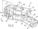
図3および図4によれば、連結具6には2つの分岐部16が含まれており、これらは、向かい合わせにかつ互いからある距離だけ延びて、連結具にU字状の輪郭を付与している。連結具6には、それらの分岐部16の幅に垂直であってそれらの長さに平行な対称平面Sが含まれている。図6によれば、連結具には、分岐部16の起点に、円筒状であって同軸の内面18,20がある。これらの内面18,20には、平面Sに垂直な軸22と異なった半径とがあり、半径の大きい方の面20は、相異なる2つの部分にあって、平面Sが横切っている、半径の小さい方の面18の一方側部に延びている。2つの面18,20によって、その接続点に、軸22のある2つの円形端部24が形成されている。
【0039】
リング13には、円筒状の内面26と球状の外面28とがあり、これらは同軸である。円筒状の内面26には、リング13が、その軸に沿って一方側部に長孔が開けられて、ロッド2に滑り嵌めとして取り付けることができるように、ロッド2の半径にほぼ等しい半径がある。さらにまた、リング13は、円筒状内面18,20に対向して分岐部16の間に入り込むことができる。リング13における球状の外面28には、この位置で連結具6の端部24がリング13における球状の外面28に線接触し、かつ、そのためのベアリングとして役立つように適合された半径がある。この位置では、分岐部16の締め付けの前に、リング13に嵌められたロッド2の角度位置を、相互に垂直な2つの平面で、ロッド2が平面Sに垂直であるロッド2の平均位置の一方の側において例えば15°の振幅にわたって調節することができる。
【0040】
分岐部16にはそれぞれ、平滑な2つの円筒状開口があり、これらの開口は、この場合、互いに同軸に反対方向へ延びている貫通オリフィス30である。主ねじ8は、二重皮質性脊椎骨ねじであり、それ自体、知られた方法で、この目的のためにねじが切られた本体がある。主ねじ8には頭部32があり、頭部32には平滑な円筒状外面34がある。このねじには、頭部と本体との接続点に、環状のフランジ部36が含まれている。フランジ部36には、このねじの長手軸に垂直な下面と、このねじの頭部32に向かって位置する円錐台の最も狭い断面を有する円錐台状の上面38とがある。頭部32には、このねじの本体に同軸であるねじ付きオリフィス39があり、また、オリフィス39のねじ面には、六角ソケットなどの非環状形状が形成されている。締付用ねじ10には、このオリフィス39とねじ−ナット連結を形成することのできる、ねじの切られた本体42と、六角ソケットが形成されたねじ頭部44とが含まれている。頭部44には、球状かつ凸状の下部外面46があり、この外面の最も狭い断面はそのねじの先端に向かって位置している。
【0041】
わかりやすくするためにここで下方分岐部と称する一方の分岐部16には、連結具の円筒状面18,20から離れる方向へ延びている張出部分50がある。この部分は脊椎骨に近接するように意図された分岐部である。2つの分岐部16は、フランジ部36の上面38が当接する下方分岐部から始まるように導入された主ねじ8の頭部32が同時に嵌まり込みことのできる部分である。締付用ねじ10は次に、上方分岐部16から始まるように主ねじ8の頭部32の中へ導入される。主ねじ8の頭部32におけるねじ10の締め付けによって、2つの分岐部16が互いの方へ向かって近づくようになるとともに、連結具6に対して選ばれた位置でロッド2の摩擦緊結が起きる。
【0042】
下方分岐部16のオリフィス30には、上方分岐部から離れかつ脊椎骨へ向かうように意図された下端がある。この下端には、摩擦によって、主ねじ8の軸に対する連結具6の回転阻止に影響を及ぼすために、フランジ部36の上面38に接触するように意図された凹状球形の凹所40が備わっている。上方分岐部16のオリフィス30には、下方分岐部から離れかつ脊椎骨から離れるように意図された上端が備わっている。この上端には、締付用ねじ10の頭部44における凸状球形の下面46に当接するように意図され、かつ、連結具に対する主ねじ8の角度方位を調節することによって締付用ねじ10と主ねじ8とを固定することができるようにする凹状球形の凹所40が備わっている。
【0043】
張出部分50には、貫通オリフィス52の形態にある開口が備わっている。下方分岐部16は、張出部分50の領域において、そのオリフィス30および52の軸どうしがかなり平行でないような方法で、上方分岐部16から離れる方向へ湾曲している。副ねじ12は、脊椎骨ねじであり、ここでは一重皮質性ねじであるが、ねじの切られた本体と、最も狭い断面部がこの本体に向かって位置している凸状球形の下面58がある頭部56とが備わっている。その頭部には六角ソケットがある。張出部分のオリフィス52には、他方の分岐部16へ向かって配向されかつ脊椎骨から遠いように意図された上端がある。この上端には、副ねじ12の頭部56における凸状球形の下面58に当接するように意図され、かつ、連結具6に対するこのねじの角度方位を調節することができるようにする凹状球形の凹所60が備わっている。
【0044】
この明細書において詳細に拡張することをしなかった、連結具6のいくつかの特性は、前述した関連明細書であるフランス特許出願FR−2,731,344号の明細書および国際特許出願WO−96/2730号の明細書の中に見出されるであろう。
【0045】
下方分岐部16は、アクセントを置くために、あるいは、意図されている脊椎骨の前方部分の形状にいっそう適合するようにその曲率を減らすために、曲げることができる。この分岐部16は、2つのねじ8,12によりその長さ方向に沿って脊椎骨に固定されるので、いったん曲げられると、もはや湾曲部における応力のない状態になる。2つのねじ、すなわち主ねじ8および副ねじ12は、タッピンねじであり、骨ねじを含んでいる。
【0046】
代わりの実施形態では、主ねじ8には、そのねじ付きオリフィス39に六角ソケットがなく、その代わりに、フランジ部36が六角形状をしているか、あるいは、連結具6に対してこのねじ8を回転させるための締付用レンチと協働することのできる、互いに平行であり直径方向に反対である2つの平坦面がある。
【0047】
この例では、連結具6は単一片で作られている。このシステムにおける異なった部分は生体適合性金属から作られている。
【0048】
このような装置は、図8に示すように、次のような方法で取り付けられる。傷んだ脊椎骨70とそれに隣接する2つの脊椎骨72とをむき出しにした後に、これらの脊椎骨のそれぞれの平板部をできれば存続させるのであるが、一方では脊椎切除が行われる。それぞれの半組立体について、関連した脊椎骨72の側方側面には、上方平板部および下方平板部から等距離の箇所に、かつ、脊椎骨本体における最後方4分体の限界位置に、案内穴が作られる。次に、この案内穴の中に主ねじ8が限界フランジ部36まで挿入される。その後、連結具6が、主ねじ8の上に配置され、連結具6の凹所40に合致している主ねじ8の円錐面38によって連結具6の移動が阻止される。次に、最前方部分である下方分岐部16を曲げるために、脊椎骨への連結具6の嵌合状態が点検され、連結具6を引き上げることで調節することができる。
【0049】
その後、副ねじ12は、この目的のために設けられた張出部分の球状座面の凹所60が副ねじ12の球状部分58に当接するようになるまで、下方分岐部16の第2オリフィス52の中へ主ねじ8に対してねじ込まれる。連結具6が平坦面に対してできるだけ平行になるように連結具6の位置を決めることが望ましい。
【0050】
隣接する2つの脊椎骨72がこのように用意された後に、ロッド2が連結具6のリングの中に配置され、かつ、それぞれの組立体における角度位置が調節される。主ねじ8の中に挿入されたねじ10を締め付け、ロッドを締め付けるために連結具6を圧縮するることで、最終締め付けが行われる。
【0051】
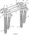
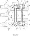
図9〜図13に例示された第2実施形態では、このシステムは第1実施形態のシステムにきわめてよく似ている。しかしながら、それは、細長い第2連結ロッド3、すなわち断面円形の副ロッドの存在によって、また、この第2ロッドを収容するための連結具6の適合によって、識別される。リング13は第1ロッドすなわち主ロッド2に収容される。
【0052】
2つの連結ロッド2,3のそれぞれには、輪郭の描かれた直線形状があり、その輪郭はここでは円形である。副ロッド3には、その長手軸に直角であって、主ロッド2の直径よりも小さい直径の備わった断面がある。主ロッド2にはたとえば6ミリメートルの直径が備わっている。副ロッド3の直径はたとえば、主ロッド2の直径の30パーセント〜80パーセントである。このような小さい直径によって、外科医は、手術の施される脊椎におけるレベルの曲率に対応している副ロッド3の曲率を選ぶことができる。これに対して、リング13によれば、2つの連結具6の相対角度位置決めが可能であるので、主ロッド2は曲げる必要がない。したがって、きわめて活発であるようにするために、実質的な直径を有することができる。
【0053】
連結具の分岐部16にはそれぞれ、互いに対向した分岐部の面に形成された円筒状の凹所あるいは顎部74がある。凹所74には、互いに対向して伸びるとともに、互いに平行であって対称平面Sに垂直である軸が備わっている。
【0054】
上方分岐部16では、凹所74は、オリフィス30が一方で面18,20の間に介在し他方で凹所74に介在するように、分岐部の自由端で延びている。下方分岐部16では、凹所74は、張出部分50の起点で、2つのオリフィス30および52の間に延びている。その凹所74は、その端部60に係合するために、オリフィス52に隣接している。
【0055】
副ロッド3は、対称の平面Sに垂直な連結具に関する独特の角度位置において下方分岐部16の凹所74に収容されるように意図されている。2つの分岐部16が互いの方向へ締め付けられるとき、上方分岐部の凹所74は副ロッド3に当接する。したがって、副ロッド3は2つの凹所のそれぞれに表面接触しており、2つの凹所は連結具6に対する副ロッド3の摩擦緊結を行い、それによって、互いに堅固に固定するためのものである。
【0056】
副ロッド3は、副ねじ12がオリフィス52の中に導入された後に、下方分岐部の凹所74に位置する。下方分岐部の凹所74の位置は、その副ロッド3がその後に連結具とオリフィス52からの出口とから離脱のために副ねじ12の頭部の軌跡を延びるような位置である。したがって、副ロッド3が連結具にいったん固定されると、その副ねじ12はもはや、その連結具から分離されることはない。
【0057】
連結具の上方分岐部16には、その自由端に切欠76が形成されている。この切欠76は、隣接する凹所74に係合し、かつ、上方分岐部によって占められた空間にもかかわらず、道具によって副ねじ12の処理を容易にする。
【0058】
第2実施形態に係るシステムは、第1実施形態のシステムに同様の方法で嵌合される。主ねじ8および副ねじ12の配置は変わることなく残る。
【0059】
隣接する2つの脊椎骨72に装備が施された後に、主ロッド2が連結具6のリング13の中に配置されるとともに、このロッド2に対するそれぞれの半組立体4の角度位置が調節される。次に、副ロッド3は、それが脊椎の対応レベルのために必要な曲率を得るためにまず手で曲げられた後に、連結具6の凹所74の中へ導入される。間違いがあった場合には、このロッド3は、その曲率を正すために取り外して、その後に定位置へ戻すことができる。図9には、分岐部を締め付ける前のシステムが示されている。最終締付は、主ねじ8の中に挿入されかつそれによって2つの分岐部16を互いの方へ締め付けるために連結具6を圧縮する締付用ねじ10に基づいて行われる。この締付の際に、締付力はまず、上方分岐部の凹所74が副ロッド3に当接するまで、リング13を介して主ロッド2の上に指し向けられる。その後、その締付力は2つのロッド2,3の上に分布する。したがって、主ねじ8と締付用ねじ10とを組み合わせることによるレベルでの反作用は、これらとほぼ同軸である。
【0060】
このシステムが定位置にあるときには、少なくとも2つある連結具6はそれぞれ、同一の主ロッドおよび副ロッドに一体にかつ同時に固定されている。
【0061】
第1ねじ8と締付用ねじ10との結合に関連した特性は、張出部分50および第2ねじ12の存在とは独立して満たすことができるであろう。
【0062】
あまり好都合ではないが、張り出した分岐部は脊椎骨から最も遠いように意図されているものであってもよい。
【0063】
連結具における2つの脊椎骨ねじの存在に関連した特性は、主ロッドおよび副ロッドの存在に関連したものとは独立して満たすことができるであろう。そして、逆も同様である。
【図面の簡単な説明】
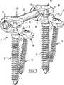
【図1】 図1は、この発明の第1実施形態に係るシステムの斜視図である。
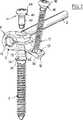
【図2】 図2は、図1におけるシステムの一部分解斜視図である。
【図3】 図3は、図1におけるシステムの1つの連結具を上方から示している斜視図である。
【図4】 図4は、図1におけるシステムの1つの連結具を下方から示している斜視図である。
【図5】 図5は、図1におけるシステムのリングの、半分正面・半分軸断面図である。
【図6】 図6は、ロッドを収容するための、図3における連結具の、一部上面・一部断面図である。
【図7】 図7は、主ねじの頭部を示している部分斜視図である。
【図8】 図8は、脊椎骨に固定された、図1のシステムを示している。
【図9】 図9は、この発明の第2実施形態に係るシステムの斜視図である。
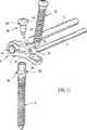
【図10】 図10は、図9におけるシステムの一部分解斜視図である。
【図11】 図11は、図9におけるシステムの1つの連結具を上方から示している斜視図である。
【図12】 図12は、図9におけるシステムの1つの連結具を下方から示している斜視図である。
【図13】 図13は、脊椎骨に固定された、図9のシステムを示している。[0001]
The present invention relates to a vertebral joint system, and more particularly to a vertebral joint system for anterior fixation.
[0002]
A vertebra joint system for anterior fixation in which the connecting element is formed by a plate-like body is known, and a vertebra joint system in which the connecting element is formed by a rod-like body is also known. Plate-based systems are bulky and difficult to use when used all through the endoscope path. Moreover, they can only be used for simple spinal resection on a single vertebra or possibly two vertebrae due to limited dimensions (length). It is impossible to treat scoliosis with this type of graft. Finally, these plates are difficult to adapt to the shape of the vertebrae to which they are fixed. Furthermore, rod-based systems usually have fairly bulky connectors and may not necessarily be used through the endoscope path.
[0003]
A vertebral joint device is also known from the specification of French patent application FR-2,731,344, which corresponds to international patent application WO-96 / 27340, in which two devices can be fastened with connecting rods. Bifurcated connectors are provided so that these bifurcations can be screwed onto the vertebral pedicle screws. However, although this connector is well adapted for posterior fixation of the spine at the vertebral pedicle, it cannot guarantee sufficient stability for the purpose of anterior fixation of the spine.
[0004]
One object of the present invention is the different types of vertebral joint systems that are adapted for anterior fixation, are easy to attach, ensure good stability in the spine and are interchangeably attached through the endoscopic pathway Is to make it available.
[0005]
To achieve this object, the present invention includes an elongateconnecting rod , a vertebral screw, and two branches that can clamp theconnecting rod between them, at least thelower branch being A vertebral joint system comprising a connector capable of screwing onto a vertebral screw, the system comprising a second vertebral screw, wherein thelower bifurcation can be screwed onto the second vertebral screw A vertebral joint system is provided.
[0006]
Thus, the connector can be reduced in bulk so that it can be put in place from the normal path or the path of the endoscope. Furthermore, fixing the connector to the vertebrae with two screws allows an accurate, stable and reliable positioning of theconnector and thus theconnecting rod . This connector can be easily connected to theconnecting rod andvertebral screw. These advantages make this connector particularly well suited for anterior fixation of the spine. This connector will preferably be a single piece.
[0007]
Preferably, the overhang has anorifice for receiving a second vertebral screw.
[0008]
This overhang preferably has a spherical recess at one end of anorifice intended to be remote from the vertebra.
[0009]
This is why the angle of the secondvertebral screw relative to the connector can be adjusted to better adapt the system to the vertebral morphology.
[0010]
Preferably, one bifurcation intended to be remote from the vertebra has anorifice for receiving the firstvertebral screw, and one end of theorifice intended to be remote from the vertebra has a spherical recess.
[0011]
This is why the angle of the firstvertebral screw relative to the connector can be adjusted to better adapt the system to the vertebral morphology.
[0012]
The overhanging branch is preferably bendable by hand, in particular using tools.
[0013]
This is why the shape of the connector can be adapted to the shape of the vertebra and the connector can be located very close to the vertebra.
[0014]
The firstvertebral screw can be clearly distinguished from the head and adjacent to the vertebra so that the rotation of the firstvertebral screw prevents the coupling from moving. A flange that can cooperate with one of the intended branches is included.
[0015]
Thus, once installed, positioning of the other elements is facilitated and the attached system is finally tightened prior to securing the coupling against the firstvertebral screw. Before, it becomes possible to perform all position corrections of this system.
[0016]
It is preferable that the flange portion has a surface, particularly a conical surface, which can be fixed so as not to move the connector by friction.
[0017]
The firstvertebral screw has a threaded orifice, and the system can be configured with a screw-nut connection to the orifice and is intended to be remote from the vertebra to tighten the bifurcation. Preferably, a clamping screw is provided that can receive one of the branches.
[0018]
This is why the firstvertebral screw, the connector and the secondvertebral screw can be fitted first, and immediately thereafter the clamping screw can be attached to proceed with tightening the assembly.
[0019]
The system is preferably provided with a ring that can be fitted to the rod and can be accommodated between the bifurcations, the coupling and the ring before the bifurcation is tightened. It is preferably designed so that the orientation of the rod can be adjusted in two planes perpendicular to each other.
[0020]
The two branches preferably form part of a single component that can be elastically deformed so that they are closed towards each other because of the branches.
[0021]
The connector is preferably one that can be secured to the vertebral screw and its firstconnecting rod by choosing the angular position of the firstconnecting rod relative to theconnector .
[0022]
It has also been found that the device in the specification of the French patent application FR-2,731,344 does not provide sufficient rigidity for anterior fixation of the spine.
[0023]
Accordingly, a secondary object of the present invention is to provide a system that is suitable for forward fixation and in which a particularly high degree of rigidity is guaranteed.
[0024]
In order to achieve such an object, the system is preferably provided with an elongated secondconnecting rod , and the connecting device can be fixed to twoconnecting rods simultaneously.
[0025]
This is why the presence of the twoconnecting rods increases the volume of its various components without complicating the assembly (makes mounting compatible via the endoscope path compatible). The system is very stiff, while still maintaining the possibility of adjusting the angular position of the coupler relative to the firstconnecting rod . The system according to the invention does not require the same bending of the twoconnecting rods . Furthermore, the number of couplers can remain small.
[0026]
The system is preferably designed such that the secondconnecting rod can be secured to the connector only at a single angular position relative to the connector.
[0027]
For this reason, the relative angular position of the fixture fixed to the shape of the secondconnecting rod is determined. This angular position can therefore be preselected at the time of manufacture or preferably during surgical intervention, depending on the conventional curvature applied to theconnecting rod .
[0028]
The secondconnecting rod is preferably less resistant to bending than the firstconnecting rod .
[0029]
Therefore, the firstconnecting rod mainly has a function of guaranteeing the support of the connecting tool, and the secondconnecting rod mainly has a function of guaranteeing the relative angle positioning of the connecting tool.
[0030]
It is preferable that the branch portion is capable of simultaneously tightening twoconnecting rods .
[0031]
The system is preferably designed such that when the secondconnecting rod is secured to the connector, the secondconnecting rod extends the locus of the second vertebral screw for disengagement from theconnector .
[0032]
This is why the secondvertebral screw is prevented from appearing at an inconvenient time.
[0033]
The system is provided with a second connector, and preferably the two connectors can each be fixed simultaneously to each of the twoconnecting rods .
[0034]
This system is preferably intended to be fixed in front of the spine.
[0035]
The invention also includes two branches that can tighten the elongatedconnecting rod , at least one of thelower branches has anorifice that can be screwed onto a vertebral screw, and thelower branch has a firstbranch . It provides a connector for a vertebral joint system that has an overhang with anorifice that can be threaded onto a vertebral screw.
This coupling is adapted to form part of the system according to the invention.
[0036]
Other features and advantages of the invention will become more apparent from the following description of two preferred embodiments given by way of non-limiting example.
[0037]
1 to 8, the system according to the present invention comprises, in a first embodiment, an elongated connecting
[0038]
According to FIGS. 3 and 4, the
[0039]
The
[0040]
Each
[0041]
For clarity, one
[0042]
The
[0043]
The
[0044]
Some characteristics of the
[0045]
The
[0046]
In an alternative embodiment, the
[0047]
In this example, the
[0048]
Such an apparatus is attached by the following method as shown in FIG. After exposing the damaged
[0049]
Thereafter, the
[0050]
After two
[0051]
In the second embodiment illustrated in FIGS. 9-13, this system is very similar to the system of the first embodiment. However, it is identified by the presence of an elongated second
[0052]
Each of the two connecting
[0053]
Each
[0054]
In the
[0055]
The
[0056]
The
[0057]
A
[0058]
The system according to the second embodiment is fitted to the system according to the first embodiment in the same manner. The arrangement of the
[0059]
After the two
[0060]
When the system is in place, at least two
[0061]
Properties associated with the connection of the
[0062]
Although not very convenient, the overhanging bifurcation may be intended to be furthest away from the vertebra.
[0063]
The properties associated with the presence of the two vertebral screws in the connector could be satisfied independently of those associated with the presence of the primary and secondary rods. And vice versa.
[Brief description of the drawings]
FIG. 1 is a perspective view of a system according to a first embodiment of the present invention.
FIG. 2 is a partially exploded perspective view of the system shown in FIG.
FIG. 3 is a perspective view showing one connector of the system in FIG. 1 from above.
FIG. 4 is a perspective view showing one connector of the system in FIG. 1 from below.
FIG. 5 is a half front and half axis cross-sectional view of the ring of the system in FIG.
6 is a partial top view and a partial cross-sectional view of the coupler in FIG. 3 for housing a rod. FIG.
FIG. 7 is a partial perspective view showing the head of the main screw.
FIG. 8 shows the system of FIG. 1 secured to a vertebra.
FIG. 9 is a perspective view of a system according to a second embodiment of the present invention.
10 is a partially exploded perspective view of the system in FIG. 9. FIG.
FIG. 11 is a perspective view showing one connector of the system in FIG. 9 from above.
FIG. 12 is a perspective view showing one connector of the system of FIG. 9 from below.
FIG. 13 shows the system of FIG. 9 secured to a vertebra.
Claims (18)
Translated fromJapanese第1脊椎骨ねじ(8)と第2脊椎骨ねじ(12)と、
前記第1連結ロッド(2)と第2連結ロッド(3)をそれらの間に締め付けることができる2つの分岐部(16)を有する連結具(6)とを有し、
前記分岐部(16)の少なくとも一方は前記第1脊椎骨ねじ(8)および第2脊椎骨ねじ(12)と係合することができ、前記連結具(6)は前記二つの分岐部(16)の接続部で前記第1連結ロッド(2)を固定し前記二つの分岐部(16)の接続部から所定の距離のところで前記第2連結ロッド(3)を固定し、前記第1脊椎骨ねじ(8)は前記第1連結ロッド(2)と第2連結ロッド(3)の間に配置され、前記第2脊椎骨ねじ(12)は前記第1連結ロッド(2)と第2連結ロッド(3)の外側の前記連結具(6)の分岐部(16)の自由端側に配置される、ことを特徴とする前方固定のための脊椎骨接合システム。An elongated first connecting rod (2) and a second connecting rod (3);
A first vertebral screw (8) and a second vertebral screw (12);
A connector (6) having two branches (16) capable of clamping the first connecting rod (2) and the second connecting rod (3) between them;
At least one of the bifurcation (16) can engage with the first vertebral screw (8) and the second vertebral screw (12), and theconnector (6) can beconnected to the two bifurcations (16). The first connecting rod (2) is fixed by a connecting portion, the second connecting rod (3) is fixed at a predetermined distance from the connecting portion of the two branch portions (16), and the first vertebral screw (8 ) Is disposed between the first connecting rod (2) and the second connecting rod (3), and the second vertebral screw (12) is connected to the first connecting rod (2) and the second connecting rod (3). A vertebral joint system for anterior fixation, characterized in that it is arranged onthe free end side of the bifurcation (16) of the outerconnector (6) .
Applications Claiming Priority (5)
| Application Number | Priority Date | Filing Date | Title |
|---|---|---|---|
| FR9805387AFR2778086B1 (en) | 1998-04-29 | 1998-04-29 | SPINAL OSTEOSYNTHESIS SYSTEM FOR ANTERIOR FASTENING |
| FR98/05387 | 1998-04-29 | ||
| FR9812662AFR2784282B1 (en) | 1998-10-09 | 1998-10-09 | SPINAL OSTEOSYNTHESIS SYSTEM WITH IMPROVED RIGIDITY |
| FR98/12662 | 1998-10-09 | ||
| PCT/FR1999/001019WO1999055246A1 (en) | 1998-04-29 | 1999-04-29 | Backbone osteosynthesis system for anterior fixing |
Publications (2)
| Publication Number | Publication Date |
|---|---|
| JP2002512839A JP2002512839A (en) | 2002-05-08 |
| JP4245806B2true JP4245806B2 (en) | 2009-04-02 |
Family
ID=26234298
Family Applications (2)
| Application Number | Title | Priority Date | Filing Date |
|---|---|---|---|
| JP2000545454AExpired - Fee RelatedJP4245806B2 (en) | 1998-04-29 | 1999-04-29 | Vertebral osteosynthesis system for anterior fixation |
| JP2000545455AExpired - Fee RelatedJP4245807B2 (en) | 1998-04-29 | 1999-04-29 | Vertebral joint system with clamping means, especially for anterior fixation |
Family Applications After (1)
| Application Number | Title | Priority Date | Filing Date |
|---|---|---|---|
| JP2000545455AExpired - Fee RelatedJP4245807B2 (en) | 1998-04-29 | 1999-04-29 | Vertebral joint system with clamping means, especially for anterior fixation |
Country Status (10)
| Country | Link |
|---|---|
| US (4) | US6569164B1 (en) |
| EP (2) | EP1075223B1 (en) |
| JP (2) | JP4245806B2 (en) |
| KR (2) | KR20010043166A (en) |
| AT (2) | ATE233521T1 (en) |
| AU (2) | AU762937B2 (en) |
| CA (2) | CA2330705A1 (en) |
| DE (3) | DE69905707T2 (en) |
| ES (1) | ES2155427T3 (en) |
| WO (2) | WO1999055246A1 (en) |
Families Citing this family (208)
| Publication number | Priority date | Publication date | Assignee | Title |
|---|---|---|---|---|
| US6206922B1 (en)* | 1995-03-27 | 2001-03-27 | Sdgi Holdings, Inc. | Methods and instruments for interbody fusion |
| CA2330705A1 (en)* | 1998-04-29 | 1999-11-04 | Dimso (Distribution Medicale Du Sud-Ouest) | Backbone osteosynthesis system for anterior fixing |
| US7094258B2 (en)* | 1999-08-18 | 2006-08-22 | Intrinsic Therapeutics, Inc. | Methods of reinforcing an annulus fibrosis |
| US7972337B2 (en) | 2005-12-28 | 2011-07-05 | Intrinsic Therapeutics, Inc. | Devices and methods for bone anchoring |
| US7717961B2 (en) | 1999-08-18 | 2010-05-18 | Intrinsic Therapeutics, Inc. | Apparatus delivery in an intervertebral disc |
| US8323341B2 (en) | 2007-09-07 | 2012-12-04 | Intrinsic Therapeutics, Inc. | Impaction grafting for vertebral fusion |
| CA2425951C (en)* | 1999-08-18 | 2008-09-16 | Intrinsic Therapeutics, Inc. | Devices and method for nucleus pulposus augmentation and retention |
| US7998213B2 (en) | 1999-08-18 | 2011-08-16 | Intrinsic Therapeutics, Inc. | Intervertebral disc herniation repair |
| EP1624832A4 (en) | 1999-08-18 | 2008-12-24 | Intrinsic Therapeutics Inc | Devices and method for augmenting a vertebral disc nucleus |
| ATE285207T1 (en)* | 1999-10-22 | 2005-01-15 | Archus Orthopedics Inc | FACET ARTHROPLASTY DEVICES |
| JP3383257B2 (en) | 2000-03-10 | 2003-03-04 | 株式会社ロバート・リード商会 | Rod fixing device |
| AU2001280476B2 (en) | 2000-06-30 | 2005-11-24 | Stephen Ritland | Polyaxial connection device and method |
| US7166073B2 (en) | 2000-09-29 | 2007-01-23 | Stephen Ritland | Method and device for microsurgical intermuscular spinal surgery |
| US6692434B2 (en) | 2000-09-29 | 2004-02-17 | Stephen Ritland | Method and device for retractor for microsurgical intermuscular lumbar arthrodesis |
| US6626906B1 (en)* | 2000-10-23 | 2003-09-30 | Sdgi Holdings, Inc. | Multi-planar adjustable connector |
| US7651516B2 (en)* | 2000-12-01 | 2010-01-26 | Spinevision S.A. | Connection assembly for the field of spinal osteosynthesis and method for using at least one such assembly |
| US6702817B2 (en)* | 2001-01-19 | 2004-03-09 | Aesculap Ag & Co. Kg | Locking mechanism for a bone screw |
| FR2821131B1 (en)* | 2001-02-22 | 2003-12-12 | Spine Next Sa | FASTENING SCREW |
| DE60238997D1 (en) | 2001-09-28 | 2011-03-03 | Stephen Ritland | CHROME OR HOOKS |
| FR2831420B1 (en)* | 2001-10-30 | 2004-07-16 | Vitatech | APPARATUS FOR HOLDING THE SPIN WITH JOINTING ASSEMBLY |
| ATE476930T1 (en) | 2002-02-20 | 2010-08-15 | Stephen Ritland | DEVICE FOR CONNECTING HAND SCREWS |
| FR2836368B1 (en)* | 2002-02-25 | 2005-01-14 | Spine Next Sa | SEQUENTIAL LINK DEVICE |
| US6966910B2 (en)* | 2002-04-05 | 2005-11-22 | Stephen Ritland | Dynamic fixation device and method of use |
| ATE552789T1 (en) | 2002-05-08 | 2012-04-15 | Stephen Ritland | DYNAMIC FIXATION DEVICE |
| FR2842093B1 (en)* | 2002-07-12 | 2005-04-15 | Scient X | BONE ANCHORING DEVICE WITH SPHERICAL JOINT |
| US20040015166A1 (en)* | 2002-07-22 | 2004-01-22 | Gorek Josef E. | System and method for stabilizing the spine by securing spine stabilization rods in crossed disposition |
| FR2842724B1 (en)* | 2002-07-23 | 2005-05-27 | Spine Next Sa | VERTEBRAL FASTENING SYSTEM |
| EP1562499B1 (en)* | 2002-09-04 | 2006-04-26 | Aesculap AG & Co. KG | Orthopedic fixation device |
| US7615070B2 (en)* | 2002-10-11 | 2009-11-10 | Spineco, Inc. | Electro-stimulation and medical delivery device |
| US20040111088A1 (en)* | 2002-12-06 | 2004-06-10 | Picetti George D. | Multi-rod bone attachment member |
| EP1596738A4 (en)* | 2003-02-25 | 2010-01-20 | Stephen Ritland | Adjustable rod and connector device and method of use |
| WO2004110247A2 (en) | 2003-05-22 | 2004-12-23 | Stephen Ritland | Intermuscular guide for retractor insertion and method of use |
| US7951176B2 (en) | 2003-05-30 | 2011-05-31 | Synthes Usa, Llc | Bone plate |
| US7270665B2 (en)* | 2003-06-11 | 2007-09-18 | Sdgi Holdings, Inc. | Variable offset spinal fixation system |
| DE20321551U1 (en) | 2003-08-26 | 2007-12-27 | Synthes Gmbh | bone plate |
| US11259851B2 (en) | 2003-08-26 | 2022-03-01 | DePuy Synthes Products, Inc. | Bone plate |
| US20050049595A1 (en) | 2003-09-03 | 2005-03-03 | Suh Sean S. | Track-plate carriage system |
| US7909860B2 (en) | 2003-09-03 | 2011-03-22 | Synthes Usa, Llc | Bone plate with captive clips |
| CA2537761A1 (en)* | 2003-09-04 | 2005-03-17 | Texas Scottish Rite Hospital For Children | Method for the correction of spinal deformities using rod-plates anterior system |
| ES2295708T3 (en)* | 2003-09-08 | 2008-04-16 | Synthes Gmbh | DEVICE FOR OSEA FIXATION. |
| DE20314297U1 (en)* | 2003-09-12 | 2003-11-20 | AlloCon GmbH, 42929 Wermelskirchen | bone screw |
| US8070785B2 (en) | 2003-09-16 | 2011-12-06 | Spineco, Inc. | Bone anchor prosthesis and system |
| DE50311436D1 (en)* | 2003-10-30 | 2009-05-28 | Synthes Gmbh | BONE PLATE |
| US7722650B2 (en)* | 2003-11-14 | 2010-05-25 | Ashman Richard B | Variable angle spinal implant connection assembly |
| US11291484B2 (en) | 2004-01-26 | 2022-04-05 | DePuy Synthes Products, Inc. | Highly-versatile variable-angle bone plate system |
| US7637928B2 (en)* | 2004-01-26 | 2009-12-29 | Synthes Usa, Llc | Variable angle locked bone fixation system |
| US8574268B2 (en)* | 2004-01-26 | 2013-11-05 | DePuy Synthes Product, LLC | Highly-versatile variable-angle bone plate system |
| US20050182317A1 (en)* | 2004-01-29 | 2005-08-18 | Haddad Souheil F. | Method and apparatus for locating medical devices in tissue |
| US7819902B2 (en) | 2004-02-27 | 2010-10-26 | Custom Spine, Inc. | Medialised rod pedicle screw assembly |
| US7892257B2 (en) | 2004-02-27 | 2011-02-22 | Custom Spine, Inc. | Spring loaded, load sharing polyaxial pedicle screw assembly and method |
| US7862594B2 (en) | 2004-02-27 | 2011-01-04 | Custom Spine, Inc. | Polyaxial pedicle screw assembly |
| US7163539B2 (en) | 2004-02-27 | 2007-01-16 | Custom Spine, Inc. | Biased angle polyaxial pedicle screw assembly |
| WO2005096973A1 (en)* | 2004-04-08 | 2005-10-20 | Tresona Instrument Ab | Device for correcting and stabilising a scoliosis curvature |
| US7914556B2 (en)* | 2005-03-02 | 2011-03-29 | Gmedelaware 2 Llc | Arthroplasty revision system and method |
| US7901435B2 (en)* | 2004-05-28 | 2011-03-08 | Depuy Spine, Inc. | Anchoring systems and methods for correcting spinal deformities |
| US8034085B2 (en)* | 2004-05-28 | 2011-10-11 | Depuy Spine, Inc. | Non-fusion spinal correction systems and methods |
| US8114158B2 (en) | 2004-08-03 | 2012-02-14 | Kspine, Inc. | Facet device and method |
| DE202004020396U1 (en) | 2004-08-12 | 2005-07-07 | Columbus Trading-Partners Pos und Brendel GbR (vertretungsberechtigte Gesellschafter Karin Brendel, 95503 Hummeltal und Bohumila Pos, 95445 Bayreuth) | Child seat for motor vehicles |
| CA2580101A1 (en)* | 2004-09-14 | 2006-03-23 | Spineco, Inc. | Implant device |
| US7455639B2 (en) | 2004-09-20 | 2008-11-25 | Stephen Ritland | Opposing parallel bladed retractor and method of use |
| US7766940B2 (en) | 2004-12-30 | 2010-08-03 | Depuy Spine, Inc. | Posterior stabilization system |
| US20060084976A1 (en) | 2004-09-30 | 2006-04-20 | Depuy Spine, Inc. | Posterior stabilization systems and methods |
| US8092496B2 (en) | 2004-09-30 | 2012-01-10 | Depuy Spine, Inc. | Methods and devices for posterior stabilization |
| US7896906B2 (en) | 2004-12-30 | 2011-03-01 | Depuy Spine, Inc. | Artificial facet joint |
| US20060095037A1 (en)* | 2004-10-29 | 2006-05-04 | Jones Bryan S | Connector assemblies for connecting a bone anchor to a fixation element |
| WO2006096351A1 (en)* | 2005-03-03 | 2006-09-14 | Accelerated Innovation, Llc | Spinal stabilization using bone anchor and anchor seat with tangential locking feature |
| WO2006096381A2 (en)* | 2005-03-03 | 2006-09-14 | Accelerated Innovation Llc | Spinal stabilization using bone anchor seat and cross coupling with improved locking feature |
| ES2556111T3 (en)* | 2005-04-08 | 2016-01-13 | Paradigm Spine, Llc | Interspinous vertebral and lumbosacral stabilization devices |
| US9942511B2 (en) | 2005-10-31 | 2018-04-10 | Invention Science Fund I, Llc | Preservation/degradation of video/audio aspects of a data stream |
| US7678112B2 (en)* | 2005-04-26 | 2010-03-16 | Warsaw Orthopedic, Inc. | Open dorsal adjusting connector |
| US7608081B2 (en)* | 2005-05-23 | 2009-10-27 | Custom Spine, Inc. | Rod reducer |
| CN101180522A (en)* | 2005-05-23 | 2008-05-14 | 亚米良寿公司 | Method and apparatus for measuring brightness of light emitting body |
| JP4988735B2 (en) | 2005-07-19 | 2012-08-01 | リットランド、ステファン | Rod extension for elongating fusion structures |
| US7628799B2 (en) | 2005-08-23 | 2009-12-08 | Aesculap Ag & Co. Kg | Rod to rod connector |
| DE102005044532A1 (en)* | 2005-09-16 | 2007-04-05 | Ulrich Gmbh & Co. Kg | Ventral plate |
| FR2890850B1 (en) | 2005-09-20 | 2009-04-17 | Abbott Spine Sa | VERTEBRAL FASTENING SYSTEM |
| FR2890851B1 (en) | 2005-09-21 | 2008-06-20 | Abbott Spine Sa | ANCILLARY TO TENSION A FLEXIBLE LINK. |
| US8075597B2 (en)* | 2005-09-23 | 2011-12-13 | Applied Orthopaedics Llc | Apparatus for retaining vertebrae |
| US7927359B2 (en)* | 2005-10-06 | 2011-04-19 | Paradigm Spine, Llc | Polyaxial screw |
| EP1931269A1 (en)* | 2005-10-07 | 2008-06-18 | Alphatec Spine, Inc. | Transverse rod connector |
| US7803174B2 (en)* | 2005-11-04 | 2010-09-28 | Warsaw Orthopedic, Inc. | Dorsal adjusting multi-rod connector |
| US8029546B2 (en)* | 2005-12-15 | 2011-10-04 | Warsaw Orthopedic, Inc. | Variable angle offset spinal connector assembly |
| US20070191844A1 (en)* | 2006-01-31 | 2007-08-16 | Sdgi Holdings, Inc. | In-series, dual locking mechanism device |
| US7585299B2 (en)* | 2006-02-17 | 2009-09-08 | Warsaw Orthopedic, Inc. | Dorsal adjusting spinal connector assembly |
| US8262696B2 (en)* | 2006-02-24 | 2012-09-11 | Medical Design, LLC | Multilevel facet/laminar fixation system |
| EP2012686B1 (en)* | 2006-04-18 | 2013-10-02 | Joseph Nicholas Logan | Spinal rod system |
| US7794501B2 (en)* | 2006-04-27 | 2010-09-14 | Wasaw Orthopedic, Inc. | Expandable intervertebral spacers and methods of use |
| US8361129B2 (en)* | 2006-04-28 | 2013-01-29 | Depuy Spine, Inc. | Large diameter bone anchor assembly |
| US20080015576A1 (en)* | 2006-04-28 | 2008-01-17 | Whipple Dale E | Large diameter bone anchor assembly |
| US20080015596A1 (en)* | 2006-04-28 | 2008-01-17 | Whipple Dale E | Large diameter multiple piece bone anchor assembly |
| US8133262B2 (en)* | 2006-04-28 | 2012-03-13 | Depuy Spine, Inc. | Large diameter bone anchor assembly |
| US20080058808A1 (en) | 2006-06-14 | 2008-03-06 | Spartek Medical, Inc. | Implant system and method to treat degenerative disorders of the spine |
| US7959564B2 (en) | 2006-07-08 | 2011-06-14 | Stephen Ritland | Pedicle seeker and retractor, and methods of use |
| EP2047813A1 (en) | 2007-10-11 | 2009-04-15 | Abbott Spine | Bone fixing system and method of use |
| JP2010503498A (en)* | 2006-09-18 | 2010-02-04 | ウォーソー・オーソペディック・インコーポレーテッド | Orthopedic plate apparatus |
| US8672983B2 (en)* | 2006-09-18 | 2014-03-18 | Warsaw Orthopedic, Inc. | Orthopedic plate system |
| US20080086130A1 (en)* | 2006-10-06 | 2008-04-10 | Depuy Spine, Inc. | Torsionally stable fixation |
| US7744632B2 (en) | 2006-12-20 | 2010-06-29 | Aesculap Implant Systems, Inc. | Rod to rod connector |
| US8747445B2 (en) | 2007-01-15 | 2014-06-10 | Ebi, Llc | Spinal fixation device |
| WO2008128105A1 (en)* | 2007-04-12 | 2008-10-23 | Texas Scottish Rite Hospital For Children | Orthopedic fastener for stabilization and fixation |
| US8052722B2 (en) | 2007-06-05 | 2011-11-08 | Spartek Medical, Inc. | Dual deflection rod system for a dynamic stabilization and motion preservation spinal implantation system and method |
| US8048115B2 (en) | 2007-06-05 | 2011-11-01 | Spartek Medical, Inc. | Surgical tool and method for implantation of a dynamic bone anchor |
| US8114134B2 (en) | 2007-06-05 | 2012-02-14 | Spartek Medical, Inc. | Spinal prosthesis having a three bar linkage for motion preservation and dynamic stabilization of the spine |
| US8109970B2 (en) | 2007-06-05 | 2012-02-07 | Spartek Medical, Inc. | Deflection rod system with a deflection contouring shield for a spine implant and method |
| US8048123B2 (en) | 2007-06-05 | 2011-11-01 | Spartek Medical, Inc. | Spine implant with a deflection rod system and connecting linkages and method |
| US8083772B2 (en)* | 2007-06-05 | 2011-12-27 | Spartek Medical, Inc. | Dynamic spinal rod assembly and method for dynamic stabilization of the spine |
| US8048128B2 (en) | 2007-06-05 | 2011-11-01 | Spartek Medical, Inc. | Revision system and method for a dynamic stabilization and motion preservation spinal implantation system and method |
| US8021396B2 (en) | 2007-06-05 | 2011-09-20 | Spartek Medical, Inc. | Configurable dynamic spinal rod and method for dynamic stabilization of the spine |
| US8092501B2 (en) | 2007-06-05 | 2012-01-10 | Spartek Medical, Inc. | Dynamic spinal rod and method for dynamic stabilization of the spine |
| EP2155086B1 (en) | 2007-06-06 | 2016-05-04 | K2M, Inc. | Medical device to correct deformity |
| US20110196492A1 (en)* | 2007-09-07 | 2011-08-11 | Intrinsic Therapeutics, Inc. | Bone anchoring systems |
| US20090076550A1 (en)* | 2007-09-18 | 2009-03-19 | Ortho Development Corporation | Spinal fixation system connectors |
| FR2921248A1 (en)* | 2007-09-25 | 2009-03-27 | Abbott Spine Sa | DEVICE FOR TIGHTENING TWO PORTIONS OF A BRAID AND INTERVERTEBRAL IMPLANT COMPRISING A BILGE, A BRAID AND A SUCH TIGHTENING DEVICE |
| ATE536824T1 (en)* | 2007-10-23 | 2011-12-15 | Zimmer Spine | FASTENING DEVICES AND STABILIZATION SYSTEMS WITH THESE FASTENING DEVICES |
| US8128635B2 (en)* | 2007-10-23 | 2012-03-06 | Zimmer Spine S.A.S. | Bone fixation tensioning tool and method |
| WO2009055400A1 (en)* | 2007-10-23 | 2009-04-30 | K2M, Inc. | Polyaxial screw assembly |
| US9408641B2 (en)* | 2008-02-02 | 2016-08-09 | Globus Medical, Inc. | Spinal rod link reducer |
| US9345517B2 (en) | 2008-02-02 | 2016-05-24 | Globus Medical, Inc. | Pedicle screw having a removable rod coupling |
| US9579126B2 (en) | 2008-02-02 | 2017-02-28 | Globus Medical, Inc. | Spinal rod link reducer |
| WO2009097623A2 (en)* | 2008-02-02 | 2009-08-06 | Texas Scottish Rite Hospital For Children | Pedicle screw |
| US8097024B2 (en) | 2008-02-26 | 2012-01-17 | Spartek Medical, Inc. | Load-sharing bone anchor having a deflectable post and method for stabilization of the spine |
| US8083775B2 (en) | 2008-02-26 | 2011-12-27 | Spartek Medical, Inc. | Load-sharing bone anchor having a natural center of rotation and method for dynamic stabilization of the spine |
| US8007518B2 (en) | 2008-02-26 | 2011-08-30 | Spartek Medical, Inc. | Load-sharing component having a deflectable post and method for dynamic stabilization of the spine |
| US8048125B2 (en) | 2008-02-26 | 2011-11-01 | Spartek Medical, Inc. | Versatile offset polyaxial connector and method for dynamic stabilization of the spine |
| US8211155B2 (en) | 2008-02-26 | 2012-07-03 | Spartek Medical, Inc. | Load-sharing bone anchor having a durable compliant member and method for dynamic stabilization of the spine |
| US8057517B2 (en) | 2008-02-26 | 2011-11-15 | Spartek Medical, Inc. | Load-sharing component having a deflectable post and centering spring and method for dynamic stabilization of the spine |
| US8337536B2 (en) | 2008-02-26 | 2012-12-25 | Spartek Medical, Inc. | Load-sharing bone anchor having a deflectable post with a compliant ring and method for stabilization of the spine |
| US8267979B2 (en) | 2008-02-26 | 2012-09-18 | Spartek Medical, Inc. | Load-sharing bone anchor having a deflectable post and axial spring and method for dynamic stabilization of the spine |
| US8333792B2 (en) | 2008-02-26 | 2012-12-18 | Spartek Medical, Inc. | Load-sharing bone anchor having a deflectable post and method for dynamic stabilization of the spine |
| ATE515239T1 (en)* | 2008-04-24 | 2011-07-15 | Zimmer Spine | SYSTEM FOR STABILIZING AT LEAST ONE SECTION OF THE SPINE |
| EP2303163B1 (en)* | 2008-05-20 | 2011-11-23 | Zimmer Spine | System for stabilizing at least three vertebrae |
| EP2484300B1 (en)* | 2008-09-05 | 2015-05-20 | Biedermann Technologies GmbH & Co. KG | Stabilization device for bones, in particular for the spinal column |
| US20100087867A1 (en)* | 2008-10-03 | 2010-04-08 | Assaf Klein | Fastener assembly that fastens to pedicle screw |
| GB2465156B (en) | 2008-11-05 | 2012-09-26 | Dalmatic Lystrup As | Bone fixation system |
| GB2465335B (en)* | 2008-11-05 | 2012-08-15 | Dalmatic Lystrup As | Bone fixation device |
| US20100114171A1 (en)* | 2008-11-05 | 2010-05-06 | K2M, Inc. | Multi-planar spinal fixation assembly with locking element |
| US8828058B2 (en) | 2008-11-11 | 2014-09-09 | Kspine, Inc. | Growth directed vertebral fixation system with distractible connector(s) and apical control |
| WO2010059881A2 (en)* | 2008-11-19 | 2010-05-27 | Brett Babat | Bone fixation assembly |
| US9351767B2 (en)* | 2009-03-24 | 2016-05-31 | Life Spine, Inc. | Supplementary spinal fixation/stabilization apparatus with dynamic inter-vertebral connection |
| US8357182B2 (en) | 2009-03-26 | 2013-01-22 | Kspine, Inc. | Alignment system with longitudinal support features |
| US8109976B2 (en)* | 2009-05-21 | 2012-02-07 | Warsaw Orthopedic, Inc. | Systems and methods for vertebral stabilization |
| US20100305615A1 (en)* | 2009-05-29 | 2010-12-02 | Custom Spine, Inc. | Multi-level Polyaxial Screw Connection Mechanism |
| US8758346B2 (en)* | 2009-09-14 | 2014-06-24 | DePuy Synthes Products, LLC | Variable angle compression plate |
| US9168071B2 (en) | 2009-09-15 | 2015-10-27 | K2M, Inc. | Growth modulation system |
| US8568456B2 (en) | 2009-09-21 | 2013-10-29 | Globus Medical, Inc. | Transverse connector having a locking element for capturing multiple rods |
| US8361123B2 (en) | 2009-10-16 | 2013-01-29 | Depuy Spine, Inc. | Bone anchor assemblies and methods of manufacturing and use thereof |
| CN102695465A (en) | 2009-12-02 | 2012-09-26 | 斯帕泰克医疗股份有限公司 | Low profile spinal prosthesis incorporating a bone anchor having a deflectable post and a compound spinal rod |
| FR2954905B1 (en) | 2010-01-06 | 2012-12-28 | Implanet | DEVICE FOR FIXING VERTEBRAL |
| US8317834B2 (en)* | 2010-01-28 | 2012-11-27 | Warsaw Orthopedic, Inc. | Pre-assembled construct for insertion into a patient |
| WO2011106339A1 (en) | 2010-02-23 | 2011-09-01 | K2M, Inc. | Polyaxial bone screw assembly |
| US8758347B2 (en)* | 2010-03-19 | 2014-06-24 | Nextremity Solutions, Inc. | Dynamic bone plate |
| US10219842B2 (en)* | 2010-03-23 | 2019-03-05 | Scapa Flow, Llc | Cervical link system |
| EP2555696B1 (en)* | 2010-04-08 | 2017-07-26 | Globus Medical, Inc. | Jointed rod |
| US20110307015A1 (en) | 2010-06-10 | 2011-12-15 | Spartek Medical, Inc. | Adaptive spinal rod and methods for stabilization of the spine |
| US8777996B2 (en) | 2010-07-12 | 2014-07-15 | Globus Medical, Inc. | Interspinous ligament transverse connector |
| US8920471B2 (en) | 2010-07-12 | 2014-12-30 | K2M, Inc. | Transverse connector |
| EP2471476A1 (en)* | 2010-11-10 | 2012-07-04 | Zimmer Spine | Bone anchor |
| US9387013B1 (en) | 2011-03-01 | 2016-07-12 | Nuvasive, Inc. | Posterior cervical fixation system |
| US9247964B1 (en) | 2011-03-01 | 2016-02-02 | Nuasive, Inc. | Spinal Cross-connector |
| US8992579B1 (en)* | 2011-03-08 | 2015-03-31 | Nuvasive, Inc. | Lateral fixation constructs and related methods |
| JP6158176B2 (en) | 2011-06-03 | 2017-07-05 | ケイツーエム インコーポレイテッドK2M,Inc. | Spine correction system |
| US20130085534A1 (en)* | 2011-09-30 | 2013-04-04 | Nicolas Hainard | Connectors for a secondary bone anchor |
| US9468469B2 (en) | 2011-11-16 | 2016-10-18 | K2M, Inc. | Transverse coupler adjuster spinal correction systems and methods |
| US9451987B2 (en)* | 2011-11-16 | 2016-09-27 | K2M, Inc. | System and method for spinal correction |
| US9468468B2 (en) | 2011-11-16 | 2016-10-18 | K2M, Inc. | Transverse connector for spinal stabilization system |
| WO2014172632A2 (en) | 2011-11-16 | 2014-10-23 | Kspine, Inc. | Spinal correction and secondary stabilization |
| US8920472B2 (en) | 2011-11-16 | 2014-12-30 | Kspine, Inc. | Spinal correction and secondary stabilization |
| US8430916B1 (en) | 2012-02-07 | 2013-04-30 | Spartek Medical, Inc. | Spinal rod connectors, methods of use, and spinal prosthesis incorporating spinal rod connectors |
| US9060815B1 (en) | 2012-03-08 | 2015-06-23 | Nuvasive, Inc. | Systems and methods for performing spine surgery |
| FR2989264B1 (en)* | 2012-04-11 | 2014-05-09 | Medicrea International | MATERIAL OF VERTEBRAL OSTEOSYNTHESIS |
| US8828056B2 (en) | 2012-04-16 | 2014-09-09 | Aesculap Implant Systems, Llc | Rod to rod cross connector |
| US8771319B2 (en) | 2012-04-16 | 2014-07-08 | Aesculap Implant Systems, Llc | Rod to rod cross connector |
| US10405893B2 (en) | 2012-07-12 | 2019-09-10 | DePuy Synthes Products, Inc. | Device, kit and method for correction of spinal deformity |
| US9301782B2 (en) | 2012-09-04 | 2016-04-05 | Zimmer, Inc. | External fixation |
| US9924969B2 (en) | 2012-09-04 | 2018-03-27 | Zimmer, Inc. | External fixation |
| EP2724679A1 (en)* | 2012-10-23 | 2014-04-30 | Nexus Spine, L.L.C. | Transverse connector and related methods |
| KR101424128B1 (en) | 2012-12-28 | 2014-08-01 | 대구가톨릭대학교산학협력단 | External bone fixator |
| US8979898B2 (en) | 2013-02-20 | 2015-03-17 | K2M, Inc. | Iliosacral polyaxial screw |
| US9237907B2 (en) | 2013-03-05 | 2016-01-19 | Warsaw Orthopedic, Inc. | Spinal correction system and method |
| WO2014139085A1 (en)* | 2013-03-12 | 2014-09-18 | Hewlett-Packard Development Company, L.P. | Identifying transport-level encoded payloads |
| US9468471B2 (en) | 2013-09-17 | 2016-10-18 | K2M, Inc. | Transverse coupler adjuster spinal correction systems and methods |
| US9517089B1 (en) | 2013-10-08 | 2016-12-13 | Nuvasive, Inc. | Bone anchor with offset rod connector |
| FR3012032B1 (en) | 2013-10-18 | 2015-12-11 | Implanet | DEVICE AND SYSTEM FOR VERTICAL FASTENING FOR HOLDING A VERTEBRA ON A ROD, METHOD OF BLOCKING A LOOP WITH SUCH A DEVICE. |
| US9877755B2 (en) | 2014-03-17 | 2018-01-30 | Pega Medical, Inc. | Orthopedic apparatus for correcting rotational bone deformities and method for using the orthopedic apparatus |
| US9962187B2 (en) | 2014-08-11 | 2018-05-08 | Zimmer, Inc. | External fixation |
| US9579123B2 (en)* | 2014-09-19 | 2017-02-28 | Globus Medical, Inc. | Orthopedic stabilization devices and methods for installation thereof |
| US9649133B2 (en)* | 2014-11-11 | 2017-05-16 | Intrepid Orthopedics | Supplemental fixation screw |
| EP3280339A1 (en)* | 2015-04-07 | 2018-02-14 | K2M, Inc. | Spinal stabilization device, system, and method of use |
| US9763703B2 (en) | 2015-05-05 | 2017-09-19 | Degen Medical, Inc. | Cross connectors, kits, and methods |
| WO2016205128A2 (en) | 2015-06-17 | 2016-12-22 | Nathan Erickson | Ankle fixation system |
| US9968378B1 (en)* | 2015-07-22 | 2018-05-15 | University Of South Florida | Adaptation sphere saddle |
| HU5038U (en) | 2015-09-25 | 2019-07-29 | Pelle Gyoergy Dr | Bone fixation implant |
| US9962192B2 (en) | 2016-03-17 | 2018-05-08 | Medos International Sarl | Multipoint fixation implants |
| US10624686B2 (en) | 2016-09-08 | 2020-04-21 | DePuy Synthes Products, Inc. | Variable angel bone plate |
| US10905476B2 (en) | 2016-09-08 | 2021-02-02 | DePuy Synthes Products, Inc. | Variable angle bone plate |
| US10820930B2 (en) | 2016-09-08 | 2020-11-03 | DePuy Synthes Products, Inc. | Variable angle bone plate |
| US11026727B2 (en) | 2018-03-20 | 2021-06-08 | DePuy Synthes Products, Inc. | Bone plate with form-fitting variable-angle locking hole |
| US10898232B2 (en) | 2018-03-20 | 2021-01-26 | Medos International Sàrl | Multipoint fixation implants and related methods |
| US10772665B2 (en) | 2018-03-29 | 2020-09-15 | DePuy Synthes Products, Inc. | Locking structures for affixing bone anchors to a bone plate, and related systems and methods |
| US11013541B2 (en) | 2018-04-30 | 2021-05-25 | DePuy Synthes Products, Inc. | Threaded locking structures for affixing bone anchors to a bone plate, and related systems and methods |
| US10925651B2 (en) | 2018-12-21 | 2021-02-23 | DePuy Synthes Products, Inc. | Implant having locking holes with collection cavity for shavings |
| US10893894B2 (en) | 2019-04-24 | 2021-01-19 | Aesculap Implant Systems, Llc | Transverse coupling for surgical implant extensions |
| US11426210B2 (en) | 2019-09-25 | 2022-08-30 | Medos International Sàrl | Multipoint angled fixation implants for multiple screws and related methods |
| US11653953B2 (en) | 2019-10-11 | 2023-05-23 | Medos International Sarl | Implant receivers and connectors with grip grooves for rod fixation |
| EP4103083B1 (en) | 2020-02-14 | 2024-10-23 | Medos International Sàrl | Integrated multipoint fixation screw |
| US11707307B2 (en) | 2020-12-04 | 2023-07-25 | Globus Medical, Inc. | Systems and methods for treating rib fractures and osteotomies using implantation |
| US12102364B2 (en) | 2020-12-04 | 2024-10-01 | Globus Medical, Inc. | Systems and methods for treating rib fractures and osteotomies using implantation |
| AU2024232696A1 (en)* | 2023-03-06 | 2025-10-09 | Zimmer Biomet CMF and Thoracic, LLC | Pectus bar and stabilizer devices |
Family Cites Families (36)
| Publication number | Priority date | Publication date | Assignee | Title |
|---|---|---|---|---|
| FR2244446A1 (en) | 1973-09-21 | 1975-04-18 | Cotrel Yves | Traction device for scoliosis - tensioner rod clamped across vert. rods tensions vertebrae under max stress |
| US4289123A (en) | 1980-03-31 | 1981-09-15 | Dunn Harold K | Orthopedic appliance |
| US4987892A (en) | 1989-04-04 | 1991-01-29 | Krag Martin H | Spinal fixation device |
| FR2651992B1 (en) | 1989-09-18 | 1991-12-13 | Sofamor | IMPLANT FOR ANTERIOR DORSO-LUMBAR SPINE OSTEOSYNTHESIS FOR CORRECTION OF CYPHOSIS. |
| FR2658413B1 (en) | 1990-02-19 | 1997-01-03 | Sofamor | OSTEOSYNTHESIS DEVICE FOR THE CORRECTION OF SPINAL DEVIATIONS. |
| US5147380A (en)* | 1991-10-03 | 1992-09-15 | Cordis Corporation | Biopsy forceps device having improved locking means |
| FR2689750B1 (en) | 1992-04-10 | 1997-01-31 | Eurosurgical | BONE ANCHORING ELEMENT AND SPINAL OSTEOSYNTHESIS DEVICE INCORPORATING SUCH ELEMENTS. |
| ATE124238T1 (en) | 1992-05-18 | 1995-07-15 | Pina Vertriebs Ag | IMPLANT FOR THE SPINE. |
| US5324290A (en) | 1992-09-24 | 1994-06-28 | Danek Medical, Inc. | Anterior thoracolumbar plate |
| FR2697744B1 (en) | 1992-11-10 | 1995-03-03 | Fabrication Mat Orthopedique S | Spinal osteosynthesis instrumentation by the anterior route. |
| US5702395A (en)* | 1992-11-10 | 1997-12-30 | Sofamor S.N.C. | Spine osteosynthesis instrumentation for an anterior approach |
| US5306275A (en) | 1992-12-31 | 1994-04-26 | Bryan Donald W | Lumbar spine fixation apparatus and method |
| WO1994026194A1 (en)* | 1993-05-18 | 1994-11-24 | Schäfer Micomed GmbH | Holding device for use in bone surgery |
| US5628740A (en)* | 1993-12-23 | 1997-05-13 | Mullane; Thomas S. | Articulating toggle bolt bone screw |
| US5662652A (en) | 1994-04-28 | 1997-09-02 | Schafer Micomed Gmbh | Bone surgery holding apparatus |
| DE4433360C2 (en) | 1994-07-19 | 1996-12-12 | Schaefer Micomed Gmbh | Bone surgery holding device |
| DE9412744U1 (en)* | 1994-08-06 | 1995-12-07 | Schäfer micomed GmbH, 73614 Schorndorf | Bone surgery holding device |
| FR2724553B1 (en) | 1994-09-15 | 1996-12-20 | Tornier Sa | EXTERNAL OR INTERNAL FIXER FOR THE REPAIR OF FRACTURES OR ARTHROPLASTIES OF THE SKELETON |
| US6004322A (en)* | 1994-10-25 | 1999-12-21 | Sdgi Holdings, Inc. | Modular pedicle screw system |
| US5620443A (en)* | 1995-01-25 | 1997-04-15 | Danek Medical, Inc. | Anterior screw-rod connector |
| FR2731344B1 (en)* | 1995-03-06 | 1997-08-22 | Dimso Sa | SPINAL INSTRUMENTATION ESPECIALLY FOR A ROD |
| US5716355A (en)* | 1995-04-10 | 1998-02-10 | Sofamor Danek Group, Inc. | Transverse connection for spinal rods |
| US5613968A (en) | 1995-05-01 | 1997-03-25 | Lin; Chih-I | Universal pad fixation device for orthopedic surgery |
| US5683391A (en) | 1995-06-07 | 1997-11-04 | Danek Medical, Inc. | Anterior spinal instrumentation and method for implantation and revision |
| FR2743712B1 (en)* | 1996-01-19 | 1998-04-30 | Louis Rene | POSTERIOR VERTEBRAL OSTEOSYNTHESIS ANCHORING DEVICE |
| AU2655397A (en) | 1996-04-18 | 1997-11-07 | Jan-Erik Nilsson | Device and method for correcting and stabilising a deviating curvature of a spinal column |
| DE29712697U1 (en)* | 1997-07-18 | 1997-09-25 | ENDOTEC Vertriebs- und Beratungsgesellschaft für Medizintechnik mbH, 51399 Burscheid | Spinal fixator |
| US5964769A (en)* | 1997-08-26 | 1999-10-12 | Spinal Concepts, Inc. | Surgical cable system and method |
| EP0923908B1 (en)* | 1997-12-17 | 2003-04-23 | Robert Lange | Apparatus for stabilizing certain vertebrae of the spine |
| EP0933065A1 (en) | 1998-02-02 | 1999-08-04 | Sulzer Orthopädie AG | Pivotable attachment system for a bone screw |
| CA2330705A1 (en)* | 1998-04-29 | 1999-11-04 | Dimso (Distribution Medicale Du Sud-Ouest) | Backbone osteosynthesis system for anterior fixing |
| FR2780631B1 (en) | 1998-07-06 | 2000-09-29 | Dimso Sa | SPINAL OSTEOSYNTHESIS DEVICE FOR ANTERIOR FIXATION WITH PLATE |
| US6136002A (en)* | 1999-02-05 | 2000-10-24 | Industrial Technology Research Institute | Anterior spinal fixation system |
| DE19914232B4 (en)* | 1999-03-29 | 2012-08-30 | Signus Medizintechnik Gmbh | Device for stabilizing vertebral bodies of a spinal column |
| US6328739B1 (en)* | 1999-05-04 | 2001-12-11 | Industrial Technology Research Institute | Enhanced spine fixation apparatus |
| DE19944120B4 (en) | 1999-09-15 | 2008-08-28 | Ulrich Gmbh & Co. Kg | Bone screw for variable angle connection with a side member |
- 1999
- 1999-04-29CACA002330705Apatent/CA2330705A1/ennot_activeAbandoned
- 1999-04-29USUS09/674,207patent/US6569164B1/ennot_activeExpired - Fee Related
- 1999-04-29WOPCT/FR1999/001019patent/WO1999055246A1/enactiveIP Right Grant
- 1999-04-29KRKR1020007012084Apatent/KR20010043166A/ennot_activeWithdrawn
- 1999-04-29ATAT99916956Tpatent/ATE233521T1/ennot_activeIP Right Cessation
- 1999-04-29ESES99916956Tpatent/ES2155427T3/ennot_activeExpired - Lifetime
- 1999-04-29AUAU35257/99Apatent/AU762937B2/ennot_activeCeased
- 1999-04-29USUS09/674,196patent/US6565569B1/ennot_activeExpired - Fee Related
- 1999-04-29JPJP2000545454Apatent/JP4245806B2/ennot_activeExpired - Fee Related
- 1999-04-29EPEP99916955Apatent/EP1075223B1/ennot_activeExpired - Lifetime
- 1999-04-29AUAU35258/99Apatent/AU759236B2/ennot_activeCeased
- 1999-04-29ATAT99916955Tpatent/ATE309753T1/ennot_activeIP Right Cessation
- 1999-04-29CACA002330802Apatent/CA2330802A1/ennot_activeAbandoned
- 1999-04-29DEDE69905707Tpatent/DE69905707T2/ennot_activeExpired - Lifetime
- 1999-04-29DEDE69928389Tpatent/DE69928389T2/ennot_activeExpired - Lifetime
- 1999-04-29EPEP99916956Apatent/EP1075224B1/ennot_activeExpired - Lifetime
- 1999-04-29WOPCT/FR1999/001020patent/WO1999055247A1/ennot_activeApplication Discontinuation
- 1999-04-29JPJP2000545455Apatent/JP4245807B2/ennot_activeExpired - Fee Related
- 1999-04-29KRKR1020007012083Apatent/KR20010034836A/ennot_activeWithdrawn
- 1999-04-29DEDE1075224Tpatent/DE1075224T1/enactivePending
- 2003
- 2003-03-13USUS10/387,918patent/US7008423B2/ennot_activeExpired - Fee Related
- 2003-03-17USUS10/390,227patent/US6881215B2/ennot_activeExpired - Fee Related
Also Published As
| Publication number | Publication date |
|---|---|
| JP2002512839A (en) | 2002-05-08 |
| ES2155427T3 (en) | 2003-07-01 |
| US6565569B1 (en) | 2003-05-20 |
| AU3525799A (en) | 1999-11-16 |
| WO1999055247A1 (en) | 1999-11-04 |
| EP1075223A1 (en) | 2001-02-14 |
| US6569164B1 (en) | 2003-05-27 |
| US20030171752A1 (en) | 2003-09-11 |
| EP1075223B1 (en) | 2005-11-16 |
| JP2002512840A (en) | 2002-05-08 |
| EP1075224B1 (en) | 2003-03-05 |
| ATE233521T1 (en) | 2003-03-15 |
| ES2155427T1 (en) | 2001-05-16 |
| DE69928389T2 (en) | 2006-06-22 |
| AU3525899A (en) | 1999-11-16 |
| US20030187438A1 (en) | 2003-10-02 |
| US7008423B2 (en) | 2006-03-07 |
| WO1999055246A1 (en) | 1999-11-04 |
| US6881215B2 (en) | 2005-04-19 |
| JP4245807B2 (en) | 2009-04-02 |
| DE69905707D1 (en) | 2003-04-10 |
| DE1075224T1 (en) | 2001-10-11 |
| EP1075224A1 (en) | 2001-02-14 |
| DE69928389D1 (en) | 2005-12-22 |
| CA2330802A1 (en) | 1999-11-04 |
| CA2330705A1 (en) | 1999-11-04 |
| ATE309753T1 (en) | 2005-12-15 |
| KR20010034836A (en) | 2001-04-25 |
| AU762937B2 (en) | 2003-07-10 |
| KR20010043166A (en) | 2001-05-25 |
| DE69905707T2 (en) | 2003-11-06 |
| AU759236B2 (en) | 2003-04-10 |
Similar Documents
| Publication | Publication Date | Title |
|---|---|---|
| JP4245806B2 (en) | Vertebral osteosynthesis system for anterior fixation | |
| JP4254060B2 (en) | Stable vertebra joint system | |
| EP1109502B1 (en) | Variable angle spinal fixation system | |
| JP4907352B2 (en) | Connecting transformer connector for connecting spinal rods | |
| US8491642B2 (en) | Spinal transverse connector | |
| US7803174B2 (en) | Dorsal adjusting multi-rod connector | |
| US7648522B2 (en) | Bone fixation assembly and method | |
| EP1330196B1 (en) | Connector for spinal rod and vertebral anchor | |
| US6585738B1 (en) | Spinal osteosynthesis device for anterior fixation with plate | |
| US20050070899A1 (en) | Polyaxial bone screw with torqueless fastening | |
| US8795337B2 (en) | Apparatus for implementing a spinal fixation system with supplemental fixation | |
| CA2088961A1 (en) | Perpendicular rod connector for spinal fixation device | |
| EP1098601A1 (en) | Spinal osteosynthesis device | |
| KR19980702816A (en) | Bone Bonding Mechanism for Rod | |
| KR101990375B1 (en) | Hook type connector | |
| US20040059332A1 (en) | Anterior spinal anchor plate | |
| MXPA00010648A (en) | Backbone osteosynthesis system with clamping means in particular for anterior fixing | |
| HK1036745B (en) | Variable angle spinal fixation system |
Legal Events
| Date | Code | Title | Description |
|---|---|---|---|
| A621 | Written request for application examination | Free format text:JAPANESE INTERMEDIATE CODE: A621 Effective date:20050614 | |
| A131 | Notification of reasons for refusal | Free format text:JAPANESE INTERMEDIATE CODE: A131 Effective date:20070724 | |
| A601 | Written request for extension of time | Free format text:JAPANESE INTERMEDIATE CODE: A601 Effective date:20071024 | |
| A602 | Written permission of extension of time | Free format text:JAPANESE INTERMEDIATE CODE: A602 Effective date:20071031 | |
| A601 | Written request for extension of time | Free format text:JAPANESE INTERMEDIATE CODE: A601 Effective date:20071126 | |
| A602 | Written permission of extension of time | Free format text:JAPANESE INTERMEDIATE CODE: A602 Effective date:20071203 | |
| A601 | Written request for extension of time | Free format text:JAPANESE INTERMEDIATE CODE: A601 Effective date:20071225 | |
| A602 | Written permission of extension of time | Free format text:JAPANESE INTERMEDIATE CODE: A602 Effective date:20080107 | |
| A521 | Request for written amendment filed | Free format text:JAPANESE INTERMEDIATE CODE: A523 Effective date:20080124 | |
| A131 | Notification of reasons for refusal | Free format text:JAPANESE INTERMEDIATE CODE: A131 Effective date:20080711 | |
| A601 | Written request for extension of time | Free format text:JAPANESE INTERMEDIATE CODE: A601 Effective date:20081014 | |
| A602 | Written permission of extension of time | Free format text:JAPANESE INTERMEDIATE CODE: A602 Effective date:20081021 | |
| A521 | Request for written amendment filed | Free format text:JAPANESE INTERMEDIATE CODE: A523 Effective date:20081111 | |
| TRDD | Decision of grant or rejection written | ||
| A01 | Written decision to grant a patent or to grant a registration (utility model) | Free format text:JAPANESE INTERMEDIATE CODE: A01 Effective date:20081209 | |
| A01 | Written decision to grant a patent or to grant a registration (utility model) | Free format text:JAPANESE INTERMEDIATE CODE: A01 | |
| A61 | First payment of annual fees (during grant procedure) | Free format text:JAPANESE INTERMEDIATE CODE: A61 Effective date:20090107 | |
| R150 | Certificate of patent or registration of utility model | Free format text:JAPANESE INTERMEDIATE CODE: R150 | |
| FPAY | Renewal fee payment (event date is renewal date of database) | Free format text:PAYMENT UNTIL: 20120116 Year of fee payment:3 | |
| FPAY | Renewal fee payment (event date is renewal date of database) | Free format text:PAYMENT UNTIL: 20130116 Year of fee payment:4 | |
| R250 | Receipt of annual fees | Free format text:JAPANESE INTERMEDIATE CODE: R250 | |
| LAPS | Cancellation because of no payment of annual fees |