JP4244534B2 - Biochip - Google Patents
BiochipDownload PDFInfo
- Publication number
- JP4244534B2 JP4244534B2JP2001176712AJP2001176712AJP4244534B2JP 4244534 B2JP4244534 B2JP 4244534B2JP 2001176712 AJP2001176712 AJP 2001176712AJP 2001176712 AJP2001176712 AJP 2001176712AJP 4244534 B2JP4244534 B2JP 4244534B2
- Authority
- JP
- Japan
- Prior art keywords
- bag
- unit
- pretreatment
- blood
- collection
- Prior art date
- Legal status (The legal status is an assumption and is not a legal conclusion. Google has not performed a legal analysis and makes no representation as to the accuracy of the status listed.)
- Expired - Lifetime
Links
Images


Classifications
- B—PERFORMING OPERATIONS; TRANSPORTING
- B01—PHYSICAL OR CHEMICAL PROCESSES OR APPARATUS IN GENERAL
- B01L—CHEMICAL OR PHYSICAL LABORATORY APPARATUS FOR GENERAL USE
- B01L3/00—Containers or dishes for laboratory use, e.g. laboratory glassware; Droppers
- B01L3/50—Containers for the purpose of retaining a material to be analysed, e.g. test tubes
- B01L3/505—Containers for the purpose of retaining a material to be analysed, e.g. test tubes flexible containers not provided for above
- B—PERFORMING OPERATIONS; TRANSPORTING
- B01—PHYSICAL OR CHEMICAL PROCESSES OR APPARATUS IN GENERAL
- B01L—CHEMICAL OR PHYSICAL LABORATORY APPARATUS FOR GENERAL USE
- B01L3/00—Containers or dishes for laboratory use, e.g. laboratory glassware; Droppers
- B01L3/50—Containers for the purpose of retaining a material to be analysed, e.g. test tubes
- B01L3/502—Containers for the purpose of retaining a material to be analysed, e.g. test tubes with fluid transport, e.g. in multi-compartment structures
- B01L3/5027—Containers for the purpose of retaining a material to be analysed, e.g. test tubes with fluid transport, e.g. in multi-compartment structures by integrated microfluidic structures, i.e. dimensions of channels and chambers are such that surface tension forces are important, e.g. lab-on-a-chip
- B01L3/50273—Containers for the purpose of retaining a material to be analysed, e.g. test tubes with fluid transport, e.g. in multi-compartment structures by integrated microfluidic structures, i.e. dimensions of channels and chambers are such that surface tension forces are important, e.g. lab-on-a-chip characterised by the means or forces applied to move the fluids
- B—PERFORMING OPERATIONS; TRANSPORTING
- B01—PHYSICAL OR CHEMICAL PROCESSES OR APPARATUS IN GENERAL
- B01L—CHEMICAL OR PHYSICAL LABORATORY APPARATUS FOR GENERAL USE
- B01L2200/00—Solutions for specific problems relating to chemical or physical laboratory apparatus
- B01L2200/02—Adapting objects or devices to another
- B01L2200/026—Fluid interfacing between devices or objects, e.g. connectors, inlet details
- B01L2200/027—Fluid interfacing between devices or objects, e.g. connectors, inlet details for microfluidic devices
- B—PERFORMING OPERATIONS; TRANSPORTING
- B01—PHYSICAL OR CHEMICAL PROCESSES OR APPARATUS IN GENERAL
- B01L—CHEMICAL OR PHYSICAL LABORATORY APPARATUS FOR GENERAL USE
- B01L2200/00—Solutions for specific problems relating to chemical or physical laboratory apparatus
- B01L2200/10—Integrating sample preparation and analysis in single entity, e.g. lab-on-a-chip concept
- B—PERFORMING OPERATIONS; TRANSPORTING
- B01—PHYSICAL OR CHEMICAL PROCESSES OR APPARATUS IN GENERAL
- B01L—CHEMICAL OR PHYSICAL LABORATORY APPARATUS FOR GENERAL USE
- B01L2300/00—Additional constructional details
- B01L2300/04—Closures and closing means
- B01L2300/041—Connecting closures to device or container
- B01L2300/042—Caps; Plugs
- B—PERFORMING OPERATIONS; TRANSPORTING
- B01—PHYSICAL OR CHEMICAL PROCESSES OR APPARATUS IN GENERAL
- B01L—CHEMICAL OR PHYSICAL LABORATORY APPARATUS FOR GENERAL USE
- B01L2300/00—Additional constructional details
- B01L2300/06—Auxiliary integrated devices, integrated components
- B01L2300/0627—Sensor or part of a sensor is integrated
- B01L2300/0636—Integrated biosensor, microarrays
- B—PERFORMING OPERATIONS; TRANSPORTING
- B01—PHYSICAL OR CHEMICAL PROCESSES OR APPARATUS IN GENERAL
- B01L—CHEMICAL OR PHYSICAL LABORATORY APPARATUS FOR GENERAL USE
- B01L2300/00—Additional constructional details
- B01L2300/08—Geometry, shape and general structure
- B01L2300/0861—Configuration of multiple channels and/or chambers in a single devices
- B01L2300/087—Multiple sequential chambers
- B—PERFORMING OPERATIONS; TRANSPORTING
- B01—PHYSICAL OR CHEMICAL PROCESSES OR APPARATUS IN GENERAL
- B01L—CHEMICAL OR PHYSICAL LABORATORY APPARATUS FOR GENERAL USE
- B01L2400/00—Moving or stopping fluids
- B01L2400/04—Moving fluids with specific forces or mechanical means
- B01L2400/0475—Moving fluids with specific forces or mechanical means specific mechanical means and fluid pressure
- B01L2400/0481—Moving fluids with specific forces or mechanical means specific mechanical means and fluid pressure squeezing of channels or chambers
- Y—GENERAL TAGGING OF NEW TECHNOLOGICAL DEVELOPMENTS; GENERAL TAGGING OF CROSS-SECTIONAL TECHNOLOGIES SPANNING OVER SEVERAL SECTIONS OF THE IPC; TECHNICAL SUBJECTS COVERED BY FORMER USPC CROSS-REFERENCE ART COLLECTIONS [XRACs] AND DIGESTS
- Y10—TECHNICAL SUBJECTS COVERED BY FORMER USPC
- Y10T—TECHNICAL SUBJECTS COVERED BY FORMER US CLASSIFICATION
- Y10T436/00—Chemistry: analytical and immunological testing
- Y10T436/25—Chemistry: analytical and immunological testing including sample preparation
- Y10T436/25375—Liberation or purification of sample or separation of material from a sample [e.g., filtering, centrifuging, etc.]
Landscapes
- Chemical & Material Sciences (AREA)
- Health & Medical Sciences (AREA)
- Clinical Laboratory Science (AREA)
- Analytical Chemistry (AREA)
- General Health & Medical Sciences (AREA)
- Hematology (AREA)
- Chemical Kinetics & Catalysis (AREA)
- Dispersion Chemistry (AREA)
- Apparatus Associated With Microorganisms And Enzymes (AREA)
- Investigating Or Analysing Biological Materials (AREA)
- Measurement Of The Respiration, Hearing Ability, Form, And Blood Characteristics Of Living Organisms (AREA)
- Investigating Or Analyzing Non-Biological Materials By The Use Of Chemical Means (AREA)
- Investigating Or Analysing Materials By The Use Of Chemical Reactions (AREA)
Description
Translated fromJapanese【0001】
【発明の属する技術分野】
本発明は、DNAやRNA、蛋白等の検査のためのバイオチップに関し、特に安全性が高く検査コストの低減が可能なバイオチップに関するものである。
【0002】
【従来の技術】
バイオチップによるDNA等の検査方法は従来よりよく知られている。図5に、ハイブリダイズされたDNAチップをバイオチップ読取装置により走査して未知のDNAの配列を読取る従来装置の一例を示す。
【0003】
この装置では、バイオチップ読取装置20により、バイオチップ10内のハイブリダイズされたDNAチップに励起光を照射すると共に、蛍光標識から発生する蛍光を読取って、未知のDNAの配列等を検出する。なお、容器11は前記励起光や蛍光に対して透明な材質で形成されている。
【0004】
この場合のバイオチップ10は、図6に示すように容器11内に、多数の既知のDNAチップCLをアレイ状に配置した基板12を格納したものである。このバイオチップ10は読取操作前に、図7に示すように導入口13より予め蛍光標識を付着した未知のDNA断片を含む溶液15をスポイト等の溶液導入手段14を用いて注入し、既知のDNAチップとハイブリダイズさせておく。
【0005】
しかしながら、検査対象の試料である血液等はHIV等のウイルスに汚染されていることがあり、安全性のために注射器等の医療器具は使い捨て式の器具を用いるようになっている。これに対して図7に示すような溶液の導入方式では溶液導入手段14から容器11への溶液の移し替え作業が行われるため、誤操作により溶液に接触してHIV等に感染するという危険性がある。
また、使い捨てにより廃棄する医療器具も注射器や、前処理に用いた器具、溶液導入手段、DNAチップ等と多くなり、検査コストが高くなるという問題がある。
【0006】
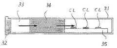
本願出願人が出願した特願2000−044384号「バイオチップ」には、この点が解決され、安全性が高く検査コストの低減が可能なバイオチップが記載されている。このバイオチップは図8に示すような構造である。採血管31は従来のスピッツ管の代わりに注射器に挿入されて採血を行なうもので、励起光や蛍光に対して透明な固形材料で円筒状に形成されている。この採血管31の開口部はその中央部に針が穿刺されるゴム栓32で封止され、採血管31全体は負圧になっている。
【0007】
針を介して採取された血液は、一旦採取部33に保持された後、前処理部34に導かれて前処理が施される。前処理は、例えば血液からリンパ球を分離し、分離されたリンパ球からDNAを抽出し、抽出したDNAに蛍光標識を付加する等の一連の処理である。
【0008】
採血管31の一番奥には、図5に示すのと同様な、既知のDNAがアレイ状に配置された基板35が収納されており、前処理部34から浸透して来るDNAと前記既知のDNAとのハイブリダイズが行われる。
【0009】
【発明が解決しようとする課題】
しかしながら、このようなバイオチップは血液採取から前処理、ハイブリダイズ等が一貫して自動的に行われる利点はあるものの、固い採血管が必要で高価であることや、負圧にするための空気吸引ポンプ等が必要で全体として高価になるという問題がある。
【0010】
本発明の目的は、上記の課題を解決するもので、誤操作により溶液に接触する危険性が未然に防止でき、また操作が簡単でしかも安価な構成のバイオチップを提供することにある。
【0011】
【課題を解決するための手段】
このような目的を達成するために、本発明では、可撓性の材料を用いて偏平な袋状に形成された採血バッグの一端から順に、開口部を密封するように取り付けられ注射針が穿刺されるゴム状の栓と、この栓に穿刺された注射針を介して採取された血液を保持する採取部と、この血液から未知の試料を抽出する前処理部と、予め用意された複数の既知の試料に前記前処理部で抽出した試料を結合させる結合部が配置されてなる一体型の構造としたことを特徴とする。
【0012】
このような構成によれば、採血バッグは安価な材料で作製できるため従来よりも安価になり、また従来は血液を吸い込むためにポンプ等を必要としたが本発明ではそれを必要としないので、全体として安価なバイオチップを実現することができる。
【0013】
この場合、採血バッグは、少なくとも基板が配置される部分を励起光や蛍光に対して透明な材料で形成し、ハイブリダイズした未知の試料が蛍光観察できるようにする。
【0014】
また、採血バッグは、採取部から前処理部に向かって採血バッグを押しつぶして行くことにより、採取部に採取された血液が前処理部に送り込まれ、さらに前処理が施された血液が前記基板に送り込まれるように形成する。
【0015】
前処理部では、採取部の血液からDNAまたはRNAまたは蛋白を試料として抽出する。また、前処理部には、その脇にこの前処理部とつながる袋部が形成され、この袋部には前処理用の溶液が充填されると共に前処理部とつながる接合部には弁が形成され、袋部を押しつぶして溶液に圧力をかけると前記弁が開き袋部の溶液が前処理部に送り込まれるようにする。これにより、簡単な操作で溶液を前処理部に注入することができる。
【0016】
この場合、溶液の入った袋を、複数個配置し、しかもその配置位置を異ならせておき、採血バッグを押しつぶして行くとき各袋部からの溶液が時間差をもって前処理部に流入するように形成することもできる。これにより、前処理部での時間差処理が簡単に実現できる。
【0017】
また、採血バックは、バッグ全幅にわたって同時に押しつぶして行くかまたは複数箇所を個別に押しつぶして行くかして血液あるいは溶液を送ることができるように形成する。このような構成によれば、血液や溶液の送出時点を適宜に変えることができる。
【0018】
採血バッグは、その奥に袋部を形成しそこに廃液を溜めておくことができる。これにより、廃液が外部に漏れ出ることもなく、溶液に接触してHIV等に感染するという危険性もない。
【0019】
また、採取部には、採血時に採取部の膜を外側に引っ張って膨らませるための手段を備えておく。この手段を使って採取部を負圧にすることにより採血が可能となる。
【0020】
【発明の実施の形態】
以下図面を用いて本発明を詳しく説明する。図1は本発明に係るバイオチップの一実施例を示す構成図である。同図(a)は側面図(断面図)、同図(b)は平面図である。図8に示す採血管31が固い材料で円筒状に形成されたものであるのに対し、本発明のバイオチップ40は可撓性に富み励起光や蛍光に対して透明な材料により偏平な密封状のバッグ型に形成されたものである。
【0021】
この採血バッグ41は、図1(b)の平面図に示すように、外形が四角状であって、その周辺部は密封状に接合され、中央部は魚形状の袋になっている。魚の口に相当するバッグの開口部は栓42で密封されている。この栓42はゴム状の材質で形成されており、採血時には注射針がここに刺し通される。採血後注射針を抜くとその針孔は直ちに塞がり、採取した血液が外部へ漏れることはない。
【0022】
採血バッグ41はこの栓42から奥に向かって順に、採取部43、前処理部44、結合部45、廃液収容部47が形成されている。
採取部43には採血した血液が保存される。採取部43の膜の表面と裏面にはそれぞれフック431が形成されており、採血時にはこのフック431に掛合した掛合部材を外側に引っ張って採取部43を膨らませるようにする。
【0023】
前処理部44では、採取した血液から対象の未知の試料を抽出する処理を行なう。結合部45は、既知の試料(ここではDNAとする)を複数個アレイ状に配置した基板46を備え、前処理部44で抽出した試料をこの既知の試料に相補的に結合させることができるようになっている。
廃液収容部47は、前処理部44および結合部45から押し出された不要な溶液を溜めるために設けられた袋部分であり、その袋は初期状態では圧縮されている。
【0024】
前処理部44の両脇には背びれと腹びれに相当するような袋部48と50が魚の背びれと腹びれとはそれぞれ逆向きの関係で形成されている。この袋部48,50には、血液から未知の試料(DNA、RNAあるいは蛋白等)を抽出するために必要な溶液がそれぞれ封入されている。
袋部48,50と前処理部44との接続部分(細い通路)には隔壁用の弁49,51が形成されていて、袋部の溶液の圧力が高くなると破れるように形成されている。
【0025】
このように形成された採血バッグ41の使用方法および動作を図2を参照して説明する。図2は注射器100と採血バッグ41の結合部分の構成図である。
【0026】
注射器100は、注射針101とキャップ102と掛合部材103から構成されている。注射針101はキャップ102を貫通するように取付けられており、キャップ102の開口側に突出した注射針101の長さは、採血バッグ41をキャップ102の開口側から挿入したときに採血バッグ41の栓42を貫通できる程度の長さになっている。
【0027】
掛合部材103は採血バッグ41の採取部43を拡張させるためのもので、可撓性の材料で形成されている。掛合部材103の一端はキャップ102に固着されており、また他端部には採血バッグ41の採取部43のフック431に掛合する掛合部(図示せず)が形成されている。掛合部は周知の手段が適用できる。
なお、注射器100に採血バッグ41を装着すると自動的に掛合部材がフック431に掛合するようになっている。
【0028】
このような注射器100の針101を被験者の腕に刺し、採取部43内が負圧になるように掛合部材103を徐々に開いて血液を採取部43内に採取する。採血後は採血バッグ41を注射器100から取り外し、その後注射器100を被験者の腕から抜去する。
【0029】
このようにして採血した後は、採血バッグ41を図3に示すように回転するローラ61,62に挟んで採取部43から前処理部44の方へ押しつぶして行く。
ローラ61,62は、その軸方向の長さが採血バッグ41の幅よりも長くなっていて、採血バッグ41の全幅を一様に圧接する。
なお、ローラ61,62の駆動機構については周知のものであると共に説明を簡潔にするために、ここでは図示を省略してある。
【0030】
ローラ61,62の回転により採取血液は前処理部44へ押しやられる。ローラ61,62の位置が進み、袋部48を押しつぶし始めると、袋部48内の圧力が上昇して弁49が破れる。弁49が破れると、袋部48内の溶液が前処理部44に流れ込んでその溶液による所定の処理が行なわれる。
続いて、袋部50もローラ61,62により押しつぶされると、同様に弁51が破れて袋部50内の溶液が前処理部44内に流れ込んで所定の処理が行なわれる。
【0031】
したがって、袋部の取付け位置をずらせておくことにより容易に時間差処理を行なわせることができる。すなわち、血液からリンパ球を分離し、分離したリンパ球からDNAを抽出する処理と、抽出したDNAに蛍光標識を付加する処理等を時間的にずらせて行なわせることができる。
【0032】
前処理部44での処理が終了すれば、続いてローラ61,62を回転させる。これにより、処理された血液が結合部45へ送られ、基板46に配置された既知のDNAチップとのハイブリダイズが行われる。
なお、前処理部44から押し出された余分な血液や溶液は廃液収容部47に溜まる。
ハイブリダイズの行われたDNAチップは従来と同様にバイオチップ読み出し装置(図示せず)により読み出される。
【0033】
このように、血液採取から、前処理、ハイブリダイズまでの処理が一貫して密閉の採血バッグ内で行われ、誤操作により溶液に接触するような事故も未然に防ぐことができる。また、このような採血バックは柔軟な可撓性の安価な材料で容易に作製されるので、安価なバイオチップを容易に実現することもできる。
【0034】
なお、本発明は、上記実施例に限定されることなく、その本質から逸脱しない範囲で更に多くの変更、変形をも含むものである。
【0035】
例えば、ローラは上記実施例の形に限定されるものではなく、図4に示すように中央部と、背びれ、腹びれ相当部分用の3つのローラ71,72,73に分離し、しかも各位置を適宜ずらせて配置しても構わない。このような分離・配置とすると、より複雑な時間差処理も容易に可能となる。
【0036】
また、実施例では試料としてDNAを例にとり、前処理部でDNAを抽出する場合を説明したが、試料としてはDNAに限らず、RNAや蛋白等であっても構わない。
【0037】
また、採取部43の膜と注射器100の掛合部材103との掛合方式は、上記実施例に限定されず、例えば接着剤により採取部43の膜と掛合部材103を接着する方式等を適用することもできる。
【0038】
【発明の効果】
以上説明したように本発明によれば次のような効果がある。
(1)密封状の採血バック内で、採取部への血液保存、血液の前処理、ハイブリダイズ処理を一貫して行なうことができ、処理中に血液が外部に漏れ、血液に接触する危険性も未然に防止できる。
【0039】
(2)採血バッグは安価な材料を使用できるため、従来のものより安価なバイオチップを容易に作製できる。
(3)ローラ等により採血バッグを端から押しつぶして行くだけで、試料を前処理部やハイブリダイズ処理部へ簡単に送り込むことができ、従来のように試料を移行させるために空気吸引のポンプ等の複雑な機構は必要としない。
【図面の簡単な説明】
【図1】本発明に係るバイオチップの一実施例を示す構成図である。
【図2】注射器と採血バッグの結合部の構成図である。
【図3】バイオチップの操作方法を示す説明図である。
【図4】本発明の他の実施例図である。
【図5】従来のバイオチップの一例を示す構成図である。
【図6】図5のバイオチップの平面図である。
【図7】従来のバイオチップへの溶液の注入法を示す説明図である。
【図8】従来の他のバイオチップの一例を示す構成図である。
【符号の説明】
40 バイオチップ
41 採血バッグ
42 栓
43 採取部
44 前処理部
45 結合部
46 基板
47 廃液収容部
48,50 袋部
49,51 弁
61,62,71,72,73 ローラ[0001]
BACKGROUND OF THE INVENTION
The present invention relates to a biochip for testing DNA, RNA, protein, and the like, and particularly to a biochip that is highly safe and can reduce testing costs.
[0002]
[Prior art]
A method for testing DNA or the like using a biochip has been well known. FIG. 5 shows an example of a conventional apparatus that reads an array of unknown DNA by scanning a hybridized DNA chip with a biochip reader.
[0003]
In this apparatus, the
[0004]
In this case, the biochip 10 is obtained by storing a
[0005]
However, blood or the like, which is a sample to be examined, may be contaminated with a virus such as HIV, and a disposable instrument is used for a medical instrument such as a syringe for safety. On the other hand, in the solution introduction method as shown in FIG. 7, since the solution is transferred from the solution introduction means 14 to the
In addition, there are problems that the medical instruments to be discarded due to the disposable increase in the number of syringes, instruments used for pretreatment, solution introduction means, DNA chips, etc., and the inspection cost increases.
[0006]
Japanese Patent Application No. 2000-0434384 “Biochip ” filed by the applicant of the present application describes a biochip that solves this problem and that has high safety and can reduce inspection costs. This biochip has a structure as shown in FIG. The
[0007]
The blood collected through the needle is once held in the
[0008]
A
[0009]
[Problems to be solved by the invention]
However, although such a biochip has an advantage that blood collection, pretreatment, hybridization, etc. are performed automatically and consistently, a solid blood collection tube is necessary and expensive, and air for making negative pressure There is a problem in that a suction pump or the like is required and the whole is expensive.
[0010]
An object of the present invention is to solve the above-described problems, and to provide a biochip having a structure that can prevent a risk of contact with a solution due to an erroneous operation, is simple in operation, and is inexpensive.
[0011]
[Means for Solving the Problems]
In order to achieve such an object, according to thepresent invention, a syringe is attached to seal the opening sequentially from one end of a blood collection bag formed into a flat bag shape using a flexible material. A rubber-like stopper, a collecting part for holding blood collected through an injection needle pierced into the stopper, a pretreatment part for extracting an unknown sample from the blood, and a plurality of pre-prepared parts The present invention is characterized in that an integrated structure is formed in which a coupling portion for coupling the sample extracted in the pretreatment unit to a known sample is arranged.
[0012]
According to such a configuration, since the blood collection bag can be made of an inexpensive material, it is cheaper than before, and conventionally, a pump or the like is required to suck in blood, but the present invention does not require it. As a whole, an inexpensive biochip can be realized.
[0013]
In this case, in the blood collection bag, at least a portion where the substrate is arranged is formed of a material transparent to excitation light and fluorescence so that an unknown hybridized sample can be observed with fluorescence.
[0014]
In addition, the blood collection bag crushes the blood collection bag fromthe collection unit toward the pretreatment unit, so that the blood collected in the collection unit is sent to the pretreatment unit, and the pretreated blood is further supplied to the substrate. To be sent to
[0015]
In the pretreatment unit, DNA, RNA, or protein is extracted as a sample from the blood ofthe collection unit. In addition, the pre-processingunit, the bag portion to connect with the pre-processing unit is formed on the side, the valve at the junction to connect with the pre-processing unit with a solution of pretreatment in the bag portion is filled form When the bag portion is crushed and pressure is applied to the solution, the valve is opened so that the solution in the bag portion is sent to the pretreatment portion. Thereby, a solution can be inject | poured into a pre-processing part by simple operation.
[0016]
In this case,a plurality of bags containing the solution are arranged, and the arrangement positions thereof are made different so that when the blood collection bag is crushed, the solution from each bag part flows into the pretreatment part with a time difference. You can also Thereby, the time difference process in a pre-processing part is easily realizable.
[0017]
In addition, the blood collection bag is formed so that blood or a solution can be sent by crushing simultaneously over the entire width ofthe bag or by crushing a plurality of locations individually. According to such a configuration, it is possible to appropriately change the time of blood or solution delivery.
[0018]
Blood collectionbag, may have been accumulated waste therein to form the bag part in its rear. Thereby, the waste liquid does not leak to the outside, and there is no danger of being infected with HIV or the like by contacting the solution.
[0019]
Further, the samplingpart, previously provided with means for inflating the membrane of the collecting portion during blood sampling by pulling outward. Blood can be collected by using this means and setting the collection part to a negative pressure.
[0020]
DETAILED DESCRIPTION OF THE INVENTION
Hereinafter, the present invention will be described in detail with reference to the drawings. FIG. 1 is a block diagram showing an embodiment of a biochip according to the present invention. FIG. 4A is a side view (sectional view), and FIG. 4B is a plan view. Whereas the
[0021]
As shown in the plan view of FIG. 1 (b), the
[0022]
In the
The collected blood is stored in the
[0023]
The preprocessing
The waste
[0024]
On both sides of the
Valves 49 and 51 for partition walls are formed at connecting portions (narrow passages) between the
[0025]
The usage method and operation | movement of the
[0026]
The syringe 100 includes an
[0027]
The engaging
When the
[0028]
The
[0029]
After blood collection in this way, the
The rollers 61 and 62 have a length in the axial direction longer than the width of the
Note that the driving mechanisms of the rollers 61 and 62 are well known and are not shown here for the sake of brevity.
[0030]
The collected blood is pushed to the
Subsequently, when the
[0031]
Therefore, the time difference process can be easily performed by shifting the attachment position of the bag portion. That is, a process of separating lymphocytes from blood and extracting DNA from the separated lymphocytes, a process of adding a fluorescent label to the extracted DNA, and the like can be performed while being shifted in time.
[0032]
When the processing in the
Note that excess blood or solution pushed out from the
The hybridized DNA chip is read out by a biochip reading device (not shown) as in the prior art.
[0033]
In this manner, the processes from blood collection to pretreatment and hybridization are performed consistently in a sealed blood collection bag, and accidents such as accidental contact with the solution can be prevented. In addition, since such a blood collection bag is easily made of a soft, flexible and inexpensive material, an inexpensive biochip can be easily realized.
[0034]
The present invention is not limited to the above-described embodiments, and includes many changes and modifications without departing from the essence thereof.
[0035]
For example, the roller is not limited to the shape of the above embodiment, and as shown in FIG. 4, the roller is separated into a central portion and three
[0036]
In the embodiments, DNA is used as an example, and the case where DNA is extracted by the pretreatment unit has been described. However, the sample is not limited to DNA, and may be RNA, protein, or the like.
[0037]
In addition, the engagement method between the membrane of the
[0038]
【The invention's effect】
As described above, the present invention has the following effects.
(1) Within the sealed blood collection bag, blood storage in the collection part, blood pretreatment, and hybridization treatment can be performed consistently, and the risk of blood leaking to the outside during contact and contact with blood Can also be prevented.
[0039]
(2) Since a cheap material can be used for the blood collection bag, a biochip cheaper than the conventional one can be easily produced.
(3) By simply crushing the blood collection bag from the end with a roller or the like, the sample can be easily sent to the pretreatment unit or the hybridization treatment unit. No complicated mechanism is required.
[Brief description of the drawings]
FIG. 1 is a block diagram showing an embodiment of a biochip according to the present invention.
FIG. 2 is a configuration diagram of a coupling portion between a syringe and a blood collection bag.
FIG. 3 is an explanatory diagram showing a method of operating a biochip.
FIG. 4 is another embodiment of the present invention.
FIG. 5 is a block diagram showing an example of a conventional biochip.
6 is a plan view of the biochip of FIG.
FIG. 7 is an explanatory view showing a conventional method of injecting a solution into a biochip.
FIG. 8 is a block diagram showing an example of another conventional biochip.
[Explanation of symbols]
40
Claims (9)
Translated fromJapanese開口部を密封するように取り付けられ注射針が穿刺されるゴム状の栓と、
前記注射針を介して採取された血液を保持する採取部と、
この採取部につながり、前記採取部が押しつぶされたとき送り込まれる前記血液から未知の試料を抽出する前処理部と、
この前処理部につながり、前記前処理部から送り込まれる前記未知の試料を予め用意された複数の既知の試料に結合させる結合部とが配置されてなり、
前記前処理部とつながり、前記抽出に必要な溶液が封入され、押しつぶされたとき前記溶液を前記前処理部に送り込む袋部が前記前処理部の脇に形成され、
前記採取部に続いて前記袋部が前記前処理部に向かって一様に押しつぶされて行くことにより前記血液から前記未知の試料が抽出され前記結合部に送られる
ことを特徴とするバイオチップ。In order from one end of the blood collection bag formed into a flat bag shape using a flexible material,
A rubber plug that is attached to seal the opening and into which the needle is punctured;
A collection unit for holding blood collected through the injection needle;
Connected to this collection unit, a pre-processing unit that extracts an unknown sample from the blood thatis sent when the collection unit is crushed ,
This leads to the preprocessing unit, makessaid a plurality of placement and coupling portion engagedbinding to a knownsample of the unknown samples were prepared in advancefed from the pre-processing unit,
Connected to the pretreatment unit, the solution necessary for the extraction is enclosed, andwhen crushed, a bag portionfor feeding the solution to the pretreatment unit is formed beside the pretreatment unit,
The biochip is characterized in that, following the collection part, the bag part isuniformly crushed toward the pretreatment part,whereby the unknown sample is extracted from the blood and sent to the coupling part .
液を保持する採取部と、
この採取部につながり、前記採取部が押しつぶされたとき送り込まれる前記液から試料を抽出する前処理部と、
この前処理部につながるとともに前記抽出に必要な溶液が封入され、押しつぶされたとき前記溶液を前記前処理部に送り込む袋部と
を備え、
前記採取部に続いて前記袋部が前記前処理部に向かって一様に押しつぶされて行くことにより前記液から前記試料を抽出する
ことを特徴とするバイオチップ。In a bag formed into a flat bag shape using a flexible material,
A collecting part for holding the liquid;
Connected to this collection unit, a pretreatment unit for extracting a sample from the liquidsent when the collection unit is crushed ,
The solution requiredRutotomoni the extraction connected to the pre-processing unit isenclosed, and a bag portionfor feeding to the pre-processing unit the solution when crushed,
The biochip,wherein the sample is extracted from the liquid by thebag portionbeing uniformly crushed toward the pretreatment portionfollowing the collection portion.
前記採取部に続いて前記袋部が前記前処理部に向かって一様に押しつぶされて行くことにより、前記前処理部で前処理が施された液が前記結合部に送られる
ことを特徴とする請求項2に記載のバイオチップ。In the bag, provided with acoupling unit that connects to the pretreatment unit, and couples the samplefed from the pretreatment unit to a known sample prepared in advance.
Thebag part isuniformly crushed toward the pretreatment partfollowing the sampling part,so that the liquid pretreated in the pretreatment part is sent to the coupling part. The biochip according to claim 2.
前記バッグの少なくとも前記基板が配置される部分は、励起光や蛍光に対して透明な材料で形成された
ことを特徴とする請求項1または3記載のバイオチップ。The coupling portion includes a substrate on which the known samples are arranged in an array,
The biochip according to claim 1 or 3, wherein at least a portion of the bag on which the substrate is disposed is formed of a material transparent to excitation light and fluorescence.
ことを特徴とする請求項1乃至7のいずれかに記載のバイオチップ。The biochip according to any one of claims 1 to 7, wherein a waste liquid storage section for storing excess liquid, blood and solution pushed out from the pretreatment section is formed in the back of the bag.
ことを特徴とする請求項1に記載のバイオチップ。The biochip according to claim 1, wherein the blood collection bag includes an engaging member that expands the collection unit during blood collection.
Priority Applications (2)
| Application Number | Priority Date | Filing Date | Title |
|---|---|---|---|
| JP2001176712AJP4244534B2 (en) | 2001-06-12 | 2001-06-12 | Biochip |
| US10/237,682US7622082B2 (en) | 2001-06-12 | 2002-09-10 | Biochip |
Applications Claiming Priority (2)
| Application Number | Priority Date | Filing Date | Title |
|---|---|---|---|
| JP2001176712AJP4244534B2 (en) | 2001-06-12 | 2001-06-12 | Biochip |
| US10/237,682US7622082B2 (en) | 2001-06-12 | 2002-09-10 | Biochip |
Publications (2)
| Publication Number | Publication Date |
|---|---|
| JP2002365299A JP2002365299A (en) | 2002-12-18 |
| JP4244534B2true JP4244534B2 (en) | 2009-03-25 |
Family
ID=32715479
Family Applications (1)
| Application Number | Title | Priority Date | Filing Date |
|---|---|---|---|
| JP2001176712AExpired - LifetimeJP4244534B2 (en) | 2001-06-12 | 2001-06-12 | Biochip |
Country Status (2)
| Country | Link |
|---|---|
| US (1) | US7622082B2 (en) |
| JP (1) | JP4244534B2 (en) |
Families Citing this family (59)
| Publication number | Priority date | Publication date | Assignee | Title |
|---|---|---|---|---|
| JP3865134B2 (en)* | 2003-01-09 | 2007-01-10 | 横河電機株式会社 | Biochip cartridge |
| US7854897B2 (en) | 2003-05-12 | 2010-12-21 | Yokogawa Electric Corporation | Chemical reaction cartridge, its fabrication method, and a chemical reaction cartridge drive system |
| US20040265171A1 (en)* | 2003-06-27 | 2004-12-30 | Pugia Michael J. | Method for uniform application of fluid into a reactive reagent area |
| US8961900B2 (en)* | 2004-04-28 | 2015-02-24 | Yokogawa Electric Corporation | Chemical reaction cartridge, method of producing chemical reaction cartridge, and mechanism for driving chemical reaction cartridge |
| DE102004022263A1 (en)* | 2004-05-06 | 2005-12-15 | Clondiag Chip Technologies Gmbh | Apparatus and method for detecting molecular interactions |
| US8183052B2 (en)* | 2004-08-19 | 2012-05-22 | Blood Cell Storage, Inc. | Methods and apparatus for sterility testing |
| KR20070085230A (en) | 2004-08-19 | 2007-08-27 | 블러드 셀 스토리지 인코퍼레이티드 | Fluorescent рH detector system and related methods |
| US8497134B2 (en) | 2004-08-19 | 2013-07-30 | Blood Cell Storage, Inc. | Fluorescent detector systems for the detection of chemical perturbations in sterile storage devices |
| CN100484632C (en)* | 2004-11-10 | 2009-05-06 | 横河电机株式会社 | Chemical reaction cartridge, method of manufacturing the same, and chemical reaction cartridge driving system |
| JP4631030B2 (en)* | 2005-06-27 | 2011-02-16 | 独立行政法人産業技術総合研究所 | Needle integrated biosensor |
| JP4692200B2 (en)* | 2005-10-06 | 2011-06-01 | 横河電機株式会社 | Chemical treatment cartridge and method of use thereof |
| US10753927B2 (en) | 2006-09-22 | 2020-08-25 | ALERE TECHNOLOGIES GmbH | Methods for detecting an analyte |
| EP2543440B1 (en)* | 2007-05-03 | 2020-03-25 | Alere Technologies GmbH | Machine for operating a cartridge and particle detection method |
| JP5055617B2 (en)* | 2007-05-25 | 2012-10-24 | 地方独立行政法人 東京都立産業技術研究センター | Dispensing device |
| JP4522434B2 (en)* | 2007-05-31 | 2010-08-11 | キヤノン株式会社 | Blood collection container |
| US8202722B2 (en) | 2007-09-21 | 2012-06-19 | Nec Corporation | Temperature control method and system |
| DE102008054313B4 (en) | 2008-11-03 | 2012-12-13 | Zenteris Gmbh | Cartridge and apparatus for assaying biological samples with temperature-controlled biological responses |
| JP5729530B2 (en)* | 2008-11-14 | 2015-06-03 | 横河電機株式会社 | Capsule and chemical treatment cartridge |
| US8449842B2 (en)* | 2009-03-19 | 2013-05-28 | Thermo Scientific Portable Analytical Instruments Inc. | Molecular reader |
| US8835358B2 (en) | 2009-12-15 | 2014-09-16 | Cellular Research, Inc. | Digital counting of individual molecules by stochastic attachment of diverse labels |
| US9625357B2 (en) | 2011-03-09 | 2017-04-18 | Pixcell Medical Technologies Ltd. | Disposable cartridge for preparing a sample fluid containing cells for analysis |
| US9040307B2 (en) | 2011-05-27 | 2015-05-26 | Blood Cell Storage, Inc. | Fluorescent pH detector system and related methods |
| CN104364392B (en) | 2012-02-27 | 2018-05-25 | 赛卢拉研究公司 | For the composition and kit of numerator counts |
| CN105992648B (en)* | 2013-05-31 | 2019-04-26 | 彼克斯赛尔医疗科技有限公司 | It is used to prepare the box of the sample fluid containing the cell for analysis |
| GB2525104B (en) | 2013-08-28 | 2016-09-28 | Cellular Res Inc | Massively Parallel Single Cell Nucleic Acid Analysis |
| EP3766988B1 (en) | 2015-02-19 | 2024-02-14 | Becton, Dickinson and Company | High-throughput single-cell analysis combining proteomic and genomic information |
| EP3262192B1 (en) | 2015-02-27 | 2020-09-16 | Becton, Dickinson and Company | Spatially addressable molecular barcoding |
| JP7508191B2 (en) | 2015-03-30 | 2024-07-01 | ベクトン・ディキンソン・アンド・カンパニー | Methods and compositions for combinatorial barcoding |
| CN107580632B (en) | 2015-04-23 | 2021-12-28 | 贝克顿迪金森公司 | Methods and compositions for whole transcriptome amplification |
| US11124823B2 (en) | 2015-06-01 | 2021-09-21 | Becton, Dickinson And Company | Methods for RNA quantification |
| KR102395450B1 (en) | 2015-09-11 | 2022-05-09 | 셀룰러 리서치, 인크. | Methods and Compositions for Normalizing Nucleic Acid Libraries |
| US10301677B2 (en) | 2016-05-25 | 2019-05-28 | Cellular Research, Inc. | Normalization of nucleic acid libraries |
| US10640763B2 (en) | 2016-05-31 | 2020-05-05 | Cellular Research, Inc. | Molecular indexing of internal sequences |
| US10202641B2 (en) | 2016-05-31 | 2019-02-12 | Cellular Research, Inc. | Error correction in amplification of samples |
| AU2017331459B2 (en) | 2016-09-26 | 2023-04-13 | Becton, Dickinson And Company | Measurement of protein expression using reagents with barcoded oligonucleotide sequences |
| WO2018132610A1 (en) | 2017-01-13 | 2018-07-19 | Cellular Research, Inc. | Hydrophilic coating of fluidic channels |
| CN110382708A (en) | 2017-02-01 | 2019-10-25 | 赛卢拉研究公司 | Selective amplification using blocking oligonucleotides |
| US10676779B2 (en) | 2017-06-05 | 2020-06-09 | Becton, Dickinson And Company | Sample indexing for single cells |
| US11946095B2 (en) | 2017-12-19 | 2024-04-02 | Becton, Dickinson And Company | Particles associated with oligonucleotides |
| JP2019174251A (en)* | 2018-03-28 | 2019-10-10 | テルモ株式会社 | Inspection tool |
| EP4234717A3 (en) | 2018-05-03 | 2023-11-01 | Becton, Dickinson and Company | High throughput multiomics sample analysis |
| ES3014208T3 (en) | 2018-05-03 | 2025-04-21 | Becton Dickinson Co | Molecular barcoding on opposite transcript ends |
| ES2992135T3 (en) | 2018-10-01 | 2024-12-09 | Becton Dickinson Co | Determine 5 transcription sequences |
| JP7618548B2 (en) | 2018-11-08 | 2025-01-21 | ベクトン・ディキンソン・アンド・カンパニー | Whole-transcriptome analysis of single cells using random priming |
| EP3894552A1 (en) | 2018-12-13 | 2021-10-20 | Becton, Dickinson and Company | Selective extension in single cell whole transcriptome analysis |
| US11371076B2 (en) | 2019-01-16 | 2022-06-28 | Becton, Dickinson And Company | Polymerase chain reaction normalization through primer titration |
| WO2020154247A1 (en) | 2019-01-23 | 2020-07-30 | Cellular Research, Inc. | Oligonucleotides associated with antibodies |
| CN113454234B (en) | 2019-02-14 | 2025-03-18 | 贝克顿迪金森公司 | Heterozygote targeted and whole transcriptome amplification |
| WO2021016239A1 (en) | 2019-07-22 | 2021-01-28 | Becton, Dickinson And Company | Single cell chromatin immunoprecipitation sequencing assay |
| CN114729350A (en) | 2019-11-08 | 2022-07-08 | 贝克顿迪金森公司 | Obtaining full-length V (D) J information for immunohistorian sequencing using random priming |
| US11649497B2 (en) | 2020-01-13 | 2023-05-16 | Becton, Dickinson And Company | Methods and compositions for quantitation of proteins and RNA |
| EP4097228B1 (en) | 2020-01-29 | 2024-08-14 | Becton, Dickinson and Company | Barcoded wells for spatial mapping of single cells through sequencing |
| US12153043B2 (en) | 2020-02-25 | 2024-11-26 | Becton, Dickinson And Company | Bi-specific probes to enable the use of single-cell samples as single color compensation control |
| WO2021231779A1 (en) | 2020-05-14 | 2021-11-18 | Becton, Dickinson And Company | Primers for immune repertoire profiling |
| ES2987035T3 (en) | 2020-06-02 | 2024-11-13 | Becton Dickinson Co | Oligonucleotides and beads for gene expression assay 5 |
| US11932901B2 (en) | 2020-07-13 | 2024-03-19 | Becton, Dickinson And Company | Target enrichment using nucleic acid probes for scRNAseq |
| US12391940B2 (en) | 2020-07-31 | 2025-08-19 | Becton, Dickinson And Company | Single cell assay for transposase-accessible chromatin |
| WO2022109343A1 (en) | 2020-11-20 | 2022-05-27 | Becton, Dickinson And Company | Profiling of highly expressed and lowly expressed proteins |
| US12392771B2 (en) | 2020-12-15 | 2025-08-19 | Becton, Dickinson And Company | Single cell secretome analysis |
Family Cites Families (11)
| Publication number | Priority date | Publication date | Assignee | Title |
|---|---|---|---|---|
| EP0139373A1 (en) | 1983-08-26 | 1985-05-02 | The Regents Of The University Of California | Multiple immunoassay system |
| US5223219A (en) | 1992-04-10 | 1993-06-29 | Biotrack, Inc. | Analytical cartridge and system for detecting analytes in liquid samples |
| US5405510A (en)* | 1992-05-18 | 1995-04-11 | Ppg Industries, Inc. | Portable analyte measuring system for multiple fluid samples |
| US5290518A (en)* | 1992-08-17 | 1994-03-01 | Eastman Kodak Company | Flexible extraction device with burstable sidewall |
| US5422271A (en)* | 1992-11-20 | 1995-06-06 | Eastman Kodak Company | Nucleic acid material amplification and detection without washing |
| JP3594979B2 (en) | 1992-10-23 | 2004-12-02 | イーストマン コダック カンパニー | Storage device for increasing and detecting nucleic acid material |
| CA2156226C (en) | 1994-08-25 | 1999-02-23 | Takayuki Taguchi | Biological fluid analyzing device and method |
| US5747666A (en)* | 1997-03-26 | 1998-05-05 | Willis; John P. | Point-of-care analyzer module |
| JPH11133027A (en) | 1997-10-30 | 1999-05-21 | Kdk Corp | Instrument for analyzing component in red blood corpuscle |
| JP3757412B2 (en)* | 2000-02-22 | 2006-03-22 | 横河電機株式会社 | Biochip |
| US6686204B2 (en)* | 2001-08-27 | 2004-02-03 | Becton, Dickinson & Company | Collection device |
- 2001
- 2001-06-12JPJP2001176712Apatent/JP4244534B2/ennot_activeExpired - Lifetime
- 2002
- 2002-09-10USUS10/237,682patent/US7622082B2/ennot_activeExpired - Fee Related
Also Published As
| Publication number | Publication date |
|---|---|
| JP2002365299A (en) | 2002-12-18 |
| US20040047769A1 (en) | 2004-03-11 |
| US7622082B2 (en) | 2009-11-24 |
Similar Documents
| Publication | Publication Date | Title |
|---|---|---|
| JP4244534B2 (en) | Biochip | |
| US20040137607A1 (en) | Biochip cartridge | |
| US20010008614A1 (en) | Sample collection system and method of use thereof | |
| US20130209993A1 (en) | Sample collection system and method for use thereof | |
| EP1285695A3 (en) | Packaging system for test sensors | |
| US20110204084A1 (en) | Sample Collection System and Method for Use Thereof | |
| JP3757412B2 (en) | Biochip | |
| JP3865134B2 (en) | Biochip cartridge | |
| CN212391308U (en) | Biological safety type body fluid specimen processing device | |
| JP2516734B2 (en) | Device and method for opening an ampoule | |
| CN107561262A (en) | Integral biological and chemical reaction equipment | |
| JP2006308428A (en) | Nucleic acid analysis method, nucleic acid analyzer, and cartridge for nucleic acid analysis | |
| KR101821020B1 (en) | An integral saliva collecting device | |
| JP2008175608A (en) | Chemical reaction cartridge and method of use thereof | |
| JP4069747B2 (en) | Separable biochip | |
| JP2006329728A5 (en) | ||
| JP2006329728A (en) | Specimen collection liquid container | |
| JP4492396B2 (en) | Sample collection liquid container | |
| JP2010169543A (en) | Blood separation vessel and method of separating blood | |
| JPS59131332A (en) | Apparatus for sampling body fluids | |
| JPH08308819A (en) | Blood-gathering device and its manufacture | |
| JP2009261540A (en) | Medical adapter and chemical reaction cartridge | |
| JPH0954082A (en) | Specimen sampling container | |
| CN111521802A (en) | Special kit for screening gastric precancerous lesions | |
| KR102784971B1 (en) | Tube vessel for self diagostic kit |
Legal Events
| Date | Code | Title | Description |
|---|---|---|---|
| A621 | Written request for application examination | Free format text:JAPANESE INTERMEDIATE CODE: A621 Effective date:20051109 | |
| A521 | Written amendment | Free format text:JAPANESE INTERMEDIATE CODE: A523 Effective date:20051115 | |
| A977 | Report on retrieval | Free format text:JAPANESE INTERMEDIATE CODE: A971007 Effective date:20070803 | |
| A131 | Notification of reasons for refusal | Free format text:JAPANESE INTERMEDIATE CODE: A131 Effective date:20070827 | |
| A521 | Written amendment | Free format text:JAPANESE INTERMEDIATE CODE: A523 Effective date:20071026 | |
| A131 | Notification of reasons for refusal | Free format text:JAPANESE INTERMEDIATE CODE: A131 Effective date:20080522 | |
| A521 | Written amendment | Free format text:JAPANESE INTERMEDIATE CODE: A523 Effective date:20080722 | |
| TRDD | Decision of grant or rejection written | ||
| A01 | Written decision to grant a patent or to grant a registration (utility model) | Free format text:JAPANESE INTERMEDIATE CODE: A01 Effective date:20081216 | |
| A01 | Written decision to grant a patent or to grant a registration (utility model) | Free format text:JAPANESE INTERMEDIATE CODE: A01 | |
| A61 | First payment of annual fees (during grant procedure) | Free format text:JAPANESE INTERMEDIATE CODE: A61 Effective date:20081229 | |
| R150 | Certificate of patent or registration of utility model | Ref document number:4244534 Country of ref document:JP Free format text:JAPANESE INTERMEDIATE CODE: R150 Free format text:JAPANESE INTERMEDIATE CODE: R150 | |
| FPAY | Renewal fee payment (event date is renewal date of database) | Free format text:PAYMENT UNTIL: 20120116 Year of fee payment:3 | |
| FPAY | Renewal fee payment (event date is renewal date of database) | Free format text:PAYMENT UNTIL: 20120116 Year of fee payment:3 | |
| FPAY | Renewal fee payment (event date is renewal date of database) | Free format text:PAYMENT UNTIL: 20130116 Year of fee payment:4 | |
| FPAY | Renewal fee payment (event date is renewal date of database) | Free format text:PAYMENT UNTIL: 20140116 Year of fee payment:5 | |
| EXPY | Cancellation because of completion of term |