JP4243354B2 - Method for determining an arrival angle of a signal transmitted by a remote device in a communication system - Google Patents
Method for determining an arrival angle of a signal transmitted by a remote device in a communication systemDownload PDFInfo
- Publication number
- JP4243354B2 JP4243354B2JP53661998AJP53661998AJP4243354B2JP 4243354 B2JP4243354 B2JP 4243354B2JP 53661998 AJP53661998 AJP 53661998AJP 53661998 AJP53661998 AJP 53661998AJP 4243354 B2JP4243354 B2JP 4243354B2
- Authority
- JP
- Japan
- Prior art keywords
- sector
- energy
- determining
- signal
- prompt ray
- Prior art date
- Legal status (The legal status is an assumption and is not a legal conclusion. Google has not performed a legal analysis and makes no representation as to the accuracy of the status listed.)
- Expired - Lifetime
Links
- 238000004891communicationMethods0.000titleclaimsdescription23
- 238000000034methodMethods0.000titleclaimsdescription22
- 238000012935AveragingMethods0.000claimsdescription5
- 230000003321amplificationEffects0.000claims16
- 238000003199nucleic acid amplification methodMethods0.000claims16
- 238000002592echocardiographyMethods0.000description10
- 230000001413cellular effectEffects0.000description4
- 238000010586diagramMethods0.000description4
- 230000005540biological transmissionEffects0.000description2
- 230000001427coherent effectEffects0.000description2
- 230000007423decreaseEffects0.000description2
- 238000005259measurementMethods0.000description2
- 230000000737periodic effectEffects0.000description2
- 238000001228spectrumMethods0.000description2
- 238000010897surface acoustic wave methodMethods0.000description2
- 230000006978adaptationEffects0.000description1
- 230000002457bidirectional effectEffects0.000description1
- 239000002131composite materialSubstances0.000description1
- 230000007547defectEffects0.000description1
- 230000001934delayEffects0.000description1
- 230000000694effectsEffects0.000description1
- 238000005562fadingMethods0.000description1
- 238000010295mobile communicationMethods0.000description1
- 238000012986modificationMethods0.000description1
- 230000004048modificationEffects0.000description1
- 238000012545processingMethods0.000description1
Images


Classifications
- G—PHYSICS
- G01—MEASURING; TESTING
- G01S—RADIO DIRECTION-FINDING; RADIO NAVIGATION; DETERMINING DISTANCE OR VELOCITY BY USE OF RADIO WAVES; LOCATING OR PRESENCE-DETECTING BY USE OF THE REFLECTION OR RERADIATION OF RADIO WAVES; ANALOGOUS ARRANGEMENTS USING OTHER WAVES
- G01S3/00—Direction-finders for determining the direction from which infrasonic, sonic, ultrasonic, or electromagnetic waves, or particle emission, not having a directional significance, are being received
- G01S3/02—Direction-finders for determining the direction from which infrasonic, sonic, ultrasonic, or electromagnetic waves, or particle emission, not having a directional significance, are being received using radio waves
- G01S3/04—Details
- G01S3/043—Receivers
- G—PHYSICS
- G01—MEASURING; TESTING
- G01S—RADIO DIRECTION-FINDING; RADIO NAVIGATION; DETERMINING DISTANCE OR VELOCITY BY USE OF RADIO WAVES; LOCATING OR PRESENCE-DETECTING BY USE OF THE REFLECTION OR RERADIATION OF RADIO WAVES; ANALOGOUS ARRANGEMENTS USING OTHER WAVES
- G01S3/00—Direction-finders for determining the direction from which infrasonic, sonic, ultrasonic, or electromagnetic waves, or particle emission, not having a directional significance, are being received
- G01S3/02—Direction-finders for determining the direction from which infrasonic, sonic, ultrasonic, or electromagnetic waves, or particle emission, not having a directional significance, are being received using radio waves
- G01S3/14—Systems for determining direction or deviation from predetermined direction
- G01S3/28—Systems for determining direction or deviation from predetermined direction using amplitude comparison of signals derived simultaneously from receiving antennas or antenna systems having differently-oriented directivity characteristics
- G01S3/30—Systems for determining direction or deviation from predetermined direction using amplitude comparison of signals derived simultaneously from receiving antennas or antenna systems having differently-oriented directivity characteristics derived directly from separate directional systems
- G—PHYSICS
- G01—MEASURING; TESTING
- G01S—RADIO DIRECTION-FINDING; RADIO NAVIGATION; DETERMINING DISTANCE OR VELOCITY BY USE OF RADIO WAVES; LOCATING OR PRESENCE-DETECTING BY USE OF THE REFLECTION OR RERADIATION OF RADIO WAVES; ANALOGOUS ARRANGEMENTS USING OTHER WAVES
- G01S5/00—Position-fixing by co-ordinating two or more direction or position line determinations; Position-fixing by co-ordinating two or more distance determinations
- G01S5/02—Position-fixing by co-ordinating two or more direction or position line determinations; Position-fixing by co-ordinating two or more distance determinations using radio waves
- G01S5/04—Position of source determined by a plurality of spaced direction-finders
- G—PHYSICS
- G01—MEASURING; TESTING
- G01S—RADIO DIRECTION-FINDING; RADIO NAVIGATION; DETERMINING DISTANCE OR VELOCITY BY USE OF RADIO WAVES; LOCATING OR PRESENCE-DETECTING BY USE OF THE REFLECTION OR RERADIATION OF RADIO WAVES; ANALOGOUS ARRANGEMENTS USING OTHER WAVES
- G01S1/00—Beacons or beacon systems transmitting signals having a characteristic or characteristics capable of being detected by non-directional receivers and defining directions, positions, or position lines fixed relatively to the beacon transmitters; Receivers co-operating therewith
- G01S1/02—Beacons or beacon systems transmitting signals having a characteristic or characteristics capable of being detected by non-directional receivers and defining directions, positions, or position lines fixed relatively to the beacon transmitters; Receivers co-operating therewith using radio waves
- G01S1/04—Details
- G01S1/045—Receivers
Landscapes
- Physics & Mathematics (AREA)
- Engineering & Computer Science (AREA)
- General Physics & Mathematics (AREA)
- Radar, Positioning & Navigation (AREA)
- Remote Sensing (AREA)
- Mobile Radio Communication Systems (AREA)
- Radio Transmission System (AREA)
- Position Fixing By Use Of Radio Waves (AREA)
Description
Translated fromJapanese発明の分野
本発明は、一般的に、ワイヤレス通信システムに関し、特に、ワイヤレス通信システムにおいて遠隔装置が送信した信号の到達角度を判定する方法および装置に関するものである。
発明の背景
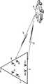
ワイヤレス通信システム内における遠隔装置の位置は、振幅差に基づく到達角度推定(AD−AOA:Amplitude Difference-based Angle Of Arrival estimation)を用いて判定可能であることは既知である。かかるAD−AOA位置判定方法は、Imazekiによる米国特許番号第4,636,796号,RADIO DIRECTION FINDING SYSTEM,およびNossenによる米国特許番号第4,833,478号,AUTOMATIC DIRECTION FINDER ANTENNA ARRAYに記載されている。双方の特許は、本願においても使用可能である。かかる方法によれば、基地サイトにおける多数のアンテナ間の振幅差を分析することによって、遠隔装置から送信された信号の到達角度を判定する。かかる方法を第1図および第2図に示す。第1図に示すように、セクタ化された基地サイト101は、複数の受信アンテナ103〜113を備えており、遠隔装置117から送信された信号115を受信する。明白であるが、セクタα内のアンテナ103,105は、セクタβ内のアンテナ107,109とは異なる到達角度で信号117を受信する。このために、セクタα内のアンテナは、受信する信号の117の振幅も、セクタβ内のアンテナとは異なる。信号117の到達角度を判定する際に利用するのは、種々のアンテナにおける信号117の受信振幅の差である。
第2図は、信号117の減衰を、到達角度の関数として示す。図示のように、ボアサイト(即ち、最大利得の方向)では、セクタα内の105°のセル・サイト・アンテナは、約11dBの利得を有する。ボアサイトから20°では、利得は多少減少するのみであるが、セクタβ内のアンテナにとっては、この到達角度はそれらのボアサイトから100°の方向であり、その利得はわずか1dBであり、結果的に10dBもの信号差が生ずる。この差は、信号117の到達角度がセクタαからセクタβに向かってシフトするに連れて減少する。AD−AOA判定において利用されるのは、この各セクタ・アンテナにおける信号振幅間の関係である。測定した振幅差を到達角度に等しくするには、テーブルの参照を用いることができる。
陸上移動環境では、遠隔装置からの受信信号は、マルチパス散乱を生ずる。言い換えると、加入者によって送信される信号は、受信機で受信される前に、多数回反射し、これらの反射が送信信号の「エコー」を生じ、受信機によって受信される。これらのエコーは、通常振幅や時間遅延が異なっており、したがって、各加入者から受信される信号は、実際には多数の信号(第1到達,またはプロンプト信号およびそのエコー)で構成され、各信号の振幅,到達角度,および時間遅延は異なる。従来技術のAD−AOA方法は、かかるマルチパス散乱を考慮に入れていないので、到達角度の判定はいずれもマルチパス散乱によって転化する。加えて、従来技術のAD−AOA方法は、全てのアンテナにおいて受信機の利得が等しいことを保証できない。これができないために、判定したいずれの到達角度にも、相当の誤差が加わることになる。
従来技術のAD−AOA方法はマルチパス散乱を考慮することができず、しかも全てのアンテナにおける受信機の利得が等しいことを保証できないので、従来技術のAD−AOA干渉方法は、いずれの到達角度の推定においても欠陥がある。したがって、ワイヤレス通信システムにおいて、受信信号のマルチパス散乱を考慮し、更に受信利得が等しくない場合も考慮し、AD−AOA推定を改善しつつ、遠隔装置の到達角度を判定する方法および装置が必要とされている。
【図面の簡単な説明】
第1図は、ワイヤレス通信システムにおける振幅差に基づく到達角度(AD−AOA)の使用を示す。
第2図は、無線周波数(RF)信号の減衰を、到達角度の関数として示す。
第3図は、本発明の好適実施例による通信システムのブロック図である。
第4図は、マルチパス反射を生じたRF信号の受信を示す。
第5図は、本発明の好適実施例による、第3図の増幅器のブロック図である。
第6図は、本発明の好適実施例による、第3図の基地局の動作を示すフロー・チャートである。
図面の詳細な説明
概して言えば、ワイヤレス通信システム内における遠隔装置の位置は、振幅差に基づく到達角度推定(AD−AOA)を利用することによって判定する。即ち、マルチパス散乱を生じた信号からのプロンプト・レイ(prompt ray)を多数のアンテナによって受信する。各アンテナにおいて受信されたプロンプト・レイを、信号コンバイナ/平均計算部によって結合する。次に、信号コンバイナ/平均計算部は、多数のパワー制御群にわたって合計したプロンプト・レイのエネルギの平均を計算し、合計したプロンプト・レイに対する高精度のエネルギ・レベルを判定する。次に、合計したプロンプト・レイの平均エネルギ値をAOA計算部に、他のセクタにおいて合計したプロンプト・レイの平均エネルギ値と共に出力する。各セクタから受信した合計プロンプト・レイのエネルギ値を分析し、適切な到達角度を判定する。
本発明は、通信システムにおいて遠隔装置の位置を判定する方法も含む。この方法はセクタ化した基地サイト内に存在する第1および第2アンテナにおいてRF信号を受信する段階であって、RF信号が、マルチパス散乱を生ずることによって生成された複数のレイから成る、段階と、第1および第2アンテナにおいて受信した複数のレイから、プロンプト・レイを識別する段階とを含む。RF信号の到達角度は、第1および第2アンテナにおいて受信したプロンプト・レイを分析することによって判定する。本発明の好適実施例では、第1および第2アンテナにおいて識別したプロンプト・レイのエネルギを判定し、次いで第1および第2アンテナにおいて識別したプロンプト・レイのエネルギから到達角度を判定することによって、到達角度を判定する。
更に、本発明は、通信システム内において遠隔装置の位置を判定する方法も含む。この方法は、セクタ化した基地サイトの第1セクタ内に存在する第1アンテナにおいてRF信号を受信する段階を含む。RF信号は、マルチパス散乱を生ずることによって生成された複数のレイから成る。更に、前述のセクタ化した基地サイトの第1セクタ内に存在する第2アンテナにおいても、RF信号を受信する。セクタ内の各アンテナにおいて、プロンプト・レイを識別し、これらのプロンプト・レイを合計して、合計プロンプト・レイを生成する。最後に、合計プロンプト・レイに基づいて、到達角度を判定する。即ち、合計プロンプト・レイの第1エネルギを判定し、第3アンテナにおいて受信したプロンプト・レイを第4アンテナにおいて受信したプロンプト・レイと合計し、第2合計プロンプト・レイを生成することによって、到達角度を判定する。第2合計プロンプト・レイのエネルギを判定し、第1および第2エネルギに基づいて到達角度を判定する。
最後に、本発明は、通信システムにおいて遠隔装置の位置を判定する装置を含む。この装置は、セクタ化した基地サイト内に存在する第1受信機を含む。第1受信機は、無線周波数(RF)信号入力を有し、プロンプト・レイを出力として有する。プロンプト・レイは、マルチパス散乱を生じたRF信号によって生成される。更に、本装置は、セクタ化した基地サイト内に存在する第2受信機も備えている。第2受信機は、第2RF信号入力を有し、プロンプト・レイを出力として有する。最後に、受信機は、第1受信機からのプロンプト・レイおよび第2受信機からのプロンプト・レイを入力として有し、RF信号の到達角度を出力として有する、到達角度計算部を備えている。
第3図は、本発明の好適実施例による通信システム300のブロック図である。本発明の好適実施例においては、通信システム300は、TIA/EIA Interim Standard IS-95A,Mobile Station-Base Station Compatibility Standards for Dual-Mode Wideband Spread Spectrum Cellular Systems,Telecommunications Industry Association,Washington,DC July 1993(IS-95A)に詳細に記載されている、符号分割多元接続(CDMA)システム・プロトコルを利用する。この文書の内容は、本願でも使用可能である。本発明の好適実施例では、通信システム300はCDMAシステム・プロトコルを利用するが、通信システム300は、狭帯域先進移動電話サービス(NAMPS:Narrowband Advanced Mobile Phone Service)プロトコル,先進移動電話サービス(AMPS:Advanced Mobile Phone Service)プロトコル,個人ディジタル・セルラ(PDC:Personal Digital Cellular)プロトコル,移動通信用グローバル・システム(GSM:Global System for Mobile Communications)プロトコル,双方向ページング・プロトコル,または米国ディジタル・セルラ(USDC:United States Digital Cellular)プロトコルのような、他のシステム・プロトコルも使用可能である。尚、他のシステム・プロトコルは、これらに限定される訳ではない。
図示のように、通信システム300は、3つのセクタから成る、セクタ化基地サイト101を備えている。基地サイト101の各セクタは、各受信機303,305に結合された、並列指向アンテナ(parallel pointed antenna)103,105を有する。基地サイト101は3セクタ基地サイトとして示すが、本発明の別の実施例では、基地サイト101は、いずれの数のセクタでも含むことができる。一方、受信機303,305は、信号コンバイナ/平均計算部307および基地サイト回路317に結合されている。図示のように、信号コンバイナ/平均計算部307は、基地サイト・コントローラ(BSC)311への出力を有する、AOA計算部309に結合されている。本発明の好適実施例では、AOA計算部309は基地サイト101内に示されているが、本発明の別の実施例では、AOA計算部は、通信システム300内部のどこに配置してもよい(例えば、BSC311内)。第3図には示さないが、基地サイト101の各セクタ内には、同一のアンテナ103,105,受信機303,305,および信号コンバイナ307が備えられており、各信号コンバイナ/平均計算部307からの出力はAOA計算部309に送られる。
本発明の好適実施例による通信システム300の動作は、次のように行われる。エンコード・スペクトル拡散ディジタル信号117が、アンテナ103,105(および恐らく通信システム300内の他のアンテナ)において受信される。本発明の好適実施例では、信号117は、個々の遠隔装置からの多数の周波数および時間重複コード化信号から成る。これらの信号の各々は、同じ無線周波数(RF)で同時に送信され、その特定の変調および拡散によってのみ区別可能である。言い換えると、基地局受信機において受信されるアップリンク信号は、各送信信号の複合信号であり、各加入者の信号は、逆拡散および復調の後初めて区別可能となる。信号117は、増幅器319,321によって増幅され、その結果増幅信号340,341が得られる。信号340,341は、ディスプレッダ321,327にそれぞれ入力され、ここで逆拡散され、逆拡散信号342,343としてそれぞれ復調器323,329に出力される。信号342,343(単一の遠隔装置からの送信を表す)は、次に、同相(I)成分344および直交(Q)成分345に復調される。先に論じたように、I成分およびQ成分は、受信される前に、多数回反射しており、これらの反射がI成分およびQ成分のエコーを生じ、受信機303,305によって出力される。第4図に示すように、これらのエコーは、通常、振幅および時間遅延が異なり、したがって、各遠隔装置のI成分およびQ成分は、実際には多数の成分(即発成分401およびそのエコー403,405)で構成されており、その各々が異なる振幅,到達角度,および時間遅延を有する。簡略化のために、第3図は、単一のディスプレッダ/復調器の組み合わせから現出した即発成分401およびそのエコー403,405を示すが、本発明の好適実施例では、受信機303,305は、信号117の各成分401,403,405に別個のディスプレッダ/復調器対(321/323,327/329)を割り当てる。
続いて、I成分およびQ成分ならびにそれらのエコー(信号344,345)は、次に受信機303,305によって信号コンバイナ/平均計算部307および基地サイト回路317に同時に出力される。本発明の好適実施例では、基地サイト回路317は、IS−95Aに記載されているように、各遠隔装置のIおよびQ成分の標準的なCDMA結合およびデコードを行うために必要な回路を備えている。例えば、従来技術のコンバイナ331は、各受信機303,305からI成分およびQ成分ならびにそれらのエコーを受信し、エコーを結合して1つのコヒーレント信号を形成する(即ち、6つの成分が受信され(各アンテナから3つずつ)、次いでこれらの成分を1つに結合する)。別の言い方をすれば、特定の遠隔装置の送信(散乱を生じている)を含む信号344,345が、それぞれ、逆拡散信号342,343として、ディスプレッダ321,327から出力される。逆拡散信号342,343は、それぞれ、復調器323,329によって復調され、その結果、遠隔装置から送信された6つ(各アンテナから3つずつ)の逆拡散復調信号が得られる。これらの逆拡散復調信号は各々I成分およびQ成分を含む。従来技術のコンバイナ331は、受信した全ての成分およびエコーを結合し、1つのコヒーレントなIおよびQ信号を形成する。この信号は、所定の長さのサンプル信号群(例えば、64サンプル長の群)に集合化され、直交デコーダ333に独立して入力され、続いてデコードされる。
本発明の好適実施例では、AD−AOA推定を必要とする、遠隔装置に対するI成分およびQ成分ならびにエコーは、信号コンバイナ/平均計算部307に入力され、信号の結合を行い、個々のIおよびQ成分を合計し、その結果合計IおよびQ成分を得る。別の言い方をすれば、アンテナ103から最初に到達した成分(即ち、プロンプト・レイ401)は、エコー403または405とは合計されず、代わりにアンテナ105からのプロンプト・レイ401と合計され、合計プロンプト・レイを形成する。加えて、アンテナ103からのエコー403は、アンテナ105からのエコー403と合計され、アンテナ103からのエコー405は、アンテナ105からのエコー405と合計される。本発明の好適実施例では、この合計の結果、3つのI成分および3つのQ成分が得られる。本発明の好適実施例では、信号コンバイナ/平均計算部307は、多数のパワー制御群にわたって合計したプロンプト・レイのエネルギの平均を取り、プロンプト・レイ401の正確なエネルギ・レベルを判定する。
次に、合計プロンプト・レイの平均エネルギ値は、他のセクタにおける合計プロンプト・レイの平均エネルギ値と共に、AOA計算部309に出力される。各セクタにおいて受信されたプロンプト・レイのエネルギ値を分析し、適切な到達角度を判定する。本発明の好適実施例では、これを行う際に、以下に説明するAD−AOD技法を用いる。一旦AOA計算部309によって信号117の実際の到達角度が判定されたなら、BSC311および測位サービス・センタ(location service center)313に出力する。
本発明の好適実施例の実施によって遭遇し得る1つの問題は、1つのセクタに対する信号振幅が、他の2つのセクタのいずれかよりも大きくなる可能性があることである(これは非常に低いため、エネルギ測定値はノイズによって激しく転化され、使用不可能となる虞れがある)。本発明の好適実施例では、この問題を回避するために、多数の手段を採用する。例えば、本発明の譲受人に譲渡された、米国特許番号第5903844号(弁理士整理番号第CE−03200R号)、Bruckert et al.によるMETHOD AND APPARATUS FOR DETERMINING REMOTE UNIT LOCATION IN COMMUNICATION SYSTEMに記載されているように、間隔に対するパワー制御ビットをハイにセットするか、あるいは遠隔装置に特殊メッセージを送るように要求することによって、信号117を増大することができる。すると、既知の信号を送信することによって、または最強の信号を復調しこれを用いることによって、信号をコヒーレントに復調し、弱い方の信号を復調することが可能となる。
本発明の好適実施例では、増幅器319,325は、本発明の譲受人に譲渡された、Turney et al.による米国特許番号第4,334,185号、A CIRCUIT FOR AUTOMATIC GAIN CONTROL WITH CONSTANT RESPONSE TIMEに記載されているように、自動利得制御(AGC)を利用する。したがって、増幅器319,325から出力される信号340,341の振幅は一定に保持される。AGCによって、アンテナ毎に、またセクタ毎に受信機の利得の不整合が生ずる。例えば、ボアサイト上を1対のダイバシティ・アンテナに着信する信号は、他のセクタのボアサイトに移動させた場合、同じ振幅を有するはずである。AGCのために、このようにならない場合がある。したがって、AGCの影響を解消するために、利得が異なる増幅器に対処する必要がある。本発明の好適実施例では、これは、既知の振幅信号で各受信機を較正することによって行う。即ち、周期的な間隔でアンテナ103,105(および通信システム300内の全アンテナ)のベースにおいて、較正信号を挿入する。通常のAGCは較正信号上で行われ、AGC値(増幅器利得値)が信号コンバイナ/平均計算部307に出力される。これは、第3図において、それぞれ、増幅器319,325からの出力信号346,347として示されている。信号コンバイナ/平均計算部307は、AGC値346,347を利用し、それに応じてI信号344およびQ信号345のスケーリングを行う。
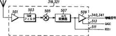
第5図は、本発明の好適実施例による、第3図の増幅器のブロック図である。この増幅器は、第1増幅器501,表面弾性波(SAW:Surface Acoustic Wave)フィルタ503,局部発振器505,アナログ/ディジタル(A/D)変換器507,およびAGC増幅器509を備えている。A/D変換器511の出力に加えて、出力AGC利得値513および増幅器出力340,341がある。AGC増幅器509の出力は、アタック・タイム(attack time)が約100μ秒以内までの一定電圧である。言い換えると、1.25msパワー制御群(PCG)の間隔の平均パワーは、全ての間隔および全てのアンテナ・ブランチに対して一定であり同一である。本発明の好適実施例では、AGCは、集団フェーディング(ensemble fading)や、ボコーダ・レート適応化(忙繁時現象)による集団パルス振幅変調にさえも追従する程に高速である。増幅信号340,341におけるレイ(ray)のエネルギは、単に出力511におけるエネルギにAGC利得(GAGC)を乗算した値となる。本発明の好適実施例では、利得は、ウオルシュ・シンボルの途中では変更しない。何故なら、これを行うと、復調器の出力に影響を及ぼし、トラフィック負荷が非常に多い場合に、誤った結果を与える虞れがあるためである。
フィンガ復調器は、信号コンバイナ/平均計算部307に、選択したレイ・パワーの推定値(Pmcc)を全体(先に示したように一定である)の分数として供給することができる。したがって、AGC増幅器509以前のパワーは、Pmcc/GAGCとなる。アンテナ入力端子からA/D変換器出力までの利得(GB)は、2レベルの較正によって求められる。即ち、最初のレベルは、利得の固定部分を測定する一時効果(one-time effort)であり、第2レベルは、時間変動部分を測定する周期的較正である。位置間隔の期間にわたってブランチ利得変動がほぼ固定される。αおよびβセクタの信号レベルは、次の通りである。
Aα=(Σ(Pmcc,1,α/GAGC,1,α)GB,1,α+Σ(Pmcc,2,α/GAGC,2,α)GB,2,α)/2
Aβ=(Σ(Pmcc,1,β/GAGC,1,β)GB,1,β+Σ(Pmcc,2,β/GAGC,2,β)GB,2,β)/2
ここで、Pmcc,N,x=x番目のセクタにおけるN番目のアンテナからの平均信号パワー,および
GAGC,N,x=x番目のセクタにおけるN番目のアンテナ・ブランチのAGC利得。
所望の統計量は、単にAα/Aβである。典型的に、Pmccは、PCG全体の平均を取ることによって求められる。何故なら、GAGCはPCGからPCGまで変化する可能性があり、Pmcc/GAGC項をPCGに制限しなければならないことを示唆するからである。本発明の別の実施例では、2つの信号ブランチの平均を取る代わりに、2つの内大きい方を選択し、合計に用いる。
次に復調器に移る。1つの信号からのフィンガの出力344,345は、選択した信号振幅の推定値を与える。実際には、フィンガ電圧出力(v)は、信号電圧(群)およびノイズ項(n)の和であり、分散≒(増幅信号−Pmcc)/64である。
v=s(t)+n(t)
信号が既知であると仮定すると、vは、少なくともPCGの期間だけ、二乗計算に先立つ、kサンプルの期間にわたって合計したベクトルとし、推定値を改善することができる。式(線形、dBではない)は次の通りである。
vavg=(Σs+Σn)/6
=s+Σn/6
Pmccについて解くと、
Pmcc=s2=vavg2−Σn2/36−2*s*Σn/6−2*Σ(nini)/36
典型的に、vavg2は、復調器によって出力され、pcb極性を設定するためにどこかで用いられる。双方のDC項に対して十分な平均化を行い、前述の2つのAC項の影響およびGAGCのPCG毎の重み付けによる追加の影響を減少させれば、n2をその期待値で置換する近似
Pmcc=s2≒vavg2−var(n)/6
が成り立つ。その場合でも、信号項がノイズ項に余りに近づき過ぎる場合、以降の処理ステップにおいてその値を使用すべきでない。
nの分散を推定するには2つの方法がある。以下の式を記しておく。
増幅信号=Σ(ウオルシュ0ないし63)2
ここで、ウオルシュN=信号の復調に用いる高速アダマール変換器のN番目の出力ポートの値
var(n)≒(増幅信号−vavg2)/63≒増幅信号/64(sが小さい場合)
または、
var(n)≒(Σウオルシュ(i)2−v2)/63
前者の式における多数のPCGまたは後者の式における多数のウオルシュ・シンボルにわたって平均を取ることによって、優れた推定を行うことができる。最後に、増幅信号が同一で一定である場合、var(n)は分析的に求めることができる。
第6図は、本発明の好適実施例による、第3図の基地局の動作を示すフロー・チャートである。この論理フローはステップ601にて開始し、ここでRF信号117が基地局の1セクタにおいて受信される。本発明の好適実施例では、空間ダイバシティを利用するために、RF信号117はセクタ当たり2箇所の受信アンテナで受信される。次に、ステップ605において、RF信号117を増幅し、逆拡散し、復調する。ステップ610において、双方のセクタ・アンテナで受信したプロンプト・レイを結合し、多数のパワー制御群にわたって平均を取る(ステップ615)。本発明の好適実施例では、合計プロンプト・レイは、1パワー制御群の平均を取り、プロンプト・レイのエネルギの高精度な測定値を判定する。次に、AGC利得値によって、プロンプト・レイの平均エネルギ値のスケーリングを行い(ステップ616)、他の基地サイト・セクタにおいて受信したプロンプト・レイの平均エネルギをスケーリングしたものと共に、AOA計算部に送る(ステップ620)。更に、ステップ625において、AD−AOA方法を利用して、RF信号117の到達角度を判定する。より具体的には、各アンテナからの16のスケーリングしたパワー制御群平均エネルギを合計し、最も大きな和と次に大きな和との間のdB差を取り、振幅差を到達角度に関係付ける参照テーブルを参照することによって、RF信号117の到達角度を判定する。
以上、特定実施例を参照しながら特定的に本発明について示しかつ説明したが、本発明の精神および範囲から逸脱することなく、形態および詳細において種々の変更が可能であることは当業者には理解されよう。更に、かかる変更は、以下の請求の範囲に該当することを意図するものである。The present invention relates generally to wireless communication systems, and more particularly to a method and apparatus for determining the angle of arrival of a signal transmitted by a remote device in a wireless communication system.
BACKGROUND OF THE INVENTION It is known that the position of a remote device within a wireless communication system can be determined using amplitude difference-based angle of arrival estimation (AD-AOA). Such AD-AOA position determination methods are described in US Pat. No. 4,636,796 by Imazeki, RADIO DIRECTION FINDING SYSTEM, and US Pat. No. 4,833,478 by Nossen, AUTOMATIC DIRECTION FINDER ANTENNA ARRAY. Yes. Both patents can also be used in this application. According to such a method, the arrival angle of the signal transmitted from the remote device is determined by analyzing the amplitude difference between multiple antennas at the base site. Such a method is illustrated in FIGS. As shown in FIG. 1, a
FIG. 2 shows the attenuation of
In a land mobile environment, the received signal from the remote device causes multipath scattering. In other words, the signal transmitted by the subscriber is reflected many times before being received at the receiver, and these reflections cause “echoes” of the transmitted signal and are received by the receiver. These echoes typically have different amplitudes and time delays, so the signal received from each subscriber is actually composed of a number of signals (first arrival or prompt signal and its echo) The signal amplitude, angle of arrival, and time delay are different. The prior art AD-AOA method does not take such multipath scattering into account, so any determination of the arrival angle is converted by multipath scattering. In addition, the prior art AD-AOA method cannot guarantee that the receiver gain is equal for all antennas. Since this is not possible, a considerable error is added to any of the determined arrival angles.
Since the prior art AD-AOA method cannot take multipath scattering into account and cannot guarantee that the receiver gains at all antennas are equal, the prior art AD-AOA interference method is There is also a defect in the estimation of. Therefore, in a wireless communication system, there is a need for a method and apparatus for determining the arrival angle of a remote device while taking into account multipath scattering of the received signal and taking into account the case where reception gains are not equal and improving AD-AOA estimation It is said that.
[Brief description of the drawings]
FIG. 1 illustrates the use of angle of arrival (AD-AOA) based on amplitude differences in a wireless communication system.
FIG. 2 shows the attenuation of the radio frequency (RF) signal as a function of angle of arrival.
FIG. 3 is a block diagram of a communication system according to a preferred embodiment of the present invention.
FIG. 4 shows reception of an RF signal that has caused multipath reflection.
FIG. 5 is a block diagram of the amplifier of FIG. 3 in accordance with a preferred embodiment of the present invention.
FIG. 6 is a flow chart illustrating the operation of the base station of FIG. 3 in accordance with a preferred embodiment of the present invention.
DETAILED DESCRIPTION OF THE DRAWINGS Generally speaking, the position of a remote device within a wireless communication system is determined by utilizing angle-of-arrival estimation (AD-AOA). That is, prompt rays from a signal that has caused multipath scattering are received by multiple antennas. Prompt rays received at each antenna are combined by a signal combiner / average calculator. The signal combiner / average calculator then calculates the average of the energy of the prompt rays summed across multiple power control groups to determine a high-precision energy level for the summed prompt rays. Next, the average energy value of the total prompt ray is output to the AOA calculator together with the average energy value of the total prompt ray in the other sectors. The energy value of the total prompt ray received from each sector is analyzed to determine an appropriate arrival angle.
The present invention also includes a method for determining the location of a remote device in a communication system. The method receives RF signals at first and second antennas residing in a sectorized base site, the RF signal comprising a plurality of rays generated by producing multipath scattering. And identifying a prompt ray from the plurality of rays received at the first and second antennas. The arrival angle of the RF signal is determined by analyzing the prompt rays received at the first and second antennas. In a preferred embodiment of the present invention, by determining the energy of the prompt rays identified at the first and second antennas and then determining the arrival angle from the energy of the prompt rays identified at the first and second antennas, The arrival angle is determined.
The present invention further includes a method for determining a position of a remote device within a communication system. The method includes receiving an RF signal at a first antenna residing in a first sector of a sectorized base site. The RF signal consists of a plurality of rays generated by producing multipath scattering. Further, the RF signal is also received by the second antenna existing in the first sector of the sectorized base site. At each antenna in the sector, a prompt ray is identified and these prompt rays are summed to generate a total prompt ray. Finally, the arrival angle is determined based on the total prompt ray. That is, the first energy of the total prompt ray is determined, and the prompt ray received at the third antenna is summed with the prompt ray received at the fourth antenna to generate a second total prompt ray. Determine the angle. The energy of the second total prompt ray is determined, and the arrival angle is determined based on the first and second energy.
Finally, the present invention includes an apparatus for determining the position of a remote device in a communication system. The apparatus includes a first receiver that resides in a sectorized base site. The first receiver has a radio frequency (RF) signal input and a prompt ray as output. Prompt rays are generated by RF signals that have caused multipath scattering. In addition, the apparatus also includes a second receiver present in the sectorized base site. The second receiver has a second RF signal input and has a prompt ray as output. Finally, the receiver includes an arrival angle calculation unit having the prompt ray from the first receiver and the prompt ray from the second receiver as inputs and the arrival angle of the RF signal as an output. .
FIG. 3 is a block diagram of a
As shown, the
The operation of the
Subsequently, the I and Q components and their echoes (signals 344 and 345) are then simultaneously output by the
In the preferred embodiment of the present invention, the I and Q components and echoes for the remote device that require AD-AOA estimation are input to the signal combiner /
Next, the average energy value of the total prompt ray is output to the
One problem that can be encountered with the implementation of the preferred embodiment of the present invention is that the signal amplitude for one sector can be larger than either of the other two sectors (which is very low). As a result, the energy measurement may be violently converted by noise and may become unusable). The preferred embodiment of the present invention employs numerous means to avoid this problem. For example, US Pat. No. 5,903,844 (Attorney Docket No. CE-03200R), Bruckert et al., Assigned to the assignee of the present invention. By setting the power control bit for the interval high or requesting the remote device to send a special message, as described in METHOD AND APPARATUS FOR DETERMINING REMOTE UNIT LOCATION IN COMMUNICATION SYSTEM Can be increased. Then, by transmitting a known signal or demodulating and using the strongest signal, the signal can be demodulated coherently and the weaker signal can be demodulated.
In the preferred embodiment of the present invention,
FIG. 5 is a block diagram of the amplifier of FIG. 3 in accordance with a preferred embodiment of the present invention. This amplifier includes a
The finger demodulator can supply the signal combiner /
Aα = (Σ (Pmcc ,1 , α / GAGC, 1 , α) GB, 1 , α + Σ (Pmcc ,2 , α / GAGC, 2 , α) GB, 2 , α) / 2
Aβ = (Σ (Pmcc, 1 , β / GAGC, 1 , β) GB, 1 , β + Σ (Pmcc, 2 , β / GAGC, 2 , β) GB, 2 , β) / 2
Where Pmcc, N, x = average signal power from the Nth antenna in the xth sector, and
GAGC, N, x = AGC gain of the Nth antenna branch in the xth sector.
The desired statistic is simply Aα / Aβ. Typically, Pmcc is determined by taking the average of the entire PCG. This is because GAGC can vary from PCG to PCG, suggesting that the Pmcc / GAGC term must be limited to PCG. In another embodiment of the invention, instead of averaging the two signal branches, the larger of the two is selected and used for the sum.
Next, it moves to the demodulator. The finger outputs 344, 345 from one signal provide an estimate of the selected signal amplitude. In practice, the finger voltage output (v) is the sum of the signal voltage (s) and the noise term (n), and variance≈ (amplified signal−Pmcc ) / 64.
v = s (t) + n (t)
Assuming the signal is known, v can be a vector summed over a period of k samples prior to the squaring calculation, at least for the period of PCG, to improve the estimate. The formula (linear, not dB) is:
vavg = (Σs + Σn) / 6
= S + Σn / 6
Solving for Pmcc ,
P mcc = s 2 = v avg 2 -
Typically, vavg2 is output by the demodulator and used somewhere to set the pcb polarity. We have adequate averaging to both the DC term, if reducing the additional impact of the weighting for each PCG effects and GAGC two AC section above, the approximation to replace n2 in the expectationP mcc = s 2 ≒ v avg 2 -var (n) / 6
Holds. Even then, if the signal term is too close to the noise term, that value should not be used in subsequent processing steps.
There are two ways to estimate the variance of n. The following formula is noted.
Amplified signal = Σ (
Here, Walsh N = value of the Nth output port of the high-speed Hadamard transformer used for signal demodulation var (n) ≈ (amplified signal−vavg2 ) /63≈amplified signal / 64 (when s is small)
Or
var (n) ≈ (Σ Walsh (i)2 −v2 ) / 63
A good estimate can be made by averaging over multiple PCGs in the former equation or multiple Walsh symbols in the latter equation. Finally, if the amplified signals are the same and constant, var (n) can be determined analytically.
FIG. 6 is a flow chart illustrating the operation of the base station of FIG. 3 in accordance with a preferred embodiment of the present invention. This logic flow begins at
While the invention has been particularly shown and described with reference to specific embodiments, it will be apparent to those skilled in the art that various changes in form and detail can be made without departing from the spirit and scope of the invention. It will be understood. Furthermore, such modifications are intended to fall within the scope of the following claims.
Claims (4)
Translated fromJapaneseセクタ(α)化した基地サイト(101)としての第1セクタ(α)内に存在する第1アンテナ(103)において無線周波数信号(117)を受信する段階であって、前記無線周波数信号(117)が、マルチパス散乱を生ずることによって生成された複数のレイ(401,403,405)から成る、段階;
前記第1セクタ(α)内に存在する第2アンテナ(105)において、前記無線周波数信号(117)を受信する段階;
前記第1アンテナ(103)において受信した前記複数のレイ(401,403,405)から、プロンプト・レイ(401)を識別する段階;
前記第2アンテナ(105)において受信した前記複数のレイ(401,403,405)から、前記プロンプト・レイ(401)を識別する段階;
前記第1アンテナ(103)において識別された前記プロンプト・レイ(401)に自動利得制御を適用することによって、第1利得増幅プロンプト・レイ(340)を得る段階;
前記第2アンテナ(105)において識別された前記プロンプト・レイ(401)に自動利得制御を適用することによって、第2利得増幅プロンプト・レイ(341)を得る段階;
前記第1アンテナ(103)に対応する第1増幅器(319)と、前記第2アンテナ(105)に対応する第2増幅器(325)とにそれぞれ較正信号を適用する段階;
前記第1増幅器(319)に関する増幅利得値(346,513)と、前記第2増幅器(325)に関する増幅利得値(347,513)とを前記較正信号に基づき判定する段階;
前記第1増幅器(319)に関する前記増幅利得値(346,513)に基づき、前記第1利得増幅プロンプト・レイ(340)を調節することによって、第1調整後利得増幅プロンプト・レイ(344)を得る段階(616);
前記第2増幅器(325)に関する前記増幅利得値(347,513)に基づき、前記第2利得増幅プロンプト・レイ(341)を調節することによって、第2調整後利得増幅プロンプト・レイ(345)を得る段階(616);
前記第1調整後利得増幅プロンプト・レイ(344)のエネルギとしての、前記第1セクタ(α)における第1エネルギを判定する段階;
前記第2調整後利得増幅プロンプト・レイ(345)のエネルギとしての、前記第1セクタ(α)における第2エネルギを判定する段階;
前記第1エネルギと前記第2エネルギを結合することによって、前記第1セクタ(α)についての第1セクタエネルギを判定する段階;
前記第1セクタエネルギを判定したのと同じ方法により、前記第1セクタ(α)とは別の第2セクタ(β)についての第2セクタエネルギを判定する段階;および
前記第1セクタエネルギと前記第2セクタエネルギから、到達角度を判定する段階(625);
から成ることを特徴とする方法。A method for determining an arrival angle of a signal transmitted from a remote device (115) in a wireless communication system (300), comprising:
A step of receiving a radio frequency signal (117) at a first antenna (103) existing in afirst sector (α )as a base site (101) converted into asector (α) , the radio frequency signal (117 ) Consists of a plurality of rays (401, 403, 405) generated by producing multipath scattering;
Receiving the radio frequency signal (117) at a second antenna (105) present inthe first sector (α) ;
Identifying a prompt ray (401) from the plurality of rays (401, 403, 405) received at the first antenna (103);
Identifying the prompt ray (401) from the plurality of rays (401, 403, 405) received at the second antenna (105);
Obtaining a first gain amplification prompt ray (340) by applying automatic gain control to the prompt ray (401) identified at the first antenna (103);
Obtaining a second gain amplification prompt ray (341) by applying automatic gain control to the prompt ray (401) identified at the second antenna (105);
Applying calibration signals to a first amplifier (319) corresponding to the first antenna (103) and a second amplifier (325) corresponding to the second antenna (105), respectively;
Determining an amplification gain value (346, 513) for the first amplifier (319) and an amplification gain value (347, 513) for the second amplifier (325) based on the calibration signal;
A first adjusted gain amplification prompt ray (344) is adjusted by adjusting the first gain amplification prompt ray (340) based on the amplification gain value (346, 513) for the first amplifier (319). Obtaining step (616);
A second adjusted gain amplification prompt ray (345) is obtained by adjusting the second gain amplification prompt ray (341) based on the amplification gain value (347,513) for the second amplifier (325). Obtaining step (616);
Determining afirst energy in the first sector (α) as an energyof the first adjusted gain amplification prompt ray (344);
Determining asecond energy in the first sector (α) as an energyof the second adjusted gain amplification prompt ray (345);
Determining a first sector energy for the first sector (α) by combining the first energy and the second energy;
Determining a second sector energy for a second sector (β) different from the first sector (α) in the same manner as the first sector energy was determined; and
Determining an angle of arrival fromthe first sector energy and the second sector energy (625);
A method characterized by comprising.
前記第2調整後利得増幅プロンプト・レイ(345)のエネルギを判定する段階は、複数のパワー制御群にわたって前記第2調整後利得増幅プロンプト・レイ(345)のエネルギの平均を取る段階(615)を含むことを特徴とする請求項1に記載の方法。Determining the energy of the first adjusted gain amplification prompt ray (344) includes averaging the energy of the first adjusted gain amplification prompt ray (344) across a plurality of power control groups ( 615),
Determining the energy of the second adjusted gain amplification prompt ray (345) may include averaging the energy of the second adjusted gain amplification prompt ray (345) across a plurality of power control groups (615). The method of claim 1, comprising:
Applications Claiming Priority (3)
| Application Number | Priority Date | Filing Date | Title |
|---|---|---|---|
| US08/804,780 | 1997-02-24 | ||
| US08/804,780US5786791A (en) | 1997-02-24 | 1997-02-24 | Method for determining an angle of arrival of a signal transmitted by a remote unit in a communication system |
| PCT/US1998/000255WO1998037430A1 (en) | 1997-02-24 | 1998-01-08 | Determining angle of arrival of a signal |
Publications (2)
| Publication Number | Publication Date |
|---|---|
| JP2001513196A JP2001513196A (en) | 2001-08-28 |
| JP4243354B2true JP4243354B2 (en) | 2009-03-25 |
Family
ID=25189810
Family Applications (1)
| Application Number | Title | Priority Date | Filing Date |
|---|---|---|---|
| JP53661998AExpired - LifetimeJP4243354B2 (en) | 1997-02-24 | 1998-01-08 | Method for determining an arrival angle of a signal transmitted by a remote device in a communication system |
Country Status (9)
| Country | Link |
|---|---|
| US (1) | US5786791A (en) |
| EP (1) | EP0961937B1 (en) |
| JP (1) | JP4243354B2 (en) |
| KR (1) | KR100338969B1 (en) |
| CN (1) | CN1192248C (en) |
| AU (1) | AU5958598A (en) |
| CA (1) | CA2279303C (en) |
| DE (1) | DE69840720D1 (en) |
| WO (1) | WO1998037430A1 (en) |
Families Citing this family (37)
| Publication number | Priority date | Publication date | Assignee | Title |
|---|---|---|---|---|
| JPH10190526A (en)* | 1996-12-26 | 1998-07-21 | Sony Corp | Receiving device and receiving method, and terminal device of wireless system |
| JP3321419B2 (en)* | 1998-09-17 | 2002-09-03 | 松下電器産業株式会社 | Communication terminal device and wireless communication method |
| US6208297B1 (en) | 1998-10-09 | 2001-03-27 | Cell-Loc Inc. | Methods and apparatus to position a mobile receiver using downlink signals, part I |
| US6256338B1 (en) | 1998-11-30 | 2001-07-03 | Motorola, Inc. | Method for determining fading correction factor in a communication system |
| US6300905B1 (en)* | 1999-10-05 | 2001-10-09 | Lucent Technologies Inc. | Location finding using a single base station in CDMA/TDMA systems |
| JP3557969B2 (en)* | 1999-11-24 | 2004-08-25 | 日本電気株式会社 | Wireless receiver and calibration method |
| GB0006893D0 (en) | 2000-03-23 | 2000-12-20 | Secr Defence | Localisation of a signal emitting source |
| US6778818B1 (en)* | 2001-06-18 | 2004-08-17 | At&T Corp. | Enhanced 911 system for providing witness identification in a wireless communication system |
| TW535369B (en)* | 2001-07-04 | 2003-06-01 | Benq Corp | Apparatus and method of estimating angle of arrival with multi-path interference suppressing unit |
| US6812889B2 (en) | 2002-01-24 | 2004-11-02 | Motorola, Inc. | Methods and apparatus for determining a direction of arrival in a wireless communication system |
| CN1307426C (en)* | 2002-07-23 | 2007-03-28 | 华为技术有限公司 | An Angle Estimation Method for Restraining Multipath Effect |
| US6978124B2 (en)* | 2002-12-11 | 2005-12-20 | Motorola, Inc. | Method and mobile station for autonomously determining an angle of arrival (AOA) estimation |
| CN1262130C (en)* | 2003-03-31 | 2006-06-28 | 大唐移动通信设备有限公司 | Method of estimating space reaching direction of fixed wave beam |
| US7397840B1 (en)* | 2003-07-17 | 2008-07-08 | The Aerospace Corporation | Dual code spread spectrum communication system |
| US7577464B2 (en)* | 2004-06-18 | 2009-08-18 | Toyon Research Corporation | Compact antenna system for polarization sensitive null steering and direction-finding |
| US7242350B1 (en)* | 2004-10-20 | 2007-07-10 | Raytheon Company | Estimating an angle-of-arrival of a signal by determining polarization |
| CN100518006C (en)* | 2005-05-13 | 2009-07-22 | 中兴通讯股份有限公司 | A Grouping Arrangement Method for Cell Antennas |
| JP2007078450A (en)* | 2005-09-13 | 2007-03-29 | Mitsubishi Electric Corp | Direction finding device |
| US8305265B2 (en) | 2007-05-29 | 2012-11-06 | Toyon Research Corporation | Radio-based direction-finding navigation system using small antenna |
| US8560012B2 (en)* | 2009-11-30 | 2013-10-15 | Panasonic Corporation | Communication device |
| CN103308907B (en)* | 2012-03-07 | 2015-03-18 | 珠海格力电器股份有限公司 | Human body position identification method and device and air conditioner |
| US8849229B2 (en) | 2012-06-01 | 2014-09-30 | Wisconsin Alumni Research Foundation | Electrically small, super directive antennas |
| KR20140049394A (en)* | 2012-10-17 | 2014-04-25 | 조선대학교산학협력단 | Gps aoa choosing system and the method |
| IL227858A (en) | 2013-08-08 | 2015-06-30 | Elbit System Bmd And Land Ew Elisra Ltd | System and method for directionally classifying radio signals |
| US9810760B1 (en) | 2014-11-25 | 2017-11-07 | National Technology & Engineering Solutions Of Sandia, Llc | Computing angle of arrival of radio signals |
| US10024973B1 (en) | 2015-04-03 | 2018-07-17 | Interstate Electronics Corporation | Global navigation satellite system spoofer identification technique |
| US10031234B1 (en) | 2015-04-03 | 2018-07-24 | Interstate Electronics Corporation | Global navigation satellite system beam based attitude determination |
| US10545246B1 (en) | 2016-07-08 | 2020-01-28 | Interstate Electronics Corporation | Global navigation satellite system spoofer identification technique based on carrier to noise ratio signatures |
| CN106950528B (en)* | 2017-03-24 | 2019-12-10 | 杭州电子科技大学 | direction-of-arrival estimation method based on linear frequency modulation signals |
| EP3632000B1 (en)* | 2017-06-02 | 2023-08-16 | Telefonaktiebolaget LM Ericsson (publ) | Determination of electrical phase relation in a communications network |
| WO2018219471A1 (en) | 2017-06-02 | 2018-12-06 | Telefonaktiebolaget Lm Ericsson (Publ) | Angle of arrival estimation in a radio communications network |
| KR102031133B1 (en)* | 2017-08-25 | 2019-10-11 | 국방과학연구소 | Apparatus for tracking scattering center of object and method thereof |
| US10725182B2 (en) | 2018-01-04 | 2020-07-28 | Interstate Electronics Corporation | Systems and methods for providing anti-spoofing capability to a global navigation satellite system receiver |
| WO2019200153A1 (en)* | 2018-04-11 | 2019-10-17 | The Regents Of The University Of California | System and method of angle-of-arrival estimation, object localization, and target tracking, with received signal magnitude |
| US11525909B2 (en)* | 2018-11-28 | 2022-12-13 | Samsung Electronics Co., Ltd. | Time / angle of arrival measurement using narrowband signals |
| CN109557536B (en)* | 2018-11-30 | 2020-10-27 | 四川九洲防控科技有限责任公司 | Angle measuring method, angle measuring device and angle measuring system |
| US12143195B1 (en)* | 2019-08-05 | 2024-11-12 | Synopsys, Inc. | Angle of arrival (AoA) determination for Bluetooth® Low Energy (BLE) |
Family Cites Families (8)
| Publication number | Priority date | Publication date | Assignee | Title |
|---|---|---|---|---|
| US4334185A (en)* | 1980-12-18 | 1982-06-08 | Motorola, Inc. | Circuit for automatic gain control with constant response time |
| US4833478A (en)* | 1983-12-12 | 1989-05-23 | General Electric Company | Automatic direction finder antenna array |
| US4636796A (en)* | 1984-06-15 | 1987-01-13 | General Research Of Electronics, Inc. | Radio direction finding system |
| US5334984A (en)* | 1989-06-02 | 1994-08-02 | Tokyo Keiki Co., Ltd. | Method and system for locating direction of transmission source based on wave therefrom |
| US5444451A (en)* | 1992-06-29 | 1995-08-22 | Southwest Research Institute | Passive means for single site radio location |
| US5327144A (en)* | 1993-05-07 | 1994-07-05 | Associated Rt, Inc. | Cellular telephone location system |
| US5592181A (en)* | 1995-05-18 | 1997-01-07 | Hughes Aircraft Company | Vehicle position tracking technique |
| US5873048A (en)* | 1995-07-27 | 1999-02-16 | Lucent Technologies Inc. | Locator and method for a wireless communication system |
- 1997
- 1997-02-24USUS08/804,780patent/US5786791A/ennot_activeExpired - Lifetime
- 1998
- 1998-01-08DEDE69840720Tpatent/DE69840720D1/denot_activeExpired - Lifetime
- 1998-01-08CACA002279303Apatent/CA2279303C/ennot_activeExpired - Fee Related
- 1998-01-08JPJP53661998Apatent/JP4243354B2/ennot_activeExpired - Lifetime
- 1998-01-08CNCNB988028131Apatent/CN1192248C/ennot_activeExpired - Lifetime
- 1998-01-08EPEP98902774Apatent/EP0961937B1/ennot_activeExpired - Lifetime
- 1998-01-08WOPCT/US1998/000255patent/WO1998037430A1/enactiveIP Right Grant
- 1998-01-08AUAU59585/98Apatent/AU5958598A/ennot_activeAbandoned
- 1998-01-08KRKR1019997007635Apatent/KR100338969B1/ennot_activeExpired - Fee Related
Also Published As
| Publication number | Publication date |
|---|---|
| KR20000075575A (en) | 2000-12-15 |
| AU5958598A (en) | 1998-09-09 |
| JP2001513196A (en) | 2001-08-28 |
| CN1248326A (en) | 2000-03-22 |
| EP0961937A1 (en) | 1999-12-08 |
| DE69840720D1 (en) | 2009-05-20 |
| KR100338969B1 (en) | 2002-05-30 |
| US5786791A (en) | 1998-07-28 |
| CA2279303A1 (en) | 1998-08-27 |
| EP0961937A4 (en) | 2003-07-16 |
| EP0961937B1 (en) | 2009-04-08 |
| CA2279303C (en) | 2003-08-05 |
| WO1998037430A1 (en) | 1998-08-27 |
| CN1192248C (en) | 2005-03-09 |
Similar Documents
| Publication | Publication Date | Title |
|---|---|---|
| JP4243354B2 (en) | Method for determining an arrival angle of a signal transmitted by a remote device in a communication system | |
| KR100713118B1 (en) | Method and apparatus for correcting signal-to-interference ratio measurement | |
| JP3998718B2 (en) | Coherent signal processing for CDMA communication systems | |
| EP1064732B1 (en) | Method and system for providing an estimate of the signal strength of a received signal | |
| US6529850B2 (en) | Apparatus and method of velocity estimation | |
| KR960009925B1 (en) | Rapid received signal strength indication | |
| US6275521B1 (en) | Demodulating apparatus and demodulating method | |
| EP0998055A2 (en) | Improvements in or relating to power control in wideband code division multiple acces | |
| US6724808B1 (en) | Transmission power control method of measuring Eb/N0 after weighted signals are combined | |
| JP2005223671A (en) | Channel estimation device, base station device, and channel estimation method | |
| JPH112651A (en) | Signal power ratio estimator | |
| KR100358383B1 (en) | A improved controlling method for abnormal output power of mobile-phone caused by fading | |
| CA2261141C (en) | Coherent signal processing for cdma communication system | |
| HK1086678B (en) | Method and system for providing an estimate of the signal strength of a received signal |
Legal Events
| Date | Code | Title | Description |
|---|---|---|---|
| A621 | Written request for application examination | Free format text:JAPANESE INTERMEDIATE CODE: A621 Effective date:20041027 | |
| A131 | Notification of reasons for refusal | Free format text:JAPANESE INTERMEDIATE CODE: A131 Effective date:20060314 | |
| A601 | Written request for extension of time | Free format text:JAPANESE INTERMEDIATE CODE: A601 Effective date:20060614 | |
| A602 | Written permission of extension of time | Free format text:JAPANESE INTERMEDIATE CODE: A602 Effective date:20060731 | |
| A521 | Request for written amendment filed | Free format text:JAPANESE INTERMEDIATE CODE: A523 Effective date:20060913 | |
| A131 | Notification of reasons for refusal | Free format text:JAPANESE INTERMEDIATE CODE: A131 Effective date:20070703 | |
| A601 | Written request for extension of time | Free format text:JAPANESE INTERMEDIATE CODE: A601 Effective date:20071002 | |
| A602 | Written permission of extension of time | Free format text:JAPANESE INTERMEDIATE CODE: A602 Effective date:20071112 | |
| A601 | Written request for extension of time | Free format text:JAPANESE INTERMEDIATE CODE: A601 Effective date:20071105 | |
| A602 | Written permission of extension of time | Free format text:JAPANESE INTERMEDIATE CODE: A602 Effective date:20071217 | |
| A601 | Written request for extension of time | Free format text:JAPANESE INTERMEDIATE CODE: A601 Effective date:20071203 | |
| A602 | Written permission of extension of time | Free format text:JAPANESE INTERMEDIATE CODE: A602 Effective date:20080121 | |
| A521 | Request for written amendment filed | Free format text:JAPANESE INTERMEDIATE CODE: A523 Effective date:20071225 | |
| A131 | Notification of reasons for refusal | Free format text:JAPANESE INTERMEDIATE CODE: A131 Effective date:20080219 | |
| A601 | Written request for extension of time | Free format text:JAPANESE INTERMEDIATE CODE: A601 Effective date:20080516 | |
| A602 | Written permission of extension of time | Free format text:JAPANESE INTERMEDIATE CODE: A602 Effective date:20080623 | |
| A521 | Request for written amendment filed | Free format text:JAPANESE INTERMEDIATE CODE: A523 Effective date:20080808 | |
| A131 | Notification of reasons for refusal | Free format text:JAPANESE INTERMEDIATE CODE: A131 Effective date:20081007 | |
| A521 | Request for written amendment filed | Free format text:JAPANESE INTERMEDIATE CODE: A523 Effective date:20081015 | |
| TRDD | Decision of grant or rejection written | ||
| A01 | Written decision to grant a patent or to grant a registration (utility model) | Free format text:JAPANESE INTERMEDIATE CODE: A01 Effective date:20081202 | |
| A01 | Written decision to grant a patent or to grant a registration (utility model) | Free format text:JAPANESE INTERMEDIATE CODE: A01 | |
| A61 | First payment of annual fees (during grant procedure) | Free format text:JAPANESE INTERMEDIATE CODE: A61 Effective date:20090105 | |
| FPAY | Renewal fee payment (event date is renewal date of database) | Free format text:PAYMENT UNTIL: 20120109 Year of fee payment:3 | |
| R150 | Certificate of patent or registration of utility model | Free format text:JAPANESE INTERMEDIATE CODE: R150 | |
| FPAY | Renewal fee payment (event date is renewal date of database) | Free format text:PAYMENT UNTIL: 20120109 Year of fee payment:3 | |
| S111 | Request for change of ownership or part of ownership | Free format text:JAPANESE INTERMEDIATE CODE: R313111 | |
| FPAY | Renewal fee payment (event date is renewal date of database) | Free format text:PAYMENT UNTIL: 20120109 Year of fee payment:3 | |
| R350 | Written notification of registration of transfer | Free format text:JAPANESE INTERMEDIATE CODE: R350 | |
| FPAY | Renewal fee payment (event date is renewal date of database) | Free format text:PAYMENT UNTIL: 20130109 Year of fee payment:4 | |
| FPAY | Renewal fee payment (event date is renewal date of database) | Free format text:PAYMENT UNTIL: 20130109 Year of fee payment:4 | |
| S533 | Written request for registration of change of name | Free format text:JAPANESE INTERMEDIATE CODE: R313533 | |
| FPAY | Renewal fee payment (event date is renewal date of database) | Free format text:PAYMENT UNTIL: 20130109 Year of fee payment:4 | |
| R350 | Written notification of registration of transfer | Free format text:JAPANESE INTERMEDIATE CODE: R350 | |
| R250 | Receipt of annual fees | Free format text:JAPANESE INTERMEDIATE CODE: R250 | |
| R250 | Receipt of annual fees | Free format text:JAPANESE INTERMEDIATE CODE: R250 | |
| R250 | Receipt of annual fees | Free format text:JAPANESE INTERMEDIATE CODE: R250 | |
| S111 | Request for change of ownership or part of ownership | Free format text:JAPANESE INTERMEDIATE CODE: R313113 | |
| S531 | Written request for registration of change of domicile | Free format text:JAPANESE INTERMEDIATE CODE: R313531 | |
| R350 | Written notification of registration of transfer | Free format text:JAPANESE INTERMEDIATE CODE: R350 | |
| R250 | Receipt of annual fees | Free format text:JAPANESE INTERMEDIATE CODE: R250 | |
| EXPY | Cancellation because of completion of term |