JP4242796B2 - Image recognition method and image recognition apparatus - Google Patents
Image recognition method and image recognition apparatusDownload PDFInfo
- Publication number
- JP4242796B2 JP4242796B2JP2004071382AJP2004071382AJP4242796B2JP 4242796 B2JP4242796 B2JP 4242796B2JP 2004071382 AJP2004071382 AJP 2004071382AJP 2004071382 AJP2004071382 AJP 2004071382AJP 4242796 B2JP4242796 B2JP 4242796B2
- Authority
- JP
- Japan
- Prior art keywords
- pattern
- image
- area
- region
- image recognition
- Prior art date
- Legal status (The legal status is an assumption and is not a legal conclusion. Google has not performed a legal analysis and makes no representation as to the accuracy of the status listed.)
- Expired - Fee Related
Links
Images


Classifications
- G—PHYSICS
- G06—COMPUTING OR CALCULATING; COUNTING
- G06V—IMAGE OR VIDEO RECOGNITION OR UNDERSTANDING
- G06V10/00—Arrangements for image or video recognition or understanding
- G06V10/70—Arrangements for image or video recognition or understanding using pattern recognition or machine learning
- G06V10/74—Image or video pattern matching; Proximity measures in feature spaces
- G06V10/75—Organisation of the matching processes, e.g. simultaneous or sequential comparisons of image or video features; Coarse-fine approaches, e.g. multi-scale approaches; using context analysis; Selection of dictionaries
- G06V10/758—Involving statistics of pixels or of feature values, e.g. histogram matching
Landscapes
- Engineering & Computer Science (AREA)
- Computer Vision & Pattern Recognition (AREA)
- Theoretical Computer Science (AREA)
- Evolutionary Computation (AREA)
- Computing Systems (AREA)
- Databases & Information Systems (AREA)
- Artificial Intelligence (AREA)
- General Health & Medical Sciences (AREA)
- Medical Informatics (AREA)
- Software Systems (AREA)
- Health & Medical Sciences (AREA)
- Physics & Mathematics (AREA)
- General Physics & Mathematics (AREA)
- Multimedia (AREA)
- Image Analysis (AREA)
Description
Translated fromJapanese本発明は、光学的手段により特徴づけを行い画像を処理して認識する方法及び装置において、撮影対象を複数階調の画像データとして撮影し、この画像から注目対象を抽出し2値化処理する技術に関するものである。 According to the present invention, in a method and apparatus for characterizing by optical means and processing and recognizing an image, a photographing target is photographed as image data of a plurality of gradations, and an attention target is extracted from the image and binarized. It is about technology.
従来から、画像認識のためには種々の方法が提案されている。それらは、画像から特定のパターンを見つけ出すことを目的としたものや、画像で検出した対象が正常な形状をしているか検査することを目的としたもの、など、様々な目的で行われている。しかし、目的は違っても、手法としては一般的に、基準となる特定のテンプレート画像と対象画像とを何らかの方法で比較し、その結果を数値的に評価することにより、テンプレート画像と対象画像の適合度を求める、という方法がとられている。 Conventionally, various methods have been proposed for image recognition. They are used for a variety of purposes, including the purpose of finding a specific pattern from an image and the purpose of inspecting whether the object detected in the image has a normal shape. . However, even if the purpose is different, as a general technique, the template image and the target image are generally compared by comparing the specific template image as a reference with the target image by some method and numerically evaluating the result. The method of obtaining the degree of conformity is taken.
以下、図9および図10を用いて、非常に広く用いられる一般的な画像認識方法を示す。図9は、画像認識方法における一般的なテンプレートマッチングの手順の例を示すものである。図9において、201はテンプレート画像であり、対象画像202の中からこのテンプレート画像201に示された丸い画像パターンを探索するものとする。対象画像202中には、203、204に示されるように多くの丸いパターンが存在している。 Hereinafter, a general image recognition method that is very widely used will be described with reference to FIGS. 9 and 10. FIG. 9 shows an example of a general template matching procedure in the image recognition method. In FIG. 9,
上記テンプレート画像201は縦50画素、横50画素とし、対象画像202は縦480画素、横640画素であり、1画素当たりの階調は256階調とする。
対象画像202を順に探索することにより、このテンプレート画像に示された丸い画像パターンを対象画像202から抽出する。まず、対象画像202の左上の枠内205の位置に、テンプレート画像201と同じ大きさの枠を仮定し、対象画像202を縦50画素、横50画素で切り出す。The
By searching the
次に、図9に示した一般的なテンプレートマッチングの処理の流れについて説明する。処理ステップ301において、これらテンプレート画像201,対象画像の一部205を重ね合わせ、対応する位置の画素を1画素毎に差分演算する。 Next, the flow of the general template matching process shown in FIG. 9 will be described. In the
次いで、処理ステップS302において、それら50×50画素の差分結果を全て個別に2乗した後、加算する。この値は、両画像の相関関係を意味し、両者が同一の画像であるときは小さな値となり、両者が異なったときは大きな値となる。 Next, in processing step S302, all the difference results of 50 × 50 pixels are individually squared and then added. This value means the correlation between both images, and is a small value when they are the same image, and a large value when they are different.
この値302を相関閾値303と比較器304において比較し、求めた値が相関閾値303より小さい場合は特定のパターンを検出したものと判定し、求めた値が相関閾値303より大きい場合は特定のパターンが存在しないと判定する。 This
図9において、部分画像205の位置で判定を行った次には、枠を1画素分紙面右にずらして同様の判定を行い、これをくりかえして、矢印206の順で対象画像202全体に対して順次判定処理を行う。枠が207の位置のとき、テンプレート201とパターン203は一致し、差分演算301の結果の2乗和302は、非常に小さな値となることから、丸いパターンの存在を判別することができる。 In FIG. 9, after the determination is made at the position of the
ところが、本方式は、大きな問題点を持つ。すなわち、第1は、演算量の問題である。本例では、一回の判定で、50画素単位で行なうため、減算が2500回、2乗演算が2500回および加算が2499回必要であり、それが画像全体では590×430回必要となる。従って、演算量が非常に大きくなり、判定時間が長くなる。 However, this method has a big problem. That is, the first problem is the amount of calculation. In this example, since the determination is performed in units of 50 pixels, the subtraction requires 2500 times, the square calculation requires 2500 times, and the addition requires 2499 times, and this requires 590 × 430 times for the entire image. Accordingly, the calculation amount becomes very large and the determination time becomes long.
第2に、光ムラにより生じる問題点がある。例えば、図9において、対象画像202の照明にムラがあり、紙面右の方は多少明るくなっているものとする。このとき、パターン204については、パターンもその近傍の背景も明るくなっており、テンプレートとの差分を求めた場合には、全ての画素に明るさのズレ分の差分が残ってしまい、判定を誤る可能性がある。 Second, there is a problem caused by light unevenness. For example, in FIG. 9, it is assumed that the illumination of the
これらの問題点を解決するために、例えば特開平11−132959号公報のような提案がなされている。これはテンプレートとして近傍の実画像を用いているものであるが、明るさの補正手段を持ち、輝度を補正した上で、テンプレートと対象画像を比較することで、明るさによる影響を除去するようにしたものである。
従来の画像認識方法及び画像認識装置は以上のように構成されており、光ムラによる影響を除去するような処理が可能であるが、演算量を縮小することはできず、加えて明るさ補正のための演算が必要であることから、さらに処理負荷が膨大なものとなるという問題点があった。また、テンプレートとして実画像を用いていることから、ノイズなどの影響により、差分の積算が大きくなり、誤判定を引き起こす可能性があるという問題があった。 The conventional image recognition method and image recognition apparatus are configured as described above, and can be processed to eliminate the influence of light unevenness, but the amount of calculation cannot be reduced, and brightness correction is performed. For this reason, there is a problem that the processing load becomes enormous. In addition, since an actual image is used as a template, there is a problem in that the accumulation of differences increases due to the influence of noise or the like, which may cause erroneous determination.
本発明は以上のような問題点を解消するためになされたもので、極めて少ない演算量により、画像中から所望のパターンを確実に抽出することのできる画像認識方法及び画像認識装置を提供することを目的とする。 The present invention has been made to solve the above problems, and provides an image recognition method and an image recognition apparatus capable of reliably extracting a desired pattern from an image with an extremely small amount of calculation. With the goal.
本発明の画像認識方法は、認識すべき画像パターンの特徴を示すマスクパターンを有し、該マスクパタ−ンを用いてデジタル化された2値以上の諧調を持つ対象画像データから前記画像パターンを認識する画像認識方法であって、前記マスクパターンは、前記認識すべき画像よりも小さい第1のパターン領域と、前記第1のパターン領域の外側に前記認識すべき画像よりも大きい第2のパターン領域とを持ち、前記第1のパターン領域から、前記対象画像データの最大輝度を示す第1の代表値を得る工程と、前記第2のパターン領域から、前記対象画像データの最小輝度を示す第2の代表値を得る工程と、前記第2の代表値から前記第1の代表値を引いた差分値が所定の閾値以上であるとき、前記対象画像の内部に認識すべき画像が存在すると判定する工程と、を含むことを特徴とするものである。Images recognition methodof the present invention has a mask pattern indicating characteristics of image patterns to be recognized, the mask pattern - the image pattern from the target image data having two or more values gradation digitized using a down An image recognition method for recognizing, wherein the mask pattern includes a first pattern area smaller than the image to be recognized and a second pattern larger than the image to be recognized outside the first pattern area. A first representative value indicating the maximum luminance of the target image data from the first pattern region, and a second value indicating the minimum luminance of the target image data from the second pattern region. When the difference value obtained by subtracting the first representative value from the second representative value is equal to or greater than a predetermined threshold, there is an image to be recognized inside the target image. And determining step, it is characterized in that comprises a.
本発明の画像認識方法は、上記画像認識方法において、前記第1と第2のパターン領域は、複数の画素で構成されたものを用いる、ことを特徴とするものである。Images recognition methodof the present invention, inthe image recognition process, the first and second pattern regions, use those composed of a plurality of pixels, it is characterized in.
本発明の画像認識方法は、上記画像認識方法において、前記所定の閾値は、認識すべき画像の輝度と認識すべき画像以外の輝度との差の半値とする、ことを特徴とするものである。Images recognition methodof the present invention, inthe image recognition method, the predetermined threshold value, the half value of the difference between the luminance other than the image to be recognized as the brightness of the to be recognized image, characterized in that is there.
本発明の画像認識方法は、認識すべき画像パターンの特徴を示すマスクパターンを有し、該マスクパタ−ンを用いてデジタル化された2値以上の諧調を持つ同一の形状および寸法を持つ認識すべき画像が複数存在する対象画像データから前記画像パターンを認識する画像認識方法であって、前記マスクパターンは、前記認識すべき画像よりも小さく且つ中心部には存在しない第1のパターン領域と、前記第1のパターン領域の外側に前記認識すべき画像よりも大きく且つ隣接する他の認識すべき画像との予め定められた距離より小さい第2のパターン領域とを持ち、前記第1のパターン領域に囲まれた領域を固定値領域、前記第1のパターン領域と第2のパターン領域とに挟まれた領域を2値化領域とし、前記第1のパターン領域から、前記対象画像データの最大輝度を示す第1の代表値を得る工程と、前記第2のパターン領域から、前記対象画像データの最小輝度を示す第2の代表値を得る工程と、前記第2の代表値から前記第1の代表値を引いた差分値が所定の閾値以上であるとき、前記対象画像の内部に認識すべき画像が存在すると判定する工程と、前記対象画像の内部に認識すべき画像が存在すると判定したときに前記2値化領域内の対象画像データを所定の閾値と比較して2値化する工程とを、含むことを特徴とするものである。Images recognition methodof the present invention has a mask pattern indicating characteristics of image patterns to be recognized, the mask pattern - recognition having the same shape and size having two or more values gradation digitized using a down An image recognition method for recognizing the image pattern from target image data including a plurality of images to be processed, wherein the mask pattern is smaller than the image to be recognized and does not exist in a central portion, A second pattern area outside the first pattern area that is larger than the image to be recognized and smaller than a predetermined distance from another image to be recognized adjacent to the first pattern area. A region surrounded by a region is a fixed value region, a region sandwiched between the first pattern region and the second pattern region is a binarized region, and from the first pattern region, Obtaining a first representative value indicating the maximum luminance of the elephant image data, obtaining a second representative value indicating the minimum luminance of the target image data from the second pattern region, and the second representative. A step of determining that an image to be recognized exists within the target image when a difference value obtained by subtracting the first representative value from a value is equal to or greater than a predetermined threshold; and an image to be recognized within the target image A step of binarizing the target image data in the binarized area by comparing with a predetermined threshold when it is determined that the image is present.
本発明の画像認識方法は、上記画像認識方法において、前記所定の閾値は、第1のパターン領域における前記対象画像データの輝度の代表値と、第2のパターン領域における前記対象画像データの輝度の代表値との、中間値とする、ことを特徴とするものである。Images recognition methodof the present invention, inthe image recognition method, the predetermined threshold value, a representative value of the luminance of the target image data in the first pattern region, the luminance of the target image data in the second pattern region It is characterized by being an intermediate value with respect to the representative value.
本発明の画像認識方法は、上記画像認識方法において、前記所定の閾値は、第1のパターン領域に含まれる対象画像データの輝度の最大値と、第2のパターン領域に含まれる対象画像データの輝度の最小値との、中間値とする、ことを特徴とするものである。Images recognition methodof the present invention, inthe image recognition method, the predetermined threshold value, the maximum value of the luminance of the target image data included in the first pattern area, the target image data included in the second pattern area It is characterized in that it is an intermediate value with respect to the minimum value of luminance.
本発明の画像認識方法は、上記画像認識方法において、前記対象画像の内部に認識すべき画像が存在すると判定したときに、前記固定値領域内の対象画像データを、2値のうち予め定めた片一方の値として2値化する、ことを特徴とするものである。Images recognition methodof the present invention, inthe image recognition method, when it is determined that the image to be recognized within the target image is present, the target image data of the fixed value in the region, predetermined one of two values It is characterized by binarizing as one value of the piece.
本発明の画像認識方法は、上記画像認識方法において、2値化されない部分については、2値のうち、予め定めた片一方の値とし、画像全体の2値化結果を得る、ことを特徴とするものである。Images recognition methodof the present invention, inthe image recognition process, the binarized not part, of the two values, a value of one of a pair a predetermined obtain the binarization result of the entire image, characterized It is what.
本発明の画像認識装置は、上記画像認識方法を用いて画像を処理する画像認識装置において、前記第1のパターン領域および第2のパターン領域を画面上に表示する手段と、により、前記画面上において第1のパターン領域および第2のパターン領域の各画素の位置を決定するための位置指定手段と、を備えたことを特徴とするものである。Images recognition apparatusof the present invention is an image recognition apparatus for processing an image by usingthe image recognition method, and means for displaying the first pattern area and the second pattern area on a screen, by the screen The position specifying means for determining the position of each pixel in the first pattern area and the second pattern area is provided.
本発明の画像認識装置は、上記画像認識装置において、前記第1のパターン領域および第2のパターン領域を決定する際に、表示した対象画像データの画像に第1のパターン領域および第2のパターン領域をオーバレイ表示して、前記第1のパターン領域および第2のパターン領域を編集する手段を、備えたことを特徴とするものである。Images recognition apparatusof the present invention, inthe image recognition apparatus, when determining the first pattern area and the second pattern area, the indicated target image data image on the first pattern area and the second There is provided means for displaying the pattern area in an overlay manner and editing the first pattern area and the second pattern area.
本発明の画像認識装置は、上記画像認識装置において、対象画像データを輝度成分とし、前記第1のパターン領域および第2のパターン領域を別々の色差成分として、表示する、ことを特徴とするものである。Images recognition apparatusof the present invention, inthe image recognition apparatus, the target image data to the luminance component, the first pattern area and the second pattern regions as separate chrominance component is displayed, characterized in that Is.
本発明の画像認識装置は、上記画像認識装置において、前記第1のパターン領域、第2のパターン領域および2値化領域を決定する際に、表示した対象画像データの画像に第1のパターン領域、第2のパターン領域および2値化領域をオーバレイ表示して、前記第1のパターン領域、第2のパターン領域および2値化領域を編集する手段を、備えたことを特徴とするものである。Images recognition apparatusof the present invention, inthe image recognition apparatus, wherein the first pattern region, in determining the second pattern area and binarization regions, the first pattern in the image of the target image data displayed An area, a second pattern area, and a binarized area are displayed in an overlay manner, and means for editing the first pattern area, the second pattern area, and the binarized area is provided. is there.
本発明の画像認識装置は、上記画像認識装置において、対象画像データを輝度成分とし、前記第1のパターン領域、第2のパターン領域および2値化領域を別々の色差成分として、表示する、ことを特徴とするものである。Images recognition apparatusof the present invention, inthe image recognition apparatus, the target image data to the luminance component, the first pattern area, the second pattern area, and the binarized region as separate chrominance component is displayed, It is characterized by this.
本発明の画像認識装置は、上記画像認識装置において、前記第1のパターン領域、第2のパターン領域、2値化領域および固定値領域を決定する際に、表示した対象画像データの画像に第1のパターン領域、第2のパターン領域、2値化領域および固定値領域をオーバレイ表示して、前記第1のパターン領域、第2のパターン領域、2値化領域および固定値領域を編集する手段を、備えたことを特徴とするものである。Images recognition apparatusof the present invention, inthe image recognition apparatus, wherein the first pattern regions, second pattern regions, in determining the binarization region and a fixed value area, the image of the target image data displayed The first pattern area, the second pattern area, the binarized area, and the fixed value area are displayed in an overlay manner, and the first pattern area, the second pattern area, the binarized area, and the fixed value area are edited. A means is provided.
本発明の画像認識装置は、上記画像認識装置において、対象画像データを輝度成分とし、前記第1のパターン領域、第2のパターン領域、2値化領域および固定値領域を別々の色差成分として、表示する、ことを特徴とするものである。Images recognition apparatusof the present invention, inthe image recognition apparatus, the target image data to the luminance component, the first pattern area, the second pattern area, the binarized region and the fixed value region as separate chrominance component , And display.
本発明の画像認識装置は、上記画像認識装置において、前記第1のパターン領域および第2のパターン領域は、注目画素からの相対位置で記憶する、ことを特徴とするものである。Images recognition apparatusof the present invention, inthe image recognition apparatus, the first pattern area and the second pattern area stores a relative position from the pixel of interest, it is characterized in.
本発明の画像認識装置は、上記画像認識装置において、前記第1のパターン領域、第2のパターン領域および2値化領域は、注目画素からの相対位置で記憶する、ことを特徴とするものである。Images recognition apparatusof the present invention, inthe image recognition apparatus, wherein the first pattern area, the second pattern area and binarization region stores a relative position from the pixel of interest, which is characterized in that It is.
本発明の画像認識装置は、上記画像認識装置において、前記第1のパターン領域、第2のパターン領域、2値化領域および固定値領域は、注目画素からの相対位置で記憶する、ことを特徴とするものである。Images recognition apparatusof the present invention, inthe image recognition apparatus, wherein the first pattern area, the second pattern area, the binarized region and the fixed value area stores a relative position from the pixel of interest, that It is a feature.
本発明の画像認識装置は、上記画像認識方法において、前記所定の閾値の値を、対象画像の輝度分布を利用して求める手段を備えた、ことを特徴とするものである。Images recognition apparatusof the present invention, inthe image recognition method, the value of the predetermined threshold, comprising means for obtaining by use of the luminance distribution of the target image, it is characterized in.
本発明の画像認識装置は、上記画像認識装置において、前記所定の閾値の値を、対象画像の輝度分布において、最大頻度となる輝度値を利用して求める手段を備えた、ことを特徴とするものである。
Images recognition apparatusof the present invention, inthe image recognition apparatus, a value of the predetermined threshold value, the luminance distribution of the subject image, comprising means for determining by using the luminance value as the maximum frequency, and wherein the To do.
以上のように、本発明にかかる画像認識方法及び画像認識装置によれば、認識すべき画像パターンの特徴を示すマスクパターンを有し、該マスクパターンを用いてデジタル化された2値以上の階調を持つ対象画像データから前記画像パターンを認識する画像認識方法及び装置であって、前記マスクパターンは、第1のパターン領域と第2のパターン領域とを有し、前記第1のパターン領域から、前記対象画像データの輝度である第1の代表値を得て、前記第2のパターン領域から、前記対象画像データの輝度である第2の代表値を得て、前記第1と第2の代表値の比較した結果が所定の条件を満足したときに、前記対象画像の内部に認識すべき画像が存在すると判定するようにしたので、少ない演算量で確実に所望のパターンを抽出することができる効果がある。 As described above, according to the image recognition method and the image recognition apparatus of the present invention, a mask pattern indicating the characteristics of an image pattern to be recognized is provided, and a binary or higher order digitized using the mask pattern is used. An image recognition method and apparatus for recognizing the image pattern from target image data having a key, wherein the mask pattern has a first pattern region and a second pattern region, and the first pattern region The first representative value that is the luminance of the target image data is obtained, and the second representative value that is the luminance of the target image data is obtained from the second pattern region, and the first and second values are obtained. When the result of comparison of representative values satisfies a predetermined condition, it is determined that an image to be recognized exists within the target image, so that a desired pattern can be reliably extracted with a small amount of calculation. There can be effectively.
また、前記第1のパターン領域、および第2のパターン領域を同じ比率で拡大または縮小して得られた複数の大きさのマスクパターンを用いて、対象画像データと相対的に位置をずらしながら、各位置における適合度の評価を逐次行うことにより、パターン存在判定を行う対象物の大きさが複数ある場合においても正確にパターンの存在を判定することができる効果がある。 Further, using a mask pattern of a plurality of sizes obtained by enlarging or reducing the first pattern area and the second pattern area at the same ratio, while shifting the position relative to the target image data, By sequentially evaluating the degree of matching at each position, there is an effect that the presence of a pattern can be accurately determined even when there are a plurality of sizes of objects to be subjected to pattern presence determination.
また、前記第1のパターン領域および第2のパターン領域を同じ角度で回転して得られた複数のマスクパターンを用いて、対象画像データと相対的に位置をずらしながら、各位置における適合度の評価を逐次行うようにしたので、認識対象物が所定の角度で位置しない場合においても、これを精度良く認識することができる効果がある。 In addition, by using a plurality of mask patterns obtained by rotating the first pattern region and the second pattern region at the same angle, the position of the fitness at each position is shifted while being shifted relative to the target image data. Since the evaluation is performed sequentially, there is an effect that even when the recognition object is not positioned at a predetermined angle, this can be recognized with high accuracy.
また、前記第1及び第2の代表値を求める際に、平均値を用いることにより、対象画像にノイズが含まれている場合にも、精度良くパターンを認識することができる効果がある。 In addition, when the first and second representative values are obtained, the average value is used, so that there is an effect that the pattern can be recognized with high accuracy even when the target image includes noise.
以下に、本発明の画像処理装置の実施の形態を図面とともに詳細に説明する。
(実施の形態1)
本発明の実施の形態1にかかる画像認識方法及び画像認識装置の例として、顕微鏡画像により、直径10μmのマイクロビーズ(以下ビーズとする。)を検出する例を用いて、手順の説明を行う。Embodiments of an image processing apparatus according to the present invention will be described below in detail with reference to the drawings.
(Embodiment 1)
As an example of the image recognition method and the image recognition apparatus according to the first embodiment of the present invention, the procedure will be described using an example of detecting microbeads (hereinafter referred to as beads) having a diameter of 10 μm from a microscope image.
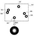
対象画像は図9の202に示すものとし、横1024×縦768画素で1画素当たり輝度は256階調を持つデジタル画像とする。輝度値は、高輝度になるにつれ、大きな数字で表現されるものとする。対象画像202には、ビーズが多数写っており、これらビーズの領域を抽出することを目的とする。 The target image is shown by 202 in FIG. 9, and is a digital image having horizontal 1024 × vertical 768 pixels and luminance per pixel of 256 gradations. The luminance value is expressed by a large number as the luminance increases. The
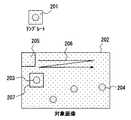
図2は、本実施の形態における画像認識方法での、パターン領域の設定例である。図2において、401は対象画像であるビーズの近傍を拡大したものであり、ビーズ402が暗く写っている。この画像は、紙面の裏側から光を照射した際に撮像した画像であり、ビーズ402はその影を撮影した状態となっている。このとき、照射むら等の影響により、背景部分とビーズ部分の輝度の絶対値は一定しておらず、場所によって異なるが、局所領域においては、背景部分に対してビーズ部分は暗く写っている。 FIG. 2 is a pattern area setting example in the image recognition method according to the present embodiment. In FIG. 2, 401 is an enlarged view of the vicinity of the bead, which is the target image, and the
一方、403はマスクパターンを示す。404〜407は第1のパターン領域であり、408〜411は第2のパターン領域である。また、412は2値化領域である。また、図中、丸印413は1つのビーズの大きさを示した枠である。 On the other hand,
上記第1のパターン領域404〜407は、ビーズ402の内部に含まれる画素を選ぶための領域であり、上記第2のパターン領域408〜411はビーズ402の外部の画素を選ぶための領域である。また、2値化領域412は、ビーズ402の近傍において、該ビーズ402よりもひとまわり大きな領域を設定するためのものである。これら、第1のパターン領域、第2のパターン領域、2値化領域412を合わせて、以下マスクパターンと呼ぶ。 The
マスクパターンは、位置を表わす情報であり、これを対象画像のある位置に重ね合わせたとき、第1のパターン領域、第2のパターン領域、2値化領域412のそれぞれが、対象画像中の特定の領域を指し示すものである。従って、第1のパターン領域、第2のパターン領域、2値化領域412の位置関係は相対的に固定したものであり、それぞれは共通の基準位置からの相対位置で記録されるものとする。 The mask pattern is information representing a position. When this is superimposed on a certain position of the target image, each of the first pattern area, the second pattern area, and the
図2において、紙面横をx座標、縦をy座標とし、第2のパターン領域410に位置する画素を共通の基準位置とした場合、第1のパターン領域407に位置する画素を(3,1),第1のパターン領域405に位置する画素を(1,3),第1のパターン領域406に位置する画素を(5,3),第1のパターン領域404に位置する画素を(3,5)として記憶し、第2のパターン領域は、第2のパターン領域410に位置する画素を(0,0),第2のパターン領域411に位置する画素を(6,0),第2のパターン領域408に位置する画素を(0,6),第2のパターン領域409に位置する画素を(6,6)として記憶し、2値化領域は(2,−1),(3,−1),(4,−1),(1,0),(2,0)・・・として記憶される。以下、このマスクパターンを用いて、対象画像202上を走査しながら基準位置をずらして逐次パターンマッチングを行い、ビーズの画像を抽出する。 In FIG. 2, when the horizontal direction of the paper is the x coordinate, the vertical direction is the y coordinate, and the pixels located in the
以下本発明のパターンマッチングの原理を説明する。本発明では、ビーズの輝度と背景部分の輝度との関係は、必ずビーズの輝度の方が背景部分に比べて所定の閾値Aよりも小さく(暗く)なる。本例では、この閾値Aを100としたが、ビーズの種類や照明条件などによって値を適宜選択すればよい。ここで、マスクパターン403中の413の位置にビーズが存在した場合には(マッチングした場合)、必ず第1のパターン領域は全てビーズの内側に位置する。そのため、第1のパターン領域404〜407に位置する画素の最大値はビーズ内部の画素の輝度のいずれかを示す。一方、第2のパターン領域408〜411は背景部分に位置するため、その位置する画素の最小値は、背景の画素の輝度のいずれかを示す。従って、第1のパターン領域404〜407に位置する画素の最大値をMAX(404〜407)、第2のパターン領域408〜411に位置する画素の最小値をMIN(408〜411)とすると、MIN(408〜411)−MAX(404〜407)≧Aになる。この数式の関係が成立するときにはマッチッングしていると判断する。 The principle of pattern matching according to the present invention will be described below. In the present invention, the relationship between the luminance of the beads and the luminance of the background portion is always smaller (darker) than the predetermined threshold A in the luminance of the beads compared to the background portion. In this example, the threshold A is set to 100. However, the value may be appropriately selected depending on the type of beads, illumination conditions, and the like. Here, when a bead exists at the
現実的には、ビーズの輝度と背景部分の輝度との差にはばらつきがあるため、両者の差がほぼ100であった場合には、閾値Aにはその半分の50という値を用いれば、MIN(408〜411)−MAX(404〜407)≧Aの式は必ず成立することになる。 Actually, since the difference between the luminance of the beads and the luminance of the background portion varies, when the difference between the two is almost 100, if the value of 50, which is half of the threshold A, is used, The expression of MIN (408 to 411) −MAX (404 to 407) ≧ A always holds.
また、マスクパターン403中の413の位置にビーズが存在しない場合や、位置がずれている場合は(マッチングしていない場合)、第1のパターン領域中に背景部分が含まれるか、あるいは第2のパターン領域中にビーズ部分が含まれるため、MAX(404〜407)が背景の輝度を示すかあるいはMIN(408〜411)がビーズの輝度を表すこととなり、MIN(408〜411)−MAX(404〜407)<Aとなる。従って、この場合にはマッチングしていないと判断する。 Further, when a bead is not present at the
以下、パターンマッチングを行う手順について示す。マスクパターン403を対象画像202のある位置に重ね合わせたものと仮定し、その位置において、MAX(404〜407)とMIN(408〜411)を求める。 Hereinafter, a procedure for performing pattern matching will be described. Assuming that the
次に、MIN(408〜411)−MAX(404〜407)を計算し、その結果を閾値Aと比較する。MIN(408〜411)−MAX(404〜407)≧Aの場合は、マッチングしていると判断し、MIN(408〜411)−MAX(404〜407)<Aの場合は、マッチングしていないと判断する。 Next, MIN (408-411) -MAX (404-407) is calculated, and the result is compared with the threshold A. If MIN (408-411) -MAX (404-407) ≧ A, it is determined that there is a match. If MIN (408-411) -MAX (404-407) <A, there is no matching. Judge.
以上のマッチング処理を、対象画像202に対してマスクパターン403の位置をずらして繰り返し、対象画像202全体において走査することにより、対象画像202に含まれるビーズの位置を抽出することができる。 By repeating the above matching processing while shifting the position of the
次に図1を用いて、本発明の実施の形態1における画像処理装置の構成について示す。図1において、101はマッチング処理を行うべき対象画像である。この対象画像101に対してマスクパターンを用いたマッチングを行う際に、対象画像に対してマスクパターンは小さいため、マスクパターンを重ねる位置を、対象画像中において走査しながら(マスクパターンの基準位置を対象画像中においてずらしながら)、マスクパターンを重ねた小領域毎に個別にマッチングを行う必要がある。このため、走査回路102により、対象画像中101の評価位置を指定し、部分画像切り出し回路103により、その指定位置における小領域を切り出す。小領域において、第1のパターン領域104を重ね合わせ、第1のパターン領域104に含まれる対象画像の画素のうち最大のものを、最大値検出回路105により求める。同様に、小領域に第2のパターン領域106を重ね合わせ、第2のパターン領域106に含まれる対象画像の画素のうち最小のものを、最小値検出回路107により求める。 Next, the configuration of the image processing apparatus according to Embodiment 1 of the present invention will be described with reference to FIG. In FIG. 1,
差分回路108では、この最小値から最大値を引くことで差分を求め、この値と判定閾値109とを比較回路110により比較する。比較の結果、差分のほうが小さい場合は、パターンが存在しないものと判断し、これ以上の処理は行わない。一方、比較の結果、差分のほうが大きい場合は、パターンが存在するものと判断し、2値化の処理を行う。2値化のための閾値は、最大値検出回路105の出力と、最小値検出回路107の出力とを、平均化回路111により平均化したものである。 The
2値化領域112に定義された範囲の画素は、2値化回路113において、閾値と比較し、閾値よりも小さな輝度を持つ画素が、目的とする検出対象の部分となるため、この画素を0とし、それ以外の画素は255とする。これらの流れを、走査回路102により認識判定の位置をずらしながら、対象画像101全体に対して行うことで、目的とする検出対象のみが0となり、その他の部分は255となった2値化結果を得ることができる。 Pixels in the range defined in the
図2の認識対象402においては、従来では2値化領域412の全領域が、例えば、61画素であるとすると、61回の減算、61回の乗算、1回の加算からなる演算が必要であるが、本実施の形態では、第1パターン領域が4画素分、第2のパターン領域が4画素分であるため、各領域での最大、または最小を求めるための比較の演算が4−1=3回、すなわち減算が3×2回=6回であり、これの大小関係を求める減算が1回と、合計7回の減算からなる演算により達成することができ、123−7=116回(約93パーセント)の演算を削減することができることになる。 In the
このように本実施の形態1にかかる画像認識方法及び画像認識装置によれば、低輝度領域、高輝度領域、2値化領域のマスクを用い、低輝度領域における最も明るい画素が、高輝度領域における最も暗い画素よりもさらに暗い場合には、対象物が検出されたものとして認識するようにしたので、x×y画素からなる画像を検査する際に、(x×y+1)回の演算で処理を終了することができ、演算回数を大幅に削減することができるとともに、画像中から所望のパターンを確実に抽出することができる。 As described above, according to the image recognition method and the image recognition apparatus according to the first embodiment, the brightest pixel in the low luminance region is the high luminance region using the mask of the low luminance region, the high luminance region, and the binarized region. When the image is darker than the darkest pixel in the image, the object is recognized as being detected. Therefore, when an image consisting of x × y pixels is inspected, the processing is performed by (x × y + 1) times. And the number of operations can be greatly reduced, and a desired pattern can be reliably extracted from the image.
(実施の形態2)
次に本発明の実施の形態2にかかる画像認識方法及び画像認識装置について説明する。上記実施の形態1により、本発明の概念的な構成及び動作について説明したが、次に、より具体的な実施の形態について示す。(Embodiment 2)
Next, an image recognition method and an image recognition apparatus according to the second embodiment of the present invention will be described. Although the conceptual configuration and operation of the present invention have been described in the first embodiment, a more specific embodiment will be described next.
図3は対象画像を示したものである。図3上部は顕微鏡により撮影した対象画像501であり、内部に複数のビーズが写っている。この対象画像501は、紙面横640画素、縦480画素で、0〜255の256階調をもつものとする。画像の座標系は、紙面左上隅を(0,0)とし、右方向がx軸のプラス方向、下方向がy軸のプラス方向とする。このため、紙面右下の画素を座標で表わすと、(639,479)となる。 FIG. 3 shows a target image. The upper part of FIG. 3 is a
現実の対象画像においては数百のビーズが写っているが、この例の対象画像501においては説明を簡単にするために、502〜507の6個のビーズが写っているものとする。図3の紙面下部に1つのビーズを拡大したものを示しているが、ビーズは中央部に非常に明るい領域を持っている。これは、ビーズが半透明なアクリルでてきているため、背景から光を当てた場合には、レンズの働きを示し、中央部分に集光して中央が非常に明るくなるからである。また、ビーズ周縁部分は光が曲げられて届かないため、非常に暗いものとなる。 In the actual target image, several hundred beads are shown, but in the
この対象画像501に対して、画像処理により行うべき内容は、ビーズの全数をカウントすることと、独立したビーズのビーズ内領域を求めることの2つである。独立ビーズとは、他のビーズから一定距離以上離れているビーズを意味し、図5においては、502、507のビーズを指す。ビーズ503と504は接しているため、独立ビーズとはならず、ビーズ506と507は互いの距離が近いため、やはり独立ビーズとはならない。 The contents to be performed by the image processing on the
この例では、全てのほかのビーズから2画素以上離れているものを独立ビーズと呼ぶこととする。 In this example, those that are two pixels or more away from all other beads are referred to as independent beads.
まず、ビーズの全数をカウントする場合には、ビーズ中央の高輝度領域がビーズ周縁部分よりも明るいことを利用する。図4はビーズをカウントするためのマスクパターンを示すものである。図4において、601は、ビーズが本マスクパターンの位置に一致した時の外形状を示している。602〜609は第1のパターン領域であり、ビーズの周縁部分の位置に設定している。また、610〜613は第2のパターン領域であり、ビーズの中央部の位置に設定している。処理を行う上での基準として、第2のパターン領域610に位置する画素をマスクパターンの基準位置とし、第1のパターン領域602〜609を上記第2のパターン領域610に位置する画素からの相対位置として記憶し、第2のパターン領域610〜613を上記第2のパターン領域610に位置する画素610からの相対位置として記憶する。すなわち、第1のパターン領域602は(−2,0)、第1のパターン領域603は(0,−2)、第1のパターン領域604は(1,−2)、第1のパターン領域605は(3,0)、第1のパターン領域606は(3,1)、第1のパターン領域607は(1,3)、第1のパターン領域608は(0,3)、第1のパターン領域609は(−2,1)で表現し、第2のパターン領域の610は(0,0)、611は(1,0)、612は(1,1)、613は(0,1)で表現する。 First, when counting the total number of beads, the fact that the high brightness area at the center of the bead is brighter than the peripheral part of the bead is used. FIG. 4 shows a mask pattern for counting beads. In FIG. 4,
対象画像におけるマッチング処理を行う際には、対象画像に本マスクパターン領域を重ねて、第1のパターン領域および第2のパターン領域の輝度値を基に判定し、これを対象画像に対してマスクパターンの基準位置を1画素ずらしながら順次判定を行って行く。このときの手順を、順を追って説明する。 When matching processing is performed on the target image, this mask pattern region is overlaid on the target image, and determination is made based on the luminance values of the first pattern region and the second pattern region, and this is masked against the target image. The determination is sequentially performed while shifting the reference position of the pattern by one pixel. The procedure at this time will be described step by step.
まず、マスクパターン領域を対象画像501内において紙面左上隅に配置する。マスクパターン領域が対象画像501からはみ出さないように配置するためには、マスクパターン領域の基準位置である領域610が対象画像501の座標(2,2)と重なるように配置する。本位置におけるマッチング処理が終了した後には、マスクパターン領域を対象画像501に対して1画素紙面右に移動する。すなわち、マスクパターン領域の基準位置である610が対象画像501の座標(3,2)と重なるように配置する。この状態で同様にマッチング処理を行い、以下同様に、順次マスクパターン領域を対象画像501に対して1画素右に移動してマッチング処理を行う。これを繰り返して、マスクパターン領域の基準位置である610が対象画像501の座標(636,2)と重なるように配置してマッチング処理を行った後は、ここからさらに右に配置した場合にはマスクパターン領域が対象画像501からはみ出すことにななるため、マスクパターン領域を紙面左に戻し、且つ1画素下にずらして、対象画像501の座標(2,3)に配置する。以下、同様の処理を行い、マスクパターン領域の基準位置である610が対象画像501の座標(636,476)と重なるように配置してマッチング処理を行うまで、走査しつつマッチング処理を繰り返す。 First, the mask pattern area is arranged in the upper left corner of the drawing in the
次に、各位置におけるマッチング方法の手順を説明する。マスクパターン領域の基準位置である610を対象画像501の(x,y)位置に重ねてマッチングする場合、この位置において、第1のパターン領域である602の、対象画像501における座標は、基準位置610の対象画像における座標(x,y)と、基準位置からの602の座標(−2,0)を座標成分ごとに加算することにより、(x−2,y)として求めることができる。この座標における対象画像501の輝度値を602xyとする。同様の手順により、第1のパターン領域である603〜609の位置における対象画像501の画素の輝度値を603xy〜609xyとする。輝度値602xy〜609xyの中の最大のものをMAX(602xy〜609xy)とする。 Next, the procedure of the matching method at each position will be described. When matching is performed by superimposing the
次に、第2のパターン領域についても同様に、610の対象画像501における座標は、基準位置610の対象画像における座標(x,y)と、基準位置からの602の座標(0,0)を座標成分ごとに加算することにより、(x,y)として求めることができる。この座標における対象画像501の輝度値を610xyとする。同様の手順により、第2のパターン領域である610〜613位置における対象画像501の画素の輝度値をそれぞれ610xy〜613xyとして求める。輝度値610xy〜613xyの中の最小のものをMIN(610xy〜613xy)とする。以上により求めた値を用いて、MIN(610xy〜613xy)−MAX(602xy〜609xy)により求めた差分値が、特定のオフセット量(=A)以上である場合には、ビーズが存在するものと判定する。このときの判定基準となるオフセット量Aは、次のように求めるものとする。 Similarly, for the second pattern region, the coordinates of the
図5は対象画像の輝度分布を示したものである。紙面横軸が輝度値を表わし、左が低輝度、右が高輝度を表わす。紙面縦軸は各輝度における画素の総数を示している。図5において、701はビーズの中心部の画素が分布している領域であり、一般的には非常に明るいことから輝度的に飽和しており、最高輝度の部分に分布している。702は背景となっている部分の画素が分布している領域であり、この部分の画素が最も多くなっている。703はビーズの周縁部分となっている部分の画素が分布している領域である。本来、ビーズの周縁部分とビーズの中心部のオフセット量は領域701と領域703の輝度値の差分を元に求めることが望ましい。しかし、実際の対象画像では、図5のように3つの山ができる場合だけではなく、連続的な変化により谷の部分が判別できない場合もあり得ることから、703の位置を求めることが困難な場合が存在する。一方、位置702および位置703の関係は、光の強さに応じて変化するものの、その比率は一定であり、702の位置を求めることで間接的に703の位置を求めるものとする。すなわち、702の位置は、ヒストグラムが最大となる位置であるため、対象画像全体のヒストグラムを作った後、その最大頻度の位置を702の位置として求める。求めた702の位置における輝度値をBとする。703の位置は経験的に702の位置の2/5の位置であることがわかっているため、703の輝度値は、2/5*Bとなる。また、701の位置は、多くの場合は飽和しており、最大輝度であるが、そうでない場合もありえるため、高輝度部からヒストグラムの頻度を加算していき、全体の0.5%となる輝度を701の輝度Cとする。 FIG. 5 shows the luminance distribution of the target image. The horizontal axis of the drawing represents the luminance value, the left represents low luminance, and the right represents high luminance. The vertical axis of the drawing indicates the total number of pixels at each luminance. In FIG. 5,
別の表現をすると、ヒストグラムの下部分の面積において、高輝度側の面積が全体面積の0.5%となる点を輝度Cとする。ビーズ内部の高輝度部と低輝度部の差は、C−2/5*Bで求められ、オフセット量Aとしてはマージンを見て、A=1/2*(C−2/5*B)を用いるものとする。 In other words, the luminance C is a point where the area on the high luminance side is 0.5% of the total area in the area of the lower part of the histogram. The difference between the high-intensity part and the low-intensity part inside the bead is obtained by C-2 / 5 * B. As the offset amount A, looking at the margin, A = 1/2 * (C-2 / 5 * B) Shall be used.
上記手法を用いて、マスクパターンを1画素ずつずらして判定を行い、ビーズの有無の判定を行って行く。このとき、ある位置でビーズが存在するものと判定しても、1画素ずらした状態でもう一度判定を行った場合は、マスクパターンの位置が先程と非常に近いため、判定条件が成立して、再びビーズが存在するものと判定することがある。これは同一ビーズで判定条件が成立したものであり、これを別のビーズとしてカウントした場合には、ビーズの総数を間違えることとなる。このため、これら重複カウントを防ぐために、ビーズが存在するものと判定した位置から、縦4画素、横4画素の範囲内においては、判定を行わないようにする。すなわち、ビーズが存在するものと判定したマスクパターンの基準位置から、縦4画素、横4画素の正方領域にマーキングし、マスクパターンの基準位置をずらした際に、マスクパターンの基準位置に対応する画素にマーキングがなされていた場合には判定を行わないものとする。以上の手順を取り、対象画像の全領域において判定を行い、ビーズが存在するものと判定する毎にカウンタを1つずつ増やすことにより、対象画像内に含まれる全ビーズの数を得ることができる。 Using the above method, the determination is made by shifting the mask pattern pixel by pixel, and the presence or absence of beads is determined. At this time, even if it is determined that a bead exists at a certain position, if the determination is performed again with a shift of one pixel, the determination condition is satisfied because the position of the mask pattern is very close to the previous position. It may be determined that beads are present again. This is because the determination condition is established with the same bead, and when this is counted as another bead, the total number of beads is wrong. Therefore, in order to prevent these overlap counts, the determination is not performed within the range of 4 pixels in the vertical direction and 4 pixels in the horizontal direction from the position where it is determined that the beads are present. That is, when a square area of 4 pixels in the vertical direction and 4 pixels in the horizontal direction are marked from the reference position of the mask pattern determined to have beads, and the reference position of the mask pattern is shifted, it corresponds to the reference position of the mask pattern. If the pixel has been marked, no determination is made. By taking the above procedure, making a determination in the entire region of the target image, and incrementing the counter by one each time it is determined that a bead exists, the number of all beads included in the target image can be obtained. .
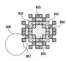
次に、対象画像501に対して、画像処理により行うべきもう1つの内容であるところの、独立したビーズの領域を求める方法について、図6を用いて説明を行う。図6は独立したビーズを検出するためのマスクパターンを示したものであり、ここではビーズ間が1画素以上離れたビーズのみを検出できるようにしたものである。図6において、801は仮想的に示したビーズの外形状である。802は第1のパターン領域である。図において802の引出し線で指した部分と同じハッチングで示した領域は、全て第1のパターン領域である。同様に、803は第2のパターン領域である。また、804は2値化領域であり、805は後述する固定値領域である。対象画像は256階調であるが、これから、独立ビーズの領域が1、それ以外の領域が0で表わされる2値の結果画像を作ることを目的としている。結果画像には、最初全て0を代入しておくものとする。また、802の引出し線で指した画素をマスクパターン基準位置とし、全てのマスクパターンの画素についてはマスクパターン基準位置からの相対位置で記憶するものとする。2値化においては、対象画像に本パターン領域を重ねて、第1のパターン領域および第2のパターン領域の輝度値を元にマッチング処理を行い、独立ビーズが存在しないと判定したときは結果画像には何も行わず、独立ビーズが存在したと判定した場合には結果画像に2値化結果を書き込む。以上のような処理を対象画像に対して、マスクパターンの基準位置を1画素ずらしながら順次行って行く。判定方法としては、第2のパターン領域に含まれる輝度のうち最小のものから、第1のパターン領域に含まれる輝度のうち最大のものを減じた差分値が、特定のオフセット量以上となる場合には、独立ビーズが存在するものと判定する。オフセット量は、背景とビーズ周縁部の輝度差を判別できる大きさに設定する。ここでは、図5において、ヒストグラムの最大値702が背景部の輝度値であり、この輝度値をAとする。ビーズ周縁部の輝度値703の位置は経験的に2/5*Aとなることから、両者の差はA−2/5*A=3/5*Aであり、マージンを見て3/10*Aを、ここでのオフセット量とする。 Next, a method for obtaining an independent bead region, which is another content to be performed on the
本方法によれば、例えば、ビーズの位置が801にあるときは、第1のパターン領域802は全てビーズの周縁部となり、この中の最も明るい画素でも全体でみると非常に暗いものとなる。一方、第2のパターン領域803は、周囲に他のビーズが存在しない場合は、背景部分であり、この中の最も暗い画素でも、全体で見ると比較的明るいものとなる。このため、独立ビーズ存在のための判定条件が成り立つ。また、例えば、806の位置に他のビーズが存在した場合には、画素807がビーズ周縁部分となる。このため、第2のパターン領域803に含まれる輝度のうち最小のものは画素807の輝度となり、第1のパターン領域802の輝度とほぼ同じ輝度となることから、両者にオフセット量の違いは現われず、独立ビーズが存在しない、という判定を行なうこととなる。 According to this method, for example, when the position of the bead is at 801, the
独立ビーズが存在すると判定された場合は、2値化の処理を行う。先ず、固定値領域805および第1のパターン領域802に対応する位置の結果画像の画素には、無条件に1を書き込む。次に、第1のパターン領域802に含まれる輝度のうち最大のものと、第2のパターン領域803に含まれる輝度のうち最小のものとの、中央値を2値化の閾値として求める。2値化領域804では、各画素において、その輝度値と2値化の閾値とを比較し、2値化の閾値よりも小さな輝度値をもつ画素に対応する位置の結果画像の画素には、1を書き込む。以上により、内部は全て1で表現され、境界部分は閾値判定により2値化された結果画像を得ることができる。また、独立ビーズ存在のマッチング処理を行う前に、マスクパターンの基準位置における結果画像の値が1であるとき、判定を行わずに、次の位置に移動するようにすることで、同じビーズでの2度判定を防止することができ、処理速度を向上させることができる。 If it is determined that independent beads are present, binarization processing is performed. First, 1 is unconditionally written to the pixels of the result image at positions corresponding to the fixed
本手法においては、マスクパターンの形状の設定が認識の精度に大きな影響を与えるため、これらの形状を適切に設定することが重要となる。このため、マスクパターン各要素であるところの、第1のパターン領域802、第2のパターン領域803、2値化領域804、固定値領域805の設定を容易にするマンマシンインタフェースについて以下に説明する。 In this method, since the setting of the shape of the mask pattern has a great influence on the recognition accuracy, it is important to set these shapes appropriately. Therefore, a man-machine interface that facilitates setting of the
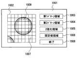
本システムは、パソコンのモニタ画面上に各種画像を表示して、これをマウスでクリックしながらマスクパターンの形状を設定して行くものである。図8はマスクパターン作成画面のイメージ図を示す。図8において、モニタ画面1001に操作画面が表示されている。操作画面は、編集領域1002、第1パターン領域設定ボタン1003、第2パターン領域設定ボタン1004、2値化領域設定ボタン1005、固定値領域設定ボタン1006および終了ボタン1008よりなる。 This system displays various images on the monitor screen of a personal computer, and sets the shape of the mask pattern while clicking with the mouse. FIG. 8 shows an image diagram of the mask pattern creation screen. In FIG. 8, an operation screen is displayed on the
第1のパターン領域を設定したい場合は、第1パターン領域設定ボタン1003をマウスでクリックすると、第1のパターン領域設定モードとなり、この状態において編集領域1002の1つの格子枠1007をクリックすると、格子枠1007は、例えば赤で塗りつぶされる。同様に、第1のパターン領域を設定したい格子枠をマウスでクリックすることで、次々に第1のパターン領域を設定することができる。次に、第2のパターン領域を設定したい場合は、第2パターン領域設定ボタン1004をマウスでクリックすると、第2のパターン領域設定モードとなり、この状態において編集領域1002の1つの格子枠をクリックすると、その格子枠は、例えば青で塗りつぶされる。同様に、2値化領域、固定値領域についても、マウスにより位置を指定することにより、異なる色で表示し、マスクパターンを視覚的に確認することができるようにしている。全てのマスクパターンの編集が終了したら、終了ボタン1008を押すことにより、編集された各マスクパターンの位置情報を記憶する。 To set the first pattern area, click the first pattern
本編集を行う上において、マスクパターンを設定する際に、対象画像を参照しながら行なうと容易に行うことができる。すなわち、図6において、対象画像上のビーズ801に重ねて、マスクパターン各要素802〜805を指定していくことができれば、各マスクパターンの位置関係を確実に設定することができる。このため、まず、ユーザーが対象画像のうち、参照したい領域をマウスで指定すると、その部分の対象画像を拡大し、図8の編集領域1002の部分にオーバレイし、参照画像1009として表示する。ここでは、参照画像1009は白黒256階調により表示するものとする。先述したように、ユーザが第1のパターン領域を設定したいときは、マウスで第1のパターン領域設定ボタン1003を選択し、第1のパターン領域設定モードとなったときは、以降でクリックされた格子枠は、例えば赤色として表示しても良いが、赤で塗りつぶした場合には、クリックされた格子枠が増えるに従って、参照画像が隠されることとなる。このため、ここでは、完全に赤色に置き換えるのではなく、輝度を参照画像のままに保ったまま、色差のみを赤くする。すなわち、輝度成分(明るさ)を参照画像のままに保ち、色差(色合い)のみをマスクパターンの要素に応じたものとして表示する。 When performing this editing, it is easy to set the mask pattern while referring to the target image. That is, in FIG. 6, if the
この変換のための演算手順を以下に示す。参照画像の画素は白黒であることから、元の階調がR(赤成分)=G(緑成分)=B(青成分)=Xであるものとする。人間の目に感じる輝度は、0.3R+0.6G+0.1Bであることから、変換後のR、G、Bは、0.3R+0.6G+0.1B=Xの関係を保つ必要がある。また、できるだけ、赤に近い色成分を持たせるために、R−Xをできるだけ大きくするように設定する。 The calculation procedure for this conversion is shown below. Since the pixels of the reference image are black and white, it is assumed that the original gradation is R (red component) = G (green component) = B (blue component) = X. Since the luminance perceived by the human eye is 0.3R + 0.6G + 0.1B, R, G, and B after conversion must maintain the relationship of 0.3R + 0.6G + 0.1B = X. In order to have a color component as close to red as possible, RX is set to be as large as possible.
また、GとBは同じ値となるようにする。この関係から、Xが76以下である場合には、R=X/0.3、G=B=0であり、Xが77以上である場合には、R=255、G=B=(X−76.5)/0.7で求めることができる。以上により、第1のパターン領域として設定された格子枠には、ここで示した方法により求めたR、G、Bを用いることで、輝度成分を参照画像に保ったまま、色差成分のみを変えて表示することが可能となる。 G and B are set to the same value. From this relationship, when X is 76 or less, R = X / 0.3 and G = B = 0, and when X is 77 or more, R = 255, G = B = (X -76.5) /0.7. As described above, the R, G, and B obtained by the method shown here are used for the lattice frame set as the first pattern region, so that only the color difference component is changed while keeping the luminance component in the reference image. Can be displayed.
同様に、他のマスクパターンを設定する際に、マウスでクリックされた位置を表示するために、パターン領域2は、R−Xをできるだけ小さく、2値化領域はB−Xをできるだけ大きく、固定値領域はB−Xをできるだけ小さくするようにRGBを求め、これを表示することで、参照画像を確認しつつ、各マスクパターンを設定することが可能となる。 Similarly, when setting another mask pattern, in order to display the position clicked with the mouse, the pattern area 2 is as small as RX and the binary area is as large as BX as fixed. In the value area, RGB is obtained so as to make BX as small as possible, and this is displayed, so that each mask pattern can be set while checking the reference image.
このように本実施の形態2にかかる画像認識方法及び画像認識装置によれば、全てビーズの周縁部となる第1のパターン領域802と、周囲に他のビーズが存在しない場合に背景部分となる第2のパターン領域803と、第1のパターン領域802と第2のパターン領域803との間に位置する2値化領域804と、ビーズの中心部となる固定領域805とからなるマスクパターンを用いて、ビーズの有無の判定を行なうようにしたので、ビーズが隣接して存在する場合においても、複数のビーズが隣接して存在するのを正確に判断してビーズの総数を正確に数えることができる。 As described above, according to the image recognition method and the image recognition apparatus according to the second embodiment, the
(実施の形態3)
次に本発明の実施の形態3にかかる画像認識方法及び画像認識装置について説明する。
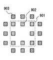
上記各実施の形態では、判別対象となるものの形状が丸い形状のものについてのパターン存在判定方法について示したが、その他の形状に対する存在判定方法について、以下図を用いて説明する。図7は判別対象となるものが正方形のものを検出するために用いるマスクパターンを示したものである。901は判別対象となる正方形の概形であり、902の引出し線で指した部分と同じハッチングで示した領域は、全て第1のパターン領域である。同様に、903は第2のパターン領域である。(Embodiment 3)
Next, an image recognition method and an image recognition apparatus according to the third embodiment of the present invention will be described.
In each of the above-described embodiments, the pattern presence determination method for a round shape is shown, but the presence determination method for other shapes will be described below with reference to the drawings. FIG. 7 shows a mask pattern used for detecting a square object to be discriminated.
判別対象に特定のパターンが存在するかいなかの判定においては、上記実施の形態と同様に、第1のパターン領域902に含まれる輝度のうち最大のものよりも、第2のパターン領域903に含まれる輝度のうち最小のものが、特定のオフセット量以上の差をつけて大きい場合には、パターンが存在するものと判定する。ただし、正方形のパターンの場合、対象画像中の正方形が、マスクパターンのパターン領域の角度に対して回転している場合には、マスクパターンでは正確な判定が行えない。このため、同じ位置に置いて、本マスクパターンを回転させ、各種角度で存在判定を繰り返し行う必要がある。 In determining whether or not a specific pattern exists in the determination target, the luminance is included in the
実際の処理では、第1のパターン領域902と第2のパターン領域903とは概形状901から余裕を持って設定しているため、15度刻みに6回繰り返せばよい。また、処理速度向上のためには、あらかじめ15度ずつ回転した6個のマスクパターンを準備しておき、1個所につき6個のマスクパターンにおいてパターン存在判定を行い、1つでも存在判定の条件を満たした場合には、その位置にパターンが存在すると判定することができる。 In actual processing, since the
このように本実施の形態3にかかる画像認識方法及び画像認識装置によれば、円形以外の認識対象物に対して、矩形の認識対象物にはその形状に合わせた複数の領域パターンよりなるマスクパターンを用いて、認識を行なうようにしたので、円形以外の認識対象物についても、これを高い精度で高速に検出することができる。 As described above, according to the image recognition method and the image recognition apparatus according to the third embodiment, for a recognition object other than a circle, a rectangular recognition object has a mask made up of a plurality of area patterns matched to the shape. Since recognition is performed using a pattern, it is possible to detect a recognition object other than a circle at high speed with high accuracy.
また、矩形の場合にはマスクパターンを所定の角度回転させて認識を行なうことで、認識対象物が所定の角度で位置しない場合においても、これを精度良く認識することができる。 In the case of a rectangle, the recognition is performed by rotating the mask pattern by a predetermined angle, so that even when the recognition object is not positioned at the predetermined angle, this can be recognized with high accuracy.
なお、上記各実施の形態において、パターン存在判定を行う対象物の大きさが複数ある場合においても、マスクパターンを拡大/縮小しながら判定したり、予め種々の大きさで作成した複数のマスクパターンを順次用いて判定を行うことにより、パターン存在判定を行うことができる。 In each of the above embodiments, even when there are a plurality of sizes of objects to be subjected to pattern existence determination, a mask pattern is determined while being enlarged / reduced, or a plurality of mask patterns created in various sizes in advance. The pattern presence determination can be performed by sequentially determining using.
さらに、対象画像に多くのノイズが含まれている場合には、上記各実施の形態による方法ではノイズの影響によりパターンが存在している場合にも、パターンが存在しないという判定となるおそれがある。このような場合には、第1のパターン領域902に含まれる対象画像データの輝度の平均値よりも、第2のパターン領域903に含まれる対象画像データの輝度の平均値の方が、特定のオフセット量以上の差をつけて大きな値となるときに、対象画像データ中の当該位置に特定の画像パターンが存在するものと判定するようにすることで、検出漏れを防止することが可能となる。 Furthermore, when the target image includes a lot of noise, the method according to each of the above embodiments may determine that the pattern does not exist even when the pattern exists due to the influence of noise. . In such a case, the average luminance value of the target image data included in the
また、上記各実施の形態において、第1のパターン領域に含まれる対象画像データの輝度の最大値よりも、第2のパターン領域に含まれる対象画像データの輝度の最小値の方が、所定の閾値よりも大きな値となり、且つ、第1のパターン領域に含まれる対象画像データの輝度の平均値よりも、第2のパターン領域に含まれる対象画像データの輝度の平均値の方が、所定の閾値よりも大きな値となるときに、対象画像データ中の当該位置に特定の画像パターンが存在するものと判定することで、より確実な判定が可能となる。 In each of the above embodiments, the minimum luminance value of the target image data included in the second pattern area is greater than the predetermined maximum luminance value of the target image data included in the first pattern area. The average value of the luminance of the target image data included in the second pattern region is larger than the average value of the luminance of the target image data included in the first pattern region. When the value is larger than the threshold value, it is possible to make a more reliable determination by determining that a specific image pattern exists at the position in the target image data.
本発明にかかる画像処理方法及び画像認識装置は、パターン認識を必要とする各種処理装置に有用であり、特に、顕微鏡画像中の測定対象のカウント、対象領域の抽出を容易に行えることから、これらバイオ解析装置に有効である。 The image processing method and the image recognition apparatus according to the present invention are useful for various processing apparatuses that require pattern recognition, and in particular, since the measurement target in the microscope image and the extraction of the target area can be easily performed, Effective for bioanalytical devices.
105 最大値検出回路
106 第2パターン領域
107 最小値検出回路
108 差分回路
109 判定閾値
110 比較回路
111 平均化回路
112 2値化領域
113 2値化回路
114 2値化結果
201 テンプレートマッチング用テンプレート画像
202 対象画像
203〜204 検出対象
205 最初のパターンマッチング位置
206 パターンマッチングの走査経路
207 パターンを検出した位置
301 差分演算
302 2乗加算
303 相関閾値
304 比較器
305 判定結果
401 デジタル化された対象画像
402 認識対象
403 マスクパターン
404〜407 第1パターン領域
408〜411 第2パターン領域
412 2値化領域
413 認識対象の概形状
501 対象画像
502〜507 検出すべきビーズ
601 ビーズの概形状
602〜609 第1パターン領域
610〜613 第2パターン領域
701 ビーズ中央部の輝度
702 背景部の輝度
703 ビーズ周縁部の輝度
801 ビーズの概形状
802 第1パターン領域
803 第2パターン領域
804 2値化領域
805 固定値領域
806 隣接したビーズの概形状
807 隣接したビーズに含まれる画素
901 検出対象の概形状902 第1パターン領域
903 第2パターン領域
1001 モニタ画面
1002 編集領域
1003 第1パターン指定ボタン
1004 第2パターン指定ボタン
1005 2値化領域指定ボタン
1006 固定値領域指定ボタン
1007 クリックされた格子枠
1008 終了ボタン
1009 オーバレイされた参照画像105 Maximum
Claims (17)
Translated fromJapanese前記マスクパターンは、前記認識すべき画像よりも小さく且つ中心部には存在しない低輝度領域用の第1のパターン領域と、前記第1のパターン領域の外側に前記認識すべき画像よりも大きく且つ隣接する他の認識すべき画像との予め定められた距離より小さい高輝度領域用の第2のパターン領域とを持ち、前記第1のパターン領域に囲まれた領域を固定値領域、前記第1のパターン領域と第2のパターン領域とに挟まれた領域を2値化領域とし、
前記第1のパターン領域から、前記対象画像データの最大輝度を示す第1の代表値を得る工程と、
前記第2のパターン領域から、前記対象画像データの最小輝度を示す第2の代表値を得る工程と、
前記第2の代表値から前記第1の代表値を引いた差分値が前記対象画像データの輝度ヒストグラムの最大輝度値が3/10以上であるとき、前記対象画像の内部に認識すべき孤立画像が存在すると判定する工程と、
前記対象画像の内部に認識すべき孤立画像が存在すると判定したときに前記2値化領域内の対象画像データを所定の閾値と比較して2値化する工程とを、
含むことを特徴とする画像認識方法。A target image having a mask pattern indicating the characteristics of an image pattern to be recognized, and having a plurality of images to be recognized having the same shape and dimensions having a gradation of two or more values digitized using the mask pattern An image recognition method for recognizingan isolated image isolated from data,
The mask pattern is smaller than the image to be recognized and is larger than the image to be recognized outside the first pattern region, and a first pattern regionfor a low-luminance region that does not exist in the center portion and A second pattern regionfor a high-intensity region smaller than a predetermined distance from another adjacent image to be recognized, and a region surrounded by the first pattern region is a fixed value region, the first region A region sandwiched between the pattern region and the second pattern region is a binarized region,
Obtaining a first representative value indicating the maximum luminance of the target image data from the first pattern region;
Obtaining a second representative value indicating a minimum luminance of the target image data from the second pattern region;
Anisolated image to be recognized inside the target image when a difference value obtained by subtracting the first representative value from the second representative value hasa maximum luminance value of 3/10 or more ofthe luminance histogram of the target image data. Determining that exists,
A step of binarizing the target image data in the binarized area by comparing with a predetermined threshold when it is determined that there is anisolated image to be recognized inside the target image;
An image recognition method comprising:
前記所定の閾値は、第1のパターン領域における前記対象画像データの輝度の代表値と、第2のパターン領域における前記対象画像データの輝度の代表値との、中間値とする、
ことを特徴とする画像認識方法。The image recognition method according to claim1 ,
The predetermined threshold value is an intermediate value between a representative value of luminance of the target image data in the first pattern region and a representative value of luminance of the target image data in the second pattern region.
An image recognition method characterized by the above.
前記所定の閾値は、第1のパターン領域に含まれる対象画像データの輝度の最大値と、第2のパターン領域に含まれる対象画像データの輝度の最小値との、中間値とする、
ことを特徴とする画像認識方法。The image recognition method according to claim1 ,
The predetermined threshold is an intermediate value between the maximum value of the luminance of the target image data included in the first pattern area and the minimum value of the luminance of the target image data included in the second pattern area.
An image recognition method characterized by the above.
前記対象画像の内部に認識すべき画像が存在すると判定したときに、前記固定値領域内の対象画像データを、2値のうち予め定めた片一方の値として2値化する、
ことを特徴とする画像認識方法。The image recognition method according to claim1 ,
When it is determined that there is an image to be recognized inside the target image, the target image data in the fixed value region is binarized as one of predetermined values of the two values.
An image recognition method characterized by the above.
2値化されない部分については、2値のうち、予め定めた片一方の値とし、画像全体の2値化結果を得る、
ことを特徴とする画像認識方法。The image recognition method according to anyone of claims1 to4 ,
For a portion that is not binarized, one of the two values is determined in advance, and a binarized result of the entire image is obtained.
An image recognition method characterized by the above.
前記第1のパターン領域および第2のパターン領域を画面上に表示する手段と、により、前記画面上において第1のパターン領域および第2のパターン領域の各画素の位置を決定するための位置指定手段と、
を備えたことを特徴とする画像認識装置。In the image recognition apparatus which processes an image using the image recognition method of Claim1 ,
Position designation for determining the position of each pixel in the first pattern area and the second pattern area on the screen by means for displaying the first pattern area and the second pattern area on the screen Means,
An image recognition apparatus comprising:
前記第1のパターン領域および第2のパターン領域を決定する際に、表示した対象画像データの画像に第1のパターン領域および第2のパターン領域をオーバレイ表示して、前記第1のパターン領域および第2のパターン領域を編集する手段を、
備えたことを特徴とする画像認識装置。The image recognition apparatus according to claim6 .
When determining the first pattern area and the second pattern area, the first pattern area and the second pattern area are displayed in an overlay on the displayed image of the target image data, and the first pattern area and the second pattern area are displayed. Means for editing the second pattern region;
An image recognition apparatus comprising:
対象画像データを輝度成分とし、前記第1のパターン領域および第2のパターン領域を別々の色差成分として、表示する、
ことを特徴とする画像認識装置。The image recognition apparatus according to claim7 .
The target image data is displayed as a luminance component, and the first pattern region and the second pattern region are displayed as separate color difference components.
An image recognition apparatus characterized by that.
前記第1のパターン領域、第2のパターン領域および2値化領域を決定する際に、表示した対象画像データの画像に第1のパターン領域、第2のパターン領域および2値化領域をオーバレイ表示して、前記第1のパターン領域、第2のパターン領域および2値化領域を編集する手段を、
備えたことを特徴とする画像認識装置。The image recognition apparatus according to claim6 .
When determining the first pattern area, the second pattern area, and the binarized area, the first pattern area, the second pattern area, and the binarized area are overlaid on the displayed image of the target image data. And means for editing the first pattern area, the second pattern area, and the binarized area,
An image recognition apparatus comprising:
対象画像データを輝度成分とし、前記第1のパターン領域、第2のパターン領域および2値化領域を別々の色差成分として、表示する、
ことを特徴とする画像認識装置。The image recognition device according to claim9 .
The target image data is displayed as a luminance component, and the first pattern region, the second pattern region, and the binarized region are displayed as separate color difference components.
An image recognition apparatus characterized by that.
前記第1のパターン領域、第2のパターン領域、2値化領域および固定値領域を決定する際に、表示した対象画像データの画像に第1のパターン領域、第2のパターン領域、2値化領域および固定値領域をオーバレイ表示して、前記第1のパターン領域、第2のパターン領域、2値化領域および固定値領域を編集する手段を、
備えたことを特徴とする画像認識装置。The image recognition apparatus according to claim6 .
When determining the first pattern area, the second pattern area, the binarization area, and the fixed value area, the first pattern area, the second pattern area, and the binarization are displayed on the image of the displayed target image data. Means for overlaying the area and the fixed value area, and editing the first pattern area, the second pattern area, the binarization area, and the fixed value area;
An image recognition apparatus comprising:
対象画像データを輝度成分とし、前記第1のパターン領域、第2のパターン領域、2値化領域および固定値領域を別々の色差成分として、表示する、
ことを特徴とする画像認識装置。The image recognition apparatus according to claim11 .
The target image data is set as a luminance component, and the first pattern area, the second pattern area, the binarized area, and the fixed value area are displayed as separate color difference components.
An image recognition apparatus characterized by that.
前記第1のパターン領域および第2のパターン領域は、注目画素からの相対位置で記憶する、
ことを特徴とする画像認識装置。The image recognition apparatus according to claim6 .
The first pattern region and the second pattern region are stored at a relative position from the target pixel.
An image recognition apparatus characterized by that.
前記第1のパターン領域、第2のパターン領域および2値化領域は、注目画素からの相対位置で記憶する、
ことを特徴とする画像認識装置。The image recognition apparatus according to claim6 .
The first pattern region, the second pattern region, and the binarized region are stored at a relative position from the target pixel.
An image recognition apparatus characterized by that.
前記第1のパターン領域、第2のパターン領域、2値化領域および固定値領域は、注目画素からの相対位置で記憶する、
ことを特徴とする画像認識装置。The image recognition apparatus according to claim6 .
The first pattern region, the second pattern region, the binarization region, and the fixed value region are stored at a relative position from the target pixel.
An image recognition apparatus characterized by that.
前記所定の閾値の値を、対象画像の輝度分布を利用して求める手段を備えた、
ことを特徴とする画像認識装置。The image recognition apparatus according to claim1 ,
Means for determining the value of the predetermined threshold using a luminance distribution of the target image;
An image recognition apparatus characterized by that.
前記所定の閾値の値を、対象画像の輝度分布において、最大頻度となる輝度値を利用して求める手段を備えた、
ことを特徴とする画像認識装置。The image recognition device according to claim16 .
Means for obtaining the predetermined threshold value by using a luminance value that is a maximum frequency in the luminance distribution of the target image;
An image recognition apparatus characterized by that.
Priority Applications (3)
| Application Number | Priority Date | Filing Date | Title |
|---|---|---|---|
| JP2004071382AJP4242796B2 (en) | 2004-03-12 | 2004-03-12 | Image recognition method and image recognition apparatus |
| CNB2005100545610ACN100367757C (en) | 2004-03-12 | 2005-03-11 | Image recognition method and image recognition device |
| US11/076,860US7751610B2 (en) | 2004-03-12 | 2005-03-11 | Image recognition method and image recognition apparatus |
Applications Claiming Priority (1)
| Application Number | Priority Date | Filing Date | Title |
|---|---|---|---|
| JP2004071382AJP4242796B2 (en) | 2004-03-12 | 2004-03-12 | Image recognition method and image recognition apparatus |
Publications (2)
| Publication Number | Publication Date |
|---|---|
| JP2005258940A JP2005258940A (en) | 2005-09-22 |
| JP4242796B2true JP4242796B2 (en) | 2009-03-25 |
Family
ID=34918578
Family Applications (1)
| Application Number | Title | Priority Date | Filing Date |
|---|---|---|---|
| JP2004071382AExpired - Fee RelatedJP4242796B2 (en) | 2004-03-12 | 2004-03-12 | Image recognition method and image recognition apparatus |
Country Status (3)
| Country | Link |
|---|---|
| US (1) | US7751610B2 (en) |
| JP (1) | JP4242796B2 (en) |
| CN (1) | CN100367757C (en) |
Families Citing this family (17)
| Publication number | Priority date | Publication date | Assignee | Title |
|---|---|---|---|---|
| JP4944641B2 (en)* | 2007-03-05 | 2012-06-06 | 学校法人順天堂 | Automatic detection of positive cells in stained tissue specimens |
| CN101681501B (en)* | 2008-04-11 | 2012-08-22 | 松下电器产业株式会社 | Image processing apparatus, method, and storage medium |
| JP4926116B2 (en)* | 2008-04-16 | 2012-05-09 | 株式会社日立ハイテクノロジーズ | Image inspection device |
| CN101645164B (en)* | 2008-08-08 | 2012-05-30 | 鸿富锦精密工业(深圳)有限公司 | System and method for reversing offset of closed figure |
| JP5355316B2 (en)* | 2009-09-10 | 2013-11-27 | キヤノン株式会社 | Template image evaluation method and biological motion detection apparatus |
| US8478384B2 (en) | 2010-01-19 | 2013-07-02 | Lightlab Imaging, Inc. | Intravascular optical coherence tomography system with pressure monitoring interface and accessories |
| DE102010060375A1 (en)* | 2010-11-05 | 2012-05-10 | Hseb Dresden Gmbh | inspection procedures |
| WO2012068323A2 (en)* | 2010-11-18 | 2012-05-24 | D2S, Inc. | Method for matching of patterns |
| JP2012251785A (en)* | 2011-05-31 | 2012-12-20 | Nuflare Technology Inc | Inspection device and inspection method |
| JP6003495B2 (en)* | 2012-10-02 | 2016-10-05 | セイコーエプソン株式会社 | Image display apparatus and luminance unevenness correction method for image display apparatus |
| CN105188637B (en)* | 2012-10-03 | 2020-01-03 | 株式会社汤山制作所 | Drug inspection system, winding device, feeding device, and holder |
| JP6063315B2 (en) | 2013-03-26 | 2017-01-18 | 富士フイルム株式会社 | Authenticity determination system, feature point registration apparatus and operation control method thereof, and collation determination apparatus and operation control method thereof |
| CN103226834B (en)* | 2013-03-26 | 2015-10-21 | 长安大学 | A kind of image motion target signature point method for fast searching |
| CN107205113B (en)* | 2016-03-18 | 2020-10-16 | 松下知识产权经营株式会社 | Image generation device, image generation method, and computer-readable storage medium |
| JP6599934B2 (en)* | 2016-08-17 | 2019-10-30 | 富士フイルム富山化学株式会社 | Dispensing audit device and method |
| CN115147293B (en)* | 2022-05-25 | 2025-03-25 | 国家卫星气象中心(国家空间天气监测预警中心) | A method and device for removing stray light from a twilight orbit satellite's micro-light channel |
| CN116229098B (en)* | 2023-02-14 | 2025-08-29 | 中国农业银行股份有限公司 | Image recognition method based on mask contour tracking and related products |
Family Cites Families (78)
| Publication number | Priority date | Publication date | Assignee | Title |
|---|---|---|---|---|
| US3755812A (en)* | 1967-12-29 | 1973-08-28 | Texas Instruments Inc | Moving and hard target indicator |
| FR2473789A1 (en)* | 1980-01-09 | 1981-07-17 | Ibm France | TEST METHODS AND STRUCTURES FOR SEMICONDUCTOR INTEGRATED CIRCUITS FOR ELECTRICALLY DETERMINING CERTAIN TOLERANCES DURING PHOTOLITHOGRAPHIC STAGES |
| GB8320016D0 (en)* | 1983-07-25 | 1983-08-24 | Lloyd Doyle Ltd | Apparatus for inspecting printed wiring boards |
| FR2551290B1 (en)* | 1983-08-30 | 1985-10-11 | Thomson Csf | METHOD AND DEVICE FOR DETECTING MOVING POINTS IN A TELEVISION IMAGE FOR DIGITAL TELEVISION SYSTEMS WITH CONDITIONAL COOLING RATE COMPRESSION |
| JPS60119407A (en)* | 1983-11-30 | 1985-06-26 | Nippon Kogaku Kk <Nikon> | Comparing and inspecting device |
| US4673977A (en)* | 1985-06-20 | 1987-06-16 | International Business Machines Corporation | Method of spatially thresholding a discrete color image |
| US5067162A (en)* | 1986-06-30 | 1991-11-19 | Identix Incorporated | Method and apparatus for verifying identity using image correlation |
| US5621811A (en)* | 1987-10-30 | 1997-04-15 | Hewlett-Packard Co. | Learning method and apparatus for detecting and controlling solder defects |
| DE3907664A1 (en)* | 1988-03-11 | 1989-10-19 | Canon Kk | IMAGE RECORDING DEVICE |
| US5049997A (en)* | 1989-04-10 | 1991-09-17 | Fuji Photo Film Co., Ltd. | Video camera exposure control method and apparatus for preventing improper exposure due to changing object size or displacement and luminance difference between the object and background |
| US5159667A (en)* | 1989-05-31 | 1992-10-27 | Borrey Roland G | Document identification by characteristics matching |
| US5073857A (en)* | 1989-06-01 | 1991-12-17 | Accuron Corporation | Method and apparatus for cell analysis |
| US5033100A (en)* | 1989-06-26 | 1991-07-16 | Fuji Photo Film Co., Ltd. | Method and apparatus for classifying picture elements in radiation images |
| US5123054A (en)* | 1989-10-19 | 1992-06-16 | Fuji Photo Film Co., Ltd. | Abnormal pattern detecting apparatus |
| JPH0810196B2 (en)* | 1989-11-17 | 1996-01-31 | 松下電器産業株式会社 | Solder appearance inspection device |
| DE4002298C2 (en)* | 1990-01-26 | 1995-11-09 | Agfa Gevaert Ag | Method and device for the automatic correction of color casts in electronic image processing |
| JP2564959B2 (en)* | 1990-03-07 | 1996-12-18 | 富士ゼロックス株式会社 | Pictogram area identification method for image processing device |
| JP2986868B2 (en)* | 1990-03-14 | 1999-12-06 | 株式会社日立製作所 | Appearance inspection method and apparatus |
| JP2836238B2 (en) | 1990-11-07 | 1998-12-14 | 日産自動車株式会社 | Driving car eye position detection device and state detection device |
| US5204627A (en)* | 1991-03-14 | 1993-04-20 | Wisconsin Alumni Research Foundation | Adaptive NMR angiographic reprojection method |
| JPH0698149A (en)* | 1991-03-28 | 1994-04-08 | Fuji Xerox Co Ltd | Editing instruction display system for image processor |
| US5332968A (en)* | 1992-04-21 | 1994-07-26 | University Of South Florida | Magnetic resonance imaging color composites |
| IL102659A (en)* | 1992-07-27 | 1997-07-13 | Orbot Instr Ltd | Apparatus and method for comparing and aligning two digital representations of an image |
| US5872864A (en)* | 1992-09-25 | 1999-02-16 | Olympus Optical Co., Ltd. | Image processing apparatus for performing adaptive data processing in accordance with kind of image |
| US5359513A (en)* | 1992-11-25 | 1994-10-25 | Arch Development Corporation | Method and system for detection of interval change in temporally sequential chest images |
| US5825919A (en)* | 1992-12-17 | 1998-10-20 | Xerox Corporation | Technique for generating bounding boxes for word spotting in bitmap images |
| US7110658B1 (en)* | 1993-01-08 | 2006-09-19 | Televentions, Llc | Method and apparatus for eliminating television commercial messages |
| JPH07210687A (en)* | 1994-01-18 | 1995-08-11 | Matsushita Electric Ind Co Ltd | Shape detector |
| JPH07234943A (en)* | 1994-02-23 | 1995-09-05 | Matsushita Electric Ind Co Ltd | Position recognition method and device thereof |
| US5978497A (en)* | 1994-09-20 | 1999-11-02 | Neopath, Inc. | Apparatus for the identification of free-lying cells |
| JP3266429B2 (en)* | 1994-11-08 | 2002-03-18 | 松下電器産業株式会社 | Pattern detection method |
| US5724456A (en)* | 1995-03-31 | 1998-03-03 | Polaroid Corporation | Brightness adjustment of images using digital scene analysis |
| US5943437A (en)* | 1995-10-09 | 1999-08-24 | Kabushiki Kaisha Kobe Seiko Sho | Method and apparatus for classifying a defect on a semiconductor wafer |
| JP3814320B2 (en)* | 1995-12-14 | 2006-08-30 | キヤノン株式会社 | Image processing method and apparatus |
| JP3209108B2 (en)* | 1996-08-23 | 2001-09-17 | 松下電器産業株式会社 | 2D code reader |
| US5864127A (en)* | 1996-10-10 | 1999-01-26 | Xerox Corporation | Analog glyph detector and detector arrays |
| US5949905A (en)* | 1996-10-23 | 1999-09-07 | Nichani; Sanjay | Model-based adaptive segmentation |
| US5907629A (en)* | 1996-11-15 | 1999-05-25 | Funt; Brian Vicent | Method of estimating chromaticity of illumination using neural networks |
| US5982927A (en)* | 1996-12-19 | 1999-11-09 | Cognex Corporation | Methods and apparatuses for in-line solder paste inspection |
| US6587581B1 (en)* | 1997-01-10 | 2003-07-01 | Hitachi, Ltd. | Visual inspection method and apparatus therefor |
| US6760061B1 (en)* | 1997-04-14 | 2004-07-06 | Nestor Traffic Systems, Inc. | Traffic sensor |
| US6330354B1 (en)* | 1997-05-01 | 2001-12-11 | International Business Machines Corporation | Method of analyzing visual inspection image data to find defects on a device |
| JP3397101B2 (en)* | 1997-10-29 | 2003-04-14 | 株式会社日立製作所 | Defect inspection method and apparatus |
| JP3974700B2 (en) | 1998-02-24 | 2007-09-12 | 株式会社東芝 | Image forming apparatus and image processing method |
| US6512507B1 (en)* | 1998-03-31 | 2003-01-28 | Seiko Epson Corporation | Pointing position detection device, presentation system, and method, and computer-readable medium |
| JP2000163044A (en)* | 1998-11-30 | 2000-06-16 | Sharp Corp | Image display device |
| US6539106B1 (en)* | 1999-01-08 | 2003-03-25 | Applied Materials, Inc. | Feature-based defect detection |
| JP3805936B2 (en)* | 1999-12-28 | 2006-08-09 | 株式会社東芝 | Mask pattern correction method and mask pattern creation system |
| US6898303B2 (en)* | 2000-01-18 | 2005-05-24 | Arch Development Corporation | Method, system and computer readable medium for the two-dimensional and three-dimensional detection of lesions in computed tomography scans |
| JP4571758B2 (en)* | 2000-04-03 | 2010-10-27 | 株式会社リコー | Character recognition device, character recognition method, image processing device, image processing method, and computer-readable recording medium |
| WO2001078052A1 (en)* | 2000-04-05 | 2001-10-18 | Dimensional Media Associates, Inc. | Methods and apparatus for virtual touchscreen computer interface controller |
| DE10024374B4 (en)* | 2000-05-17 | 2004-05-06 | Micronas Munich Gmbh | Method and device for measuring the noise contained in an image |
| US6728401B1 (en)* | 2000-08-17 | 2004-04-27 | Viewahead Technology | Red-eye removal using color image processing |
| EP1182604A1 (en)* | 2000-08-22 | 2002-02-27 | Setrix AG | Method and apparatus for reading a bar code |
| US6554428B2 (en)* | 2000-09-07 | 2003-04-29 | I-O Display Systems Llc | Method and apparatus for adjusting optical device to correspond to eye positions |
| US6813367B1 (en)* | 2000-09-11 | 2004-11-02 | Seiko Epson Corporation | Method and apparatus for site selection for data embedding |
| US7099510B2 (en)* | 2000-11-29 | 2006-08-29 | Hewlett-Packard Development Company, L.P. | Method and system for object detection in digital images |
| JP2002259948A (en)* | 2001-03-02 | 2002-09-13 | Tdk Corp | Next process determining method, inspection method and inspection device |
| JP4038356B2 (en)* | 2001-04-10 | 2008-01-23 | 株式会社日立製作所 | Defect data analysis method and apparatus, and review system |
| CN1213592C (en)* | 2001-07-31 | 2005-08-03 | 佳能株式会社 | Adaptive two-valued image processing method and equipment |
| US6891964B2 (en)* | 2001-11-23 | 2005-05-10 | University Of Chicago | Computerized method for determination of the likelihood of malignancy for pulmonary nodules on low-dose CT |
| DE10301468B4 (en)* | 2002-01-18 | 2010-08-05 | Honda Giken Kogyo K.K. | Device for monitoring the environment of a vehicle |
| JP3855805B2 (en)* | 2002-03-07 | 2006-12-13 | ブラザー工業株式会社 | Image processing apparatus and image processing method |
| JP4053345B2 (en)* | 2002-04-25 | 2008-02-27 | シャープ株式会社 | Image processing method, image processing apparatus, image forming apparatus including the same, program, and recording medium |
| US7120297B2 (en)* | 2002-04-25 | 2006-10-10 | Microsoft Corporation | Segmented layered image system |
| US6609021B1 (en)* | 2002-05-20 | 2003-08-19 | Siemens Corporate Research, Inc. | Pulmonary nodule detection using cartwheel projection analysis |
| US7221785B2 (en)* | 2002-05-21 | 2007-05-22 | Agilent Technologies, Inc. | Method and system for measuring a molecular array background signal from a continuous background region of specified size |
| US7469160B2 (en)* | 2003-04-18 | 2008-12-23 | Banks Perry S | Methods and apparatus for evaluating image focus |
| JP4030830B2 (en)* | 2002-08-13 | 2008-01-09 | 日本電気株式会社 | Striped image examination apparatus and striped image examination method |
| JP4035717B2 (en)* | 2002-08-23 | 2008-01-23 | 富士ゼロックス株式会社 | Image processing apparatus and image processing method |
| JP2004094653A (en)* | 2002-08-30 | 2004-03-25 | Nara Institute Of Science & Technology | Information input system |
| US7120280B2 (en)* | 2002-09-27 | 2006-10-10 | Symbol Technologies, Inc. | Fingerprint template generation, verification and identification system |
| JP3659242B2 (en)* | 2002-10-02 | 2005-06-15 | ソニー株式会社 | Mask pattern correction method |
| JP4174309B2 (en) | 2002-12-09 | 2008-10-29 | 株式会社アイチコーポレーション | Telescopic boom |
| CN1282943C (en)* | 2002-12-30 | 2006-11-01 | 佳能株式会社 | Image processing method and device |
| JP4251629B2 (en)* | 2003-01-31 | 2009-04-08 | キヤノン株式会社 | Image processing system, information processing apparatus, control method, computer program, and computer-readable storage medium |
| US7218763B2 (en)* | 2003-02-27 | 2007-05-15 | Eastman Kodak Company | Method for automated window-level settings for magnetic resonance images |
| US7123185B2 (en)* | 2004-04-14 | 2006-10-17 | Safeview, Inc. | Enhanced surveilled subject imaging |
- 2004
- 2004-03-12JPJP2004071382Apatent/JP4242796B2/ennot_activeExpired - Fee Related
- 2005
- 2005-03-11USUS11/076,860patent/US7751610B2/ennot_activeExpired - Fee Related
- 2005-03-11CNCNB2005100545610Apatent/CN100367757C/ennot_activeExpired - Fee Related
Also Published As
| Publication number | Publication date |
|---|---|
| CN100367757C (en) | 2008-02-06 |
| CN1667355A (en) | 2005-09-14 |
| US20050201622A1 (en) | 2005-09-15 |
| JP2005258940A (en) | 2005-09-22 |
| US7751610B2 (en) | 2010-07-06 |
Similar Documents
| Publication | Publication Date | Title |
|---|---|---|
| JP4242796B2 (en) | Image recognition method and image recognition apparatus | |
| Ajmal et al. | A comparison of RGB and HSV colour spaces for visual attention models | |
| US8103061B2 (en) | Method and apparatus for identifying facial regions | |
| JP5764238B2 (en) | Steel pipe internal corrosion analysis apparatus and steel pipe internal corrosion analysis method | |
| US7978903B2 (en) | Defect detecting method and defect detecting device | |
| JP6786035B2 (en) | Defect detection system for aircraft parts and defect detection method for aircraft parts | |
| TWI435288B (en) | Image processing apparatus and method, and program product | |
| JP2005518722A (en) | Detection and correction of red-eye features in digital images | |
| CN105229665A (en) | To the enhancing analysis of the snakelike belt wear assessment based on image | |
| JP2013025650A (en) | Image processing apparatus, image processing method, and program | |
| CN113516595A (en) | Image processing method, image processing device, electronic device, and storage medium | |
| CN113569859A (en) | Image processing method and device, electronic equipment and storage medium | |
| JP2005331929A (en) | Image analysis method, image analysis program, and pixel evaluation system therewith | |
| JP2005165387A (en) | Screen streak defect detection method and apparatus, and display device | |
| JP2009036582A (en) | Flat panel display inspection method, inspection apparatus, and inspection program | |
| JP2005345290A (en) | Streak defect detection method and apparatus | |
| JP2008014842A (en) | Spot defect detection method and apparatus | |
| KR100606404B1 (en) | Color Code Image Detection Method and Apparatus | |
| JP2008171142A (en) | Spot defect detection method and apparatus | |
| JP6114559B2 (en) | Automatic unevenness detector for flat panel display | |
| JP2008089335A (en) | Optical flare inspection device and inspection method | |
| JP2006258713A (en) | Method and apparatus for detecting stain defect | |
| JP2006053692A (en) | Image processing apparatus for moving images, image processing method, image processing program, and recording medium recording the program | |
| JPH0624014B2 (en) | Gray image processing method | |
| JP2006145228A (en) | Nonuniformity defect detection method and apparatus |
Legal Events
| Date | Code | Title | Description |
|---|---|---|---|
| A131 | Notification of reasons for refusal | Free format text:JAPANESE INTERMEDIATE CODE: A131 Effective date:20080624 | |
| A521 | Request for written amendment filed | Free format text:JAPANESE INTERMEDIATE CODE: A523 Effective date:20080811 | |
| A02 | Decision of refusal | Free format text:JAPANESE INTERMEDIATE CODE: A02 Effective date:20080902 | |
| A521 | Request for written amendment filed | Free format text:JAPANESE INTERMEDIATE CODE: A523 Effective date:20081017 | |
| A911 | Transfer to examiner for re-examination before appeal (zenchi) | Free format text:JAPANESE INTERMEDIATE CODE: A911 Effective date:20081110 | |
| TRDD | Decision of grant or rejection written | ||
| A01 | Written decision to grant a patent or to grant a registration (utility model) | Free format text:JAPANESE INTERMEDIATE CODE: A01 Effective date:20081202 | |
| A01 | Written decision to grant a patent or to grant a registration (utility model) | Free format text:JAPANESE INTERMEDIATE CODE: A01 | |
| A61 | First payment of annual fees (during grant procedure) | Free format text:JAPANESE INTERMEDIATE CODE: A61 Effective date:20081225 | |
| FPAY | Renewal fee payment (event date is renewal date of database) | Free format text:PAYMENT UNTIL: 20120109 Year of fee payment:3 | |
| R150 | Certificate of patent or registration of utility model | Free format text:JAPANESE INTERMEDIATE CODE: R150 | |
| LAPS | Cancellation because of no payment of annual fees |