JP4242491B2 - Endoscopic treatment device - Google Patents
Endoscopic treatment deviceDownload PDFInfo
- Publication number
- JP4242491B2 JP4242491B2JP34957498AJP34957498AJP4242491B2JP 4242491 B2JP4242491 B2JP 4242491B2JP 34957498 AJP34957498 AJP 34957498AJP 34957498 AJP34957498 AJP 34957498AJP 4242491 B2JP4242491 B2JP 4242491B2
- Authority
- JP
- Japan
- Prior art keywords
- treatment
- endoscope
- guide tube
- instrument
- distal end
- Prior art date
- Legal status (The legal status is an assumption and is not a legal conclusion. Google has not performed a legal analysis and makes no representation as to the accuracy of the status listed.)
- Expired - Fee Related
Links
- 238000012277endoscopic treatmentMethods0.000titleclaimsdescription21
- 238000011282treatmentMethods0.000claimsdescription419
- 238000003780insertionMethods0.000claimsdescription114
- 230000037431insertionEffects0.000claimsdescription114
- 238000005286illuminationMethods0.000claimsdescription48
- 238000005452bendingMethods0.000claimsdescription45
- 238000003860storageMethods0.000claimsdescription18
- 230000002093peripheral effectEffects0.000claimsdescription4
- 230000003902lesionEffects0.000description35
- 210000002784stomachAnatomy0.000description14
- 230000000694effectsEffects0.000description11
- 230000003287optical effectEffects0.000description8
- 206010028980NeoplasmDiseases0.000description7
- 210000002318cardiaAnatomy0.000description7
- 238000000034methodMethods0.000description7
- 239000000835fiberSubstances0.000description6
- 210000003238esophagusAnatomy0.000description5
- 238000001356surgical procedureMethods0.000description5
- 230000003014reinforcing effectEffects0.000description4
- 208000023514Barrett esophagusDiseases0.000description3
- 238000004140cleaningMethods0.000description3
- 238000005520cutting processMethods0.000description3
- 238000003384imaging methodMethods0.000description3
- 210000000056organAnatomy0.000description3
- 210000001519tissueAnatomy0.000description3
- 230000000007visual effectEffects0.000description3
- XKRFYHLGVUSROY-UHFFFAOYSA-NArgonChemical compound[Ar]XKRFYHLGVUSROY-UHFFFAOYSA-N0.000description2
- 208000037062PolypsDiseases0.000description2
- 238000002679ablationMethods0.000description2
- 201000011510cancerDiseases0.000description2
- 210000004400mucous membraneAnatomy0.000description2
- 239000004925Acrylic resinSubstances0.000description1
- 229920000178Acrylic resinPolymers0.000description1
- 208000032544CicatrixDiseases0.000description1
- 206010027476MetastasesDiseases0.000description1
- 241000282898Sus scrofaSpecies0.000description1
- 206010046996Varicose veinDiseases0.000description1
- 240000006677Vicia fabaSpecies0.000description1
- 235000010749Vicia fabaNutrition0.000description1
- 235000002098Vicia faba var. majorNutrition0.000description1
- 230000001154acute effectEffects0.000description1
- 229910052786argonInorganic materials0.000description1
- 230000005540biological transmissionEffects0.000description1
- 230000000740bleeding effectEffects0.000description1
- 239000011248coating agentSubstances0.000description1
- 238000000576coating methodMethods0.000description1
- 230000000994depressogenic effectEffects0.000description1
- 238000009792diffusion processMethods0.000description1
- 210000002249digestive systemAnatomy0.000description1
- 201000010099diseaseDiseases0.000description1
- 208000037265diseases, disorders, signs and symptomsDiseases0.000description1
- 210000001198duodenumAnatomy0.000description1
- 208000021302gastroesophageal reflux diseaseDiseases0.000description1
- 210000001035gastrointestinal tractAnatomy0.000description1
- 229910052736halogenInorganic materials0.000description1
- 150000002367halogensChemical class0.000description1
- 239000004615ingredientSubstances0.000description1
- 239000011810insulating materialSubstances0.000description1
- 230000001788irregularEffects0.000description1
- 238000002357laparoscopic surgeryMethods0.000description1
- 238000002350laparotomyMethods0.000description1
- 210000002429large intestineAnatomy0.000description1
- 230000001050lubricating effectEffects0.000description1
- 239000000463materialSubstances0.000description1
- 230000009401metastasisEffects0.000description1
- 210000003205muscleAnatomy0.000description1
- 230000001575pathological effectEffects0.000description1
- 208000000689peptic esophagitisDiseases0.000description1
- 239000002504physiological saline solutionSubstances0.000description1
- 210000001187pylorusAnatomy0.000description1
- 239000000523sampleSubstances0.000description1
- 231100000241scarToxicity0.000description1
- 230000037387scarsEffects0.000description1
- 238000005507sprayingMethods0.000description1
- 238000003892spreadingMethods0.000description1
- 229920003002synthetic resinPolymers0.000description1
- 239000000057synthetic resinSubstances0.000description1
- 229920002803thermoplastic polyurethanePolymers0.000description1
- XLYOFNOQVPJJNP-UHFFFAOYSA-NwaterSubstancesOXLYOFNOQVPJJNP-UHFFFAOYSA-N0.000description1
Images


Landscapes
- Surgical Instruments (AREA)
- Endoscopes (AREA)
Description
Translated fromJapanese【0001】
【発明の属する技術分野】
本発明は、体腔内に生じた病変部を経内視鏡的に治療する内視鏡治療装置に関する。
【0002】
【従来の技術】
胃や大腸などの消化器系臓器の体腔内壁に生じた病変部を治療する場合、まず経内視鏡的に治療する方法が考えられる。これは体腔内に内視鏡を挿入し、その内視鏡の処置具挿通用チャンネルを通じて手術用処置具を体腔内まで挿入して体腔内から外科的に手術を行うものである。
【0003】
しかし、この経内視鏡的外科手術を行う場合には病変部が大きかったり、病変部が壁部内深くまで浸潤していたりすると手に負えないことが多い。このような場合には体腔の外から処置する外科手術に移行し、腹腔鏡下手術や開腹手術を行うことになる。
【0004】
ところで、従来の内視鏡的外科手術において用いられる内視鏡の挿入部1は図11で示すように、可撓管部2の先端に湾曲管3を介して先端部4を連結した構成のものであり、この挿入部1内には処置具挿通用チャンネル5が全長にわたり形成されている。先端部4の先端面には処置具挿通用チャンネル5の先端が開口すると共に、この開口に並んで、観察窓6及び照明窓7が配設されている。
【0005】
そして、胃8の内壁に生じた病変部9を治療する場合、まず胃8内に挿入した挿入部1の処置具挿通用チャンネル5を通じて把持鉗子11と高周波スネア切開具12を導入し、胃8の内側から内視鏡下で病変部9を外科的に処置する。
【0006】
【発明が解決しようとする課題】
しかしながら、内視鏡の挿入部1は柔らかいものであるため、膨らませた胃8の中で空中に浮かせた状態で挿入部1を保持しようとしても先端部4がふらついてしまい、不安定な状態になってしまう。従って、挿入部1を胃の内壁面に沿わせて押し進め、胃壁で挿入部1を位置決め保持しながら先端部4を病変部9に近づけ、処置作業を行う方法が採られる。
このため、胃の壁面沿いの横から病変部9の部分を観ることになり、その結果、病変部9の全体像を把握することは困難な状況にあるため、病変部9の処置作業を難しくしていた。しかも、観察系と処置系が近くなるので、病変部9の全体を観察しようとして、内視鏡の先端部4を病変部9から離すと、処置具の先端が遠くなり、処置具の先端がふらついてしまい、病変部9がつかめなくなるなどの不都合が生じる。逆に処置具がふらつかないようにしようとして挿入部1の先端を病変部9に近づけると、画角が狭くなるので病変部9の一部しか見えないことになる。
【0007】
加えて、ここで使用する処置具は内視鏡に具備する処置具挿通用チャンネル5に挿通してのみ使用するものであるため、処置具全体が細いものである必要があり、その結果、処置具は腰がなくなる。このため、大きい範囲の腫瘍や、大きいポリープなどを処置するには能力不足になる。
【0008】
そこで、観察用内視鏡と処置具を別々に体腔内に挿入すれば良いように考えられるが、そうすると、内視鏡の視野範囲から処置具が外れてしまい思うような処置操作ができないという重大な不都合が起きる。
【0009】
また、オーバーチューブやスライディングチューブのような案内管を用いて、処置具と内視鏡が離れてしまうことのないようにすると、1本の案内管内に2本のものを挿入することになる結果、いわゆるブタ鼻の状態になり、内視鏡の外径と処置具の外径の外接円以上の内径がある太い案内管が要ることになる。
しかし、実際には体腔には自ずとその内径に制限が有るので、案内管の方の外径は太くすることが出来ず、内視鏡も処置具も細い外径のものしか使用できないので、観察能力と処置能力が落ちてしまうという不都合が起きる。特に大掛かりな手術を要する大きい病変部9や深く浸潤した病変部9を処置することが難しくなる。
【0010】
一方、後述する図12で示すように、1本の処置具挿通用チャンネル18を通じて2本の処置具、例えば把持鉗子11と高周波スネア切開具12を導入し、体腔内に突き出すようにした場合、内視鏡の先端部4から突き出した2本の処置具の間隔が狭くなり、内視鏡の先端部4の前方に位置する病変部9を処置することが非常に難しいものとなる。
【0011】
また、図11で示すように、内視鏡に2本の処置具挿通用チャンネル5を設けて、その別々のチャンネル5を通じて2つの処置具を個別に挿通する形式の場合であっても内視鏡の先端部4に設けた2本のチャンネル5の間隔が元々狭いことから突き出す処置具の間隔が狭くなることには本質的に変わりはなく、特に大掛かりな手術を要する大きい病変部9や深く浸潤した病変部9を処置することが難しい。
【0012】
さらに、内視鏡の処置具挿通用チャンネル5,18に処置具を挿通して病変部9を処置しようとすれば、必然的に病変部9と先端部4の間の狭い領域に処置具が突き出されることになる結果、その処置具が観察しようとする病変部9の視野を妨げることになる。しかも、2つの照明窓7から出射する照明光が処置具の表面に当り光ってしまい、病変部9を見にくくする。逆に1つの照明窓7から一つの照明光を出射させるようにすると、処置具の影ができて影側の画像が見にくくなる。
【0013】
図12は腸管15の内壁に生じた病変部9を処置する例を示すものであり、この場合に使用される内視鏡は観察方向が直視のものであり、その挿入部1には径の大きい1本の処置具挿通用チャンネル18を有する。この場合でも、病変部9を正面視し難くく、処置がやりにくい。また、1本の処置具挿通用チャンネル18を通じて複数の処置具を挿通するため、各処置具の先端部を小さくする必要があり、また、その後方部位のシース部分も細いものが必要である。このため、一般に腰が弱くなり、特に大掛かりな手術を要する大きい病変部9や深く浸潤した病変部9を処置することが難くなる。
【0014】
尚、特願昭53−43875号では内視鏡の挿入案内用主管に処置具挿通用チャンネルと、可撓性の光学視管の先端部を挿入案内用主管の軸外側方に偏倚せしめる手段を設け、処置性能を向上したものが記されている。
【0015】
しかしながら、この特願昭53−43875号のものでは内視鏡の挿入部の外径に近い、大型の処置具を通すことができない。また、内視鏡の鉗子挿通チャンネルを通過する処置具の柄の部分は細かったり、柔らかかったりして、処置をする大きな力を先端に伝えることができず、処置性能をより向上させるには不十分であった。
【0016】
また、実開昭51−149985号公報には内視鏡の外壁に誘導路を付設し、その誘導路を通じて外筒管を体内に挿入し、この外筒管内に縫合器を挿通するようにしたものが提案されている。
しかしながら、この実開昭51−149985号公報のものにあっては、内視鏡と外筒管が誘導路によって連結されているので、外形が太く複雑な形のものとなり、内視鏡の挿入性が劣るものであった。
【0017】
本発明は上記各事情に着目してなされたものであり、その目的とするところは、内視鏡による臓器内側から処置することができる対象を拡大し、腹腔鏡下手術や開腹手術による臓器外側からの処置を極力避け得ると共に、従来、特に難しかった、体腔の奥の壁の大きい範囲の病変部や深く浸潤した病変部の処置についても容易に行うことが可能であり、その結果、患者の入院期間及び費用、苦痛、傷痕、ガン細胞の拡散などの負担やリスクを軽減することにある。
【0018】
【課題を解決するための手段】
本発明は、体腔内に挿入される器具誘導用案内管と、上記器具誘導用案内管の内孔に挿入されるとともに処置具を挿通する挿通用チャンネルを有した少なくとも一つの第1の処置用内視鏡と、上記器具誘導用案内管の内孔に挿入されるとともに処置具を挿通する挿通用チャンネルを有した少なくとも一つの第2の処置用内視鏡と、を具備し、上記第1の処置用内視鏡の挿通用チャンネルを通じて体腔内に挿入した処置具と、上記第2の処置用内視鏡の挿通用チャンネルを通じて体腔内に挿入した処置具とを用いて体腔内の患部を処置する内視鏡治療装置であって、上記第1の処置用内視鏡は、観察手段と照明手段と上記処置具挿通チャンネルの出口とを有した第1先端部と、上記第1先端部の位置を変える湾曲機能を有する第1湾曲部とを有した、上記案内管内に挿入可能な第1挿入部を備え、かつ上記第1先端部及び上記第1湾曲部は上記案内管の先端から突き出し可能であり、上記第1挿入部はその横断面の外形状が上記案内管の内孔の径寸法よりも小さい径の弧の部分を持ち、更に上記第1先端部および上記第1湾曲部を残して上記第1湾曲部の後端に続く上記第1挿入部の部分における周面には切除形状の収納用空間を形成してなり、上記第2の処置用内視鏡は、観察手段と処置具挿通チャンネル出口とを有した第2先端部と、上記第2先端部の位置を変える湾曲機能を有する第2湾曲部とを有した、上記収納用空間に収納可能な第2挿入部を備え、かつ上記第2先端部及び上記第2湾曲部は上記収納用空間から突き出し可能であり、上記収納用空間内に上記第2挿入部を収納して上記第1の処置用内視鏡と上記第2の処置用内視鏡とを組み合わせて該第1の処置用内視鏡と該第2の処置用内視鏡とを上記器具誘導用案内管の内孔に上記第2の処置用内視鏡の第2先端部が上記案内管の先端から突き出す位置まで進退自在に挿入可能であることを特徴とする内視鏡治療装置である。
【0019】
そこで、本発明の内視鏡治療装置を使用する場合、例えば予め体腔内に挿入した内視鏡挿入部の外周に上記器具誘導用案内管を被嵌し、この後、体腔内にその内視鏡挿入部を挿入し、続けて、その内視鏡挿入部に沿わせて器具誘導用案内管を体腔内に挿入する。次に、内視鏡を一旦引き抜き、以下の処置用内視鏡と処置具ユニットを挿入して手術を行う。
【0020】
【発明の実施の形態】
[第1実施形態]
図1を参照して本発明の第1実施形態を説明する。
【0021】
(構成)
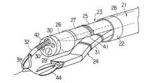
図1中、21は略円筒形状に形成された器具誘導用案内管であり、この器具誘導用案内管21は図示しない内視鏡の挿入部の外周に被嵌してその内視鏡の挿入部をガイドとして体腔内に誘導される。器具誘導用案内管21は可撓性のある長尺な管状部材によって形成されている。器具誘導用案内管21の先端には硬質の補強管22が取着されている。また、器具誘導用案内管21はその補強管22を含めて内外の径が全長にわたり等しく形成されている。
【0022】
上記器具誘導用案内管21の内孔には処置操作の観察を目的として特別に作られた1本の処置専用内視鏡23(以下、処置用内視鏡と呼ぶ)と、2本の処置具用案内管24がそれぞれ独立的に挿入されるようになっている。これら3つの器具は一緒または個別的に器具誘導用案内管21内に進退自在に挿入配置される。また、3つの器具の横断面の外形状(横断面形状とも呼ぶ)はその総和の横断面形状が略円形になり、それらの器具の直線部が、近接(接触する場合を含む)するように密集して配置される充填した関係で組み合わされるように構成されている。そして、上記3つの器具のうち少なくとも一つのものの横断面の外形状が上記器具誘導用案内管21の内孔の寸法よりもわずかに小さい径の弧の部分を持ち上記3つの器具を組み合わせて上記器具誘導用案内管21に入れる際にその組み合わせた全体の横断面の最長寸法が上記器具誘導用案内管21の内孔の径よりわずかに小さい寸法を有する形状になるように構成されている。
【0023】
上記処置用内視鏡23の挿入部25は先端部26と湾曲部27と可撓管部28とからなり、この挿入部25の横断面形状はその略全長にわたり同じく半円形に形成されている。挿入部25の横断面形状における円弧部の半径は上記器具誘導用案内管21の内孔の半径よりも僅かに小さく形成され、上記挿入部25は器具誘導用案内管21の内孔の半円の領域に略密に配置され、前後に進退自在に挿入される。
【0024】
処置用内視鏡23の先端部26には一般的な内視鏡と同様に観察手段と照明手段が組み込まれ(共に図示せず)、先端部26の先端面にはその観察手段の観察レンズ29と、その照明手段の照明レンズ30が配設されている。
【0025】
各処置具用案内管24は全長にわたりその横断面形状が円の1/4の扇形である可撓性のある長尺な管状部材によって形成されており、これらの処置具用案内管24の先端には硬質の補強管24aが取着されている。また、処置具用案内管24はその補強管24aを含めて略全長にわたり内外の径が等しく形成されている。各処置具用案内管24の横断面形状における円弧部の半径は上記器具誘導用案内管21の内孔の半径より僅かに小さい。そして、2つの処置具用案内管24を組み合わせることによりその組み合わせた全体の横断面形状が略半円形になり、上記器具誘導用案内管21の内孔の半円の領域に略密に配置され、かつ上記器具誘導用案内管21内に全体及び個別的に前後に進退自在に挿入される。
【0026】
以上のようにして、上記器具誘導用案内管21の内孔に配置される1本の処置用内視鏡23と2本の処置具用案内管24はその3本のものの総和の横断面形状が略円形になり、それらの接合する内側の直線部が近接して比較的密に組み合わせられて上記器具誘導用案内管21内に全体及び個別的に進退自在に配置されるようになっている。
【0027】
各処置具用案内管24はいずれも左右方向の2方向または上下左右方向の4方向に湾曲させる湾曲機能を有する湾曲部31を備えてなり、その湾曲部31は手元側での操作により強制的に湾曲させられることによって処置具用案内管24の先端部分を上下左右に移動したり処置具用案内管24の先端の向きを変えたりすることができるようになっている。
【0028】
また、処置具用案内管24の湾曲部31は種々の偏倚または変向を得るために複数の湾曲部分を組み合わせて構成しても良い。例えば手元側部分を左右に広がる向きに湾曲し、先端側部分を内側に向ける湾曲を行うようにすると、図1で示すように病変部39を処置する上で都合が良い。
【0029】
各処置具用案内管24には把持鉗子32や高周波スネア切開具36等の治療等に必要な処置具が個別的に挿通されるようになっている。本実施形態では、左側の処置具用案内管24に把持鉗子32を挿入して1つの処置具ユニット(処置装置)35を構成し、右側の処置具用案内管24に高周波スネア切開具36を挿入して別の処置具ユニット(処置装置)37を構成している。
【0030】
尚、上記各処置具ユニットは把持鉗子32や高周波スネア切開具36等の処置具が単独の場合も含むものとする。
【0031】
(作用・効果)
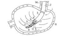
この第1実施形態の内視鏡治療装置を用いて胃38の内壁に生じた病変部39を切除する内視鏡的外科手術を行う場合について説明する。まず、胃38内に比較的太径の図示しない、例えば軟性内視鏡を挿入し、この内視鏡の挿入部に予め外装しておいた器具誘導用案内管21を、その軟性内視鏡の挿入部に沿ってスライドしながらその先端部分が病変部39の近くになるまで誘導する。この後、器具誘導用案内管21の挿入した後の姿勢を維持しながら上記内視鏡のみを抜き取る。
【0032】
次に、平面部分が互いに合うようにして1本の処置用内視鏡23と2本の処置具用案内管24を円柱状に束ね、これらを一緒に器具誘導用案内管21の内孔に挿入する。そして、器具誘導用案内管21の先端開口から処置用内視鏡23と処置具用案内管24の先端部分を突き出すようにする。この後、右側の処置具用案内管24には把持鉗子32を挿通し、左側の処置具用案内管24には高周波スネア切開具36を挿入する。
【0033】
ついで、図1で示すように、右側の処置具用案内管24と左側の処置具用案内管24に挿入した把持鉗子32と高周波スネア切開具36を進退操作し、また、各処置具用案内管24の湾曲機能を利用し、その案内管24の湾曲部31を適宜湾曲操作することにより、把持鉗子32と高周波スネア切開具36の先端の位置決め操作を行う。
【0034】
このような操作を行うことにより病変部39に高周波スネア切開具36のスネアワイヤ36aのループ部分を掛けると共に、把持鉗子32により病変部39を把持して隆起させながら高周波スネア切開具36のスネアワイヤ36aで病変部39の根元部分を絞り込み、そのスネアワイヤ36aに高周波を通電して病変部39を切除する。
【0035】
この際、処置具ユニット35,37から独立した処置用内視鏡23により病変部39の状態と把持鉗子32及び高周波スネア切開具36の位置や動きを観察しながら操作を行うことができるため、処置作業が容易であり、かつ迅速に処置することができる。
【0036】
以上の如く、処置用内視鏡23による観察機能及び湾曲機能と、処置具ユニット35,37による処置機能及び湾曲機能とが独立しているために、処置用内視鏡23の先端部26を病変部39に対して斜め上に位置させることができる。また、病変部39と処置具ユニット35,37の動きや位置等を観察して処置操作の全体像を確実に把握することができる。しかも、器具誘導用案内管21によって各器具の位置が安定的に保持されるので、病変部39の処置作業を確実かつ迅速に行うことができる。
【0037】
勿論、処置具ユニット35,37の位置が自由に選べ、不必要に近接させることがないので、処置用内視鏡23の観察視野を妨げることがない。また、観察しようとする視野が処置具ユニット35,37の影に入ったりすることを極力避け得るので、明瞭な画像で観察することができる。
【0038】
また、処置具ユニット35,37の案内管24の方にも湾曲機能が付いているので、2本の処置具の距離を十分に離して使用することができる。従って、操作性が良いと共に、特に大掛かりな手術となる大きい病変部39や深く浸潤した病変部39であっても容易に対処することが可能である。
【0039】
さらに、左右横方向に処置具を動かせるので、例えば、体壁を横方向に伸ばして、伸びた箇所を電気メスで切開するなどの様々な処置にも適用が可能なものである。
【0040】
[第2実施形態]
図2を参照して本発明の第2実施形態を説明する。
【0041】
(構成)
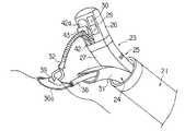
本実施形態では上記器具誘導用案内管21内に挿通される処置用内視鏡23の先端部26の横断面形状が円形であり、一方、挿入部25の湾曲部27及び可撓管部28の横断面形状が上側のみを半円形状にしたものである。挿入部25の湾曲部27及び可撓管部28はその下側半分が切除された形状であり、この切除後の空間部分によって、後述する1本の処置具用案内管24を嵌め込む収納用空間41を形成する。
【0042】
上記処置用内視鏡23の先端部26における先端面には、観察手段の観察レンズ29と照明手段の照明レンズ30の他に挿通用チャンネル(処置具挿通管路)42の先端が開口している。この挿通用チャンネル42は挿入部25の全長にわたり形成されるものである。ここで、観察レンズ29は先端部26の先端面における比較的下側部位に位置して配置され、照明レンズ30はその近くの左右に位置して配置されている。さらに挿通用チャンネル42の先端開口は比較的上側に位置する部位に配置されている。つまり、挿通用チャンネル42の先端開口は観察レンズ29及び収納用空間41よりも上側に位置して配置されている。
【0043】
上記処置具用案内管24は全長にわたりその断面形状が半円扇形の断面形状を有した可撓性のある長尺な管状部材によって形成されており、上記処置用内視鏡23の収納用空間41内に適合して嵌め込まれる形状に構成されている。つまり収納用空間41内に処置具用案内管24を抱き込むように嵌め込んで収納したときの総和の横断面形状が略円形になり、両器具の直線部が接する状態で密に配置される関係で両器具が組み合わされ、上記器具誘導用案内管21内に纏めて一緒に挿通可能なように構成されている。
【0044】
しかして、処置具用案内管24の横断面形状は半円形であり、この半円形と、処置用内視鏡23の湾曲部27及び可撓管部28の部分の横断面形状の半円形とを合わせた横断面形状が略円形となり、この総和の円形の外径が上記器具誘導用案内管21の内径よりも小さくなるように、各器具は円弧と直線を組み合わせた横断面形状にて構成されている。
【0045】
また、処置具用案内管24は前述した第1実施形態と同様に湾曲機能を有する湾曲部31を有しており、その湾曲部31は手元側での操作により強制的に湾曲させられるようになっている。
【0046】
(作用)
本実施形態では1本の処置用内視鏡23の収納用空間41に処置具用案内管24が抱き込むようにした形に組み合わせられ、そして、両器具を器具誘導用案内管21内にまとめて挿入するようにしたものである。
【0047】
そこで、第1実施形態で述べたと同様に器具誘導用案内管21を体腔内に導入し、器具誘導用案内管21の先端から処置用内視鏡23及び処置具用案内管24の先端部分を突き出し、さらに処置具用案内管24を下側に湾曲して収納用空間41から離脱させて前方へ進める。
【0048】
そして、図2で示すように、処置用内視鏡23の挿通用チャンネル42を通じて把持鉗子32を挿通し、処置具用案内管24には鋏鉗子44を挿通して、病変部39を切除する手技を行う。
【0049】
また、処置用内視鏡23の挿通用チャンネル42を通じて把持鉗子32を挿通すると共に、第1実施形態で述べた如く、処置具用案内管24に高周波スネア切開具36を挿通して病変部39の高周波切除を行うこともできる。
【0050】
(効果)
本実施形態では処置具用案内管24に処置用内視鏡23と処置具用案内管24を後入れする際、それらの先端部が分かれていないので、複数の器具を挿入するにも拘らず、複数の器具がバラバラになり難く、また、引っ掛かりや挿入抵抗が少なく、複数の器具を器具誘導用案内管21に挿入しやすい。
【0051】
処置具用案内管24としては1本のみ用いるので、その占有空間を大きくすることが可能であり、案内管24の内部空間を第1実施形態のものに比べ大きくすることができる。従って、大きい処置具を挿入して使用することができる。
【0052】
また、第1実施形態の場合では主に横方向から処置操作を行うようにしたが、本実施形態では縦方向から処置操作ができるので、腫瘍のできた粘膜を把持鉗子32で引っ張り上げて大きく隆起させてから鋏鉗子44で剥離するなどの手技が容易である。
【0053】
さらに、処置用内視鏡23の先端部26を大きくすることができるため、大きな観察光学系及び照明光学系を組み込むことができ、それらの能力を高めることが容易である。
【0054】
[第3実施形態]
図3を参照して本発明の第3実施形態を説明する。
【0055】
(構成)
本実施形態では上記器具誘導用案内管21内に挿通される処置用内視鏡23の挿入部25が先端部26を含めてその横断面形状が上側のみの半円形である。また、湾曲機能付きの処置具用案内管24の横断面形状は前述した第2実施形態と同様に下側のみの半円形であり、その挿入部25と処置具用案内管24の直線部分が互いに接合されたときの総和の横断面形状が略円形になり、両器具の平面部分が接合した組み合わせの状態で、上記処置具用案内管24内に挿通可能なように構成されている。
【0056】
上記処置用内視鏡23の挿入部25における先端部26の下側面部(処置具用案内管24との境界面側に向く部分)には観察手段の観察レンズ29と照明手段の照明レンズ30が前後に並べて配設してなり、この処置用内視鏡23は側方視観察と側方視照明を行う側視型形式のものとなっている。
【0057】
上記観察レンズ29の内側には図示しない固体撮像素子などの撮像手段が設けられ、また照明レンズ30の内側には図示しないライトガイドファイバの先端が配置されている。上記ライトガイドファイバはその手元側遠位端から同じく図示しない光源装置からの光を受け、その光を側方へ向けた照明レンズ30に伝達して体腔内を照明するようになっている。
【0058】
また、処置用内視鏡23の挿入部25における先端部26の下面部には挿通用チャンネル42の出口42aが形成され、この出口42aには処置具を曲げる処置具起上台43が具備されている。処置具起上台43は先端部26に所定の角度の範囲内で回転自在に枢着されている。そして、通常、処置具起上台43は倒伏して出口42a内に収納された姿勢にあるが、処置用内視鏡23の図示しない操作部に設けた起上操作レバーを回転させると、これに連動する起上ワイヤー(図示せず)の牽引により起上するようになっている。
その他の構成については、前述した第1実施形態または第2実施形態のものと同様の構成である。
【0059】
(作用)
これまでの例と同様に、予め、図示しない内視鏡を用いて、病変部39の近くに先端がくるように器具誘導用案内管21を体腔内に挿入して留置する。処置用内視鏡23の挿入部25と処置具用案内管24を抱き合わせると共に、処置用内視鏡23の観察レンズ29よりも先端が後方に位置するように処置具用器具誘導用案内管21をずらす。この状態のまま、処置用内視鏡23により器具誘導用案内管21の内壁を観察しながら処置用内視鏡23の挿入部25と処置具用案内管24の両方を一緒に器具誘導用案内管21内に挿入していく。
【0060】
処置用内視鏡23の挿入部25の先端部26が器具誘導用案内管21の先端から突き出し、処置用内視鏡23により体腔壁が見え、その先端部26が器具誘導用案内管21の先端から突き出したことを確認したら、処置用内視鏡23の湾曲部27を湾曲させつつ、その挿入部25を適宜回転させて、病変部39を真上から観察するようにする。このとき、処置具用案内管24も挿入部25と一緒に回転させる。
【0061】
次に、処置具用案内管24に高周波スネア切開具36を挿通し、その処置具案内管24を湾曲させたり進退させたりし、さらには高周波スネア切開具36を適宜進退させながら、病変部39に高周波スネア切開具36のループワイヤ36aを掛ける。続いて、処置具、例えば把持鉗子32を処置用内視鏡23の挿通用チャンネル42に挿通し、その出口42aから体腔内に先端部を突き出す。さらに起上台43を適宜起上して把持鉗子32のシース先端部分を側方へ曲げるように押しながら把持鉗子32により、病変部39を掴み、病変部39を引っ張り上げる。この後、高周波スネア切開具36のループワイヤ36aを引き締めて、通電し、病変部39を切除する。
【0062】
(効果)
ここでの処置用内視鏡23は側方を観察する側視型のものを用いているため、病変部39を真上から観察することが可能であり、高周波スネア切開具36のループワイヤ36aが病変部39の周囲に来ることが容易に分かる。また、病変部39を掴む操作も、病変部39を引っ張り上げる操作も、ループワイヤ36aを締める操作のいずれも観察しながら確実に行うことができ、処置の確実性を向上することが出来る。さらに2本の処置具を独立して操作することができるので、失敗によるやり直しが少ない。
【0063】
尚、本実施形態では処置用内視鏡23の観察方向がその内視鏡23の長手方向の軸に対して90度の角度にしたが、病変部39の部位によっては後方斜視にしたり、前方斜視にしても良い。組み合わせて使用する処置具の種類も、クリップと電気メス、T字形状のタグで引き上げてレーザ−プローブでカットするとか色々のものが考えられる。また、上述した第1実施形態の場合のように、2本の処置具用案内管24を使用するようにしても良い。
【0064】
[第4実施形態]
図4を参照して本発明の第4実施形態を説明する。
(構成)
本実施形態では処置具用案内管24の代わりに先端が斜めにカットされた透明で柔軟なウレタン樹脂製のキャップ50を先端に設けた湾曲機能付きの吸引チューブ51を用いるようにした処置具ユニットの例である。また、処置用内視鏡23はその先端部26の所の横断面の外形状が略円形な外形であり、湾曲部27と可撓管部の所には横断面の外形状が三日月形状の収納用凹溝部52を形成した。上記吸引チューブ51はその収納用凹溝部52内に嵌め込まれて収納されるようになっている。
【0065】
処置用内視鏡23の先端部26においての上記収納用凹溝部52を配置する側に位置する下面部には観察手段の観察レンズ29と照明手段の照明レンズ30が前後方向に並べて配設され、これにより前述した第3実施形態の場合と同様、側方視観察と側方視照明を行う側視型の内視鏡を構成している。
【0066】
先端部26の下面部には、挿通用チャンネル42の出口42aが形成されており、この出口42aには前述した第3実施形態の場合と同様、処置具の突き出し方向を調節する処置具起上台43が備えられている。上記先端部26にはさらに洗浄水や空気を吹き付けて観察レンズ29の外表面を洗浄する洗浄ノズル53が配設されている。また、この実施形態での照明手段の光源は先端部26に内蔵される白色LEDである。
【0067】
(作用)
まず、前述したように、図示しない内視鏡挿入部を用いて、病変部39の近くに先端がくるように器具誘導用案内管21を体腔内に挿入して留置する。次に、処置用内視鏡23の収納用凹溝部52内に吸引チューブ51を嵌め込むことにより両者を抱き合わせて両方の器具を一緒に纏め、このように組み合わされた処置用内視鏡23と吸引チューブ51の両者を器具誘導用案内管21内に挿通し、その先端部分が体腔内の病変部39の近傍に位置する場所まで導く。
【0068】
そして、病変部39の近傍に導いたところで、処置用内視鏡23の湾曲部27を吸引チューブ51から離れる向きに湾曲し、その処置用内視鏡23から吸引チューブ51を分離する。例えば静脈瘤のような病変部39の場合、病変部39を視野内に捉えたら病変部39の周囲に挿通用チャンネル42を通じて挿入したループ留置具54のループワイヤ55を押し付けて位置決めさせる。この後、病変部39に吸引キャップ50の先端部分を被せる。
【0069】
そして、吸引ポンプのスイッチをオンとし、吸引キャップ50内に病変部39を吸い込む。吸引キャップ50内に病変部39が十分に吸い込まれたところで、その病変部39の周囲に配置した上記ループワイヤ55を絞り込み、その後、ループワイヤ55の部分を切り離し、病変部39を把束した状態で、ループワイヤ55を放出してそのまま留置する。
【0070】
(効果)
本実施形態によれば、把持鉗子やクリップで病変部39を引き上げる場合に比べて、大きな病変部39を十分に引き上げることができる。また、吸引キャップ50内に病変部39を吸引する力を十分に強くすることができるので、病変部39の引き締め時、または病変部39を引き上げる時、処置具の方が病変部39側に引き込まれてしまう不具合がない。加えて、吸引力をコントロールすることにより、広範な病変部39や深い病変部39であっても的確な処置が可能になる。
【0071】
本実施形態では処置用内視鏡23の湾曲部27の部分から手元側にわたりその横断面形状が三日月形状の収納用凹溝部52を形成しているが、湾曲部27も先端部26と同様、横断面形状が円形なものとしてその湾曲部27の後端に続く可撓管部28の部分から収納用凹溝部52を形成するようにしても良い。
【0072】
また、上記吸引チューブ51の横断面形状も円形のものに限るものではなく、半円、扇状、三日月状などの形状として、相手の処置用内視鏡23の横断面形状と組み合わせたときに略円形になるようにしてもかまわない。
【0073】
さらには処置用内視鏡23の先端部26の横断面形状も円形のものに限るものではなく、前述した図3で示した第3実施形態のもののように半円形状にしたものでも良い。
【0074】
また、ループ留置具54の代わりに前述したような高周波スネア切開具36を用いて病変部39を焼灼して切除するようにしても良い。
粘膜下の腫瘍や陥凹型の病変部について処置する場合には、予め、処置用内視鏡23を用いて注射器を挿入し、病変部39の下に生理食塩水を注入し、筋層から病変部39を剥離し、病変部39を隆起させておくようにしても良い。また、病変部39が判別し難い揚合は目印をつけておいて病変部39を処置するようにしても良い。
【0075】
[第5実施形態]
図5を参照して本発明の第5実施形態を説明する。
【0076】
(構成)
本実施形態では、体腔内の病変部39を引き上げる手段として、上述した第4実施形態の吸引チューブ51の代わりに2番目の処置用内視鏡60を用い、これを一つの処置具ユニットとして上述した第4実施形態の処置用内視鏡23に組み合わせるようにしたものである。
【0077】
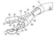
この2番目の処置用内視鏡60は先端部61と湾曲部62を有する挿入部63を備えてなり、その先端部61の先端面には観察手段の観察レンズ64と照明手段の照明レンズ65とを設け、その観察レンズ64の後ろの部分には観察手段としてイメージガイドファイバを設け、照明レンズ65の後ろの部分には照明手段としてライトガイドファイバを設ける。上記先端部61の先端面には挿通用チャンネル66の先端を開口し、これにより処置具を突き出すようになっている。つまり、この2番目の処置用内視鏡60も第2実施形態での処置用内視鏡23と同様の直視型内視鏡を構成している。
【0078】
(作用)
処置用内視鏡23で真上から体腔内の病変部39を観察しつつ、2番目の処置用内視鏡60で、病変部39を横方向から観察しつつ、両方の処置用内視鏡23,60を用いて各種の処置を行うことができる。
【0079】
例えば、処置用内視鏡23の挿通用チャンネル42を通じて導入したループ留置具54のループワイヤ55を病変部39のまわりにおき、2番目の処置用内視鏡60の挿通用チャンネル66を通じて挿入したT字形のタグ67を病変部39の壁に貫通させてその病変部39を引き上げ、上記ループ留置具54のループワイヤ55にて病変部39を結紮し、この後、ループワイヤ55を放出してループ留置具54を留置する。
【0080】
(効果)
以上の如く、2つの処置用内視鏡23,60により病変部39を観察しつつ引き上げ具としての第2の処置用内視鏡60を使用するので処置がし易い。
【0081】
もちろん、処置方法は反対の組み合わせ、つまり、処置用内視鏡23側で引き上げ、2番目の処置用内視鏡60側で結紮して留置するようにしても良い。また、処置部位によっては処置用内視鏡23の観察方向は側方でなくて直視でも良いし、また、2番目の処置用内視鏡60には照明手段を設けなくても内視鏡23の照明手段でカバーできる症例もある。2番目の処置用内視鏡60は観察手段に固体撮像素子を用いた電子内視鏡としても良い。これらの横断面形状も上記の形状に限るものではない。
【0082】
[第6実施形態]
図6を参照して本発明の第6実施形態を説明する。
【0083】
(構成)
本実施形態では処置用内視鏡23の挿入部25の横断面形状が略半円形であり、その先端部26における先端面が45度の斜めにカットされており、この処置用内視鏡23はその観察方向が前方に45度の斜めになっている斜視型のものとなっている。先端部26の斜めの先端面には2つの照明レンズ30と、1つの観察レンズ29と、1つの処置具挿通用チャンネル(処置具挿通管路)42の出口が設けられている。照明レンズ30にはライトガイドファイバー束からなる照明光伝達手段がそれぞれ接続されている。また、挿通用チャンネル42の先端の出口の内部には処置具起上台43が配設されている。
【0084】
また、本実施形態では上記処置用内視鏡23と対を成す湾曲機能付きの自動縫合器70が設けられ、この自動縫合器70の挿入部71は上記処置用内視鏡23の挿入部25の略半円形の横断面形状と対を成す略半円形の横断面形状を持ち、上記器具誘導用案内管21内にまとめて挿入されるようになっている。つまり、処置用内視鏡23の挿入部25と自動縫合器70の挿入部71を組み合わせたときの総和の横断面形状は略円形になり、それらの接合する内側の直線部が近接して比較的密に組み合わせられて上記器具誘導用案内管21内に進退自在に配置され得るようになっている。しかして、処置用内視鏡23の挿入部25と自動縫合器70の挿入部71を組み合わせたときの総和の円形な横断面形状の外径は上記器具誘導用案内管21の内孔の内径よりも僅かに小さく形成されている。
【0085】
上記自動縫合器70の挿入部71における先端部には開閉自在な一対のジョー72を有した縫合部73が設けられている。一対のジョー72はその内側に縫合用ステープル74を装着し、一対のジョー72を閉じて組織部分を挟み込むことにより組織部分をステープル74で縫合するようになっている。また、一対のジョー72は閉じておくことにより処置用内視鏡23の挿入部25と一緒に上記器具誘導用案内管21内に進退自在に挿入配置することができる。
【0086】
(作用)
処置用内視鏡23により斜め上から体腔内を観察するとき、その視野内に病変部39を捉えたら挿通用チャンネル42を通じて把持鉗子32を挿入し、この把持鉗子32で病変部39を掴む。この際、必要に応じて処置具起上台43を上げ下げ回動して、把持鉗子32による把持位置を調整する。把持鉗子32で病変部39を掴んだらその把持鉗子32を処置用内視鏡23の先端部26近くまで引き込み、その状態で処置用内視鏡23の湾曲部27を湾曲させることにより病変部39を持ち上げる。
【0087】
この際、自動縫合器71の縫合部73の一対のジョー72を開いてその間の位置に病変部39の根元部分を位置させる。この後、一対のジョー72の間で病変部39を挟み込み、ステープル74により縫合する。
【0088】
(効果)
本実施形態では、斜め上から病変部39の全体像を捉えることができるので、病変部39の根元部分を縫合する処置の操作がしやすい。また、前述したような処置具用案内管24を介さず、直接に器具誘導用案内管21内に自動縫合器70を挿入するようにしたので、比較的大型の自動縫合器70を使用することができる。さらに、自動縫合器70は異形な大型の横断面形状に形成した湾曲機能付きの処置具であるのが普通であるが、器具誘導用案内管21内に直接挿入するようにしたので、余裕をもって使用することができる。その結果、処置範囲を拡大することができる。
【0089】
尚、処置用内視鏡23の挿入部25における先端面が45度の斜めにカットしたが、そのカットする角度は45度に限るものではない。また、自動縫合器70の代わりに超音波振動切開具、高周波切開ハサミ鉗子、前述した高周波ワイヤ切開具または後述する図10に示すような高周波切開具などを用いれば、より広範囲な粘膜の切除が容易である。さらに、縫合器の縫合方向は軸に平行な上記の例に限るものではなく、直角な方向であっても良い。
【0090】
[第7実施形態]
図7を参照して本発明の第7実施形態を説明する。
【0091】
(構成)
本実施形態の処置用内視鏡23はその先端部26のみが比較的径の大きな円形の横断面形状を有するものである。先端部26の側方部位には観察光学系の観察レンズ29と照明光学系の照明レンズ30が設けられており、この観察レンズ29と照明レンズ30とは円筒形のアクリル樹脂製の透明カバー75によって覆われている。
【0092】
処置用内視鏡23の先端部26には湾曲部27及び可撓管部28を有してなる細管76が接続されている。この細管76は先端部26の径よりも小さい径を有し、その先端は先端部26の中心軸から外れ、先端部26の上周面に一杯の上側にずれて位置し、先端部26の後端に接続されている。
【0093】
また、処置用内視鏡23の先端部26の後端から細管76を避けた領域には上記同様に湾曲機能を有する処置具用案内管80が配置されるようになっている。処置具用案内管80の上側周面部分には上記細管76を嵌め込み配置するための凹溝部81を処置具用案内管80の長手方向に沿って長く形成してなり、その凹溝部81を含む部分の横断面形状の外形状は、いわゆるそら豆みたいな形になっている。
【0094】
上記凹溝部81内に細管76を配置するようにして処置用内視鏡23と処置具用案内管80を密に組み合わせたときの総和の横断面形状は略円形になり、両者は上記処置用案内管80内に進退自在に配置される。
上記処置具用案内管80内には同じくそら豆形状の横断面形状を有する2本の処置具挿通用チャンネル82が貫通して設けられている。
【0095】
(作用)
処置用内視鏡23の先端部26の後端から細管76を避けた領域に上記処置具用案内管80を抱き合わせるようにして両者を組み合わせる。そして、両者を器具誘導用案内管21内に挿入して体腔内まで導き入れる。両者の先端が器具誘導用案内管21の先端から体腔内に突き出したところで、処置具用案内管80の湾曲部83に湾曲をかけて処置用内視鏡23から分離する。
【0096】
そして、図7で示すように処置用内視鏡23によって病変部39を真上から観察しながら処置具用案内管80の2本の処置具挿通用チャンネル82を通じてそれぞれ挿入した対の処置具で病変部39を処置する。例えば、把持鉗子32で病変部39を摘まんで引っ張り上げながら高周波スネア切開具36によって病変部39を切除する。
【0097】
(効果)
処置用内視鏡23の先端部26の横断面形状が太い径の円形なものであり、湾曲部27及び可撓管部28を有する細管76はそれよりも細い径の円形のものであるため、先端部26に観察光学系と照明光学系の主要部を組み込み、細管76には他の部材を組み込むことにより、特に細管76の構造を簡単にすることができる。また、細管76の部分の横断面形状が円形なので、その細管76を湾曲する際に偏るなどの乱れた動きを招かない。
【0098】
尚、本実施形態での処置具用案内管80は一本のみを用いる場合として説明したが、2本の処置具用案内管80を用いて処置用内視鏡23の先端部26の後ろに配置するようにしても良い。この場合、各処置具用案内管80には1本の処置具挿通用チャンネル82を形成するようにしても良い。また、使用する各処置具の組み合わせもこの例に限るものではなく、例えば、上述したような各種の組み合わせが考えられる。
【0099】
[第8実施形態]
図8を参照して本発明の第8実施形態を説明する。
【0100】
(構成)
本実施形態では前述した第1実施形態のものと類似するものであるが、その処置機能のある器具が、湾曲機能付きの把持鉗子85と、湾曲機能付きの処置具用案内管86に挿通される処置具、例えば高周波処置具87としたものである。上記把持鉗子85のシース88の部分における横断面形状は中心近くの角が鋭角な扇型であり、上記処置具用案内管86の横断面形状は中心近くの角の角度が鈍角な扇型であり、以上の2つの角度を合わせると180度になり、両者を合わせた総和の横断面形状が略半円になるようになっている。
【0101】
一方、処置用内視鏡23の横断面形状は略半円であり、この半円と上記処置機能側の半円の両者を合わせると、略円形になり、その円形の外径は上記処置機能部材を挿通する器具誘導用案内管21の内径よりも僅かに小さくなるように形成してある。つまり、把持鉗子85と、処置具用案内管86と、処置用内視鏡23の3者を接合して纏めると、器具誘導用案内管21の内孔内に挿通できるように組立てられるように構成されている。
【0102】
(作用)
第1実施形態とは異なり、処置操作はシース88の横断面形状が異形の処置具と、処置具用案内管86に挿通した処置具の組み合わせにより処置する。
【0103】
(効果)
本実施形態によれば、処置具用案内管を利用して処置具を用いる場合に比べ、大きい処置具を用いて処置することができる。従って、大きいポリープ等の処置を容易に行うことが可能になる。
【0104】
尚、処置機能を有する側の各部材の抱き合わせたときの総和の横断面形状、及びこれらを挿通する器具誘導用案内管21の横断面形状を真円ではなく、楕円などの非円形(異形)に形成しても良い。
【0105】
[第9実施形態]
図9を参照して本発明の第9実施形態を説明する。
【0106】
(構成)
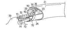
本実施形態がこれまでの各実施形態のものと異なる点は器具誘導用案内管21の壁部の一部に簡易式の照明手段を組み込むようにしたところにある。この照明手段の照明レンズ90はその器具誘導用案内管21の先端面に設けられている。また、照明手段のライトガイドファイバーと小型のハロゲンランプと電池とからなるバッテリーは器具誘導用案内管21の壁部内に内蔵されている。また、処置用内視鏡23と湾曲機能付きの処置具用案内管24の横断面形状はそれぞれ半円である。
【0107】
(作用・効果)
このように構成したので、内視鏡の挿入部に沿って体腔内の病変部39近くまで先端を導入された器具誘導用案内管21の照明手段を点灯して病変部39を照明することができる。また、処置用内視鏡23と湾曲機能付きの処置具用案内管24を抱き合わせて器具誘導用案内管21内に挿入し、その処置用内視鏡23に設けられた挿通用チャンネル42を通して挿入した把持鉗子32で、病変部39を含む体腔壁を引っ張り上げて自動縫合器70で縫合する。また、処置用内視鏡23と処置具用案内管24を通じて種々の処置具を挿入し、種々の処置を行うことができる。
【0108】
また、器具誘導用案内管21に照明手段を組み込んだので、処置用内視鏡23の照明手段のライトガイドの本数を削減することが可能になり、処置用内視鏡23の外径を細くすることができる、これにより、間接的且つ相対的に同時に用いる処置具用案内管24自体を太くすることが可能になり、大型の処置具、自動縫合器や超音波振動熱焼灼カッタとかを用いることができるようになる。
【0109】
本実施形態では器具誘導用案内管21の壁の全てにライトガイドを埋め込むとか、白色のLEDを先端に内蔵するとかして照明手段を構成するようにしても良い。この照明手段の照明光量を上げれば、処置用内視鏡23は観察手段だけでもよく、これによって処置用内視鏡23や処置具用案内管24の更なる細径化やその処置具挿通用チャンネルの径を太くすることができる。
【0110】
[第10実施形態]
図10を参照して本発明の第10実施形態を説明する。
【0111】
(構成)
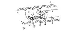
本実施形態では器具誘導用案内管21に挿入して使用される処置用内視鏡23の先端部26の形状が、砲弾型形状のものの先端途中から後方部分を斜め45度の角度に切り取って除き、その開いた部分に砲弾型形状の外径より小さい外径を有する円筒状部91を中心を片側に寄せ付けた形に形成したものである。先端部26の最大外径は器具誘導用案内管21の内径より僅かに小さく、上記円筒状部91はその最大外径の外形領域内に入り込むように構成されている。2つの外径の差の部分に形成される三日月状の段差面92には観察手段の観察レンズ29と照明手段の照明レンズ30とが後方斜めに向けて配設されている。
【0112】
この段差に対向する窪み位置にはその段差の三日月形状に近い断面形状のシース93を有する湾曲機能付きの高周波レゼクト処置具94が配置されるようになっている。高周波レゼクト処置具94はシース93の先端に円弧状の高周波ワイヤ95を進退自在に設けられている。また、先端部26は合成樹脂などの絶縁材料で作られている。
【0113】
(作用)
処置用内視鏡23に高周波レゼクト処置具94を抱き合わせてこれらを一緒に上記器具誘導用案内管21内に挿入して使用される。例えば、図示しない内視鏡を利用して食道96に器具誘導用案内管21を挿入し、続いて処置用内視鏡23と高周波レゼクト処置具94を抱き合わせてこれらを一緒に上記器具誘導用案内管21内に挿入し、体腔内に突き出して病変部39を確認する。病変部39を確認したら処置用内視鏡23で後方を観察しながら食道96と胃97の境界の噴門部98に生じた病変部39(例えばバレット上皮や腫瘍)に対して円弧状の高周波ワイヤ95に通電しながら当てて引き上げることで、病変部39の組織を削ぎ落とす。
【0114】
(効果)
もともと、噴門部98の所は狭まっているために観察が難しく、病変部39を見落としがちであった。また、逆流性食道炎やバレット上皮という、噴門部98の内面の粘膜の病気が増えているが、その観察/処置が難かった。従来、内視鏡先端を胃97内に挿入し、内視鏡先端に湾曲を180度以上かけた状態で噴門部98の胃97側から見上げる状態で観察していたが、この方法では胃97側しか見えないし、処置をするにも内視鏡挿入部が邪魔になる。湾曲を180度以上にすると、先端部26がふらつくため、処置具が狙い通りに病変部39を捉えられないなどの欠点があった。
【0115】
また、食道96側から観察方向が前方の、いわゆる直視型内視鏡で、観察/処置をしようとすると、噴門部98が閉じているので、押し広げながらの観察になる。内壁と先端が密着しているので、俗に言うところの赤玉状態になり、狭い範囲の観察しかできない。噴門部98の近くにおいても、内壁は横からの観察と処置になるので病変部39を確実に捉えることができず、処置がやりにくかった。また、斜視型や側視型の内視鏡では観察は容易になるのであるが、内視鏡の処置具挿通用チャンネルの出口に設けた鉗子起上台を操作して、処置具を観察方向に曲げることになり、処置具の動きは内壁に沿って病変部39を削ぎ取るような動きにはならなかった。また、処置具挿通用チャンネルを通じて挿入することができる処置具は細く腰がないため、内壁を十分に捉えることは難しかった。
【0116】
しかし、本実施形態では、観察方向をこれまでにない後方斜視にし、処置用内視鏡23の先端部26と上記器具誘導用案内管21を用いて噴門部98を押し広げることによって、これまで、観察や処置が難かった噴門部98の胃97側から食道96側を一度に観察と処置ができる。また、処置具と処置用内視鏡23を同時に引きながら徐々に処置することで、病変部39を近くで観察しながら確実に処置することができるようになった。
【0117】
また、処置具と処置用内視鏡23が独立しているので、処置用内視鏡23の先端は固定して、病変部39を定点観察しつつ、処置具を曲げて食道96の内壁に沿うように引き動かすことができる。
【0118】
バレット上皮の場合、治療は全周を削ぎ落とすことになるが、内視鏡の処置具挿通用チャンネルを通しての処置具であると、シースが細いので腰が弱く、先端が大きくできないので、処置する面積が少なくなり、全周を処置するには何回も繰り返して、処置をする必要があり、面倒であった。
しかし、本実施形態では処置具、特に高周波ワイヤ95の部分を長くできるので、全周を処置する回数が少なくできる。
【0119】
この他に、同様に狭まっている幽門部の観察/処置も可能である。十二指腸の狭窄部なども考えられる。
【0120】
尚、本実施形態の段差面92の部分のカットの角度を変えるか、光学系を変えることによって、後方斜視の角度を30度や60度などしても良い。また、器具誘導用案内管21の先端を斜めにカットし、短い側を処置操作に用いるようにしても良い。さらに、使用する処置具としては上述したものの他に、アルゴンプラズマレーザーや、ローラーによる高周波焼灼具等であっても良い。
【0121】
さらには器具誘導用案内管21に挿入する処置用内視鏡は固体撮像素子が大きく、観察能力に優れた内視鏡が適しているので、固体撮像素子を内蔵する先端部分については大きな円形の横断面形状とし、これに比べて湾曲部や挿入部は非円形の小さな横断面形状のものとしても良い。
【0122】
また、前述した実施形態では上記器具誘導用案内管の内孔及びこれに入れる器具の組み合わせた全体の横断面形状が略円形であったが、本発明ではそれに限らず、楕円や長円または他の形状のものであっても良い。
【0123】
処置用内視鏡と処置ユニットの個別の進退をより円滑にするために、それぞれを滑り性に優れる材料を用いるとか、外表面に滑り性の良いコートをするようにしてもよい。また、処置用内視鏡と処置ユニット器具を挿入する案内管の内面に同様のコートを施しても良い。
【0124】
<付記>
1.体腔内に挿入される器具誘導用案内管と、
上記器具誘導用案内管の内孔に進退自在に挿入される少なくとも一つの処置用内視鏡と、
上記器具誘導用案内管の内孔に進退自在に挿入される少なくとも一つの処置具ユニットとを具備してなり、
上記内視鏡と上記処置具ユニットのうち少なくとも一つのものの横断面の外形状が上記器具誘導用案内管の内孔の径よりもわずかに小さい径の弧の部分を持ち、上記内視鏡と上記処置具ユニットを組み合わせて上記器具誘導用案内管に入れる際にその組み合わせた全体の横断面の外形状が上記器具誘導用案内管の内孔の径よりわずかに小さい径を有する形状になるように構成したことを特徴とする内視鏡治療装置。
【0125】
2.体腔内に上記器具誘導用案内管を誘導するための第2の内視鏡を備えた第1項に記載の内視鏡治療装置。
3.内視鏡と処置具ユニットの少なくとも一方における一部の横断面形状を、一部に円弧を有する非円形の形状にすると共に、この円弧の径を器具誘導用案内管の内孔の半径より僅かに小さくし、かつその円弧の部分を外側になるようにして上記内視鏡と処置具ユニットを組み合わせたときの全体の横断面形状が略円形になることを特徴とする内視鏡治療装置。
【0126】
4.内視鏡と処置具ユニットの少なくとも一方における一部の横断面形状の非円形の形状は円弧と別の曲線との組み合わせた形であることを特徴とする第3項に記載の内視鏡治療装置。
5.非円形の形状が、円弧と直線との組み合わせた略扇形状であることを特徴とする第3項に記載の内視鏡治療装置。
【0127】
6.内視鏡と処置具ユニットの断面形状が共に略半円であり、内視鏡と処置具ユニットを組み合わせたときの全体の断面形状が共に略円であることを特徴とする第1項に記載の内視鏡治療装置。
7.内視鏡と処置具ユニットの断面形状が共に略扇形であることを特徴とする第1項に記載の内視鏡治療装置。
8.処置具ユニットは湾曲機能を具備してなることを特徴とする第1項に記載の内視鏡治療装置。
【0128】
9.処置具ユニットは湾曲機能を具備してなる処置具用案内管を有するものであることを特徴とする第1項に記載の内視鏡治療装置。
10.処置具ユニットが少なくとも2本以上のものからなることを特徴とする第1項に記載の内視鏡治療装置。
11.処置具用案内管の少なくとも一部に湾曲機能を設けたことを特徴とする第1項に記載の内視鏡治療装置。
【0129】
12.少なくとも処置具ユニットの一本が処置具であり、もう一本が処置具挿通案内管であることを特徴とする第1項に記載の内視鏡治療装置。
13.内視鏡が処置具挿通管路を具備することを特徴とする第1項に記載の内視鏡治療装置。
14.処置具用案内管は少なくとも一つ以上の処置具挿通管路を有することを特徴とする第1項に記載の内視鏡治療装置。
【0130】
15.器具誘導用案内管は照明手段を有することを特徴とする第1項に記載の内視鏡治療装置。
16.器具誘導用案内管の内面、その器具誘導用案内管に挿入する部分の処置具ユニットの外面、器具誘導用案内管に挿通する第2の内視鏡の外面に潤滑処理を施したことを特徴とする第1項に記載の内視鏡治療装置。
17.器具誘導用案内管の先端と、器具誘導用案内管に挿通される内視鏡の先端が斜めに切断された形状に形成されていることを特徴とする第1項に記載の内視鏡治療装置。
【0131】
18.器具誘導用案内管に挿通される内視鏡の観察方向が側視であることを特徴とする第1,2項に記載の内視鏡治療装置。
19.器具誘導用案内管に挿通される内視鏡の観察方向は後方斜視であることを特徴とする第2項に記載の内視鏡治療装置。
20.器具誘導用案内管に挿通される内視鏡の観察方向は前方斜視であることを特徴とする第2項に記載の内視鏡治療装置。
21.器具誘導用案内管に挿通される内視鏡は処置具挿通用チャンネルを具備し、その内視鏡の先端部の処置具挿通用チャンネルの先端開口部に処置具の起上手段を有することを特徴とする第2項に記載の内視鏡治療装置。
【0132】
【発明の効果】
以上説明したように本発明によれば、体腔内の病変部近くまで導き入れた器具誘導用案内管内に少なくとも一つの内視鏡と少なくとも一つの処置具ユニットを抱き合わせて後入れして用いることができるので、従来の場合よりも処置がし易くなる。すなわち、処置用内視鏡と処置具ユニットを独立させて、別個に操作可能とすることで、広範な病変部を遠目から観察しつつ、必要ならば大型の処置具でもって処置することが可能である。大型の処置具を用いることにより大きな病変を一括して切除できるし、広域な病変部や深く浸潤した病変部の切除を少ない回数で短時間で実施できるなどの利点がある。部分切除でないと、切断面が少ない標本が得られ、切除標本の病理検査がやり易い。その上に、出血が少なく、ガンなどの腫瘍の場合、拡散転移を防ぐことができる。
【0133】
また、器具誘導用案内管とこれに挿通する処置用内視鏡と各種の処置具ユニットを様々な形態で組み合わせて構成することにより、体腔内で、従来よりも、広範な病変部の処置状況の全体を観察しながら適切な手術を容易かつ迅速に行うことができるようになる。
【0134】
さらに、本発明では少なくともどちらかの器具の横断面形状を円形以外のものにして複数の器具を組み合わせるので、双方の器具を極力細くしないように構成することができる。
【0135】
また、器具誘導用案内管の端部を病変部近くに保持するようにすれば、これまで、直視の内視鏡では側方からのアプローチしか出来なかった部位についても、例えば、後入れの内視鏡の観察方向を側視にするなどにより、病変部の上からのアプローチができるようになり処置がし易くなる。
【図面の簡単な説明】
【図1】第1実施形態に係る内視鏡治療装置の使用状態を示す斜視図。
【図2】第2実施形態に係る内視鏡治療装置の使用状態を示す斜視図。
【図3】第3実施形態に係る内視鏡治療装置の使用状態を示す斜視図。
【図4】第4実施形態に係る内視鏡治療装置の使用状態を示す斜視図。
【図5】第5実施形態に係る内視鏡治療装置の使用状態を示す斜視図。
【図6】第6実施形態に係る内視鏡治療装置の使用状態を示す斜視図。
【図7】第7実施形態に係る内視鏡治療装置の使用状態を示す斜視図。
【図8】第8実施形態に係る内視鏡治療装置の使用状態を示す斜視図。
【図9】第9実施形態に係る内視鏡治療装置の使用状態を示す斜視図。
【図10】第10実施形態に係る内視鏡治療装置の使用状態を示す斜視図。
【図11】従来の内視鏡治療装置の使用状態を示す斜視図。
【図12】従来の内視鏡治療装置の使用状態を示す斜視図。
【符号の説明】
21…器具誘導用案内管、23…処置用内視鏡、24…処置具用案内管、
39…病変部、32…把持鉗子、36…高周波スネア切開具、
35…処置具ユニット、37…処置具ユニット、38…胃、39…病変部。[0001]
BACKGROUND OF THE INVENTION
The present invention relates to an endoscopic treatment apparatus that treats a lesioned part in a body cavity endoscopically.
[0002]
[Prior art]
In the case of treating a lesion occurring on the inner wall of a body cavity of a digestive system organ such as the stomach or the large intestine, a method of treating it endoscopically can be considered. In this method, an endoscope is inserted into a body cavity, and a surgical instrument is inserted into the body cavity through a treatment instrument insertion channel of the endoscope, and surgery is performed from within the body cavity.
[0003]
However, when performing this endoscopic surgical operation, it is often uncontrollable if the lesion is large or the lesion is deeply infiltrated into the wall. In such a case, it shifts to the surgical operation which treats from the outside of a body cavity, and performs a laparoscopic operation and a laparotomy.
[0004]
By the way, the insertion part 1 of the endoscope used in the conventional endoscopic surgical operation has a configuration in which the distal end portion 4 is connected to the distal end of the
[0005]
When the lesioned part 9 generated on the inner wall of the
[0006]
[Problems to be solved by the invention]
However, since the insertion portion 1 of the endoscope is soft, even if the insertion portion 1 is held in the inflated
For this reason, since the part of the lesioned part 9 is viewed from the side along the wall of the stomach, and as a result, it is difficult to grasp the whole image of the lesioned part 9, the treatment of the lesioned part 9 is difficult. Was. Moreover, since the observation system and the treatment system are close to each other, if the distal end portion 4 of the endoscope is moved away from the lesioned portion 9 in an attempt to observe the entire lesioned portion 9, the distal end of the treatment tool becomes far and the distal end of the treatment tool is This causes inconveniences such as the fact that the lesioned part 9 cannot be grasped. Conversely, when the distal end of the insertion portion 1 is brought close to the lesioned portion 9 so as to prevent the treatment tool from wobbling, only a part of the lesioned portion 9 can be seen because the angle of view becomes narrow.
[0007]
In addition, since the treatment instrument used here is used only by being inserted into the treatment
[0008]
Therefore, it is considered that the observation endoscope and the treatment tool may be inserted into the body cavity separately. However, if this is done, the treatment tool will be out of the field of view of the endoscope, and the treatment operation as expected cannot be performed. Cause inconvenience.
[0009]
In addition, if a guide tube such as an overtube or a sliding tube is used so that the treatment tool and the endoscope are not separated from each other, two objects are inserted into one guide tube. Thus, a so-called swine nose state is required, and a thick guide tube having an inner diameter equal to or larger than a circumscribed circle of the outer diameter of the endoscope and the outer diameter of the treatment instrument is required.
In reality, however, the body cavity naturally has a limited inner diameter, so the outer diameter of the guide tube cannot be increased, and only endoscopes and treatment instruments with a smaller outer diameter can be used. The inconvenience that the ability and the treatment ability fall. In particular, it becomes difficult to treat a large lesion 9 that requires a large operation or a deeply infiltrated lesion 9.
[0010]
On the other hand, as shown in FIG. 12 to be described later, when two treatment tools, for example, the grasping forceps 11 and the high-frequency
[0011]
In addition, as shown in FIG. 11, even when the endoscope is provided with two treatment
[0012]
Furthermore, if a treatment tool is inserted into the endoscope treatment
[0013]
FIG. 12 shows an example of treating a lesioned part 9 generated on the inner wall of the
[0014]
In Japanese Patent Application No. 53-43875, a treatment instrument insertion channel is provided in the insertion guide main tube of the endoscope, and means for biasing the distal end portion of the flexible optical tube toward the outer side of the axis of the insertion guide main tube. It is provided and the treatment performance is improved.
[0015]
However, Japanese Patent Application No. 53-43875 cannot pass a large treatment instrument close to the outer diameter of the insertion portion of the endoscope. In addition, the handle portion of the treatment instrument that passes through the forceps insertion channel of the endoscope is thin or soft, so that a large force for treatment cannot be transmitted to the tip, and this is inconvenient for improving treatment performance. It was enough.
[0016]
In Japanese Utility Model Publication No. 51-149985, a guide path is attached to the outer wall of the endoscope, and an outer tube is inserted into the body through the guide path, and a suture device is inserted into the outer tube. Things have been proposed.
However, in this Japanese Utility Model Publication No. 51-149985, the endoscope and the outer tube are connected by a guide path, so that the outer shape is thick and complicated, and the insertion of the endoscope is difficult. The property was inferior.
[0017]
The present invention has been made paying attention to each of the above circumstances, and the object of the present invention is to enlarge the target that can be treated from the inside of the organ by an endoscope, and to outside the organ by laparoscopic surgery or open surgery. As a result, it is possible to easily treat a lesion in a large area or a deeply infiltrated lesion on the inner wall of the body cavity, which has been particularly difficult in the past. To reduce the burden and risk of hospitalization period and cost, pain, scars, and spread of cancer cells.
[0018]
[Means for Solving the Problems]
The present invention is an instrument guiding guide tube inserted into a body cavity and inserted into an inner hole of the instrument guiding guide tube.And a channel for inserting the treatment tool Inserted into at least one first treatment endoscope and an inner hole of the instrument guide tubeAnd a channel for inserting the treatment tool At least oneSecond treatment endoscope And comprisingUsing the treatment tool inserted into the body cavity through the insertion channel of the first treatment endoscope and the treatment tool inserted into the body cavity through the insertion channel of the second treatment endoscope An endoscopic treatment apparatus for treating an affected area of The first treatment endoscope is:A first unit having an observation unit, an illumination unit, and an outlet of the treatment instrument insertion channel; Tip and aboveFirst Has a bending function to change the position of the tipFirst And can be inserted into the guide tube.First With an insertion part,And the aboveFirst Tip and aboveFirst The bending portion can protrude from the tip of the guide tube, andFirst The insertion portion has an arc portion whose outer cross-sectional shape is smaller in diameter than the diameter of the inner hole of the guide tube.First Tip and aboveFirst Leave the curved part aboveFirst Above the back end of the bendFirst Forming a cut-out storage space on the peripheral surface of the insertion portion,the above Second treatment endoscopeHas a second distal end portion having an observation means and a treatment instrument insertion channel outlet, and a second curved portion having a bending function for changing the position of the second distal end portion, Can be stored in storage spaceA second insertion portion, and the second tip portion and the second bending portion can protrude from the storage space; In the storage spaceSecond insertion part A combination of the first treatment endoscope and the second treatment endoscopeThe first treatment endoscope and the second treatment endoscope Of the second treatment endoscope in the inner hole of the instrument guide tube.Second An endoscope treatment apparatus, characterized in that the distal end portion can be inserted so as to freely advance and retract to a position protruding from the distal end of the guide tube.
[0019]
Therefore, when using the endoscope treatment apparatus of the present invention, for example, the instrument guide tube is fitted on the outer periphery of an endoscope insertion portion that has been previously inserted into a body cavity, and then the endoscope is inserted into the body cavity. The mirror insertion portion is inserted, and then the instrument guiding guide tube is inserted into the body cavity along the endoscope insertion portion. Next, the endoscope is once pulled out, and a surgery is performed by inserting the following treatment endoscope and treatment tool unit.
[0020]
DETAILED DESCRIPTION OF THE INVENTION
[First Embodiment]
A first embodiment of the present invention will be described with reference to FIG.
[0021]
(Constitution)
In FIG. 1, 21 is a guide tube for guiding an instrument formed in a substantially cylindrical shape, and the
[0022]
One treatment-dedicated endoscope 23 (hereinafter referred to as a treatment endoscope) specially made for the purpose of observing a treatment operation and two treatments are provided in the inner hole of the
[0023]
The
[0024]
The
[0025]
Each of the treatment
[0026]
As described above, one
[0027]
Each of the treatment
[0028]
Further, the bending
[0029]
Each treatment
[0030]
In addition, each said treatment tool unit shall include the case where treatment tools, such as the grasping
[0031]
(Action / Effect)
A case will be described in which an endoscopic surgical operation is performed in which the
[0032]
Next, one
[0033]
Next, as shown in FIG. 1, the grasping
[0034]
By performing such an operation, the loop portion of the snare wire 36a of the high-frequency
[0035]
At this time, since the
[0036]
As described above, since the observation function and the bending function by the
[0037]
Of course, the positions of the treatment instrument units 35 and 37 can be freely selected and are not unnecessarily close to each other, so that the observation visual field of the
[0038]
Further, since the
[0039]
Furthermore, since the treatment tool can be moved in the lateral direction, it can be applied to various treatments such as extending the body wall in the lateral direction and incising the extended portion with an electric knife.
[0040]
[Second Embodiment]
A second embodiment of the present invention will be described with reference to FIG.
[0041]
(Constitution)
In the present embodiment, the cross-sectional shape of the
[0042]
In addition to the
[0043]
The treatment
[0044]
Therefore, the cross-sectional shape of the treatment
[0045]
Further, the treatment
[0046]
(Function)
In the present embodiment, the treatment
[0047]
Therefore, the
[0048]
Then, as shown in FIG. 2, the grasping
[0049]
Further, the grasping
[0050]
(effect)
In this embodiment, when the
[0051]
Since only one treatment
[0052]
Further, in the case of the first embodiment, the treatment operation is mainly performed from the lateral direction. However, in this embodiment, the treatment operation can be performed from the vertical direction, so that the tumor-formed mucous membrane is pulled up by the grasping
[0053]
Furthermore, since the
[0054]
[Third Embodiment]
A third embodiment of the present invention will be described with reference to FIG.
[0055]
(Constitution)
In the present embodiment, the
[0056]
An
[0057]
An imaging means such as a solid-state imaging device (not shown) is provided inside the
[0058]
Further, an outlet 42a of the
About another structure, it is the same structure as the thing of 1st Embodiment or 2nd Embodiment mentioned above.
[0059]
(Function)
As in the previous examples, the
[0060]
The
[0061]
Next, the high-frequency
[0062]
(effect)
Since the
[0063]
In this embodiment, the observation direction of the
[0064]
[Fourth Embodiment]
A fourth embodiment of the present invention will be described with reference to FIG.
(Constitution)
In the present embodiment, instead of the treatment
[0065]
An
[0066]
An outlet 42a of the
[0067]
(Function)
First, as described above, using an endoscope insertion portion (not shown), the instrument guiding
[0068]
Then, when led to the vicinity of the
[0069]
Then, the suction pump is turned on, and the
[0070]
(effect)
According to this embodiment, the large
[0071]
In the present embodiment, a storage
[0072]
Further, the cross-sectional shape of the
[0073]
Furthermore, the cross-sectional shape of the
[0074]
Further, the
When treating a submucosal tumor or a depressed lesion, a syringe is inserted in advance using the
[0075]
[Fifth Embodiment]
A fifth embodiment of the present invention will be described with reference to FIG.
[0076]
(Constitution)
In the present embodiment, as a means for pulling up the
[0077]
The
[0078]
(Function)
While observing the
[0079]
For example, the
[0080]
(effect)
As described above, since the
[0081]
Of course, the treatment methods may be in the opposite combination, that is, pulled up on the
[0082]
[Sixth Embodiment]
A sixth embodiment of the present invention will be described with reference to FIG.
[0083]
(Constitution)
In this embodiment, the cross-sectional shape of the
[0084]
In the present embodiment, an
[0085]
A suturing
[0086]
(Function)
When the inside of the body cavity is observed obliquely from above with the
[0087]
At this time, the pair of
[0088]
(effect)
In the present embodiment, since the entire image of the
[0089]
Although the distal end surface of the
[0090]
[Seventh Embodiment]
A seventh embodiment of the present invention will be described with reference to FIG.
[0091]
(Constitution)
The
[0092]
A
[0093]
In addition, a treatment
[0094]
When the
The treatment
[0095]
(Function)
The treatment
[0096]
Then, as shown in FIG. 7, a pair of treatment tools respectively inserted through the two treatment
[0097]
(effect)
Since the cross-sectional shape of the
[0098]
Although only one treatment
[0099]
[Eighth Embodiment]
The eighth embodiment of the present invention will be described with reference to FIG.
[0100]
(Constitution)
This embodiment is similar to that of the first embodiment described above, but an instrument having a treatment function is inserted into a grasping
[0101]
On the other hand, the cross-sectional shape of the
[0102]
(Function)
Unlike the first embodiment, the treatment operation is performed by a combination of a treatment tool having a deformed cross-sectional shape of the
[0103]
(effect)
According to the present embodiment, it is possible to perform treatment using a larger treatment tool as compared with the case where the treatment tool is used using the treatment tool guide tube. Accordingly, it is possible to easily perform a treatment such as a large polyp.
[0104]
Note that the total cross-sectional shape when the members having the treatment function are joined together and the cross-sectional shape of the instrument guiding
[0105]
[Ninth Embodiment]
A ninth embodiment of the present invention will be described with reference to FIG.
[0106]
(Constitution)
This embodiment is different from the previous embodiments in that a simple illumination means is incorporated in a part of the wall portion of the instrument guiding
[0107]
(Action / Effect)
With this configuration, it is possible to illuminate the
[0108]
Further, since the illumination means is incorporated in the instrument guiding
[0109]
In the present embodiment, the illumination means may be configured by embedding a light guide in the entire wall of the instrument guiding
[0110]
[Tenth embodiment]
A tenth embodiment of the present invention will be described with reference to FIG.
[0111]
(Constitution)
In this embodiment, the shape of the
[0112]
A high-frequency
[0113]
(Function)
A high-frequency
[0114]
(effect)
Originally, it was difficult to observe because the portion of the
[0115]
In addition, when an observation / treatment is performed with a so-called direct-viewing endoscope whose observation direction is forward from the
[0116]
However, in the present embodiment, the observation direction is set to an unprecedented rear perspective, and the
[0117]
In addition, since the treatment tool and the
[0118]
In the case of Barrett's epithelium, the entire circumference will be scraped off. However, if the treatment tool is passed through the treatment tool insertion channel of the endoscope, the sheath is thin and the waist is weak and the tip cannot be enlarged. The area was reduced, and it was necessary to repeat the treatment many times to treat the entire circumference, which was troublesome.
However, in this embodiment, since the treatment tool, in particular, the portion of the high-
[0119]
In addition, observation / treatment of a narrowed pylorus is also possible. A constriction of the duodenum is also conceivable.
[0120]
Note that the angle of the rear perspective may be set to 30 degrees or 60 degrees by changing the cut angle of the stepped surface 92 portion of the present embodiment or changing the optical system. Alternatively, the distal end of the instrument guiding
[0121]
Furthermore, since the treatment endoscope inserted into the instrument guiding
[0122]
Further, in the above-described embodiment, the overall cross-sectional shape of the combination of the inner hole of the instrument guiding guide tube and the instrument inserted therein is substantially circular. However, the present invention is not limited thereto, and is not limited to this. It may be of the shape.
[0123]
In order to make the advancement and retreat of the treatment endoscope and the treatment unit smoother, each of them may be made of a material having excellent slipperiness or may be coated with good slipperiness on the outer surface. Further, the same coating may be applied to the inner surface of the guide tube into which the treatment endoscope and the treatment unit instrument are inserted.
[0124]
<Appendix>
1. An instrument guide tube inserted into the body cavity;
At least one treatment endoscope inserted into the inner hole of the instrument guiding guide tube so as to freely advance and retract;
Comprising at least one treatment instrument unit which is inserted into the inner hole of the instrument guiding guide tube so as to freely advance and retract,
The outer shape of the cross section of at least one of the endoscope and the treatment instrument unit has an arc portion whose diameter is slightly smaller than the diameter of the inner hole of the instrument guiding guide tube. When the treatment instrument unit is combined and placed in the instrument guiding guide tube, the outer shape of the combined cross-section is such that the diameter is slightly smaller than the diameter of the inner hole of the instrument guiding guide tube. An endoscopic treatment device characterized by comprising:
[0125]
2. 2. The endoscopic treatment apparatus according to claim 1, further comprising a second endoscope for guiding the instrument guiding guide tube into a body cavity.
3. At least one of the endoscope and the treatment instrument unit has a partial cross-sectional shape that is a non-circular shape having a circular arc in part, and the diameter of the circular arc is slightly smaller than the radius of the inner hole of the instrument guide tube An endoscope treatment apparatus characterized in that the overall cross-sectional shape of the endoscope and the treatment instrument unit is substantially circular when the endoscope and the treatment instrument unit are combined so that the arc portion is outside.
[0126]
4). Endoscopic treatment according to item 3, wherein the non-circular shape of a partial cross-sectional shape in at least one of the endoscope and the treatment instrument unit is a combination of an arc and another curve. apparatus.
5. The endoscopic treatment device according to item 3, wherein the non-circular shape is a substantially fan shape in which an arc and a straight line are combined.
[0127]
6). Item 1. The cross-sectional shape of the endoscope and the treatment tool unit are both substantially semicircular, and the overall cross-sectional shape when the endoscope and the treatment tool unit are combined is substantially a circle. Endoscopic treatment device.
7). 2. The endoscope treatment apparatus according to item 1, wherein both the endoscope and the treatment instrument unit have substantially fan-shaped cross sections.
8). The endoscope treatment apparatus according to claim 1, wherein the treatment instrument unit has a bending function.
[0128]
9. 2. The endoscopic treatment apparatus according to item 1, wherein the treatment instrument unit has a treatment instrument guide tube having a bending function.
10. 2. The endoscopic treatment apparatus according to item 1, wherein the treatment instrument unit includes at least two treatment instrument units.
11. 2. The endoscope treatment apparatus according to claim 1, wherein a bending function is provided in at least a part of the treatment instrument guide tube.
[0129]
12 At least one treatment tool unit is a treatment tool, and the other is a treatment tool insertion guide tube.
13. The endoscope treatment apparatus according to claim 1, wherein the endoscope includes a treatment instrument insertion conduit.
14 The endoscopic treatment device according to item 1, wherein the treatment instrument guide tube has at least one treatment instrument insertion conduit.
[0130]
15. 2. The endoscopic treatment apparatus according to claim 1, wherein the instrument guiding guide tube has illumination means.
16. Lubricating treatment is performed on the inner surface of the instrument guiding guide tube, the outer surface of the treatment instrument unit at the portion inserted into the instrument guiding guide tube, and the outer surface of the second endoscope inserted into the instrument guiding guide tube. The endoscope treatment apparatus according to item 1.
17. Endoscopic treatment according to item 1, characterized in that the distal end of the instrument guiding guide tube and the distal end of the endoscope that is inserted through the instrument guiding guide tube are formed into an obliquely cut shape. apparatus.
[0131]
18. The endoscope treatment apparatus according to any one of
19. The endoscopic treatment device according to
20. The endoscopic treatment device according to
21. The endoscope inserted through the instrument guiding guide tube has a treatment instrument insertion channel, and has a treatment instrument raising means at the distal end opening of the treatment instrument insertion channel at the distal end of the endoscope. The endoscopic treatment device according to
[0132]
【The invention's effect】
As described above, according to the present invention, at least one endoscope and at least one treatment instrument unit are entangled and used after being inserted into a guide tube for guiding an instrument that is introduced to the vicinity of a lesion in a body cavity. Since it is possible, treatment becomes easier than in the conventional case. In other words, the treatment endoscope and the treatment tool unit are made independent and can be operated separately, so that a wide range of lesions can be observed from a distance and treated with a large treatment tool if necessary. It is. By using a large treatment tool, large lesions can be excised at once, and there are advantages such as excision of a wide lesion area or a deeply infiltrated lesion area in a short number of times. If it is not partial excision, a specimen with few cut surfaces is obtained, and pathological examination of the excised specimen is easy. In addition, there is less bleeding and in the case of tumors such as cancer, diffusion metastasis can be prevented.
[0133]
In addition, by configuring the instrument guide tube, the treatment endoscope inserted through it, and various treatment tool units in various forms, the treatment status of a wide range of lesions in the body cavity can be increased. Appropriate surgery can be performed easily and quickly while observing the whole.
[0134]
Furthermore, in the present invention, since at least one of the instruments has a cross-sectional shape other than a circle and a plurality of instruments are combined, both instruments can be configured to be as thin as possible.
[0135]
In addition, if the end of the guide tube for guiding the instrument is held near the lesioned part, a part that could only be approached from the side with a direct-view endoscope until now, for example, By making the viewing direction of the endoscope side view, it becomes possible to approach from the top of the lesioned part, and the treatment becomes easy.
[Brief description of the drawings]
FIG. 1 is a perspective view showing a usage state of an endoscope treatment apparatus according to a first embodiment.
FIG. 2 is a perspective view showing a usage state of an endoscope treatment apparatus according to a second embodiment.
FIG. 3 is a perspective view showing a usage state of an endoscope treatment apparatus according to a third embodiment.
FIG. 4 is a perspective view showing a usage state of an endoscope treatment apparatus according to a fourth embodiment.
FIG. 5 is a perspective view showing a usage state of an endoscope treatment apparatus according to a fifth embodiment.
FIG. 6 is a perspective view showing a usage state of an endoscope treatment apparatus according to a sixth embodiment.
FIG. 7 is a perspective view showing a usage state of an endoscope treatment apparatus according to a seventh embodiment.
FIG. 8 is a perspective view showing a usage state of an endoscope treatment apparatus according to an eighth embodiment.
FIG. 9 is a perspective view showing a usage state of an endoscope treatment apparatus according to a ninth embodiment.
FIG. 10 is a perspective view showing a usage state of the endoscope treatment apparatus according to the tenth embodiment.
FIG. 11 is a perspective view showing a use state of a conventional endoscope treatment apparatus.
FIG. 12 is a perspective view showing a use state of a conventional endoscopic treatment apparatus.
[Explanation of symbols]
21 ... Guide tube for guiding an
39 ... lesion, 32 ... grasping forceps, 36 ... high frequency snare incision tool,
35 ... treatment tool unit, 37 ... treatment tool unit, 38 ... stomach, 39 ... lesion.
Claims (2)
Translated fromJapanese上記器具誘導用案内管の内孔に挿入されるとともに処置具を挿通する挿通用チャンネルを有した少なくとも一つの第1の処置用内視鏡と、
上記器具誘導用案内管の内孔に挿入されるとともに処置具を挿通する挿通用チャンネルを有した少なくとも一つの第2の処置用内視鏡と、
を具備し、上記第1の処置用内視鏡の挿通用チャンネルを通じて体腔内に挿入した処置具と、上記第2の処置用内視鏡の挿通用チャンネルを通じて体腔内に挿入した処置具とを用いて体腔内の患部を処置する内視鏡治療装置であって、
上記第1の処置用内視鏡は、観察手段と照明手段と上記処置具挿通チャンネルの出口とを有した第1先端部と、上記第1先端部の位置を変える湾曲機能を有する第1湾曲部とを有した、上記案内管内に挿入可能な第1挿入部を備え、かつ上記第1先端部及び上記第1湾曲部は上記案内管の先端から突き出し可能であり、上記第1挿入部はその横断面の外形状が上記案内管の内孔の径寸法よりも小さい径の弧の部分を持ち、更に上記第1先端部および上記第1湾曲部を残して上記第1湾曲部の後端に続く上記第1挿入部の部分における周面には切除形状の収納用空間を形成してなり、
上記第2の処置用内視鏡は、観察手段と処置具挿通チャンネル出口とを有した第2先端部と、上記第2先端部の位置を変える湾曲機能を有する第2湾曲部とを有した、上記収納用空間に収納可能な第2挿入部を備え、かつ上記第2先端部及び上記第2湾曲部は上記収納用空間から突き出し可能であり、
上記収納用空間内に上記第2挿入部を収納して上記第1の処置用内視鏡と上記第2の処置用内視鏡とを組み合わせて該第1の処置用内視鏡と該第2の処置用内視鏡とを上記器具誘導用案内管の内孔に上記第2の処置用内視鏡の第2先端部が上記案内管の先端から突き出す位置まで進退自在に挿入可能であることを特徴とする内視鏡治療装置。An instrument guide tube inserted into the body cavity;
At least one first treatment endoscopehaving an insertion channel that is inserted into the inner hole of the instrument guide tubeand through which a treatment tool is inserted ;
At least onesecond treatment endoscopehaving an insertion channel that is inserted into the inner hole of the instrument guide tubeand through which a treatment tool is inserted ;
A treatment instrument inserted into the body cavity through the insertion channel of the first treatment endoscope, and a treatment instrument inserted into the body cavity through the insertion channel of the second treatment endoscope. An endoscopic treatment device for treating an affected part in a body cavity using,
The first treatment endoscopehas a first distal end portionhaving observation means, illumination means, and an outlet of the treatment instrument insertion channel, and afirst curvature having a bending function for changing the position ofthe first distal end portion. Afirst insertion portion that can be inserted into the guide tube,andthe first tip portion andthe first bending portion can protrude from the tip of the guide tube, andthe first insertion portion is the outer shape of the cross section has a portion of the arc of smaller diameter than the diameter of the inner hole of the guide tube, further rear end of thefirst curved portion, leaving thefirst distal portion and thefirst bending portion A space for cutting-out storage is formed on the peripheral surface ofthe first insertion portion that follows,
The second of the medical treatment endoscopehad a second distal portion having a treatment instrument insertion channel outlet and the observation unit, and a second curved portion having a bending function of changing the position of the second tip portion Asecond insertion portion that can be stored in the storage space, and the second tip portion and the second bending portion can protrude from the storage space.
The second insertion portion is stored in the storage space, and the first treatment endoscope and the second treatment endoscope are combined to combine thefirst treatment endoscope and the first treatment endoscope. The second treatment endoscope can be inserted into the inner hole of the instrument guiding guide tube so thatthe second distal end portion ofthe second treatment endoscope protrudes from the distal end of the guide tube. An endoscopic treatment device characterized by the above.
Priority Applications (1)
| Application Number | Priority Date | Filing Date | Title |
|---|---|---|---|
| JP34957498AJP4242491B2 (en) | 1998-12-09 | 1998-12-09 | Endoscopic treatment device |
Applications Claiming Priority (1)
| Application Number | Priority Date | Filing Date | Title |
|---|---|---|---|
| JP34957498AJP4242491B2 (en) | 1998-12-09 | 1998-12-09 | Endoscopic treatment device |
Publications (2)
| Publication Number | Publication Date |
|---|---|
| JP2000166936A JP2000166936A (en) | 2000-06-20 |
| JP4242491B2true JP4242491B2 (en) | 2009-03-25 |
Family
ID=18404640
Family Applications (1)
| Application Number | Title | Priority Date | Filing Date |
|---|---|---|---|
| JP34957498AExpired - Fee RelatedJP4242491B2 (en) | 1998-12-09 | 1998-12-09 | Endoscopic treatment device |
Country Status (1)
| Country | Link |
|---|---|
| JP (1) | JP4242491B2 (en) |
Cited By (1)
| Publication number | Priority date | Publication date | Assignee | Title |
|---|---|---|---|---|
| WO2025068083A1 (en)* | 2023-09-26 | 2025-04-03 | Karl Storz Se & Co. Kg | Resectoscope device, resectoscope, resection system and imaging method |
Families Citing this family (61)
| Publication number | Priority date | Publication date | Assignee | Title |
|---|---|---|---|---|
| US7637905B2 (en) | 2003-01-15 | 2009-12-29 | Usgi Medical, Inc. | Endoluminal tool deployment system |
| JP2002051973A (en)* | 2000-08-08 | 2002-02-19 | Asahi Optical Co Ltd | Endoscope treatment instrument insertion passage |
| JP4678942B2 (en)* | 2000-12-22 | 2011-04-27 | オリンパス株式会社 | Endoscope insertion assist device |
| JP4594560B2 (en)* | 2001-07-23 | 2010-12-08 | オリンパス株式会社 | Endoscope |
| US7637919B2 (en) | 2002-01-30 | 2009-12-29 | Olympus Corporation | Anastomosis system for performing anastomosis in body |
| US8753262B2 (en) | 2003-07-29 | 2014-06-17 | Hoya Corporation | Internal treatment apparatus having circumferential side holes |
| JP4445736B2 (en)* | 2003-10-01 | 2010-04-07 | オリンパス株式会社 | Insertion aid for treatment of full-thickness colorectal resection and its medical instrument system |
| US8100822B2 (en) | 2004-03-16 | 2012-01-24 | Macroplata Systems, Llc | Anoscope for treating hemorrhoids without the trauma of cutting or the use of an endoscope |
| JP2005296412A (en) | 2004-04-13 | 2005-10-27 | Olympus Corp | Endoscopic treatment apparatus |
| EP1776057B1 (en)* | 2004-08-12 | 2009-11-18 | Hansen Medical, Inc. | Robotically controlled intravascular tissue injection system |
| JP4592007B2 (en)* | 2005-02-15 | 2010-12-01 | Hoya株式会社 | Object internal treatment device and object internal treatment system |
| JP2008536552A (en)* | 2005-04-11 | 2008-09-11 | ユーエスジーアイ メディカル インク. | Method and apparatus for off-axis visualization |
| JP2009500086A (en)* | 2005-07-01 | 2009-01-08 | ハンセン メディカル,インク. | Robotic guide catheter system |
| US9962066B2 (en) | 2005-12-30 | 2018-05-08 | Intuitive Surgical Operations, Inc. | Methods and apparatus to shape flexible entry guides for minimally invasive surgery |
| US7930065B2 (en) | 2005-12-30 | 2011-04-19 | Intuitive Surgical Operations, Inc. | Robotic surgery system including position sensors using fiber bragg gratings |
| WO2007078003A1 (en)* | 2006-01-06 | 2007-07-12 | Olympus Medical Systems Corp. | Trans-natural opening based or transcutaneous medical system |
| US7918783B2 (en)* | 2006-03-22 | 2011-04-05 | Boston Scientific Scimed, Inc. | Endoscope working channel with multiple functionality |
| KR101477133B1 (en)* | 2006-06-13 | 2014-12-29 | 인튜어티브 서지컬 인코포레이티드 | Minimally invasive surgical system |
| JP5245146B2 (en)* | 2006-11-21 | 2013-07-24 | 国立大学法人神戸大学 | Overtube |
| JP4847354B2 (en) | 2007-01-22 | 2011-12-28 | オリンパスメディカルシステムズ株式会社 | Endoscopic treatment tool |
| US9096033B2 (en) | 2007-06-13 | 2015-08-04 | Intuitive Surgical Operations, Inc. | Surgical system instrument sterile adapter |
| WO2009016834A1 (en)* | 2007-07-30 | 2009-02-05 | Isamu Koyama | Device for oral surgical operation of digestive tract |
| US9179832B2 (en) | 2008-06-27 | 2015-11-10 | Intuitive Surgical Operations, Inc. | Medical robotic system with image referenced camera control using partitionable orientational and translational modes |
| BRPI0802525A2 (en)* | 2008-07-11 | 2010-03-09 | Kiyoshi Hashiba | surgical endoscope |
| JP5647780B2 (en)* | 2009-10-20 | 2015-01-07 | Hoya株式会社 | Treatment overtube and treatment system |
| US10595711B2 (en) | 2009-12-16 | 2020-03-24 | Boston Scientific Scimed, Inc. | System for a minimally-invasive, operative gastrointestinal treatment |
| US12376737B1 (en) | 2009-12-16 | 2025-08-05 | Boston Scientific Scimed, Inc. | Tissue retractor for minimally invasive surgery |
| ES2874194T3 (en) | 2009-12-16 | 2021-11-04 | Boston Scient Scimed Inc | Arrangements for making an endoluminal anatomical structure |
| US10531869B2 (en) | 2009-12-16 | 2020-01-14 | Boston Scientific Scimed, Inc. | Tissue retractor for minimally invasive surgery |
| US10966701B2 (en) | 2009-12-16 | 2021-04-06 | Boston Scientific Scimed, Inc. | Tissue retractor for minimally invasive surgery |
| USRE48850E1 (en) | 2009-12-16 | 2021-12-14 | Boston Scientific Scimed, Inc. | Multi-lumen-catheter retractor system for a minimally-invasive, operative gastrointestinal treatment |
| US11344285B2 (en) | 2009-12-16 | 2022-05-31 | Boston Scientific Scimed, Inc. | Multi-lumen-catheter retractor system for a minimally-invasive, operative gastrointestinal treatment |
| US9186131B2 (en) | 2009-12-16 | 2015-11-17 | Macroplata, Inc. | Multi-lumen-catheter retractor system for a minimally-invasive, operative gastrointestinal treatment |
| US9565998B2 (en) | 2009-12-16 | 2017-02-14 | Boston Scientific Scimed, Inc. | Multi-lumen-catheter retractor system for a minimally-invasive, operative gastrointestinal treatment |
| US10758116B2 (en) | 2009-12-16 | 2020-09-01 | Boston Scientific Scimed, Inc. | System for a minimally-invasive, operative gastrointestinal treatment |
| US8932211B2 (en) | 2012-06-22 | 2015-01-13 | Macroplata, Inc. | Floating, multi-lumen-catheter retractor system for a minimally-invasive, operative gastrointestinal treatment |
| JP2012055525A (en)* | 2010-09-09 | 2012-03-22 | Olympus Corp | Imaging device, and endoscope distal end part equipped with the imaging device |
| JP2012161506A (en)* | 2011-02-08 | 2012-08-30 | Seiko Epson Corp | Liquid ejecting apparatus |
| JP5865606B2 (en)* | 2011-05-27 | 2016-02-17 | オリンパス株式会社 | Endoscope apparatus and method for operating endoscope apparatus |
| JP5855358B2 (en) | 2011-05-27 | 2016-02-09 | オリンパス株式会社 | Endoscope apparatus and method for operating endoscope apparatus |
| JP5743732B2 (en)* | 2011-06-16 | 2015-07-01 | 信行 櫻澤 | Luminescent suction injection pressure exhaust tube for endoscopic surgical forceps |
| US10238837B2 (en) | 2011-10-14 | 2019-03-26 | Intuitive Surgical Operations, Inc. | Catheters with control modes for interchangeable probes |
| US9387048B2 (en) | 2011-10-14 | 2016-07-12 | Intuitive Surgical Operations, Inc. | Catheter sensor systems |
| US9452276B2 (en) | 2011-10-14 | 2016-09-27 | Intuitive Surgical Operations, Inc. | Catheter with removable vision probe |
| US20130303944A1 (en) | 2012-05-14 | 2013-11-14 | Intuitive Surgical Operations, Inc. | Off-axis electromagnetic sensor |
| WO2014092197A1 (en)* | 2012-12-11 | 2014-06-19 | Olympus Corporation | Endoscopic device and method of controlling endoscopic device |
| KR20160088849A (en)* | 2013-06-09 | 2016-07-26 | 매크로프라타, 아이엔씨. | Multi-lumen-catheter retractor system for a minimally-invasive, operative gastrointestinal treatment |
| MY195396A (en) | 2015-03-12 | 2023-01-18 | Univ Keio | Treatment-instrument insertion aid |
| SG11201707305PA (en)* | 2015-03-12 | 2017-10-30 | Univ Keio | Treatment-instrument insertion aid |
| DE102015211424A1 (en)* | 2015-06-22 | 2016-12-22 | Olympus Winter & Ibe Gmbh | Surgical instrument, in particular ureteroscope |
| CN110087526B (en) | 2016-12-30 | 2022-01-14 | 波士顿科学国际有限公司 | System for minimally invasive treatment inside body cavity |
| CN110913773B (en) | 2017-03-18 | 2023-03-28 | 波士顿科学国际有限公司 | System for minimally invasive treatment of a body cavity |
| WO2018229983A1 (en)* | 2017-06-16 | 2018-12-20 | オリンパス株式会社 | Endoscope and endoscope system |
| CN112770661A (en)* | 2018-06-01 | 2021-05-07 | 因特斯高普公司 | Systems and methods for removing material from pancreas using endoscopic surgical tools |
| CN109452923B (en)* | 2018-12-30 | 2025-01-24 | 蚌埠医学院第二附属医院 | A digestive endoscope |
| EP3952779A4 (en)* | 2019-04-08 | 2023-01-18 | Auris Health, Inc. | SYSTEMS, PROCESSES AND WORKFLOW FOR CONCURRENT PROCEEDINGS |
| EP3965664A1 (en) | 2019-07-24 | 2022-03-16 | Boston Scientific Scimed, Inc. | Fastening device |
| US11832789B2 (en) | 2019-12-13 | 2023-12-05 | Boston Scientific Scimed, Inc. | Devices, systems, and methods for minimally invasive surgery in a body lumen |
| CN113384229B (en)* | 2021-06-17 | 2023-10-27 | 湖南中聚内窥镜有限公司 | Electronic cystoscope |
| WO2023037488A1 (en)* | 2021-09-10 | 2023-03-16 | オリンパス株式会社 | Medical stapler and suturing method |
| WO2023037487A1 (en)* | 2021-09-10 | 2023-03-16 | オリンパス株式会社 | Medical stapler and suturing method |
- 1998
- 1998-12-09JPJP34957498Apatent/JP4242491B2/ennot_activeExpired - Fee Related
Cited By (1)
| Publication number | Priority date | Publication date | Assignee | Title |
|---|---|---|---|---|
| WO2025068083A1 (en)* | 2023-09-26 | 2025-04-03 | Karl Storz Se & Co. Kg | Resectoscope device, resectoscope, resection system and imaging method |
Also Published As
| Publication number | Publication date |
|---|---|
| JP2000166936A (en) | 2000-06-20 |
Similar Documents
| Publication | Publication Date | Title |
|---|---|---|
| JP4242491B2 (en) | Endoscopic treatment device | |
| JP3806518B2 (en) | Endoscopic treatment device | |
| JP7138214B2 (en) | Treatment tool, endoscope device and endoscope system | |
| JP4157183B2 (en) | Endoscopic treatment tool | |
| EP1994904B1 (en) | High frequency surgical instrument | |
| US6352503B1 (en) | Endoscopic surgery apparatus | |
| US7785250B2 (en) | Endoscopic instrument assembly with separable operative tip and associated medical method | |
| JP4373146B2 (en) | Endoscopic suturing device | |
| US10231718B2 (en) | Tissue extraction devices and related methods | |
| US9872600B2 (en) | Tissue resection bander and related methods of use | |
| JP4964660B2 (en) | Triple-bending sphincterotome | |
| US20070255296A1 (en) | Medical instrument to place a pursestring suture, open a hole and pass a guidewire | |
| US20090259234A1 (en) | Suture cutting method and device | |
| US20080208216A1 (en) | Methods and devices for endoscopic treatment of organs | |
| JP2000037347A (en) | Endoscope treatment system | |
| JPH1176403A (en) | Surgical treatment instrument | |
| JP2003052713A (en) | Therapeutic device for endoscope | |
| JP2000037348A (en) | Endoscope for treatment | |
| JP6224618B2 (en) | Ablation device configured to facilitate excision of tissue and apparatus for excising tissue from the body | |
| US20140257321A1 (en) | Resection device and related methods of use | |
| WO2019202699A1 (en) | Medical device | |
| CA2454354A1 (en) | Polypectomy device and method | |
| RU2308902C2 (en) | Device for making mucous membrane resection | |
| US20140276814A1 (en) | Tissue resection device and related methods of use | |
| JPH09173341A (en) | Clamping forceps |
Legal Events
| Date | Code | Title | Description |
|---|---|---|---|
| A621 | Written request for application examination | Free format text:JAPANESE INTERMEDIATE CODE: A621 Effective date:20051207 | |
| A131 | Notification of reasons for refusal | Free format text:JAPANESE INTERMEDIATE CODE: A131 Effective date:20071211 | |
| A521 | Written amendment | Free format text:JAPANESE INTERMEDIATE CODE: A523 Effective date:20080212 | |
| A131 | Notification of reasons for refusal | Free format text:JAPANESE INTERMEDIATE CODE: A131 Effective date:20080311 | |
| A521 | Written amendment | Free format text:JAPANESE INTERMEDIATE CODE: A523 Effective date:20080428 | |
| A02 | Decision of refusal | Free format text:JAPANESE INTERMEDIATE CODE: A02 Effective date:20080610 | |
| A521 | Written amendment | Free format text:JAPANESE INTERMEDIATE CODE: A523 Effective date:20080811 | |
| A911 | Transfer of reconsideration by examiner before appeal (zenchi) | Free format text:JAPANESE INTERMEDIATE CODE: A911 Effective date:20080919 | |
| TRDD | Decision of grant or rejection written | ||
| A01 | Written decision to grant a patent or to grant a registration (utility model) | Free format text:JAPANESE INTERMEDIATE CODE: A01 Effective date:20081202 | |
| A01 | Written decision to grant a patent or to grant a registration (utility model) | Free format text:JAPANESE INTERMEDIATE CODE: A01 | |
| A61 | First payment of annual fees (during grant procedure) | Free format text:JAPANESE INTERMEDIATE CODE: A61 Effective date:20081225 | |
| FPAY | Renewal fee payment (event date is renewal date of database) | Free format text:PAYMENT UNTIL: 20120109 Year of fee payment:3 | |
| FPAY | Renewal fee payment (event date is renewal date of database) | Free format text:PAYMENT UNTIL: 20120109 Year of fee payment:3 | |
| FPAY | Renewal fee payment (event date is renewal date of database) | Free format text:PAYMENT UNTIL: 20130109 Year of fee payment:4 | |
| FPAY | Renewal fee payment (event date is renewal date of database) | Free format text:PAYMENT UNTIL: 20140109 Year of fee payment:5 | |
| LAPS | Cancellation because of no payment of annual fees |