JP4242334B2 - Vehicle periphery monitoring device - Google Patents
Vehicle periphery monitoring deviceDownload PDFInfo
- Publication number
- JP4242334B2 JP4242334B2JP2004347822AJP2004347822AJP4242334B2JP 4242334 B2JP4242334 B2JP 4242334B2JP 2004347822 AJP2004347822 AJP 2004347822AJP 2004347822 AJP2004347822 AJP 2004347822AJP 4242334 B2JP4242334 B2JP 4242334B2
- Authority
- JP
- Japan
- Prior art keywords
- vehicle
- state
- temperature
- predetermined
- detected
- Prior art date
- Legal status (The legal status is an assumption and is not a legal conclusion. Google has not performed a legal analysis and makes no representation as to the accuracy of the status listed.)
- Expired - Fee Related
Links
Images


Classifications
- H—ELECTRICITY
- H04—ELECTRIC COMMUNICATION TECHNIQUE
- H04N—PICTORIAL COMMUNICATION, e.g. TELEVISION
- H04N23/00—Cameras or camera modules comprising electronic image sensors; Control thereof
- H04N23/20—Cameras or camera modules comprising electronic image sensors; Control thereof for generating image signals from infrared radiation only
- B—PERFORMING OPERATIONS; TRANSPORTING
- B60—VEHICLES IN GENERAL
- B60R—VEHICLES, VEHICLE FITTINGS, OR VEHICLE PARTS, NOT OTHERWISE PROVIDED FOR
- B60R2300/00—Details of viewing arrangements using cameras and displays, specially adapted for use in a vehicle
- B60R2300/10—Details of viewing arrangements using cameras and displays, specially adapted for use in a vehicle characterised by the type of camera system used
- B60R2300/105—Details of viewing arrangements using cameras and displays, specially adapted for use in a vehicle characterised by the type of camera system used using multiple cameras
- B—PERFORMING OPERATIONS; TRANSPORTING
- B60—VEHICLES IN GENERAL
- B60R—VEHICLES, VEHICLE FITTINGS, OR VEHICLE PARTS, NOT OTHERWISE PROVIDED FOR
- B60R2300/00—Details of viewing arrangements using cameras and displays, specially adapted for use in a vehicle
- B60R2300/10—Details of viewing arrangements using cameras and displays, specially adapted for use in a vehicle characterised by the type of camera system used
- B60R2300/106—Details of viewing arrangements using cameras and displays, specially adapted for use in a vehicle characterised by the type of camera system used using night vision cameras
- B—PERFORMING OPERATIONS; TRANSPORTING
- B60—VEHICLES IN GENERAL
- B60R—VEHICLES, VEHICLE FITTINGS, OR VEHICLE PARTS, NOT OTHERWISE PROVIDED FOR
- B60R2300/00—Details of viewing arrangements using cameras and displays, specially adapted for use in a vehicle
- B60R2300/20—Details of viewing arrangements using cameras and displays, specially adapted for use in a vehicle characterised by the type of display used
- B60R2300/205—Details of viewing arrangements using cameras and displays, specially adapted for use in a vehicle characterised by the type of display used using a head-up display
- B—PERFORMING OPERATIONS; TRANSPORTING
- B60—VEHICLES IN GENERAL
- B60R—VEHICLES, VEHICLE FITTINGS, OR VEHICLE PARTS, NOT OTHERWISE PROVIDED FOR
- B60R2300/00—Details of viewing arrangements using cameras and displays, specially adapted for use in a vehicle
- B60R2300/20—Details of viewing arrangements using cameras and displays, specially adapted for use in a vehicle characterised by the type of display used
- B60R2300/207—Details of viewing arrangements using cameras and displays, specially adapted for use in a vehicle characterised by the type of display used using multi-purpose displays, e.g. camera image and navigation or video on same display
- B—PERFORMING OPERATIONS; TRANSPORTING
- B60—VEHICLES IN GENERAL
- B60R—VEHICLES, VEHICLE FITTINGS, OR VEHICLE PARTS, NOT OTHERWISE PROVIDED FOR
- B60R2300/00—Details of viewing arrangements using cameras and displays, specially adapted for use in a vehicle
- B60R2300/30—Details of viewing arrangements using cameras and displays, specially adapted for use in a vehicle characterised by the type of image processing
- B60R2300/302—Details of viewing arrangements using cameras and displays, specially adapted for use in a vehicle characterised by the type of image processing combining image information with GPS information or vehicle data, e.g. vehicle speed, gyro, steering angle data
- B—PERFORMING OPERATIONS; TRANSPORTING
- B60—VEHICLES IN GENERAL
- B60R—VEHICLES, VEHICLE FITTINGS, OR VEHICLE PARTS, NOT OTHERWISE PROVIDED FOR
- B60R2300/00—Details of viewing arrangements using cameras and displays, specially adapted for use in a vehicle
- B60R2300/40—Details of viewing arrangements using cameras and displays, specially adapted for use in a vehicle characterised by the details of the power supply or the coupling to vehicle components
- B60R2300/404—Details of viewing arrangements using cameras and displays, specially adapted for use in a vehicle characterised by the details of the power supply or the coupling to vehicle components triggering from stand-by mode to operation mode
- B—PERFORMING OPERATIONS; TRANSPORTING
- B60—VEHICLES IN GENERAL
- B60R—VEHICLES, VEHICLE FITTINGS, OR VEHICLE PARTS, NOT OTHERWISE PROVIDED FOR
- B60R2300/00—Details of viewing arrangements using cameras and displays, specially adapted for use in a vehicle
- B60R2300/80—Details of viewing arrangements using cameras and displays, specially adapted for use in a vehicle characterised by the intended use of the viewing arrangement
- B60R2300/8053—Details of viewing arrangements using cameras and displays, specially adapted for use in a vehicle characterised by the intended use of the viewing arrangement for bad weather conditions or night vision
Landscapes
- Engineering & Computer Science (AREA)
- Multimedia (AREA)
- Signal Processing (AREA)
- Closed-Circuit Television Systems (AREA)
- Studio Devices (AREA)
Description
Translated fromJapaneseこの発明は、例えば可視光領域や赤外線領域にて撮像可能な撮像装置により撮影された画像により対象物抽出を行う車両周辺監視装置に関する。 The present invention relates to a vehicle periphery monitoring device that extracts an object from an image taken by an imaging device capable of imaging in, for example, a visible light region or an infrared region.
従来、赤外線カメラの撮影により得られた自車両周辺の赤外線画像から、自車両との衝突の可能性がある歩行者等の対象物を抽出し、この対象物の情報を自車両の運転者に提供する車両の周辺監視装置が知られている(例えば、特許文献1参照)。
ところで、上記従来技術の一例に係る車両の周辺監視装置においては、車両における赤外線カメラの搭載位置に応じて、赤外線カメラの温度が車両の運転状態に応じて過剰に高温状態になる虞がある。例えば、赤外線カメラを車両前部に配置した場合には、赤外線カメラの作動状態で内燃機関の輻射熱により赤外線カメラの温度が所定の耐用上限温度を超えてしまい、赤外線カメラの異常等の不具合が発生してしまう虞がある。
本発明は上記事情に鑑みてなされたもので、車両に搭載された撮像装置を適切に作動させつつ、撮像装置が所定温度以上の高温状態で異常状態となってしまうことを抑制することが可能な車両周辺監視装置を提供することを目的としている。By the way, in the vehicle periphery monitoring device according to an example of the above-described prior art, the temperature of the infrared camera may become excessively high depending on the driving state of the vehicle depending on the mounting position of the infrared camera in the vehicle. For example, when an infrared camera is placed in the front part of the vehicle, the infrared camera's temperature exceeds a predetermined maximum allowable temperature due to the radiant heat of the internal combustion engine when the infrared camera is in operation, causing problems such as abnormalities in the infrared camera. There is a risk of it.
The present invention has been made in view of the above circumstances, and it is possible to suppress the imaging device from being in an abnormal state in a high temperature state higher than a predetermined temperature while appropriately operating the imaging device mounted on the vehicle. An object of the present invention is to provide a vehicle periphery monitoring device.
上記課題を解決して係る目的を達成するために、請求項1に記載の本発明の車両周辺監視装置は、車両前部に搭載されて車両周辺を撮像する撮像手段(例えば、実施の形態での赤外線カメラ2R,2L)の電源を制御可能な車両周辺監視装置であって、前記撮像手段の温度を検知する温度検知手段(例えば、実施の形態での内部温度センサ13)と、前記温度検知手段により検知された前記撮像手段の温度に応じて前記電源をオフ状態に設定する指令信号を出力するオフ信号出力手段(例えば、実施の形態でのフェール判定部22)と、前記撮像手段の状態が所定の復帰可能状態であるか否かを判定する復帰判定手段(例えば、実施の形態での復帰判定部24)と、前記復帰判定手段にて前記撮像手段の状態が所定の復帰可能状態であると判定された場合に、前記電源がオフ状態に設定された前記撮像手段を再起動させる再起動手段(例えば、実施の形態での電源制御部23)と、前記車両の速度を検出する車速検出手段(例えば、実施の形態での車両状態量センサ31)と、前記車両前部の温度状態を検出する外気温センサ(例えば、実施の形態での車両状態量センサ31)と、を備え、前記復帰判定手段は、前記車速検出手段により検出された前記車両の速度が所定以上、かつ前記外気温センサにより検出された温度が所定以下、である場合に前記撮像手段の状態が所定の復帰可能状態であると判定することを特徴としている。In order to solve the above-described problems and achieve the object, a vehicle periphery monitoring device according to the present invention according to claim 1 is mounted on afront portion of a vehicle to capture an image of the vehicle periphery (for example, in the embodiment). Of the
上記の車両周辺監視装置によれば、撮像手段の温度を検知する温度検知手段を備えたことにより、撮像手段の温度状態を精度良く検知することができ、撮像手段の電源を適切に制御して撮像手段を保護することができる。 According to the above vehicle periphery monitoring device, the temperature detection means for detecting the temperature of the image pickup means can be provided, so that the temperature state of the image pickup means can be accurately detected, and the power supply of the image pickup means is appropriately controlled. The imaging means can be protected.
上記の車両周辺監視装置によれば、撮像手段の状態が所定の復帰可能状態であるか否かを判定することにより、撮像手段の電源を適切に制御して撮像手段を保護しつつ、再起動させることができる。 According to the above-described vehicle periphery monitoring device, it is restarted while appropriately controlling the power supply of the imaging unit to protect the imaging unit by determining whether or not the imaging unit is in a predetermined recoverable state. Can be made.
上記の車両周辺監視装置によれば、電源をオフ状態とする指令信号が出力された後に、車両の速度が所定速度以上であるか否かを判定することにより、撮像手段の速度状態に応じて撮像手段の電源を適切に制御して撮像手段を保護しつつ、再起動させることができる。 According to the vehicle periphery monitoring device described above, after the command signal for turning off the power is output, it is determined whether the speed of the vehicle is equal to or higher than a predetermined speed. It is possible to restart the image pickup device while appropriately controlling the power supply of the image pickup device to protect the image pickup device.
上記の車両周辺監視装置によれば、外気温センサに応じて撮像手段の電源を適切に制御して撮像手段を保護しつつ、再起動させることができる。
さらに、請求項2に記載の本発明の車両周辺監視装置は、前記オフ信号出力手段により前記指令信号が出力された時点からの経過時間を検出する経過時間検出手段を備え、前記復帰判定手段は、前記車速検出手段により検出された前記車両の速度が所定以上、かつ前記経過時間検出手段により検出された前記経過時間が所定以上、かつ前記外気温センサにより検出された温度が所定以下、である場合に前記撮像手段の状態が所定の復帰可能状態であると判定する。
上記の車両周辺監視装置によれば、電源をオフ状態とする指令信号が出力されてからの経過時間が所定時間であるか否かを判定することにより、撮像手段の温度状態の時間変化に応じて撮像手段の電源を適切に制御して撮像手段を保護しつつ、再起動させることができる。According to the vehicle periphery monitoring device described above, it is possible to restart the image pickup unit while appropriately controlling the power supply of the image pickup unit in accordance with the outside air temperature sensor.
Further, the vehicle periphery monitoring device according to the present invention described in claim 2 is provided with an elapsed time detecting means for detecting an elapsed time from the time when the command signal is output by the off signal output means, and the return determining means is The vehicle speed detected by the vehicle speed detecting means is not less than a predetermined value, the elapsed time detected by the elapsed time detecting means is not less than a predetermined value, and the temperature detected by the outside air temperature sensor is not more than a predetermined value. In this case, it is determined that the state of the imaging means is a predetermined returnable state.
According to the above-described vehicle periphery monitoring device, it is possible to respond to the time change of the temperature state of the imaging means by determining whether or not the elapsed time after the command signal for turning off the power is output is a predetermined time. Thus, the power supply of the image pickup means can be appropriately controlled to restart the image pickup means while protecting the image pickup means.
以上説明したように、請求項1に記載の本発明の車両周辺監視装置によれば、撮像手段の温度を検知する温度検知手段を備えたことにより、撮像手段の温度状態を精度良く検知することができ、撮像手段の電源を適切に制御して撮像手段を保護することができる。
さらに、撮像手段の状態が所定の復帰可能状態であるか否かを判定することにより、撮像手段の電源を適切に制御して撮像手段を保護しつつ、再起動させることができる。
さらに、電源をオフ状態とする指令信号が出力された後に、車両の速度が所定速度以上であるか否かを判定することにより、撮像手段の速度状態に応じて撮像手段の電源を適切に制御して撮像手段を保護しつつ、再起動させることができる。
さらに、電源をオフ状態とする指令信号が出力された後に、撮像手段の温度に係る車両の温度状態に応じて撮像手段の電源を適切に制御して撮像手段を保護しつつ、再起動させることができる。
さらに、請求項2に記載の本発明の車両周辺監視装置によれば、電源をオフ状態とする指令信号が出力されてからの経過時間が所定時間であるか否かを判定することにより、撮像手段の温度状態の時間変化に応じて撮像手段の電源を適切に制御して撮像手段を保護しつつ、再起動させることができる。As described above, according to the vehicle periphery monitoring device of the present invention described in claim 1, the temperature detection means for detecting the temperature of the imaging means is provided, thereby accurately detecting the temperature state of the imaging means. It is possible to protect the imaging means by appropriately controlling the power supply of the imaging means.
Furthermore, by determining whether or not the state ofthe imaging unit is a predetermined recoverable state, the imaging unit can be restarted while appropriately controlling the power supply of the imaging unit to protect the imaging unit.
Further, after the command signal to turn offthe power is output, it is determined whether or not the speed of the vehicle is equal to or higher than a predetermined speed, thereby appropriately controlling the power of the imaging means according to the speed state of the imaging means. Thus, the image pickup means can be restarted while being protected.
Furthermore, after a command signal for turning offthe power supply is output, the power supply of the image pickup means is appropriately controlled according to the temperature state of the vehicle related to the temperature of the image pickup means, and the image pickup means is protected and restarted. Can do.
Furthermore, according to the vehicle periphery monitoring device of the present invention as set forth in claim 2, imaging is performed by determining whether or not the elapsed time from the output of the command signal for turning off the power is a predetermined time. The power supply of the image pickup means can be appropriately controlled in accordance with the time change of the temperature state of the means to restart the image pickup means while protecting the image pickup means.
以下、本発明の一実施形態に係る車両周辺監視装置について添付図面を参照しながら説明する。
本実施の形態による車両周辺監視装置は、例えば図1に示すように、車両周辺監視装置を制御するCPU(中央演算装置)を備えた画像処理ユニット1と、遠赤外線を検出可能な2つの赤外線カメラ2R,2Lと、自車両のヨーレートを検出するヨーレートセンサ3と、自車両の走行速度(車速)を検出する車速センサ4と、運転者によるブレーキ操作の有無を検出するブレーキセンサ5と、スピーカ6と、表示装置7とを備えて構成され、例えば、画像処理ユニット1は2つの赤外線カメラ2R,2Lの撮影により得られる自車両周辺の赤外線画像と、各センサ3,4,5により検出される自車両の走行状態に係る検出信号とから、自車両の進行方向前方の歩行者や動物等の移動体を検出し、検出した移動体と自車両との接触が発生する可能性があると判断したときに、スピーカ6または表示装置7を介して警報を出力するようになっている。
なお、表示装置7は、例えば自車両の各種走行状態量を表示する計器類と一体化された表示装置やナビゲーション装置の表示装置、さらにフロントウィンドウにおいて運転者の前方視界を妨げない位置に各種情報を表示するHUD(Head Up Display)7a等を備えて構成されている。Hereinafter, a vehicle periphery monitoring device according to an embodiment of the present invention will be described with reference to the accompanying drawings.
As shown in FIG. 1, for example, the vehicle periphery monitoring device according to the present embodiment includes an image processing unit 1 including a CPU (central processing unit) that controls the vehicle periphery monitoring device, and two infrared rays that can detect far infrared rays.
For example, the display device 7 is a display device integrated with instruments that display various travel state quantities of the host vehicle, a display device of a navigation device, and various information at a position that does not obstruct the driver's front view in the front window. HUD (Head Up Display) 7a and the like are displayed.
また、画像処理ユニット1は、入力アナログ信号をディジタル信号に変換するA/D変換回路と、ディジタル化した画像信号を記憶する画像メモリと、各種演算処理を行うCPU(中央演算装置)と、CPUが演算途中のデータを記憶するために使用するRAM(Random Access Memory)と、CPUが実行するプログラムやテーブル、マップなどを記憶するROM(Read Only Memory)と、スピーカ6の駆動信号やHUD7a等の表示信号などを出力する出力回路とを備えており、赤外線カメラ2R,2Lおよび各センサ3,4,5から出力される信号は、ディジタル信号に変換されてCPUに入力されるように構成されている。 The image processing unit 1 includes an A / D conversion circuit that converts an input analog signal into a digital signal, an image memory that stores a digitized image signal, a CPU (central processing unit) that performs various arithmetic processing, and a CPU RAM (Random Access Memory) used to store data in the middle of computation, ROM (Read Only Memory) that stores programs, tables, maps, etc. executed by the CPU, driving signals for the speaker 6,
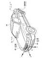
なお、例えば図2に示すように、赤外線カメラ2R,2Lは、自車両10の前部に、自車両10の車幅方向中心部に対してほぼ対象な位置に配置されており、2つの赤外線カメラ2R,2Lの光軸が互いに平行であって、かつ両者の路面からの高さが等しくなるように固定されている。なお、赤外線カメラ2R,2Lは、対象物の温度が高いほど、出力信号レベルが高くなる(つまり、輝度が増大する)特性を有している。
また、HUD7aは、自車両10のフロントウインドウの運転者の前方視界を妨げない位置に表示画面が表示されるように設けられている。For example, as shown in FIG. 2, the infrared cameras 2 </ b> R and 2 </ b> L are disposed at the front portion of the
Further, the
そして、各赤外線カメラ2R,2Lは、例えば図3に示すように、CCDやC−MOS等の撮影素子11と、画像出力部12と、カメラ内部の温度を検出する内部温度センサ13と、所定のフェール画像を記憶するフェール画像記憶部14とを備えて構成されている。
画像出力部12は、内部温度センサ13により検出されるカメラ内部の温度が所定温度以下である場合には、撮影素子11の撮影により得られた赤外線画像を画像処理ユニット1に出力し、内部温度センサ13により検出されるカメラ内部の温度が所定温度以上である場合には、撮影素子11の撮影により得られた赤外線画像の代わりにフェール画像記憶部14に記憶されている所定のフェール画像を画像処理ユニット1に出力する。Each
When the temperature inside the camera detected by the
そして、画像処理ユニット1は、例えば図3に示すように、画像メモリ21と、フェール判定部22と、電源制御部23と、復帰判定部24とを備えて構成され、特に、復帰判定部24には、ヨーレートセンサ3および車速センサ4およびブレーキセンサ5に加えて外気温センサや自車両に搭載された各種の温度センサ等を具備し、各種の車両状態量を検出する車両状態量センサ31から出力される検出信号が入力されていると共に、画像処理ユニット1のフェール判定部22には、スピーカ6および表示装置7を具備する報知装置22が接続されている。 For example, as shown in FIG. 3, the image processing unit 1 includes an
この画像処理ユニット1において、画像メモリ11は赤外線カメラ2R(または2L)から受信した赤外線画像をデジタルデータとして記憶する。
フェール判定部22は、赤外線カメラ2R(または2L)から所定のフェール画像が出力されているか否かを判定し、この判定結果が「YES」の場合には、例えば赤外線カメラ2R(または2L)が過剰な高温状態であって電源供給装置33による電力供給を停止することを報知する警報として、例えばスピーカ6を介した警報音や音声等の聴覚的警報や、例えば表示装置7を介した表示等の視覚的警報等を報知装置22から出力させると共に、電源制御部23を介して電源供給装置33から赤外線カメラ2R(または2L)への電力供給を停止させる。In this image processing unit 1, the
The
復帰判定部24は、電源供給装置33から赤外線カメラ2R(または2L)への電力供給が停止されている状態で所定状態が検知された場合に、電源制御部23を介して電源供給装置33から赤外線カメラ2R(または2L)への電力供給を再開させる。
この所定状態としては、例えば赤外線カメラ2R(または2L)への電力供給が停止された時点から所定時間(例えば、30秒等)が経過し、かつ、例えば車速センサ4にて検出される車速Vが所定車速(例えば、30km/h等)以上となること等によって赤外線カメラ2R(または2L)が冷却されたと推定され、かつ、外気温センサにて検出される外気温が所定温度以下となった状態等とされている。When the predetermined state is detected when the power supply from the
As this predetermined state, for example, a predetermined time (for example, 30 seconds) elapses from the time when power supply to the
本実施の形態による車両周辺監視装置は上記構成を備えており、次に、この車両周辺監視装置の動作、特に、赤外線カメラ2R(または2L)に対する電力供給を制御する処理について添付図面を参照しながら説明する。
まず、図4に示すステップS01においては、電源供給装置33から赤外線カメラ2R(または2L)への電力供給が停止状態であるか否かを判定する。
この判定結果が「YES」の場合には、後述するステップS07に進む。
一方、この判定結果が「NO」の場合には、ステップS02に進む。
ステップS02においては、内部温度センサ13により検出されるカメラ内部の温度を取得する。
次に、ステップS03においては、カメラ内部の温度が所定温度よりも高いか否かを判定する。
ステップS03の判定結果が「NO」の場合には、ステップS04に進み、このステップS04においては、撮影素子11の撮影により得られた赤外線画像を画像処理ユニット1に出力して、一連の処理を終了する。
一方、ステップS03の判定結果が「YES」の場合には、ステップS05に進む。The vehicle periphery monitoring apparatus according to the present embodiment has the above-described configuration. Next, referring to the accompanying drawings, the operation of the vehicle periphery monitoring apparatus, particularly the process for controlling the power supply to the
First, in step S01 shown in FIG. 4, it is determined whether or not the power supply from the
If this determination is “YES”, the flow proceeds to step S 07 described later.
On the other hand, if this determination is “NO”, the flow proceeds to step S 02.
In step S02, the temperature inside the camera detected by the
Next, in step S03, it is determined whether or not the temperature inside the camera is higher than a predetermined temperature.
If the determination result in step S03 is “NO”, the process proceeds to step S04. In this step S04, an infrared image obtained by photographing with the
On the other hand, if the determination result of step S03 is “YES”, the process proceeds to step S05.
そして、ステップS05においては、撮影素子11の撮影により得られた赤外線画像の代わりにフェール画像記憶部14に記憶されている所定のフェール画像を画像処理ユニット1に出力する。
そして、ステップS06においては、画像処理ユニット1のフェール判定部22が赤外線カメラ2R(または2L)から所定のフェール画像が出力されていることを判定し、画像処理ユニット1の電源制御部23により、電源供給装置33から赤外線カメラ2R(または2L)への電力供給を停止して、一連の処理を終了する。In step S05, a predetermined fail image stored in the fail
In step S06, the
また、ステップS07においては、例えば外気温センサにより検出される外気温や車速センサ4により検出される車速等の車両状態量を取得する。
そして、ステップS08においては、取得した車両状態量に基づき、所定状態が検知されたか否かを判定する。
この判定結果が「NO」の場合には、一連の処理を終了する。
一方、この判定結果が「YES」の場合には、ステップS09に進み、このステップS09においては、画像処理ユニット1の電源制御部23により、電源供給装置33から赤外線カメラ2R(または2L)への電力供給を開始して、一連の処理を終了する。In step S07, the vehicle state quantity such as the outside air temperature detected by the outside air temperature sensor or the vehicle speed detected by the vehicle speed sensor 4 is acquired.
In step S08, it is determined whether a predetermined state is detected based on the acquired vehicle state quantity.
When the determination result is “NO”, the series of processes is terminated.
On the other hand, if this determination is “YES”, the flow proceeds to step S 09, and in this step S 09, the
上述したように、本実施の形態による車両周辺監視装置によれば、各赤外線カメラ2R,2Lの温度を検知する内部温度センサ13,13を備えたことにより、各赤外線カメラ2R,2Lの温度状態を精度良く検知することができ、各赤外線カメラ2R,2Lの電源である電源供給装置33を適切に制御して各赤外線カメラ2R,2Lを保護することができる。
また、各赤外線カメラ2R,2Lの再起動時には、各赤外線カメラ2R,2Lの状態が所定の復帰可能状態であるか否かを判定することにより、各赤外線カメラ2R,2Lの電源である電源供給装置33を適切に制御して各赤外線カメラ2R,2Lを保護しつつ、再起動させることができる。As described above, according to the vehicle periphery monitoring device according to the present embodiment, the
Further, when each
1 画像処理ユニット
2R,2L 赤外線カメラ(撮像手段)
3 ヨーレートセンサ
4 車速センサ
5 ブレーキセンサ
6 スピーカ
7 表示装置
10 自車両
13 内部温度センサ(温度検知手段)
22 フェール判定部(オフ信号出力手段)
23 電源制御部(再起動手段)
24 復帰判定部(復帰判定手段、経過時間検出手段)
31 車両状態量センサ(車速検出手段、車両温度状態検出手段)
1
DESCRIPTION OF
22 Fail determination unit (off signal output means)
23 Power control unit (restart means)
24 Return determination unit (return determination means, elapsed time detection means)
31 Vehicle state quantity sensor (vehicle speed detection means, vehicle temperature state detection means)
Claims (2)
Translated fromJapanese前記撮像手段の温度を検知する温度検知手段と、
前記温度検知手段により検知された前記撮像手段の温度に応じて前記電源をオフ状態に設定する指令信号を出力するオフ信号出力手段と、
前記撮像手段の状態が所定の復帰可能状態であるか否かを判定する復帰判定手段と、
前記復帰判定手段にて前記撮像手段の状態が所定の復帰可能状態であると判定された場合に、前記電源がオフ状態に設定された前記撮像手段を再起動させる再起動手段と、
前記車両の速度を検出する車速検出手段と、
前記車両前部の温度状態を検出する外気温センサと、を備え、
前記復帰判定手段は、前記車速検出手段により検出された前記車両の速度が所定以上、かつ前記外気温センサにより検出された温度が所定以下、である場合に前記撮像手段の状態が所定の復帰可能状態であると判定することを特徴とする車両周辺監視装置。A vehicle periphery monitoring device that is mounted on the front of the vehicle and can control the power supply of an imaging means that images the periphery of the vehicle,
Temperature detecting means for detecting the temperature of the imaging means;
An off signal output means for outputting a command signal for setting the power supply in an off state according to the temperature of the imaging means detected by the temperature detection means;
Return determination means for determining whether or not the state of the imaging means is a predetermined returnable state;
A restarting means for restarting the imaging means whose power is set to an off state when the return determination means determines that the state of the imaging means is a predetermined returnable state;
Vehicle speed detection means for detecting the speed of the vehicle;
An outside air temperature sensor for detecting the temperature state of the front part of the vehicle,
The return determination means can return the imaging means to a predetermined state when the speed of the vehicle detected by the vehicle speed detection means is not less than a predetermined value and the temperature detected by the outside air temperature sensor is not more than a predetermined value. A vehicle periphery monitoring device characterized by determining that the vehicle is in a state.
前記復帰判定手段は、前記車速検出手段により検出された前記車両の速度が所定以上、かつ前記経過時間検出手段により検出された前記経過時間が所定以上、かつ前記外気温センサにより検出された温度が所定以下、である場合に前記撮像手段の状態が所定の復帰可能状態であると判定することを特徴とする請求項1に記載の車両周辺監視装置。Elapsed time detection means for detecting an elapsed time from the time when the command signal is output by the off signal output means,
The return determination means has a vehicle speed detected by the vehicle speed detection means greater than or equal to a predetermined value, and the elapsed time detected by the elapsed time detection means exceeds a predetermined value, and the temperature detected by the outside air temperature sensor. The vehicle periphery monitoring device according to claim 1, wherein when it is equal to or less than a predetermined value, the state of the imaging unit is determined to be a predetermined returnable state.
Priority Applications (2)
| Application Number | Priority Date | Filing Date | Title |
|---|---|---|---|
| JP2004347822AJP4242334B2 (en) | 2004-11-30 | 2004-11-30 | Vehicle periphery monitoring device |
| US11/287,868US8115809B2 (en) | 2004-11-30 | 2005-11-28 | Vehicle surroundings monitoring apparatus |
Applications Claiming Priority (1)
| Application Number | Priority Date | Filing Date | Title |
|---|---|---|---|
| JP2004347822AJP4242334B2 (en) | 2004-11-30 | 2004-11-30 | Vehicle periphery monitoring device |
Publications (2)
| Publication Number | Publication Date |
|---|---|
| JP2006151301A JP2006151301A (en) | 2006-06-15 |
| JP4242334B2true JP4242334B2 (en) | 2009-03-25 |
Family
ID=36567426
Family Applications (1)
| Application Number | Title | Priority Date | Filing Date |
|---|---|---|---|
| JP2004347822AExpired - Fee RelatedJP4242334B2 (en) | 2004-11-30 | 2004-11-30 | Vehicle periphery monitoring device |
Country Status (2)
| Country | Link |
|---|---|
| US (1) | US8115809B2 (en) |
| JP (1) | JP4242334B2 (en) |
Families Citing this family (20)
| Publication number | Priority date | Publication date | Assignee | Title |
|---|---|---|---|---|
| JP4376653B2 (en)* | 2004-02-17 | 2009-12-02 | 富士重工業株式会社 | Outside monitoring device |
| US8531562B2 (en) | 2004-12-03 | 2013-09-10 | Fluke Corporation | Visible light and IR combined image camera with a laser pointer |
| JP5125392B2 (en)* | 2007-10-16 | 2013-01-23 | 日産自動車株式会社 | Hood flip-up device and detection characteristic correction method for hood flip-up device |
| JP4708443B2 (en)* | 2008-01-31 | 2011-06-22 | トヨタ自動車株式会社 | Operation control map and white line recognition device |
| JP5457100B2 (en)* | 2009-08-04 | 2014-04-02 | オリンパスイメージング株式会社 | Image capturing apparatus and image capturing apparatus control method |
| JP5685818B2 (en)* | 2010-02-10 | 2015-03-18 | ソニー株式会社 | IMAGING DEVICE AND IMAGING DEVICE POWER SUPPLY CONTROL METHOD |
| JP5486031B2 (en)* | 2012-03-06 | 2014-05-07 | 本田技研工業株式会社 | Light distribution control device |
| JP5768758B2 (en)* | 2012-04-26 | 2015-08-26 | 株式会社デンソー | In-vehicle camera control device |
| WO2014080521A1 (en) | 2012-11-26 | 2014-05-30 | パイオニア株式会社 | Display device, control method, program, and storage medium |
| JP6519355B2 (en)* | 2015-06-30 | 2019-05-29 | 株式会社デンソー | Camera apparatus and in-vehicle system |
| CN105035322B (en)* | 2015-07-07 | 2017-08-25 | 范充 | The purchase method of automobile carrying flight instruments |
| JP2017144937A (en)* | 2016-02-19 | 2017-08-24 | トヨタ自動車株式会社 | Imaging system |
| DE102017208663B4 (en)* | 2016-06-09 | 2024-12-05 | Conti Temic Microelectronic Gmbh | Environment-sensing device and motor vehicle with such an environment-sensing device |
| CN110892443B (en)* | 2017-08-01 | 2024-01-09 | 松下知识产权经营株式会社 | Personal authentication device |
| JP7141242B2 (en)* | 2018-05-18 | 2022-09-22 | 株式会社小糸製作所 | sensor system |
| CN109256747B (en)* | 2018-09-28 | 2020-03-17 | 国网福建省电力有限公司 | Online calibrating device of infrared temperature sensing protection in electric power high-voltage board |
| CN109256753B (en)* | 2018-09-28 | 2020-03-17 | 国网福建省电力有限公司 | Calibration method of infrared temperature sensing protection online calibration device in electric power high-voltage cabinet |
| US11153950B2 (en)* | 2019-02-14 | 2021-10-19 | Orlaco Products B.V. | Replacement mirror system with IR LED overheating management |
| JP6877604B1 (en)* | 2020-02-20 | 2021-05-26 | 三菱電機株式会社 | In-vehicle camera device and in-vehicle camera component temperature estimation method |
| JP7626008B2 (en) | 2021-08-26 | 2025-02-04 | トヨタ自動車株式会社 | In-vehicle camera |
Family Cites Families (19)
| Publication number | Priority date | Publication date | Assignee | Title |
|---|---|---|---|---|
| DE3624171A1 (en)* | 1986-07-17 | 1988-01-21 | Bosch Gmbh Robert | HEATING AND / OR AIR CONDITIONING FOR MOTOR VEHICLES |
| JPH08276731A (en) | 1995-02-07 | 1996-10-22 | Paramaunto Corp:Kk | Automobile |
| JPH08313632A (en) | 1995-05-19 | 1996-11-29 | Omron Corp | Alarm generator, alarm generating method and vehicle mounting alarm generator |
| JP4135123B2 (en) | 1998-05-13 | 2008-08-20 | 日産自動車株式会社 | Display processing device |
| JP3716623B2 (en) | 1998-07-09 | 2005-11-16 | 日産自動車株式会社 | Thermal detector |
| JP3515926B2 (en) | 1999-06-23 | 2004-04-05 | 本田技研工業株式会社 | Vehicle periphery monitoring device |
| JP3462812B2 (en) | 1999-09-22 | 2003-11-05 | 富士重工業株式会社 | Power supply control method and device for vehicle-mounted camera |
| JP3824828B2 (en)* | 1999-12-14 | 2006-09-20 | 本田技研工業株式会社 | Engine control device |
| JP2001211449A (en) | 2000-01-27 | 2001-08-03 | Honda Motor Co Ltd | Vehicle image recognition device |
| JP2001213240A (en) | 2000-02-04 | 2001-08-07 | Hitachi Ltd | In-vehicle camera device |
| JP2001351200A (en) | 2000-06-09 | 2001-12-21 | Nissan Motor Co Ltd | In-vehicle object detection device |
| JP2002247371A (en)* | 2001-02-21 | 2002-08-30 | Ricoh Co Ltd | Image processing apparatus and recording medium recording image processing program |
| JP3732115B2 (en) | 2001-05-23 | 2006-01-05 | 三菱電機株式会社 | Image processing device |
| DE60226817D1 (en)* | 2001-08-23 | 2008-07-10 | Nissan Motor | Driving Assistance System |
| JP2003189460A (en) | 2001-12-17 | 2003-07-04 | Yazaki Corp | Overcurrent protection circuit |
| JP4104867B2 (en) | 2002-01-18 | 2008-06-18 | 本田技研工業株式会社 | Night vision system |
| US7246656B2 (en)* | 2002-10-30 | 2007-07-24 | Denso Corporation | Vehicle air conditioner |
| PT1625664E (en)* | 2003-05-22 | 2011-02-09 | Pips Technology Inc | Automated site security, monitoring and access control system |
| JP2005186919A (en)* | 2003-12-04 | 2005-07-14 | Keihin Corp | Air conditioner for vehicles |
- 2004
- 2004-11-30JPJP2004347822Apatent/JP4242334B2/ennot_activeExpired - Fee Related
- 2005
- 2005-11-28USUS11/287,868patent/US8115809B2/enactiveActive
Also Published As
| Publication number | Publication date |
|---|---|
| JP2006151301A (en) | 2006-06-15 |
| US8115809B2 (en) | 2012-02-14 |
| US20060115120A1 (en) | 2006-06-01 |
Similar Documents
| Publication | Publication Date | Title |
|---|---|---|
| JP4242334B2 (en) | Vehicle periphery monitoring device | |
| JP5503730B2 (en) | Vehicle periphery monitoring device | |
| JP5768758B2 (en) | In-vehicle camera control device | |
| JP6844568B2 (en) | Extra findings determination device, extra findings determination system, extra findings determination method, program | |
| JP2010033106A (en) | Driver support device, driver support method, and driver support processing program | |
| JP2005096554A (en) | Tire pressure monitoring system | |
| JP2007094618A (en) | Notification controller and notification control method, recording medium, and program | |
| JP2008027309A (en) | Collision determination system and collision determination method | |
| JP2006235732A (en) | Drive recorder | |
| JP6947099B2 (en) | Extra findings determination device, extra findings determination system, extra findings determination method, program | |
| JP2008242725A (en) | Image data recording system and integrated circuit device | |
| JP2021157831A (en) | Looking-away determination device, looking-away determination system, looking-away determination method, program | |
| KR101546893B1 (en) | System for checking doze at the vehicle | |
| JP6535884B2 (en) | Electronic mirror device, control program of electronic mirror device | |
| JP2005153660A5 (en) | ||
| JP7259957B2 (en) | Judgment system, processing method, program | |
| JP2021051655A (en) | Notification device and notification method | |
| US12080081B2 (en) | Inattentiveness determination device, inattentiveness determination system, inattentiveness determination method, and storage medium for storing program | |
| JP2007038773A (en) | In-vehicle camera inspection device | |
| KR20070019166A (en) | Heat sensitive collision prevention system for vehicles and its control method | |
| JP2017061216A (en) | In-vehicle imaging system, vehicle, and imaging method | |
| JP2022059311A (en) | Imaging control device, imaging control method and program | |
| TWI549846B (en) | Environmental failure judgment system and method for automatic assisted driving | |
| JP3732115B2 (en) | Image processing device | |
| JP2007174113A (en) | Obstacle detection system and obstacle detection method |
Legal Events
| Date | Code | Title | Description |
|---|---|---|---|
| A131 | Notification of reasons for refusal | Free format text:JAPANESE INTERMEDIATE CODE: A131 Effective date:20080902 | |
| A521 | Request for written amendment filed | Free format text:JAPANESE INTERMEDIATE CODE: A523 Effective date:20081021 | |
| A131 | Notification of reasons for refusal | Free format text:JAPANESE INTERMEDIATE CODE: A131 Effective date:20081111 | |
| A521 | Request for written amendment filed | Free format text:JAPANESE INTERMEDIATE CODE: A523 Effective date:20081125 | |
| TRDD | Decision of grant or rejection written | ||
| A01 | Written decision to grant a patent or to grant a registration (utility model) | Free format text:JAPANESE INTERMEDIATE CODE: A01 Effective date:20081216 | |
| A01 | Written decision to grant a patent or to grant a registration (utility model) | Free format text:JAPANESE INTERMEDIATE CODE: A01 | |
| A61 | First payment of annual fees (during grant procedure) | Free format text:JAPANESE INTERMEDIATE CODE: A61 Effective date:20081224 | |
| FPAY | Renewal fee payment (event date is renewal date of database) | Free format text:PAYMENT UNTIL: 20120109 Year of fee payment:3 | |
| R150 | Certificate of patent or registration of utility model | Free format text:JAPANESE INTERMEDIATE CODE: R150 | |
| FPAY | Renewal fee payment (event date is renewal date of database) | Free format text:PAYMENT UNTIL: 20120109 Year of fee payment:3 | |
| FPAY | Renewal fee payment (event date is renewal date of database) | Free format text:PAYMENT UNTIL: 20130109 Year of fee payment:4 | |
| FPAY | Renewal fee payment (event date is renewal date of database) | Free format text:PAYMENT UNTIL: 20130109 Year of fee payment:4 | |
| FPAY | Renewal fee payment (event date is renewal date of database) | Free format text:PAYMENT UNTIL: 20140109 Year of fee payment:5 | |
| LAPS | Cancellation because of no payment of annual fees |