JP4242162B2 - Light source device - Google Patents
Light source deviceDownload PDFInfo
- Publication number
- JP4242162B2 JP4242162B2JP2003010211AJP2003010211AJP4242162B2JP 4242162 B2JP4242162 B2JP 4242162B2JP 2003010211 AJP2003010211 AJP 2003010211AJP 2003010211 AJP2003010211 AJP 2003010211AJP 4242162 B2JP4242162 B2JP 4242162B2
- Authority
- JP
- Japan
- Prior art keywords
- light
- degrees
- prism
- light source
- range
- Prior art date
- Legal status (The legal status is an assumption and is not a legal conclusion. Google has not performed a legal analysis and makes no representation as to the accuracy of the status listed.)
- Expired - Fee Related
Links
Images


Landscapes
- Liquid Crystal (AREA)
- Planar Illumination Modules (AREA)
- Light Guides In General And Applications Therefor (AREA)
- Optical Elements Other Than Lenses (AREA)
Abstract
Description
Translated fromJapanese【0001】
【発明の属する技術分野】
本発明は、ノートパソコン、液晶テレビ、携帯電話、携帯情報端末等において表示部として使用される液晶表示装置等を構成するエッジライト方式の光源装置に関る。
【0002】
【従来の技術】
近年、カラー液晶表示装置は、携帯用ノートパソコンやパソコン等のモニターとして、あるいは液晶テレビやビデオ一体型液晶テレビ、携帯電話、携帯情報端末等の表示部として、種々の分野で広く使用されてきている。また、情報処理量の増大化、ニーズの多様化、マルチメディア対応等に伴って、液晶表示装置の大画面化、高精細化が盛んに進められている。
【0003】
液晶表示装置は、基本的にバックライト部と液晶表示素子部とから構成されている。バックライト部としては、液晶表示素子部の直下に光源を配置した直下方式のものや導光体の側端面に対向するように光源を配置したエッジライト方式のものがあり、液晶表示装置のコンパクト化の観点からエッジライト方式が多用されている。
【0004】
ところで、近年、比較的小さな画面寸法の表示装置であって観察方向範囲の比較的狭い例えば携帯電話機の表示部として使用される液晶表示装置等では、消費電力の低減の観点から、エッジライト方式のバックライト部として、一次光源から発せられる光量を有効に利用するために、画面から出射する光束の広がり角度をできるだけ小さくして所要の角度範囲に集中して光を出射させるものが利用されてきている。
【0005】
このように観察方向範囲が限定される表示装置であって、一次光源の光量の利用効率を高め消費電力を低減するために比較的狭い範囲に集中して光出射を行う光源装置として、本出願人は、特開2002−143515号公報(特許文献1)において、導光体の光出射面に隣接して両面にプリズム形成面を有するプリズムシートを使用することを提案している。
【0006】
【特許文献1】
特開2002−143515号公報
【0007】
【発明が解決しようとする課題】
この両面プリズムシートでは、一方の面である入光面及び他方の面である出光面のそれぞれに、互いに平行な複数のプリズム列が形成されており、入光面と出光面とでプリズム列方向を合致させ且つプリズム列どうしを対応位置に配置している。これにより、導光体の光出射面から該光出射面に対して傾斜した方向に出射光のピークを持ち適宜の角度範囲に分布して出射する光を、プリズムシートの入光面の一方のプリズム面から入射させ他方のプリズム面で内面反射させ、更に出光面のプリズムでの屈折作用を受けさせて、比較的狭い所要方向へ光を集中出射させる。
【0008】
この光源装置によれば、狭い角度範囲の集中出射が可能であるが、光偏向素子として使用されるプリズムシートとして両面に互いに平行な複数のプリズム列を、入光面と出光面とでプリズム列方向を合致させ且つプリズム列どうしを対応位置に配置することが必要であり、この成形が複雑になる。
【0009】
また、このような狭い角度範囲に集中して出射された光が強いぎらつきを引き起こすため、バックライトの品位に劣るという問題も有していた。さらに、このような視野角の狭い光源装置は、小型のバックライトでは問題はないが、4インチ以上の液晶表示装置用のバックライト、特に12〜15インチ程度のノ−トパソコン用液晶表示装置に使用されるバックライトとしては視野角が狭く、視認性に劣るという問題をも有していた。
【0010】
そこで、本発明の目的は、一次光源の光利用効率に優れた高輝度特性を損なうことなく、視野角特性および画像形成用証明としての品位に優れた光源装置を提供することにある。
【0011】
【課題を解決するための手段】
すなわち、本発明の光源装置は、一次光源と、該一次光源から発せられる光を入射する
光入射面及び入射した光を導光して出射する光出射面を有する導光体と、該導光体の光出射面に隣接配置される光偏向素子と、該光偏向素子の出光面上に隣接配置される光拡散素子とを少なくとも備えた光源装置であって、
前記光偏向素子は前記導光体の光出射面に対向して位置する入光面とその反対側の出光面とを有しており、該入光面には互いに並列に配列された複数のプリズム列が形成されており、該プリズム列は2つのプリズム面を有しており、少なくとも一方のプリズム面の少なくとも一部が凸曲面形状をなしており、前記凸曲面形状は、前記プリズム列において前記少なくとも一方の面の側において、前記プリズム列の頂部と谷部とを結ぶ直線から最大距離d突出した形状であり、前記プリズム列の配列ピッチPと、前記最大距離dとの比(d/P)が0.05〜5%の範囲内である形状であり、前記光拡散素子は平行光を入射したときの出射光光度分布の半値全幅が1〜13度であることを特徴とするものである。また、本発明の光源装置は、一次光源と、該一次光源から発せられる光を入射する光入射面及び入射した光を導光して出射する光出射面を有する導光体と、該導光体の光出射面に隣接配置される光偏向素子と、該光偏向素子の出光面上に隣接配置される光拡散素子とを少なくとも備えた光源装置であって、前記光偏向素子は前記導光体の光出射面に対向して位置する入光面とその反対側の出光面とを有しており、該入光面には互いに並列に配列された複数のプリズム列が形成されており、該プリズム列は2つのプリズム面を有しており、少なくとも一方のプリズム面の少なくとも一部が凸曲面形状をなしており、前記凸曲面形状は、前記プリズム列において前記少なくとも一方の面の側において、前記プリズム列の頂部と谷部とを結ぶ直線から最大距離d突出した形状であり、前記プリズム列の配列ピッチPと、前記最大距離dとの比(d/P)が0.05〜5%の範囲内である形状であり、前記光拡散素子の少なくとも一方の面の平均傾斜角が0.8〜12度であることを特徴とするものである。
【0012】
また、本発明の光源装置は、一次光源と、該一次光源から発せられる光を入射する光入射面及び入射した光を導光して出射する光出射面を有する導光体と、該導光体の光出射面に隣接配置される光偏向素子と、該光偏向素子の出光面上に隣接配置される光拡散素子とを少なくとも備えた光源装置であって、前記光偏向素子は前記導光体の光出射面に対向して位置する入光面とその反対側の出光面とを有しており、該入光面には互いに並列に配列された複数のプリズム列が形成されており、該プリズム列は2つのプリズム面を有しており、少なくとも一方のプリズム面の少なくとも一部が凸曲面形状をなしており、前記光偏向素子からの出射光輝度分布の半値全幅が19〜26度であり、前記光拡散素子の平行光を入射したときの出射光輝度分布の半値全幅が1〜8度であることを特徴とするものである。
【0013】
また、本発明の光源装置は、一次光源と、該一次光源から発せられる光を入射する互いに対向配置してなる2つの光入射面及び入射した光を導光して出射する光出射面を有し、展開長が8cmを超え28cm以下である導光体と、該導光体の光出射面に隣接配置される光偏向素子と、該光偏向素子の出光面上に隣接配置される光拡散素子とを少なくとも備えた光源装置であって、前記光偏向素子は前記導光体の光出射面に対向して位置する入光面とその反対側の出光面とを有しており、該入光面には互いに並列に配列された複数のプリズム列が形成されており、該プリズム列は2つのプリズム面を有しており、少なくとも一方のプリズム面の少なくとも一部が凸曲面形状をなしており、前記光拡散素子は平行光を入射したときの出射光光度分布の半値全幅が0.7〜6度であることを特徴とするものである。
【0014】
また、本発明の光源装置は、一次光源と、該一次光源から発せられる光を入射する光入射面及び入射した光を導光して出射する光出射面を有する導光体と、該導光体の光出射面に隣接配置される光偏向素子と、前記光偏向素子の出光面上に隣接配置される光拡散素子とを少なくとも備えた光源装置であって、該光拡散素子は平行光を入射したときの出射光光度分布の半値全幅が異方性を有していることを特徴とするものである。
【0015】
【発明の実施の形態】
以下、図面を参照しながら、本発明の実施の形態を説明する。
【0016】
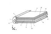
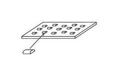
図1は、本発明による面状の光源装置(面光源装置)の一つの実施形態を示す模式的斜視図である。図1に示されているように、本発明の光源装置は、少なくとも一つの側端面を光入射面31とし、これと略直交する一つの表面を光出射面33とする導光体3と、この導光体3の光入射面31に対向して配置され光源リフレクタ2で覆われた一次光源1と、導光体3の光出射面上に配置された光偏向素子4と、光偏向素子4の出光面42上に配置された光拡散素子6、導光体3の光出射面33の裏面34に対向して配置された光反射素子5とから構成される。
【0017】
導光体3は、XY面と平行に配置されており、全体として矩形板状をなしている。導光体3は4つの側端面を有しており、そのうちYZ面と平行な1対の側端面のうちの少なくとも一つの側端面を光入射面31とする。光入射面31は光源1と対向して配置されており、光源1から発せられた光は光入射面31から導光体3内へと入射する。本発明においては、例えば、光入射面31と対向する側端面32等の他の側端面にも光源を配置してもよい。
【0018】
導光体3の光入射面31に略直交した2つの主面は、それぞれXY面と略平行に位置しており、いずれか一方の面(図では上面)が光出射面33となる。この光出射面33またはその裏面34のうちの少なくとも一方の面に粗面からなる指向性光出射機能部や、プリズム列、レンチキュラーレンズ列、V字状溝等の多数のレンズ列を光入射面31と略平行に並列形成したレンズ面からなる指向性光出射機能部等を付与することによって、光入射面31から入射した光を導光体3中を導光させながら光出射面33から光入射面31および光出射面33に直交する面(XZ面)内において指向性のある光を出射させる。このXZ面内分布における出射光光度分布のピークの方向が光出射面33となす角度をαとする。該角度αは例えば10〜40度であり、出射光光度分布の半値全幅は例えば10〜40度である。
【0019】
導光体3の表面に形成する粗面やレンズ列は、ISO4287/1−1984による平均傾斜角θaが0.5〜15度の範囲のものとすることが、光出射面33内での輝度の均斉度を図る点から好ましい。平均傾斜角θaは、さらに好ましくは1〜12度の範囲であり、より好ましくは1.5〜11度の範囲である。この平均傾斜角θaは、導光体3の厚さ(t)と入射光が伝搬する方向の長さ(L)との比(L/t)によって最適範囲が設定されることが好ましい。すなわち、導光体3としてL/tが20〜200程度のものを使用する場合は、平均傾斜角θaを0.5〜7.5度とすることが好ましく、さらに好ましくは1〜5度の範囲であり、より好ましくは1.5〜4度の範囲である。また、導光体3としてL/tが20以下程度のものを使用する場合は、平均傾斜角θaを7〜12度とすることが好ましく、さらに好ましくは8〜11度の範囲である。
【0020】
導光体3に形成される粗面の平均傾斜角θaは、ISO4287/1−1984に従って、触針式表面粗さ計を用いて粗面形状を測定し、測定方向の座標をxとして、得られた傾斜関数f(x)から次の(1)式および(2)式を用いて求めることができる。ここで、Lは測定長さであり、Δaは平均傾斜角θaの正接である。
【0021】
【数1】
【0022】
本発明において、導光体3からの光出射率は次のように定義される。光出射面33の光入射面31側の端縁での出射光の光強度(I0 )と光入射面31側の端縁から距離Lの位置での出射光強度(I)との関係は、導光体3の厚さ(Z方向寸法)をtとすると、次の(3)式のような関係を満足する。
【0023】
【数2】
【0024】
また、指向性光出射機能部が付与されていない他の主面には、導光体3からの出射光の光源1と平行な面(YZ面)での指向性を制御するために、光入射面31に対して略垂直の方向(X方向)に延びる多数のレンズ列を配列したレンズ面を形成することが好ましい。図1に示した実施形態においては、光出射面33に粗面を形成し、裏面34に光入射面31に対して略垂直方向(X方向)に延びる多数のレンズ列の配列からなるレンズ面を形成している。本発明においては、図1に示した形態とは逆に、光出射面33にレンズ面を形成し、裏面34を粗面とするものであってもよい。
【0025】
図1に示したように、導光体3の裏面34あるいは光出射面33にレンズ列を形成する場合、そのレンズ列としては略X方向に延びたプリズム列、レンチキュラーレンズ列、V字状溝等が挙げられるが、YZ方向の断面の形状が略三角形状のプリズム列とすることが好ましい。
【0026】
本発明において、導光体3に形成されるレンズ列としてプリズム列を形成する場合には、その頂角を70〜150度の範囲とすることが好ましい。これは、頂角をこの範囲とすることによって導光体3からの出射光を十分集光さることができ、光源装置としての輝度の十分な向上を図ることができるためである。すなわち、プリズム頂角をこの範囲内とすることによって、出射光光度分布におけるピーク光を含みXZ面に垂直な面において出射光光度分布の半値全幅が35〜65度である集光された出射光を出射させることができ、光源装置としての輝度を向上させることができる。なお、プリズム列を光出射面33に形成する場合には、頂角は80〜100゜の範囲とすることが好ましく、プリズム列を裏面34に形成する場合には、頂角は70〜80゜または100〜150゜の範囲とすることが好ましい。
【0027】
なお、本発明では、上記のような光出射面33またはその裏面34に光出射機能部を形成する代わりにあるいはこれと併用して、導光体内部に光拡散性微粒子を混入分散することで指向性光出射機能を付与したものでもよい。また、導光体3としては、図1に示したような形状に限定されるものではなく、くさび状、船型状等の種々の形状のものが使用できる。
【0028】
光偏向素子4は、導光体3の光出射面33上に配置されている。光偏向素子4の2つの主面41,42は互いに対向しており、それぞれ全体としてXY面と平行に位置する。主面41,42のうちの一方(導光体3の光出射面33側に位置する主面)は入光面41とされており、他方が出光面42とされている。出光面42は、導光体3の光出射面33と平行な平坦面とされている。入光面41は、多数のY方向に延びるプリズム列が互いに平行に配列されたプリズム形成面とされている。プリズム形成面は、隣接するプリズム列の間に比較的幅の狭い平坦部(例えば、プリズム列ピッチと同程度あるいはそれより小さい幅の平坦部)を設けてもよいが、光の利用効率を高める点からは平坦部を設けることなくプリズム列を連続して形成することが好ましい。
【0029】
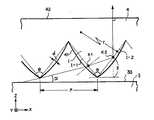
図2は、光偏向素子4の入光面41のプリズム列の形状の説明図である。入光面41のプリズム列の形状は、次のようにして設定されている。
【0030】
即ち、プリズム列配列のピッチをPとして、先ず、断面三角形状の仮想プリズム列Iを設定する。この仮想プリズム列Iの2つのプリズム面I−1,I−2のなす角度(即ち仮想プリズム頂角)をθとする。この仮想プリズム頂角θは、導光体3の光出射面33から到来する光のXZ面内の出射光光度分布のピーク光(傾斜角α)が仮想プリズム列Iに入射して仮想プリズム面I−2により内面全反射された上で、例えば出光面42の法線方向へと進行するように設定されている。仮想プリズム頂角θは、例えば、光偏向素子4の出光面42から出射される光のピーク光を出光面42の法線方向近傍(例えば、法線方向から±10度の範囲内)へ向ける場合には、50〜80度とすることが好ましく、さらに好ましくは55〜75度の範囲であり、より好ましくは60〜70度の範囲である。また、仮想プリズム列の一方のプリズム面の傾斜角(出光面42に対してなす角度)は、導光体3からの出射光を光偏向素子4で効率よくの所望の方向に偏向させることから45度以上とすることが好ましく、さらに好ましくは47度以上、より好ましくは50度以上である。
【0031】
次に、以上のようにして形状が設定された仮想プリズム列Iの形状を基準として、その少なくとも一方のプリズム面が凸曲面形状となるように実際のプリズム列の形状を定める。具体的には、次のようにして実際のプリズム列の形状を定めることが好ましい。導光体3の光出射面33から出射する光の出射光光度分布(XZ面内)のピーク光(傾斜角α)が一次光源1側の隣接仮想プリズム列の頂部をかすめて仮想プリズムIに入射する仮想光を設定し、この仮想光が仮想プリズム面I−1を通過する位置をK1とし、仮想プリズム面I−2に到達する位置をK2とする。
【0032】
通常は、位置K2よりも出光面42に近い全面を凸曲面形状とすることが好ましい。一方、仮想プリズム列Iにおけるプリズム面I−2の内面全反射位置K2よりも入光面41に近い位置(即ち、出光面42から遠い位置)では、平面形状としてもよく凸曲面形状としてもよい。いずれの場合も、位置K2の出光面42側近傍のプリズム面形状を延長するような形状とすることが好ましく、プリズム列の頂部は仮想プリズム列の頂部と一致しなくてもよい。
【0033】
プリズム列の形状は、仮想プリズム列Iにおけるプリズム面I−2の内面全反射位置K2よりも出光面42に近い位置では、その少なくとも一部または全部にプリズム面の傾斜角が仮想プリズム列Iのプリズム面I−2の傾斜角よりも大きな傾斜角をもつような凸曲面形状とすることが好ましい。
【0034】
これは、図2に示されている寸法z(プリズム列の頂点と仮想プリズム面I−2の内面反射位置K2との間のZ方向距離)が以下の式(4):
【数3】
【数4】
【0035】
入光面41のプリズム列の形状をこのように設定することで、光偏向素子4から出射する光の輝度分布角度(半値全幅)を小さくすることができる。その理由は次のとおりである。即ち、仮想プリズム列Iにおけるプリズム面I−2の内面全反射位置K2よりも出光面42に近い位置に到達する光は、一次光源側の隣接仮想プリズム列の頂部よりも下側からαより大きな傾斜角で入射する光線の集合である。従って、そのピーク光の方向は、αより大きな傾斜の方向であり、その内面全反射光のピーク光の方向は出光面42の法線方向から内面全反射の仮想プリズム面に沿った方向の方へと傾斜した方向となる。このような光は出光面42からの出射光の輝度分布を広げる作用をなす。そこで、特定方向へ光量を集中して出射させるために、仮想プリズム列Iにおけるプリズム面I−2の内面全反射位置K2よりも出光面42に近い位置で、その少なくとも一部を実際のプリズム列のプリズム面の傾斜角を、対応する仮想プリズム面の傾斜角より大きくすることで、この領域で実際に内面全反射された光の進行方向を仮想プリズム面での反射光よりも出光面42の法線方向の方へと移動させるように修正することができ、高輝度化、狭視野化を図ることができる。
【0036】
以上のような凸曲面形状は、仮想プリズム列Iにおけるプリズム面I−2の内面全反射位置K2よりも出光面42に近い位置全体に形成して、内面全反射位置K2よりも出光面42から遠い位置では仮想プリズム列のプリズム面I−2のままの形状とすることもでき、内面全反射位置K2よりも出光面42から遠い位置も含めてプリズム面全体を凸曲面形状とすることもできる。このような凸曲面形状としては、仮想プリズム列と少なくとも底部を共通にした曲率半径rの凸円柱面形状を例示することができる。
【0037】
ここで、ピッチPで規格化した曲率半径rの値(r/P)としては、2〜80の範囲とすることが好ましく、より好ましくは7〜30の範囲であり、さらに好ましくは8〜20の範囲である。これは、r/Pをこの範囲とすることによって光偏向素子4の出光面42から出射する出射光輝度分布(XZ面内)の半値全幅を十分に狭くでき、光源装置としての輝度を十分に高くすることができるためである。例えば、プリズム列のピッチが40〜60μmである場合には、曲率半径rは、250〜3000μmの範囲とすることが好ましく、より好ましくは350〜1000μmの範囲であり、さらに好ましくは400〜700μmの範囲である。
【0038】
また、光偏向素子4の各プリズム列の凸曲面形状としては、仮想プリズム列のプリズム面と凸曲面形状のプリズム面の最大距離dと前記プリズム列の配列ピッチPとの比(d/P)が0.05〜5%の範囲となるような比較的緩やかな曲面形状とすることが好ましく、より好ましくは0.1〜3%の範囲であり、さらに好ましくは0.2〜2%の範囲である。これは、d/Pが5%を超えると光偏向素子4による集光効果が損なわれ光の発散が起こる傾向にあり、光偏向素子4の出光面42から出射する出射光輝度分布(XZ面内)の半値全幅を十分に狭くできなくなる傾向にあるためである。逆に、d/Pが0.05%未満であると光偏向素子4による集光効果が不十分となる傾向にあり、光偏向素子4の出光面42から出射する出射光輝度分布(XZ面内)の半値全幅を十分に狭くできなくなる傾向にあるためである。
【0039】
なお、本発明においては、光偏向素子4の各プリズム列の凸曲面形状は、上記のような曲率半径rの断面円弧状のものに限らず、上記のようなd/Pの範囲内であれば非球面状の凸曲面形状であってもよい。
【0040】
本発明において、上記のような凸曲面形状のプリズム面は、少なくとも一次光源1から遠い側の面に形成することが好ましい。これによれば、導光体3の端面32にも一次光源1を配置する場合の光偏向素子4から出射する光の輝度分布を十分に小さくすることができる。凸曲面形状のプリズム面は、例えば、導光体3を伝搬する光が光入射面31と反対側の端面32で反射して戻ってくる割合が比較的高い場合には、一次光源1に近い側のプリズム面も凸曲面形状とすることがより好ましい。特に、一次光源1に近い側のプリズム面を出光面42の法線方向に関して仮想プリズム面I−2に対応する実際のプリズム面と対称的な形状にするのが好ましい。一方、導光体3を伝搬する光が光入射面31と反対側の端面32で反射して戻ってくる割合が比較的低い場合には、一次光源1に近い側のプリズム面を平面としてもよい。また、導光体3に光偏向素子4を載置した際のスティッキング現象の発生を抑止する目的でプリズム列の頂部を尖鋭にすること(頂部先端のエッジを明確に形成すること)が必要な場合には、一次光源1に近い側のプリズム面を平面とすることが、双方のプリズム面を凸曲面とした場合に比べてプリズム列形成のための成形用型部材の形状転写面形状のより正確な形成が可能になることに基づきプリズム列頂部を尖鋭に形成することが容易になることから好ましい。
【0041】
本発明の光偏向素子においては、所望のプリズム形状を精確に作製し、安定した光学性能を得るとともに、組立作業時や光源装置としての使用時におけるプリズム頂部の摩耗や変形を抑止する目的で、プリズム列の頂部に平坦部あるいは曲面部を形成してもよい。この場合、プリズム頂部に形成する平坦部あるいは曲面部の幅は、3μm以下とすることが、光源装置としての輝度の低下やスティキング現象による輝度の不均一パターンの発生を抑止する観点から好ましく、より好ましくは2μm以下であり、さらに好ましくは1μm以下である。
【0042】
このように、導光体3の光出射面33上に上記のような光偏向素子4を、そのプリズム列形成面が入光面側となるように載置することによって、導光体3の光出射面33から出射する指向性出射光のXZ面内での出射光光度分布をより狭くすることができ、光源装置としての高輝度化、狭視野化を図ることができる。このような光偏向素子4からの出射光のXZ面内での出射光輝度分布の半値全幅は、5〜26度の範囲であることが好ましく、より好ましくは10〜20度の範囲であり、さらに好ましくは12〜18度の範囲である。これは、この出射光輝度分布(XZ面内)の半値全幅を5度以上とすることによって極端な狭視野化による画像等の見づらさをなくすことができ、26度以下とすることによって高輝度化と狭視野化を図ることができるためである。
【0043】
本発明における光偏向素子4の狭視野化は、導光体3の光出射面33からの出射光光度分布(XZ面内)の広がりの程度(半値全幅)に影響されるため、光偏向素子4の出光面42からの出射光輝度分布(XZ面内)の半値全幅Aの導光体3の光出射面33からの出射光光度分布(XZ面内)の半値全幅Bに対する割合も、導光体3からの出射光光度分布(XZ面内)の半値全幅Bによって変わる。例えば、導光体3からの出射光光度分布(XZ面内)の半値全幅Bが26度未満の場合には、半値全幅Aが半値全幅Bの30〜95%の範囲であることが好ましく、より好ましくは30〜80%の範囲であり、さらに好ましくは30〜70%の範囲である。また、導光体3からの出射光光度分布(XZ面内)の半値全幅Bが26度以上の場合には、半値全幅Aが半値全幅Bの30〜80%の範囲であることが好ましく、より好ましくは30〜70%の範囲であり、さらに好ましくは30〜60%の範囲である。特に、導光体3からの出射光光度分布(XZ面内)の半値全幅Bが26〜36度の場合には、半値全幅Aが半値全幅Bの30〜80%の範囲であることが好ましく、より好ましくは30〜70%の範囲であり、さらに好ましくは30〜60%の範囲である。さらに、導光体3からの出射光光度分布(XZ面内)の半値全幅Bが36度を超える場合には、半値全幅Aが半値全幅Bの30〜70%の範囲であることが好ましく、より好ましくは30〜60%の範囲であり、さらに好ましくは30〜50%の範囲である。
【0044】
このように、本発明においては、導光体3からの出射光光度分布(XZ面内)の半値全幅が大きいものほど狭視野化の効果は大きくなるため、狭視野化の効率という点では出射光光度分布(XZ面内)の半値全幅Bが26度以上である導光体3との組み合わせで光偏向素子4を使用することが好ましく、より好ましくは半値全幅Bが36度を超える導光体3である。また、導光体3からの出射光光度分布(XZ面内)の半値全幅が小さい場合には狭視野化の効果は小さくなるが、導光体3からの出射光光度分布(XZ面内)の半値全幅が小さいものほど高輝度化を図ることができるため、高輝度化という点では出射光光度分布(XZ面内)の半値全幅Bが26度未満である導光体3との組み合わせで光偏向素子4を使用することが好ましい。
【0045】
さらに、本発明においては、このように光偏向素子4によって狭視野化され高輝度化された光源装置において、輝度の低下をできる限り招くことなく、視野範囲を目的に応じて適度に制御するために、光偏向素子4の出光面上に光拡散素子6を隣接配置する。また、本発明においては、このように光拡散素子6を配置することによって、品位低下の原因となるぎらつきや輝度斑等を抑止し品位向上を図ることもできる。
【0046】
光拡散素子6は、光偏向素子4の出光面側に光偏向素子4と一体化させてもよいし、光拡散素子6を個別に光偏向素子4の出光面側に載置してもよいが、個別に光拡散素子6を配置することが好ましい。個別に光拡散素子6を載置する場合には、光拡散素子6の光偏向素子4に隣接する側の面には、光偏向素子4とのスティッキングを防止するため、凹凸構造を付与することが好ましい。同様に、光拡散素子6の出射面においても、その上に配置される液晶表示素子との間でのスティッキングを考慮する必要があり、光拡散素子6の出射面にも凹凸構造を付与することが好ましい。この凹凸構造は、スティッキング防止の目的のみに付与する場合には、平均傾斜角が0.7度以上となるような構造とすることが好ましく、さらに好ましくは1度以上であり、より好ましくは1.5度以上である。
【0047】
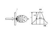
本発明においては、輝度特性、視認性および品位等のバランスを考慮して光偏向素子4からの出射光を適度に拡散させる光拡散特性を有する光拡散素子6を使用することが必要である。すなわち、光拡散素子6の光拡散性が低い場合には、視野角を十分に広げることが困難となり視認性を低下させるとともに、品位改善効果が十分でなくなる傾向にあり、逆に光拡散性が高すぎる場合には光偏向素子4による狭視野化の効果が損なわれるとともに、全光線透過率も低くなり輝度が低下する傾向にある。そこで、本発明の光拡散素子6においては、平行光を入射したときの出射光光度分布の半値全幅が1〜13度の範囲であるものが使用される。光拡散素子6の半値全幅は、好ましくは3〜11度の範囲、さらに好ましくは4〜8.5度の範囲である。なお、本発明において光拡散素子6の出射光光度分布の半値全幅とは、図3に示すように、光拡散素子6に入射した平行光線が出射時にどの程度拡散して広がるかを示したもので、光拡散素子6を透過拡散した出射光の光度光度分布におけるピ−ク値に対する半値での広がり角の全幅の角度(ΔθH)をいう。
【0048】
このような光拡散特性は、光拡散素子6中に光拡散剤を混入したり、光拡散素子6の少なくとも一方の表面に凹凸構造を付与することによって付与することができる。表面に形成する凹凸構造は、光拡散素子6の一方の表面に形成する場合と両方の表面に形成する場合とでは、その程度が異なる。光拡散素子6の一方の表面に凹凸構造を形成する場合には、その平均傾斜角を0.8〜12度の範囲とすることが好ましく、さらに好ましくは3.5〜7度であり、より好ましくは4〜6.5度である。光拡散素子6の両方の表面に凹凸構造を形成する場合には、一方の表面に形成する凹凸構造の平均傾斜角を0.8〜6度の範囲とすることが好ましく、さらに好ましくは2〜4度であり、より好ましくは2.5〜4度である。この場合、光拡散素子6の全光線透過率の低下を抑止するためには、光拡散素子6の入射面側の平均傾斜角を出射面側の平均傾斜角よりも大きくすることが好ましい。また、光拡散素子6のヘイズ値としては8〜82%の範囲とすることが、輝度特性向上と視認性改良の観点から好ましく、さらに好ましくは30〜70%の範囲であり、より好ましくは40〜65%の範囲である。
【0049】
本発明の光源装置においては、その発光面(光拡散素子6の出射面)の法線方向から観察した場合の表示エリア(即ち光源装置と組み合わせて使用される液晶表示素子等の表示素子の有効表示エリアに対応する有効発光領域)内における輝度が均一であることも要求される。この輝度の均一性は光源の表示エリアの大きさにも依存し、例えば、ノートパソコンやモニター等の表示エリアが大きい大型の光源装置では、比較的広い視野角特性が要求される場合があり、発光面からの出射する出射光輝度分布(XZ面内)をより広くすることが要求される。一方、携帯電話や携帯情報端末等の表示エリアが小さい小型の光源装置では、高輝度や表示品位向上が優先される場合があり、発光面からの出射する出射光輝度分布(XZ面内)は比較的狭くてもよい。このため、光拡散素子6としては、光源装置の表示エリアの大きさに応じて適切な光拡散特性を有するものを使用することが好ましい。
【0050】
このような光源装置の表示エリアの大きさに応じた光拡散素子6の光拡散特性について、説明する。なお、光源装置の表示エリアの大きさは、その展開長を基準として説明する。ここで、光源装置の展開長(導光体3の展開長)とは、図4に示したように、線状の冷陰極光源が一次光源1として導光体3の光入射面に配置された場合、導光体3に入射した光が導光する方向、すなわち光入射面と垂直な方向における表示エリアの最長距離Lをいう。また、図5に示したように、導光体3のコ−ナにLED等の点光源が一次光源1として配置された場合、光点源から最も遠い有効表示エリアと点光源を結ぶ直線上の表示エリアの距離Lをいう。
【0051】
(1)導光体3の展開長が8cm以下の場合
このような光源装置は、一次光源1として線状の冷陰極管(一灯型)やLED等が使用され、携帯電話、携帯情報端末、デジタルカメラ等の表示エリアが小さい表示装置に使用されるため、視野角をさほど大きくする必要はなく、品位低下の原因となるぎらつきや輝度斑等を抑える程度の光拡散性を光拡散素子6により付与し、光利用効率を高め高輝度を維持するとともに、消費電力を低く抑えることが必要となる。このため、光拡散素子6としては、出射光光度分布の半値全幅が1〜6度の範囲であることが好ましく、さらに好ましくは1〜5度、より好ましくは2〜5度の範囲である。また、ヘイズ値としては、8〜60%の範囲であることが好ましく、さらに好ましくは8〜50%、より好ましくは20〜50%の範囲である。さらに、光拡散素子6の表面に凹凸構造を形成する場合には、その平均傾斜角が0.8〜5度の範囲であることが好ましく、さらに好ましくは0.8〜4度、より好ましくは2〜4度の範囲である。
【0052】
(2)導光体3の展開長が8cmを超え23cm以下の場合(一次光源1として一灯型の冷陰極管を使用)
このような光源装置は、ノートパソコン、デスクトップ型パソコンのモニター、比較的小型の液晶テレビ等の表示装置に使用されるため、比較的広い視野角が必要であり、液晶表示装置の高解像度化に伴い品位の高い高輝度が必要となる。このため、光拡散素子6としては、出射光光度分布の半値全幅が3〜11度の範囲であることが好ましく、さらに好ましくは4〜10度、より好ましくは4〜9度の範囲である。また、ヘイズ値としては、30〜80%の範囲であることが好ましく、さらに好ましくは40〜73%、より好ましくは45〜70%の範囲である。さらに、光拡散素子6の表面に凹凸構造を形成する場合には、その平均傾斜角が3〜9.5度の範囲であることが好ましく、さらに好ましくは3.5〜8.5度、より好ましくは4.5〜7度の範囲である。
【0053】
導光体3の展開長が8cmを超え18cm以下の場合には、比較的小型のノートパソコンの表示装置に使用されるため、必要な視野角はやや狭いものである。このため、光拡散素子6としては、出射光光度分布の半値全幅が3〜8度の範囲であることが好ましく、さらに好ましくは4〜8度、より好ましくは4〜7度の範囲である。また、ヘイズ値としては、30〜70%の範囲であることが好ましく、さらに好ましくは40〜65%、より好ましくは45〜60%の範囲である。さらに、光拡散素子6の表面に凹凸構造を形成する場合には、その平均傾斜角が3〜7度の範囲であることが好ましく、さらに好ましくは3.5〜6.5度、より好ましくは4.5〜6度の範囲である。
【0054】
導光体3の展開長が18cmを超え22cm以下の場合には、比較的大形のノートパソコンの表示装置に使用されるため、比較的広い視野角が必要であるとともに、表示エリア内での輝度の均一性を達成することが必要である。このため、光拡散素子6としては、出射光光度分布の半値全幅が4〜10度の範囲であることが好ましく、さらに好ましくは5〜9度、より好ましくは5〜8.5度の範囲である。また、ヘイズ値としては、40〜75%の範囲であることが好ましく、さらに好ましくは50〜70%、より好ましくは50〜65%の範囲である。さらに、光拡散素子6の表面に凹凸構造を形成する場合には、その平均傾斜角が3.5〜8度の範囲であることが好ましく、さらに好ましくは4〜7度、より好ましくは4.5〜6.5度の範囲である。
【0055】
導光体3の展開長が22cmを超え23cm以下の場合は、比較的大型のノートパソコン等の表示装置に使用される。一灯型の冷陰極管を一次光源1として使用するノートパソコンとしては表示エリアが大きいものであり、導光体3の展開長が22cm以下のものと比較すると、光利用効率をより高くし輝度を向上させることが必要となる。このように輝度をより高くしようとすると、例えば、光源装置の導光体3の裏面に配置される反射シートとして、指向性反射性の低い発泡PET反射フィルムに代えて指向性反射特性に優れる銀反射シ−トやアルミ反射シ−ト等の金属反射シートを使用する必要がある。しかし、金属反射シ−トを使用した場合には、金属反射特有のぎらつき、入射面近傍に現れる暗線輝線、入射面両端部近傍に現れる暗部等の欠陥が強く発現され、光源装置としての品位が損なわれる傾向にある。このような品位低下を抑止するためには、出射光光度分布の半値全幅が9度を超えるような光拡散性の高い光拡散素子6を使用することが必要となってくるが、このうような光拡散素子6を使用した場合には光拡散性が大きくなりすぎるとともに、全光線透過率の大幅な低下を招くため、十分に高い輝度が得られないという問題点を有する。このため、このような品位低下を導光体3や光偏向素子4にて抑止し、光拡散素子6としては、出射光光度分布の半値全幅が5〜11度の範囲のものを使用することが好ましく、さらに好ましくは6〜10度、より好ましくは7〜9度の範囲である。また、ヘイズ値としては、50〜80%の範囲であることが好ましく、さらに好ましくは55〜73%、より好ましくは55〜70%の範囲である。さらに、光拡散素子6の表面に凹凸構造を形成する場合には、その平均傾斜角が4.5〜9.5度の範囲であることが好ましく、さらに好ましくは5〜8.5度、より好ましくは5〜7度の範囲である。
【0056】
(3)導光体3の展開長が8cmを超え28cm以下の場合(一次光源1として多灯型の冷陰極管を使用)
このような光源装置は、デスクトップ型パソコンのモニター、液晶テレビ等の表示装置に使用されるため、比較的広い視野角が必要であるとともに高い輝度が必要となる。このため、一次光源1としては導光体3の対向する2つの端面にそれぞれ1個以上の冷陰極管を配置した多灯型のものが使用される。このような光源装置では、一灯型の一次光源1を用いたものとは品位に関する視認性が異なり、後述するような出射光輝度分布(XZ面内)の非対称性はその特性を失い、光源装置の中央部付近の出射光輝度分布(XZ面内)は、図6に示したように、光拡散素子6を使用しない場合でも対称性が向上する。さらに、光源に近い両端部近傍での出射光輝度分布(XZ面内)は、それぞれ最も近いところから導光される光の影響をうけ、若干非対称性を帯びた出射光輝度分布(XZ面内)となる。すなわち、図6の左側の端部近傍では、光源側の出射光輝度分布(XZ面内)が急峻で、中央側の出射光輝度分布(XZ面内)は滑らかなテイリング傾向を有しているため、左端部近傍での光の出射方向はやや中央部へ向いている成分が多くなっている。一方、図6の右側の端部近傍では、これと反対の出射光輝度分布(XZ面内)を有しており、光の出射方向はやや中央部へ向いている成分が多くなっている。このため、中央部から両端部近傍を観察したときの視認性に優れた出射光特性が得られ、端部まで高品位な、高い輝度を有する光源装置となる。
【0057】
このため、光拡散素子6としては、広い視野角を得る光拡散性が必要とされ、出射光光度分布の半値全幅が0.7〜13度の範囲のものを使用することが好ましく、さらに好ましくは1〜11度、より好ましくは2〜9度の範囲である。また、ヘイズ値としては、30〜82%の範囲であることが好ましく、さらに好ましくは35〜75%、より好ましくは40〜70%の範囲である。さらに、光拡散素子6の表面に凹凸構造を形成する場合には、その平均傾斜角が0.8〜12度の範囲であることが好ましく、さらに好ましくは1〜8.5度、より好ましくは1.5〜7度の範囲である。また、導光体3の展開長が22cmを超え28cm以下である場合には、光拡散素子6としては、出射光光度分布の半値全幅が6〜13度の範囲のものを使用することが好ましく、さらに好ましくは7〜11度、より好ましくは7〜9度の範囲である。また、ヘイズ値としては、50〜82%の範囲であることが好ましく、さらに好ましくは60〜75%、より好ましくは65〜70%の範囲である。さらに、光拡散素子6の表面に凹凸構造を形成する場合には、その平均傾斜角が4.5〜12度の範囲であることが好ましく、さらに好ましくは5.5〜8.5度、より好ましくは6〜7度の範囲である。さらに、導光体3の展開長が8cmを超え22cm以下である場合には、光拡散素子6としては、出射光光度分布の半値全幅が0.7〜6度の範囲のものを使用することが好ましく、さらに好ましくは1〜5度、より好ましくは2〜4度の範囲である。また、ヘイズ値としては、30〜60%の範囲であることが好ましく、さらに好ましくは35〜55%、より好ましくは40〜50%の範囲である。さらに、光拡散素子6の表面に凹凸構造を形成する場合には、その平均傾斜角が0.8〜6度の範囲であることが好ましく、さらに好ましくは1〜5度、より好ましくは1.5〜4.5度の範囲である。
【0058】
本発明の光源装置においては、上記のような光拡散素子6を用いる場合、光偏向素子4からの出射光輝度分布(XZ面内)の半値全幅が19〜26度程度の集光性が比較的弱い光偏向素子4を使用するとともに、光拡散性の比較的弱い光拡散素子6を使用した方がYZ面での拡散による輝度の低下を抑えられるため、輝度向上の観点からは好ましい場合がある。この場合、光拡散素子6としては、広い視野角を得る光拡散性が必要とされ、出射光光度分布の半値全幅が1〜8度の範囲のものを使用することが好ましく、さらに好ましくは2〜8度、より好ましくは3〜7度の範囲である。また、ヘイズ値としては、8〜70%の範囲であることが好ましく、さらに好ましくは30〜65%、より好ましくは40〜60%の範囲である。さらに、光拡散素子6の一方の表面に凹凸構造を形成する場合には、その平均傾斜角が0.8〜7度の範囲であることが好ましく、さらに好ましくは3〜6.5度、より好ましくは3.5〜6度の範囲である。凹凸構造を両面に形成する場合には、その一方の表面の平均傾斜角が0.8〜4度の範囲であることが好ましく、さらに好ましくは1〜4度、より好ましくは2〜4度の範囲である。
【0059】
本発明の光源装置においては、光偏向素子4の出光面から出射する出射光は図7に示したような非対称的な出射光輝度分布(XZ面内:光拡散素子なし)を有する場合がある。この出射光輝度分布(XZ面内)は、導光体3から出射した出射光光度分布(XZ面内)に由来するものである。このような非対称的な出射光輝度分布(XZ面内)は、例えば、光偏向素子4からの出射光輝度分布(XZ面内)の半値全幅が、20度以下の指向性の高い出射光が出射される場合に発現する傾向にある。特に、表示エリアの比較的大きな光源装置においては、このような出射光輝度分布(XZ面内)の非対称性を緩和させるためには、光拡散性の比較的強い光拡散素子6を使用することが必要となる(図7にこのような光拡散素子を使用した場合の出射光輝度分布を示した(光拡散素子あり)。)。一方、光拡散素子6として、出射光光度分布の半値全幅が4度以上、ヘイズ値が35%以上のものを使用した場合には、光拡散素子6から出射する出射光輝度分布(XZ面内)のピーク角度が光偏向素子4からの出射光輝度分布(XZ面内)のピーク角度に対して、光源と反対側の方向へ1〜3度程度偏角される。このため、光偏角素子からの出射光輝度分布(XZ面内)のピーク角度が所望の方向(例えば法線方向)にある場合には、光拡散素子6を使用することによって所望の方向での輝度の低下を招くことになる。従って、光偏向素子4からの出射光輝度分布(XZ面内)の半値全幅が20度以下である場合に上記のような光拡散素子6を使用する際には、図7に示したように、予め、光偏向素子4からの出射光輝度分布(XZ面内)のピーク角度が所望の方向から光源側に0.5〜3度、さらに好ましくは0.5〜2度、より好ましくは1〜2度傾くように光偏向素子4等を設計しておくことが好ましい。
【0060】
本発明においては、光拡散素子6として光拡散性に異方性を有するものを使用することが、光拡散素子6の全光線透過率を高め、光偏向素子4からの出射光を効率的に拡散でき、輝度を向上させることができるため好ましい。例えば、導光体3の一つの端面に線上の冷陰極管を一次光源1として配置した光源装置においては、狭視野化を図る光偏向素子4では、導光体3の光出射面から出射する出射光をXZ面において主として狭視野化を図るものであり、さらに光拡散素子6により狭視野化されたXZ面の光を主として拡散させ視野角を広げることを目的としている。しかし、光拡散素子6として等方性拡散性のものを使用した場合には、光偏角素子により狭視野化されていないYZ面の光も同等に拡散されるため、輝度の低下を招くことになる。そこで、図8に示したように、YZ面よりもXZ面での光拡散性が高いような異方拡散性を有する光拡散素子6を使用することにより、光偏向素子4により狭視野化されたXZ面の光を強く拡散し、狭視野化されていないYZ面の光の拡散を弱くすることができ、光偏向素子4からの出射光を効率的に拡散することができ、輝度の低下をできる限り最小に抑えることができる。
【0061】
本発明においては、このような光拡散素子6の異方拡散性については、どのような異方性を有する光拡散素子6を使用するかは、上記のようにXZ面とYZ面での異方性に限定されるものではなく、導光体3の光出射機構、光偏向素子4のレンズ形状や配列、光源装置の用途等に応じて適宜選定することができる。すなわち、図9に示したように、光拡散素子6の出射面に対する法線軸を含む任意の面(ZP-n面(n=1,2,・・・・))を想定し、これらの任意の面における出射光輝度分布(XZ面内)の半値全幅を相違させることによって異方性を付与することができる。なお、ZP-n面の中で最も大きい半値全幅を最大半値全幅、最も小さい半値全幅を最小半値全幅とする。同様に、光拡散素子6に異方拡散性を付与する凹凸構造の平均傾斜角についても、ZP-n面と光拡散素子6(XY面)が交差する任意のP-n方向における平均傾斜角を相違させることによって平均傾斜角の異方性を付与することができる。このとき、P-n方向の中で最も大きい平均傾斜角を最大平均傾斜角、最も小さい平均傾斜角を最小平均傾斜角とする。
【0062】
例えば、導光体3の一つの端面に線上の冷陰極管を配置し一次光源1とした場合、光偏向素子4は主としてXZ面で狭視野化を主として図り、YZ面では殆ど作用しないため、XZ面で効果的に出射光を拡散し、YZ面では出射光を拡散させないような異方拡散性を有する光拡散素子6を使用することが最適である。従って、光拡散素子6としては、XZ面で最大半値全幅を示し、YZ面で最小半値全幅を示すような異方拡散性を有するものが好ましい。同様に、光拡散素子6に形成する凹凸構造も、X方向に最大平均傾斜角を有し、Y方向に最小平均傾斜角を有するような構造あるいは配置とすることが好ましい。
【0063】
このような異方拡散性を有する光拡散素子6においても、輝度特性、視認性および品位等のバランスを考慮して光偏向素子4からの出射光を適度に拡散させる光拡散特性を有する光拡散素子6を使用することが必要である。すなわち、光拡散素子6の光拡散性が低い場合には、視野角を十分に広げることが困難となり視認性を低下させるとともに、品位改善効果が十分でなくなる傾向にあり、逆に光拡散性が高すぎる場合には光偏向素子4による狭視野化の効果が損なわれるとともに、全光線透過率も低くなり輝度が低下する傾向にある。そこで、出射光光度分布の最大半値全幅が1〜13度の範囲であるものが使用され、好ましくは3〜11度の範囲、さらに好ましくは4〜9度の範囲である。また、最小半値全幅に対する最大半値全幅の比(最大半値全幅/最小半値全幅)が1.1〜20の範囲であることが好ましく、さらに好ましくは2〜15の範囲、より好ましくは4〜10の範囲である。これは、最大半値全幅/最小半値全幅を1.1以上とすることによって光の利用効率を向上させ輝度を高めることができるためであり、20以下とすることによって強い光拡散性による輝度の低下を抑止することができるためである。
【0064】
光拡散素子6の一方の表面に凹凸構造を形成する場合には、その最大平均傾斜角を0.8〜15度の範囲とすることが好ましく、さらに好ましくは3.5〜11度であり、より好ましくは4〜9度である。また、最大半値全幅/最小半値全幅と同様の観点から、最小平均傾斜角に対する最大平均傾斜角の比(最大平均傾斜角/最小平均傾斜角)は、1.1〜20の範囲であることが好ましく、さらに好ましくは2〜15の範囲、より好ましくは4〜10の範囲である。凹凸構造は、光拡散素子6の両方の表面に形成してもよく、この場合、光拡散素子6の全光線透過率の低下を抑止するためには、光拡散素子6の入射面側の平均傾斜角を出射面側の平均傾斜角よりも大きくすることが好ましい。また、光拡散素子6のヘイズ値としては8〜82%の範囲とすることが、輝度特性向上と視認性改良の観点から好ましく、さらに好ましくは30〜70%の範囲であり、より好ましくは40〜65%の範囲である。
【0065】
また、光拡散素子6としては、光源装置の表示エリアの大きさに応じて適切な光拡散特性を有するものを使用することが好ましい。導光体3の展開長が8cm以下の場合には、光拡散素子6としては、出射光光度分布の最大半値全幅が1〜6度の範囲であることが好ましく、さらに好ましくは1〜5度、より好ましくは2〜5度の範囲である。また、ヘイズ値としては、8〜60%の範囲であることが好ましく、さらに好ましくは8〜50%、より好ましくは20〜50%の範囲である。さらに、光拡散素子6の表面に凹凸構造を形成する場合には、その最大平均傾斜角が0.8〜5度の範囲であることが好ましく、さらに好ましくは0.8〜4度、より好ましくは2〜4度の範囲である。
【0066】
導光体3の展開長が8cmを超え23cm以下の場合(一次光源1として一灯型の冷陰極管を使用)には、光拡散素子6としては、出射光光度分布の最大半値全幅が3〜13度の範囲であることが好ましく、さらに好ましくは4〜10度、より好ましくは4〜9度の範囲である。また、ヘイズ値としては、30〜80%の範囲であることが好ましく、さらに好ましくは40〜73%、より好ましくは45〜70%の範囲である。さらに、光拡散素子6の表面に凹凸構造を形成する場合には、その最大平均傾斜角が3〜15度の範囲であることが好ましく、さらに好ましくは3.5〜10度、より好ましくは4.5〜8度の範囲である。
【0067】
導光体3の展開長が8cmを超え18cm以下の場合には、光拡散素子6としては、出射光光度分布の最大半値全幅が3〜10度の範囲であることが好ましく、さらに好ましくは4〜10度、より好ましくは4〜9度の範囲である。また、ヘイズ値としては、30〜70%の範囲であることが好ましく、さらに好ましくは40〜65%、より好ましくは45〜60%の範囲である。さらに、光拡散素子6の表面に凹凸構造を形成する場合には、その最大平均傾斜角が3〜9度の範囲であることが好ましく、さらに好ましくは3.5〜8度、より好ましくは4.5〜8度の範囲である。
【0068】
導光体3の展開長が18cmを超え22cm以下の場合には、光拡散素子6としては、出射光光度分布の最大半値全幅が4〜13度の範囲であることが好ましく、さらに好ましくは5〜11度、より好ましくは5〜8.5度の範囲である。また、ヘイズ値としては、40〜75%の範囲であることが好ましく、さらに好ましくは50〜70%、より好ましくは50〜65%の範囲である。さらに、光拡散素子6の表面に凹凸構造を形成する場合には、その最大平均傾斜角が3.5〜15度の範囲であることが好ましく、さらに好ましくは4〜9度、より好ましくは4.5〜6.5度の範囲である。
【0069】
導光体3の展開長が22cmを超え23cm以下の場合は、光拡散素子6としては、出射光光度分布の最大半値全幅が5〜13度の範囲のものを使用することが好ましく、さらに好ましくは6〜12度、より好ましくは7〜9度の範囲である。また、ヘイズ値としては、50〜80%の範囲であることが好ましく、さらに好ましくは55〜73%、より好ましくは55〜70%の範囲である。さらに、光拡散素子6の表面に凹凸構造を形成する場合には、その最大平均傾斜角が4.5〜15度の範囲であることが好ましく、さらに好ましくは5〜10度、より好ましくは5〜7度の範囲である。
【0070】
導光体3の展開長が8cmを超え28cm以下の場合(一次光源1として多灯型の連陰極管を使用)には、光拡散素子6としては、広い視野角を得る光拡散性が必要とされ、出射光光度分布の最大半値全幅が0.7〜13度の範囲のものを使用することが好ましく、さらに好ましくは1〜11度、より好ましくは2〜9度の範囲である。また、ヘイズ値としては、30〜82%の範囲であることが好ましく、さらに好ましくは35〜75%、より好ましくは40〜70%の範囲である。さらに、光拡散素子6の表面に凹凸構造を形成する場合には、その最大平均傾斜角が0.8〜15度の範囲であることが好ましく、さらに好ましくは1〜13度、より好ましくは1.5〜7度の範囲である。また、導光体3の展開長が22cmを超え28cm以下である場合には、光拡散素子6としては、出射光光度分布の半値全幅が6〜13度の範囲のものを使用することが好ましく、さらに好ましくは7〜11度、より好ましくは7〜9度の範囲である。また、ヘイズ値としては、50〜82%の範囲であることが好ましく、さらに好ましくは60〜75%、より好ましくは65〜70%の範囲である。さらに、光拡散素子6の表面に凹凸構造を形成する場合には、その平均傾斜角が4.5〜15度の範囲であることが好ましく、さらに好ましくは5.5〜13度、より好ましくは6〜7度の範囲である。さらに、導光体3の展開長が8cmを超え22cm以下である場合には、光拡散素子6としては、出射光光度分布の半値全幅が0.7〜6度の範囲のものを使用することが好ましく、さらに好ましくは1〜5度、より好ましくは2〜4度の範囲である。また、ヘイズ値としては、30〜60%の範囲であることが好ましく、さらに好ましくは35〜55%、より好ましくは40〜50%の範囲である。さらに、光拡散素子6の表面に凹凸構造を形成する場合には、その平均傾斜角が0.8〜10度の範囲であることが好ましく、さらに好ましくは1〜7度、より好ましくは1.5〜5度の範囲である。
【0071】
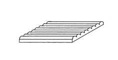
このような異方拡散性を有する光拡散素子6の拡散性付与構造としては、例えば、図10〜12に示したような凹凸構造が挙げられる。図10に示した凹凸構造は、一軸上に長く伸びたレンチキュラーレンズ列等のレンズ列を多数並列して連設した配列構造である。このようなレンズ列の配列ピッチは表示装置として使用される液晶素子のピッチおよび光偏向素子4のプリズム列等のレンズ列の配列ピッチに対してモアレの発生しにくいピッチを選定するか、ランダムな配列ピッチとすることが好まし。通常、レンズ列の配列ピッチは1〜70μmの範囲とすることが好ましく、製造の容易さやモアレの発生を防止する観点から5〜40μmがさらに好ましく、より好ましくは10〜30μmの範囲である。また、レンズ列の長手方向と直交する方向の平均傾斜角は0.8〜15度の範囲とすることが輝度向上と視認性の観点から好ましく、さらに好ましくは3.5〜11度、より好ましくは4〜9度の範囲である。
【0072】
図11に示した凹凸構造は、多数のシリンドリカルレンズ形状体を離散的に配列した構造である。シリンドリカルレンズ形状体の配列間隔は、一定の規則的なピッチでもよく、ランダムな配列ピッチであってもよい。通常、シリンドリカルレンズ形状体の配列ピッチは、1〜70μmの範囲とすることが好ましく、製造の容易さやモアレの発生を防止する観点から5〜40μmがさらに好ましく、より好ましくは10〜30μmの範囲である。また、シリンドリカルレンズ形状体の長手方向と直交する方向の平均傾斜角は0.8〜15度とすることが輝度向上と視認性の観点から好ましく、さらに好ましくは3.5〜11度、より好ましくは4〜9度の範囲である。このような離散的な配列構造は、光拡散素子6として最大半値全幅であることが必要な面と光拡散素子6の出射面との交差する線と、シリンドリカルレンズ形状体の長手方向が略直交する確率ができるだけ高くなるように配列することが好ましい。また、光拡散素子6として最小半値全幅であることが必要な面と光拡散素子6の出射面と交差する線と、シリンドリカルレンズ形状体の長手方向が略平行になる確率ができるだけ高くなるよう配列することが好ましい。
【0073】
図12に示した凹凸構造はヘアライン構造である。ヘアラインの延びる方向に直交方向の平均傾斜角は0.8〜15度とすることが輝度向上と視認性の観点から好ましく、さらに好ましくは3.5〜11度、より好ましくは4〜9度の範囲である。ヘアラインの延びる方向は、光拡散素子6として最大半値全幅であることが必要な面と光拡散素子6の出射面との交差する線と略直交する方向が好ましい。
【0074】
このような異方拡散性を付与する凹凸構造が形成された面およびその裏面の少なくとも一方にマット構造を付与することにより、ぎらつきや輝度斑等を抑止することができ品位を向上させることができる。しかし、マット構造の光拡散性が強くなると異方拡散性が損なわれ輝度の低下を招く場合があるため、比較的光拡散性の弱いマット構造を付与することが好ましい。このようなマット構造としては、平均傾斜角度が0.5〜5度の範囲のものが好ましく、さらに好ましくは0.8〜4度、より好ましくは1〜3.5度の範囲である。なお、異方性付与凹凸構造の表面にマット構造を付与した場合のマット構造の平均傾斜角は、凹凸構造に起因する平均傾斜角度を除いたマット構造自体の平均傾斜角をいう。すなわち、凹凸構造の無い部分や凹凸構造の長手方向に平行な平均傾斜角を測定することができ、触針粗さ計による計測、光拡散素子6の断面形状を画像解析する方法、原子間力顕微鏡等によって測定することができる。
【0075】
本発明においては、光偏向素子4を用いて導光体3からの出射光を法線方向等の特定な方向に出射させ、この出射光を異方拡散性を有する光拡散素子6を用いて所望の方向に出射させることもできる。この場合、光拡散素子6に異方拡散作用と光偏向角作用の両方の機能を付与することもできる。例えば、凹凸構造としてレンチキュラーレンズ列やシリンドリカルレンズ形状体を用いたものでは、その断面形状を非対称形状にすることで、異方拡散作用と光偏向作用の両機能を付与することができる。
【0076】
また、本発明においては、光源装置としての視野角を調整し、品位を向上させる目的で、光偏向素子4や光拡散素子6に光拡散材を含有させることもできる。このような光拡散材としては、光偏向素子4や光拡散素子6を構成する材料と屈折率が異なる透明な微粒子を使用することができ、例えば、シリコンビーズ、ポリスチレン、ポリメチルメタクリレ−ト、フッ素化メタクリレ−ト等の単独重合体あるいは共重合体等が挙げられる。光拡散材としては、光偏向素子4による狭視野効果や光拡散素子6による適度な拡散効果を損なわないように、含有量、粒径、屈折率等を適宜選定する必要がある。例えば、光拡散材の屈折率は、光偏向素子4や光拡散素子6を構成する材料との屈折率差が小さすぎると拡散効果が小さく、大きすぎると過剰な散乱屈折作用が生じるため、屈折率差が0.01〜0.1の範囲とすることが好ましく、さらに好ましくは0.03〜0.08、より好ましくは0.03〜0.05の範囲である。また、拡散材の粒径は、粒径が大きすぎると散乱が強くなりぎらつきや輝度の低下を引き起こし、小さすぎると着色が発生するため、平均粒径が0.5〜20μmの範囲とすることが好ましく、さらに好ましくは2〜15μm、より好ましくは2〜10μmの範囲である。
【0077】
一次光源1はY方向に延在する線状の光源であり、該一次光源1としては例えば蛍光ランプや冷陰極管を用いることができる。なお、本発明においては、一次光源1としては線状光源に限定されるものではなく、LED光源、ハロゲンランプ、メタハロランプ等のような点光源を使用することもできる。特に、携帯電話機や携帯情報端末機等の比較的小さな画面寸法の表示装置に使用する場合には、LED等の小さな点光源を使用することが好ましい。また、一次光源1は、図1に示したように、導光体3の一方の側端面に設置する場合だけでなく、必要に応じて対向する他方の側端面にもさらに設置することもできる。
【0078】
光源リフレクタ2は一次光源1の光をロスを少なく導光体3へ導くものである。材質としては、例えば表面に金属蒸着反射層有するプラスチックフィルムを用いることができる。図示されているように、光源リフレクタ2は、光反射素子5の端縁部外面から一次光源1の外面を経て光偏向素子4の出光面端縁部へと巻きつけられている。他方、光源リフレクタ2は、光偏向素子4を避けて、光反射素子5の端縁部外面から一次光源1の外面を経て導光体3の光出射面端縁部へと巻きつけることも可能である。
【0079】
このような光源リフレクタ2と同様な反射部材を、導光体3の側端面31以外の側端面に付することも可能である。光反射素子5としては、例えば表面に金属蒸着反射層を有するプラスチックシートを用いることができる。本発明においては、光反射素子5として反射シートに代えて、導光体3の裏面34に金属蒸着等により形成された光反射層等とすることも可能である。
【0080】
本発明の導光体3、光偏向素子4および光拡散素子6は、光透過率の高い合成樹脂から構成することができる。このような合成樹脂としては、メタクリル樹脂、アクリル樹脂、ポリカーボネート系樹脂、ポリエステル系樹脂、塩化ビニル系樹脂が例示できる。特に、メタクリル樹脂が、光透過率の高さ、耐熱性、力学的特性、成形加工性に優れており、最適である。このようなメタクリル樹脂としては、メタクリル酸メチルを主成分とする樹脂であり、メタクリル酸メチルが80重量%以上であるものが好ましい。導光体3及び光偏向素子4の粗面の表面構造やプリズム列等の表面構造を形成するに際しては、透明合成樹脂板を所望の表面構造を有する型部材を用いて熱プレスすることで形成してもよいし、スクリーン印刷、押出成形や射出成形等によって成形と同時に形状付与してもよい。また、熱あるいは光硬化性樹脂等を用いて構造面を形成することもできる。更に、ポリエステル系樹脂、アクリル系樹脂、ポリカーボネート系樹脂、塩化ビニル系樹脂、ポリメタクリルイミド系樹脂等からなる透明フィルムあるいはシート等の透明基材上に、活性エネルギー線硬化型樹脂からなる粗面構造またレンズ列配列構造を表面に形成してもよいし、このようなシートを接着、融着等の方法によって別個の透明基材上に接合一体化させてもよい。活性エネルギー線硬化型樹脂としては、多官能(メタ)アクリル化合物、ビニル化合物、(メタ)アクリル酸エステル類、アリル化合物、(メタ)アクリル酸の金属塩等を使用することができる。
【0081】
以上のような一次光源1、光源リフレクタ2、導光体3、光偏向素子4、光拡散素子6および光反射素子5からなる光源装置の発光面(光拡散素子6の出光面)上に、液晶表示素子を配置することにより、本発明の光源装置をバックライトとした液晶表示装置が構成される。液晶表示装置は、図1における上方から液晶表示素子を通して観察者により観察される。また、本発明においては、十分にコリメートされた狭い輝度分布(XZ面内)の光を光源装置から液晶表示素子に入射させることができるため、液晶表示素子での階調反転等がなく明るさ、色相の均一性の良好な画像表示が得られるとともに、所望の方向に集中した光照射が得られ、この方向の照明に対する一次光源1の発光光量の利用効率を高めることができる。
【0082】
尚、以上の実施形態は光源装置に関して説明したが、本発明はY方向寸法が例えば導光体3の厚さの5倍以下であるX方向に細長い棒状の光源装置にも適用できる。その場合、一次光源1としてはLED等の略点状のものを使用することができる。
【0083】
【実施例】
以下、実施例によって本発明を具体的に説明する。
なお、以下の実施例における各物性の測定は下記のようにして行った。
【0084】
面光源装置の法線輝度、光度半値全幅の測定
光源として冷陰極管を用い、インバータ(ハリソン社製HIU−742A)にDC12Vを印加して高周波点灯させた。輝度は、面光源装置あるいは導光体の表面を20mm四方の正方形に3×5分割し、各正方形の法線方向の輝度値の15点平均を求めた。導光体の光度半値全幅は、導光体の表面に4mmφのピンホールを有する黒色の紙をピンホールが表面の中央に位置するように固定し、輝度計の測定円が8〜9mmとなるように距離を調整し、冷陰極管の長手方向軸と垂直方向および平行方向でピンホールを中心にゴニオ回転軸が回転するように調節した。それぞれの方向で回転軸を+80度〜−80度まで1度間隔で回転させながら、輝度計で出射光の光度分布(XZ面内)を測定し、ピーク角度、半値全幅(ピーク値の1/2の分布(XZ面内)の広がり角)を求めた。また、面光源装置の輝度半値全幅は、輝度計の視野角度を0.1度にし、面光源装置の中央の面に位置するよう調整し、ゴニオ回転軸が回転するように調節した。それぞれの方向で回転軸を+80度〜−80度まで1度間隔で回転させながら、輝度計で出射光の輝度分布(XZ面内)を測定し、ピーク輝度、半値全幅(ピーク値の1/2の分布(XZ面内)の広がり角)を求めた。
【0085】
平均傾斜角(θa)の測定
ISO4287/1−1987に従って、触針として010−2528(1μmR、55度円錐、ダイヤモンド)を用いた触針式表面粗さ計(東京精器(株)製サーフコム570A)にて、粗面の表面粗さを駆動速度0.03mm/秒で測定した。この測定により得られたチャートより、その平均線を差し引いて傾斜を補正し、前記式(1)式および(2)式によって計算して求めた。
【0086】
ヘイズ値の測定
ヘイズ値は、JIS K−7105のB法に従って、50mm×50mmの大きさの試料を積分球式反射透過率計(村上色彩技術研究社製RT−100型)を用いて得られた全光線透過率(Tt)、拡散光線透過率(Td)から、次の式(6)によって計算して求めた。
【0087】
【数5】
光拡散分布角度は、50mm×50mmの大きさの試料を自動変角光度計(村上色彩研究所社製GP−200型)を用いて測定し、求めたピーク光度の1/2光度である半値半幅角度の2倍をサンプルの半値全幅角度(α)とした。なお、試料に入射させる光は、光源からの光をコンデンサーレンズによりピンホールに集光し、コリメーターレンズを通して平行光(平行度±0.5度以下)とし、光束絞り(開口径10.5mm)を通過し試料の入射面に入射させる。試料を透過した光は、受光レンズ(開口径11.4mmを通り(試料面が平滑である場合は、受光絞りの位置に集光する)、受光絞りを通過して受光素子に達し、電圧値として出力する。また、試料を回転させ同様の測定を行い、最大半値全幅(Maxα)と最小半値全幅(Minα)を求めた。
【0088】
実施例1
アクリル樹脂(三菱レイヨン(株)製アクリペットVH5#000)を用い射出成形することによって一方の面がマットである導光体を作製した。該導光体は、216mm×290mm、厚さ2.0mm−0.7mmのクサビ板状をなしていた。この導光体の鏡面側に、導光体の長さ216mmの辺(短辺)と平行になるように、アクリル系紫外線硬化樹脂によってプリズム列のプリズム頂角130度、ピッチ50μmのプリズム列が並列に連設配列されたプリズム層を形成した。導光体の長さ290mmの辺(長辺)に対応する一方の側端面(厚さ2.0mmの側の端面)に対向するようにして、長辺に沿って冷陰極管を光源リフレクター(麗光社製銀反射フィルム)で覆い配置した。さらに、その他の側端面に光拡散反射フィルム(東レ社製E60)を貼付し、プリズム列配列(裏面)に反射シートを配置した。以上の構成を枠体に組み込んだ。この導光体は、出射光光度分布(XZ面内)の最大ピークは光出射面法線方向に対して70度、半値全幅は22.5度であった。
【0089】
一方、屈折率1.5064のアクリル系紫外線硬化性樹脂を用いて、片方のプリズム面の曲率半径が1000μmである凸曲面形状で、他方のプリズム面が平面形状で、ピッチ50μmの多数のプリズム列が並列に連設されたプリズム列形成面を厚さ125μmのポリエステルフィルムの一方の表面に形成したプリズムシートを作製した。この際、仮想プリズム列としては、プリズムシートからの出射光がその出光面の法線方向となるように、ピッチ50μmで、頂角65.4度の断面二等辺三角形のプリズム列を設定した。
【0090】
得られたプリズムシートを、上記導光体の光出射面側にプリズム列形成面が向き、導光体の光入射面にプリズム列の稜線が平行でありプリズム斜面は直線面が向くように載置した。また、一方の表面が平均傾斜角度3.37度のマット面で、他方の表面が平均傾斜角度が0.7度のマット面であり、光出射光光度分布の半値全幅が4度の光拡散素子を光偏向素子の出光面上に、平均傾斜角度が3.37度のマット面が光偏向素子側に向くように載置し、面光源装置を得た。作製された面光源装置のピーク輝度の強度比と冷陰極管に垂直方向の面内での出射光輝度分布(XZ面内)における半値全幅を求め、その結果を表1に示した。
【0091】
実施例2
プリズム列を構成する光源に近い側のプリズム面を平面とし、光源から遠い側のプリズム面を、プリズム列の高さ16μm以上の面(プリズム列頂部近傍の面)を平面とし、高さ16μm以下の面(プリズム列底部近傍の面)を曲率半径400μmである凸曲面形状(平面と凸曲面の境界とプリズム面の底部を結ぶ面のプリズムシート法線に対する傾斜角を30度とした)とした以外は実施例1と同様にして、ピッチ50μmで、頂角65.4度のプリズム列が一方の表面に形成されたプリズムシートを作製した。このプリズムシートを実施例1で得られた導光体の光出射面側にプリズム列形成面が向き、導光体の光入射面にプリズム稜線が平行になるように載置した。なお、この場合の仮想プリズム面の位置K2は、プリズム列の高さ27μmの位置となる。また、一方の表面が平均傾斜角度7.27度のマット面で、他方の表面が平均傾斜角度が0.7度のマット面であり、光出射光光度分布の半値全幅が9.4度の光拡散素子を光偏向素子の出光面上に、平均傾斜角度が7.27度のマット面が光偏向素子側に向くように載置し、面光源装置を得た。作製された面光源装置のピーク輝度の強度比と冷陰極管に垂直方向の面内での出射光輝度分布(XZ面内)における半値全幅を求め、その結果を表1に示した。
【0092】
実施例3
一方の表面が平均傾斜角度5.0度のマット面で、他方の表面が平均傾斜角度が0.7度のマット面であり、光出射光光度分布の半値全幅が6度の光拡散素子を光偏向素子の出光面上に、平均傾斜角度が5.0度のマット面が光偏向素子側に向くように載置した以外は、実施例2と同様にして面光源装置を得た。作製した面光源装置のピーク輝度の強度比と冷陰極管に垂直方向の面内での出射光輝度分布(XZ面内)における半値全幅を求め、その結果を表1に示した。
【0093】
実施例4
厚さ125μmのポリエステルフィルムの一方の表面にピッチ30μmの多数のレンチキュラーレンズ列が並列して連設され、レンチキュラーレンズ列の表面を平均傾斜角1度に粗面化した最大平均傾斜角度が10.4度であり、最大傾斜角度/最小傾斜角度が10.4であるレンズ配列構造を形成し、他方の表面には平均傾斜角度0.7度のマット面を形成した光出射光光度分布の半値全幅が11.2度の光拡散素子を、レンチキュラーレンズ列が光偏向素子のプリズム列と平行となり、レンズ配列構造面が光偏向素子側に向くように載置した以外は、実施例2と同様にして面光源装置を得た。作製した面光源装置のピーク輝度の強度比と冷陰極管に垂直方向の面内での出射光輝度分布(XZ面内)における半値全幅を求め、その結果を表1に示した。
【0094】
実施例5
厚さ125μmのポリエステルフィルムの一方の表面に最大平均傾斜角度が8.2度のヘアラインを形成し、他方の表面には平均傾斜角度0.7度のマット面を形成した光出射光光度分布の半値全幅が10.5度の光拡散素子を、ヘアラインの方向を光偏向素子のプリズム列と略平行となり、ヘアライン形成面が光偏向素子側に向くように載置したとした以外は実施例2と同様にして、面光源装置を得た。作製した面光源装置のピーク輝度の強度比と冷陰極管に垂直方向の面内での出射光輝度分布(XZ面内)における半値全幅を求め、その結果を表1に示した。
【0095】
実施例6
厚さ125μmのポリエステルフィルムの一方の表面にエッチングにより形成した幅30μm、長さ60μmの多数のシリンドリカルレンズが同一方向に離散的に配列した最大平均傾斜角度が6.0度であり、最大傾斜角度/最小傾斜角度が6.0、であるレンズ配列構造を形成し、他方の表面には平均傾斜角度0.7度のマット面を形成した光出射光光度分布の半値全幅が7.0度の光拡散素子を、シリンドリカルレンズの配列方向と光偏向素子のプリズム列が略平行となり、レンズ配列構造面が光偏向素子側に向くように載置したとした以外は実施例2と同様にして、面光源装置を得た。作製した面光源装置のピーク輝度の強度比と冷陰極管に垂直方向の面内での出射光輝度分布(XZ面内)における半値全幅を求め、その結果を表1に示した。
【0096】
比較例1
プリズムシートとして両方のプリズム面が平面であるものを使用し、光拡散素子を使用しなかった以外は実施例1と同様にして面光源装置を得た。作製した面光源装置のピーク輝度の強度比と冷陰極管に垂直方向の面内での出射光輝度分布(XZ面内)における半値全幅を求め、その結果を表1に示した。
【0097】
比較例2
光拡散素子を使用しなかった以外は実施例1と同様にして面光源装置を得た。作製した面光源装置のピーク輝度の強度比と冷陰極管に垂直方向の面内での出射光輝度分布(XZ面内)における半値全幅を求め、その結果を表1に示した。
【0098】
【表1】
【発明の効果】
以上説明したように、本発明においては、光偏向素子の出光面上に特定の光拡散性を有する光拡散素子を配置することにより、一次光源の光利用効率に優れた高輝度特性を損なうことなく、視野角特性および画像品位に優れた光源装置を提供できる。
【図面の簡単な説明】
【図1】本発明による光源装置を示す模式的斜視図である。
【図2】光偏向素子の入光面のプリズム列の形状の説明図である。
【図3】光拡散素子の出射光光度分布の半値全幅の説明図である。
【図4】光源装置の展開長の説明図である。
【図5】光源装置の展開長の説明図である。
【図6】本発明の光源装置の光偏向素子からの出射光輝度分布(XZ面内)を示す説明図である。
【図7】本発明の光源装置の光偏向素子からの出射光輝度分布(XZ面内)を示すグラフである。
【図8】本発明の光拡散素子の異方拡散性の出射光光度分布を示す説明図である。
【図9】本発明の光偏向素子の異方拡散性の説明図である。
【図10】本発明の異方拡散性を有する光偏向素子の凹凸構造を示す概略図である。
【図11】本発明の異方拡散性を有する光偏向素子の凹凸構造を示す概略図である。
【図12】本発明の異方拡散性を有する光偏向素子の凹凸構造を示す概略図である。
【符号の説明】
1 一次光源
2 光源リフレクタ
3 導光体
4 光偏向素子
5 光反射素子
6 光拡散素子
31 光入射面
32 端面
33 光出射面
34 裏面
41 入光面
42 出光面
I 仮想プリズム列
I−1,I−2 仮想プリズム列のプリズム面[0001]
BACKGROUND OF THE INVENTION
The present invention relates to an edge light type light source device constituting a liquid crystal display device used as a display unit in a notebook computer, a liquid crystal television, a mobile phone, a portable information terminal, and the like.
[0002]
[Prior art]
In recent years, color liquid crystal display devices have been widely used in various fields as monitors for portable notebook personal computers, personal computers, etc., or as display units for liquid crystal televisions, video integrated liquid crystal televisions, mobile phones, personal digital assistants, and the like. Yes. In addition, with the increase in the amount of information processing, diversification of needs, compatibility with multimedia, and the like, liquid crystal display devices have been increased in screen size and definition.
[0003]
The liquid crystal display device basically includes a backlight unit and a liquid crystal display element unit. As the backlight unit, there are a direct type with a light source arranged directly under the liquid crystal display element unit and an edge light type with a light source arranged so as to face the side end face of the light guide. The edge light method is frequently used from the viewpoint of realizing the same.
[0004]
By the way, in recent years, in a display device having a relatively small screen size and a relatively narrow viewing direction range, for example, a liquid crystal display device used as a display unit of a mobile phone, the edge light system is used from the viewpoint of reducing power consumption. In order to effectively use the amount of light emitted from the primary light source, a backlight unit has been used that emits light by concentrating it in a required angle range by making the spread angle of the light beam emitted from the screen as small as possible. Yes.
[0005]
In this way, the present application is a display device in which the viewing direction range is limited, and is a light source device that emits light concentrated in a relatively narrow range in order to increase the use efficiency of the light amount of the primary light source and reduce power consumption. In Japanese Laid-Open Patent Publication No. 2002-143515 (Patent Document 1), a person proposes to use a prism sheet having prism forming surfaces on both sides adjacent to the light emitting surface of the light guide.
[0006]
[Patent Document 1]
JP 2002-143515 A
[0007]
[Problems to be solved by the invention]
In this double-sided prism sheet, a plurality of prism rows parallel to each other are formed on the light incident surface that is one surface and the light exit surface that is the other surface, and the prism row direction is formed by the light incident surface and the light exit surface. And the prism rows are arranged at corresponding positions. Thus, the light emitted from the light exit surface of the light guide having a peak of the emitted light in a direction inclined with respect to the light exit surface and distributed in an appropriate angle range is transmitted to one of the light incident surfaces of the prism sheet. The light is incident from the prism surface, is internally reflected by the other prism surface, and is further refracted by the prism on the light exit surface, so that the light is concentrated and emitted in a relatively narrow required direction.
[0008]
According to this light source device, concentrated emission in a narrow angle range is possible. As a prism sheet used as a light deflection element, a plurality of prism rows parallel to each other are arranged on both surfaces, and the prism rows are arranged on the light incident surface and the light exit surface. It is necessary to match the directions and to arrange the prism rows at corresponding positions, and this molding becomes complicated.
[0009]
Moreover, since the light emitted concentrated in such a narrow angle range causes strong glare, it has a problem that the quality of the backlight is inferior. Furthermore, such a light source device with a narrow viewing angle is not problematic for a small backlight, but it is suitable for a backlight for a liquid crystal display device of 4 inches or more, particularly a liquid crystal display device for a notebook personal computer of about 12 to 15 inches. The backlight used has a problem that the viewing angle is narrow and the visibility is poor.
[0010]
SUMMARY OF THE INVENTION An object of the present invention is to provide a light source device that is excellent in viewing angle characteristics and quality as a proof for image formation without impairing the high luminance characteristics excellent in light utilization efficiency of a primary light source.
[0011]
[Means for Solving the Problems]
That is, the light source device of the present invention is incident with a primary light source and light emitted from the primary light source.
A light guide having a light incident surface and a light exit surface that guides and emits the incident light, a light deflection element disposed adjacent to the light exit surface of the light guide, and a light exit surface of the light deflection element A light source device comprising at least a light diffusing element disposed adjacent to the light source device,
The light deflection element has a light incident surface located opposite to the light exit surface of the light guide and a light exit surface opposite to the light entrance surface, and the light entrance surface includes a plurality of light array elements arranged in parallel to each other. A prism array is formed, the prism array has two prism surfaces, at least a part of at least one prism surface has a convex curved surface shape, and the convex curved surface shape is On the side of the at least one surface, the shape protrudes from the straight line connecting the top and valley of the prism row by a maximum distance d, and the ratio (d / P) has a shape in the range of 0.05 to 5%, and the light diffusing element has a full width at half maximum of the emitted light luminous intensity distribution of 1 to 13 degrees when parallel light enters. It is. The light source device of the present invention also includes a primary light source, a light guide having a light incident surface on which light emitted from the primary light source is incident, a light emitting surface that guides and emits the incident light, and the light guide. A light source device comprising at least a light deflection element disposed adjacent to a light exit surface of a body and a light diffusion element disposed adjacent to a light exit surface of the light deflection element, wherein the light deflection element is the light guide A light entrance surface located opposite to the light exit surface of the body and a light exit surface on the opposite side, and a plurality of prism rows arranged in parallel to each other is formed on the light entrance surface, The prism array has two prism surfaces, and at least a part of at least one of the prism surfaces has a convex curved surface shape.The convex curved surface shape is a shape protruding at a maximum distance d from a straight line connecting a top portion and a trough portion of the prism row on the side of the at least one surface in the prism row, and an arrangement pitch P of the prism row and The ratio (d / P) to the maximum distance d is in the range of 0.05 to 5%,The average inclination angle of at least one surface of the light diffusing element is 0.8 to 12 degrees.
[0012]
The light source device of the present invention also includes a primary light source, a light guide having a light incident surface on which light emitted from the primary light source is incident, a light emitting surface that guides and emits the incident light, and the light guide. A light deflection element disposed adjacent to the light exit surface of the body;TheA light source device comprising at least a light diffusing element disposed adjacent to the light exit surface of the light deflection element,AboveThe light deflection element has a light incident surface located opposite to the light output surface of the light guide and a light output surface on the opposite side.TheA plurality of prism rows arranged in parallel to each other are formed on the light incident surface, and the prism rows have two prism surfaces, and at least one of the prism surfacesAt least partly convexIt has a curved surface shape, the full width at half maximum of the luminance distribution of light emitted from the light deflection element is 19 to 26 degrees, and the parallel light from the light diffusion element is incidentOutThe full width at half maximum of the incident luminance distribution is 1 to 8 degrees.
[0013]
In addition, the light source device of the present invention has a primary light source, two light incident surfaces that are arranged opposite to each other to receive light emitted from the primary light source, and a light emitting surface that guides and emits the incident light. A light guide having a developed length of more than 8 cm and not more than 28 cm, and a light deflection element disposed adjacent to the light exit surface of the light guide,TheA light source device including at least a light diffusing element disposed adjacent to the light exit surface of the light deflection element,AboveThe light deflection element has a light incident surface located opposite to the light output surface of the light guide and a light output surface on the opposite side.TheA plurality of prism rows arranged in parallel to each other are formed on the light incident surface, and the prism rows have two prism surfaces, and at least one of the prism surfacesAt least partly convexIt has a curved shape,AboveThe light diffusing element is used when parallel light is incident.OutThe full width at half maximum of the luminous intensity distribution is 0.7 to 6 degrees.
[0014]
The light source device of the present invention also includes a primary light source, a light guide having a light incident surface on which light emitted from the primary light source is incident, a light emitting surface that guides and emits the incident light, and the light guide. A light source device comprising at least a light deflection element disposed adjacent to a light exit surface of a body and a light diffusion element disposed adjacent to the light exit surface of the light deflection element, wherein the light diffusion element emits parallel light The full width at half maximum of the luminous intensity distribution of outgoing light when incident is anisotropic.
[0015]
DETAILED DESCRIPTION OF THE INVENTION
Hereinafter, embodiments of the present invention will be described with reference to the drawings.
[0016]
FIG. 1 is a schematic perspective view showing one embodiment of a planar light source device (surface light source device) according to the present invention. As shown in FIG. 1, the light source device of the present invention includes a
[0017]
The
[0018]
The two principal surfaces substantially orthogonal to the
[0019]
The rough surface and the lens array formed on the surface of the
[0020]
The average inclination angle θa of the rough surface formed on the
[0021]
[Expression 1]
[0022]
In the present invention, the light emission rate from the
[0023]
[Expression 2]
[0024]
Moreover, in order to control the directivity in the surface (YZ surface) parallel to the
[0025]
As shown in FIG. 1, when a lens array is formed on the
[0026]
In the present invention, when a prism row is formed as a lens row formed on the
[0027]
In the present invention, light diffusing fine particles are mixed and dispersed in the light guide instead of or in combination with the
[0028]
The
[0029]
FIG. 2 is an explanatory diagram of the shape of the prism row on the
[0030]
That is, assuming that the pitch of the prism array is P, first, a virtual prism array I having a triangular cross section is set. An angle formed by the two prism surfaces I-1 and I-2 of the virtual prism array I (that is, a virtual prism apex angle) is defined as θ. The virtual prism apex angle θ corresponds to the virtual prism surface when the peak light (inclination angle α) of the light intensity distribution in the XZ plane of the light arriving from the
[0031]
Next, on the basis of the shape of the virtual prism array I whose shape is set as described above, the actual prism array shape is determined so that at least one of the prism surfaces has a convex curved surface shape. Specifically, it is preferable to determine the actual prism row shape as follows. The peak light (inclination angle α) of the emitted light intensity distribution (in the XZ plane) of the light emitted from the
[0032]
Usually, it is preferable that the entire surface closer to the
[0033]
The shape of the prism array is such that the inclination angle of the prism surface is at least partially or entirely at the position of the virtual prism array I at the position closer to the
[0034]
This is because the dimension z shown in FIG. 2 (the distance in the Z direction between the apex of the prism row and the inner surface reflection position K2 of the virtual prism surface I-2) is expressed by the following equation (4):
[Equation 3]
[Expression 4]
[0035]
By setting the shape of the prism row on the
[0036]
The convex curved surface shape as described above is formed in the entire position closer to the
[0037]
Here, the value (r / P) of the radius of curvature r normalized by the pitch P is preferably in the range of 2 to 80, more preferably in the range of 7 to 30, and still more preferably in the range of 8 to 20. Range. This is because, by setting r / P within this range, the full width at half maximum of the luminance distribution (in the XZ plane) of the outgoing light emitted from the
[0038]
Further, as the convex curved surface shape of each prism row of the
[0039]
In the present invention, the convex curved surface shape of each prism row of the
[0040]
In the present invention, the convex curved prism surface as described above is preferably formed at least on the surface far from the primary
[0041]
In the light deflecting element of the present invention, a desired prism shape is accurately produced, and stable optical performance is obtained, and the purpose of suppressing wear and deformation of the prism top during assembly work or use as a light source device is as follows: A flat portion or a curved surface portion may be formed at the top of the prism row. In this case, the width of the flat portion or curved surface portion formed on the prism top is preferably 3 μm or less from the viewpoint of suppressing the occurrence of a nonuniform luminance pattern due to a decrease in luminance or a sticking phenomenon as a light source device, More preferably, it is 2 micrometers or less, More preferably, it is 1 micrometer or less.
[0042]
As described above, the
[0043]
Since the narrowing of the field of view of the
[0044]
Thus, in the present invention, the effect of narrowing the field of view increases as the full width at half maximum of the luminous intensity distribution (in the XZ plane) from the
[0045]
Furthermore, in the present invention, in the light source device having a narrow field of view and a high brightness as described above by the
[0046]
The
[0047]
In the present invention, it is necessary to use a
[0048]
Such light diffusion characteristics can be imparted by mixing a light diffusing agent in the
[0049]
In the light source device of the present invention, the display area when viewed from the normal direction of the light emitting surface (the exit surface of the light diffusing element 6) (that is, effective display elements such as liquid crystal display elements used in combination with the light source device) It is also required that the luminance within the effective light emitting area corresponding to the display area is uniform. This uniformity of brightness also depends on the size of the display area of the light source. For example, a large light source device with a large display area such as a notebook computer or a monitor may require a relatively wide viewing angle characteristic. It is required to make the luminance distribution (in the XZ plane) of outgoing light emitted from the light emitting surface wider. On the other hand, in a small light source device with a small display area such as a mobile phone or a portable information terminal, high brightness and display quality improvement may be prioritized, and the emitted light luminance distribution (in the XZ plane) emitted from the light emitting surface is It may be relatively narrow. For this reason, it is preferable to use the
[0050]
The light diffusion characteristics of the
[0051]
(1) When the unfolded length of the
In such a light source device, a linear cold cathode tube (single lamp type), an LED, or the like is used as the primary
[0052]
(2) When the developed length of the
Since such a light source device is used for a display device such as a monitor of a notebook personal computer, a desktop personal computer, a relatively small liquid crystal television, etc., a relatively wide viewing angle is necessary, and the resolution of the liquid crystal display device is increased. Accordingly, high brightness with high quality is required. For this reason, as the
[0053]
When the development length of the
[0054]
When the length of the
[0055]
When the developed length of the
[0056]
(3) When the developed length of the
Since such a light source device is used for a display device such as a monitor of a desktop personal computer or a liquid crystal television, it requires a relatively wide viewing angle and high luminance. For this reason, the primary
[0057]
For this reason, the
[0058]
In the light source device of the present invention, when the
[0059]
In the light source device of the present invention, the outgoing light emitted from the outgoing surface of the
[0060]
In the present invention, use of the
[0061]
In the present invention, regarding the anisotropic diffusivity of such a
[0062]
For example, when a cold cathode tube on a line is arranged on one end face of the
[0063]
Also in the
[0064]
In the case of forming a concavo-convex structure on one surface of the
[0065]
Further, as the
[0066]
When the developed length of the
[0067]
When the developed length of the
[0068]
When the development length of the
[0069]
When the development length of the
[0070]
When the developed length of the
[0071]
Examples of the diffusivity imparting structure of the
[0072]
The concavo-convex structure shown in FIG. 11 is a structure in which a large number of cylindrical lens shaped bodies are discretely arranged. The arrangement interval of the cylindrical lens-shaped bodies may be a regular pitch or a random arrangement pitch. In general, the arrangement pitch of the cylindrical lens-shaped bodies is preferably in the range of 1 to 70 μm, more preferably 5 to 40 μm, more preferably in the range of 10 to 30 μm from the viewpoint of ease of manufacture and prevention of moire. is there. In addition, the average inclination angle in the direction orthogonal to the longitudinal direction of the cylindrical lens-shaped body is preferably 0.8 to 15 degrees from the viewpoint of luminance improvement and visibility, more preferably 3.5 to 11 degrees, and more preferably. Is in the range of 4-9 degrees. In such a discrete array structure, a line intersecting the plane where the
[0073]
The uneven structure shown in FIG. 12 is a hairline structure. The average inclination angle in the direction orthogonal to the direction in which the hairline extends is preferably 0.8 to 15 degrees from the viewpoint of luminance improvement and visibility, more preferably 3.5 to 11 degrees, and more preferably 4 to 9 degrees. It is a range. The direction in which the hairline extends is preferably a direction that is substantially orthogonal to a line that intersects the
[0074]
By imparting a mat structure to at least one of the surface on which the uneven structure imparting such anisotropic diffusibility and the back surface thereof are provided, glare, brightness spots, etc. can be suppressed and the quality can be improved. it can. However, if the light diffusibility of the mat structure is increased, the anisotropic diffusibility may be impaired and the luminance may be lowered. Therefore, it is preferable to provide a mat structure having a relatively weak light diffusibility. Such a mat structure preferably has an average inclination angle in the range of 0.5 to 5 degrees, more preferably 0.8 to 4 degrees, and more preferably 1 to 3.5 degrees. The average inclination angle of the mat structure when the mat structure is provided on the surface of the anisotropy imparting concavo-convex structure refers to the average inclination angle of the mat structure itself excluding the average inclination angle caused by the concavo-convex structure. That is, it is possible to measure the average inclination angle parallel to the longitudinal direction of the portion having no concavo-convex structure or the concavo-convex structure, measuring with a stylus roughness meter, image analysis of the cross-sectional shape of the
[0075]
In the present invention, the
[0076]
In the present invention, the
[0077]
The primary
[0078]
The
[0079]
A reflection member similar to the
[0080]
The
[0081]
On the light emitting surface (the light exit surface of the light diffusing element 6) of the light source device composed of the primary
[0082]
Although the above embodiment has been described with respect to the light source device, the present invention can also be applied to a bar-shaped light source device that is elongated in the X direction and whose Y direction dimension is, for example, five times or less the thickness of the
[0083]
【Example】
Hereinafter, the present invention will be described specifically by way of examples.
In addition, the measurement of each physical property in the following examples was performed as follows.
[0084]
Measurement of normal brightness and full width at half maximum of luminous intensity of surface light source device
A cold cathode tube was used as a light source, and DC 12 V was applied to an inverter (HIU-742A manufactured by Harrison Co., Ltd.) for high frequency lighting. For the luminance, the surface of the surface light source device or the light guide was divided into 3 × 5 squares of 20 mm squares, and the average of 15 luminance values in the normal direction of each square was obtained. The full width at half maximum of light intensity of the light guide is fixed with black paper having a pinhole of 4 mmφ on the surface of the light guide so that the pinhole is located at the center of the surface, and the measurement circle of the luminance meter is 8 to 9 mm. The distance was adjusted in such a way that the gonio rotation axis was rotated about the pinhole in the direction perpendicular to and parallel to the longitudinal axis of the cold cathode tube. While rotating the rotation axis in each direction from +80 degrees to -80 degrees at intervals of 1 degree, the luminous intensity distribution (in the XZ plane) of the emitted light is measured with a luminance meter, and the peak angle, full width at half maximum (1/1 of the peak value) is measured. 2 spread angle (in the XZ plane). Further, the full width at half maximum of the luminance of the surface light source device was adjusted so that the viewing angle of the luminance meter was 0.1 degree and positioned on the center surface of the surface light source device, and the gonio rotation axis was rotated. While rotating the rotation axis in each direction from +80 degrees to -80 degrees at intervals of 1 degree, the luminance distribution of the emitted light (in the XZ plane) is measured with a luminance meter, and the peak luminance, full width at half maximum (1/1 of the peak value) is measured. 2 spread angle (in the XZ plane).
[0085]
Measurement of average inclination angle (θa)
In accordance with ISO4287 / 1-1987, the surface of the rough surface was measured with a stylus type surface roughness meter (Surfcom 570A manufactured by Tokyo Seiki Co., Ltd.) using 010-2528 (1 μmR, 55 ° cone, diamond) as a stylus. Roughness was measured at a driving speed of 0.03 mm / sec. From the chart obtained by this measurement, the average line was subtracted to correct the inclination, and the calculation was made according to the equations (1) and (2).
[0086]
Measurement of haze value
The haze value is a total light transmission obtained by using a 50 mm × 50 mm sample with an integrating sphere type reflection transmittance meter (RT-100, manufactured by Murakami Color Research Co., Ltd.) according to the method B of JIS K-7105. It calculated | required by calculating by following Formula (6) from a rate (Tt) and a diffused light transmittance (Td).
[0087]
[Equation 5]
The light diffusion distribution angle is a half value which is 1/2 light intensity of a peak light intensity obtained by measuring a sample having a size of 50 mm × 50 mm using an automatic variable angle photometer (GP-200 model manufactured by Murakami Color Research Laboratory). The half width angle (α) of the sample was twice the half width angle. The light incident on the sample is collected from the light source into a pinhole by a condenser lens, converted into parallel light (parallelism ± 0.5 degrees or less) through a collimator lens, and a light beam stop (aperture diameter 10.5 mm). ) And enter the incident surface of the sample. The light transmitted through the sample passes through a light receiving lens (passes through the aperture diameter of 11.4 mm (when the sample surface is smooth, it is condensed at the position of the light receiving aperture), reaches the light receiving element through the light receiving aperture, and has a voltage value. Further, the same measurement was performed by rotating the sample, and the maximum full width at half maximum (Maxα) and the minimum full width at half maximum (Minα) were obtained.
[0088]
Example 1
A light guide with one surface being a mat was produced by injection molding using an acrylic resin (Acrypet VH5 # 000 manufactured by Mitsubishi Rayon Co., Ltd.). The light guide had a wedge plate shape of 216 mm × 290 mm and a thickness of 2.0 mm-0.7 mm. On the mirror surface side of the light guide, a prism row having a prism apex angle of 130 degrees and a pitch of 50 μm is formed by an acrylic ultraviolet curable resin so as to be parallel to a side (short side) having a length of 216 mm. A prism layer arranged in parallel was formed. The cold cathode tube is connected to the light source reflector (long side) so as to face one side end surface (end surface on the side of 2.0 mm thickness) corresponding to the side (long side) of the light guide 290 mm long (long side). A silver reflective film manufactured by Reiko Co., Ltd.) was placed. Furthermore, a light diffusion reflection film (E60 manufactured by Toray Industries, Inc.) was attached to the other side end face, and a reflection sheet was arranged on the prism array (back face). The above configuration was incorporated into the frame. In this light guide, the maximum peak of the outgoing light luminous intensity distribution (in the XZ plane) was 70 degrees with respect to the normal direction of the light outgoing face, and the full width at half maximum was 22.5 degrees.
[0089]
On the other hand, using an acrylic ultraviolet curable resin having a refractive index of 1.5064, a large number of prism rows having a convex curved surface shape with a radius of curvature of 1000 μm on one prism surface and a planar shape on the other prism surface and a pitch of 50 μm. A prism sheet was produced in which a prism array forming surface in which was arranged in parallel was formed on one surface of a 125 μm thick polyester film. At this time, as the virtual prism array, a prism array having an isosceles triangle section with a pitch of 50 μm and an apex angle of 65.4 degrees was set so that the emitted light from the prism sheet was in the normal direction of the light output surface.
[0090]
The obtained prism sheet is mounted so that the prism array forming surface faces the light exit surface side of the light guide, the ridge line of the prism array is parallel to the light incident surface of the light guide, and the prism slope faces the straight surface. I put it. Further, one surface is a mat surface having an average inclination angle of 3.37 degrees, the other surface is a mat surface having an average inclination angle of 0.7 degrees, and the light emission light intensity distribution has a full width at half maximum of 4 degrees. The element was placed on the light exit surface of the light deflection element so that the matte surface having an average inclination angle of 3.37 degrees was directed to the light deflection element side to obtain a surface light source device. The intensity ratio of peak luminance of the produced surface light source device and the full width at half maximum in the emission light luminance distribution (in the XZ plane) in the plane perpendicular to the cold cathode tube were determined. The results are shown in Table 1.
[0091]
Example 2
The prism surface on the side close to the light source constituting the prism array is a flat surface, the prism surface far from the light source is the surface of the prism array with a height of 16 μm or more (surface near the top of the prism array), and the height is 16 μm or less. The surface (surface near the bottom of the prism row) is a convex curved surface shape with a radius of curvature of 400 μm (the inclination angle of the surface connecting the boundary between the flat surface and the convex surface and the bottom of the prism surface is 30 degrees with respect to the prism sheet normal). Except for the above, a prism sheet in which a prism array with a pitch of 50 μm and an apex angle of 65.4 degrees was formed on one surface was produced in the same manner as in Example 1. This prism sheet was placed so that the prism array forming surface was directed to the light exit surface side of the light guide obtained in Example 1 and the prism ridges were parallel to the light incident surface of the light guide. In this case, the position K2 of the virtual prism surface is a position where the height of the prism row is 27 μm. Further, one surface is a mat surface having an average inclination angle of 7.27 degrees, the other surface is a mat surface having an average inclination angle of 0.7 degrees, and the full width at half maximum of the light emission light intensity distribution is 9.4 degrees. The light diffusing element was placed on the light exit surface of the light deflecting element so that the matte surface having an average inclination angle of 7.27 degrees was directed to the light deflecting element side to obtain a surface light source device. The intensity ratio of peak luminance of the produced surface light source device and the full width at half maximum in the emission light luminance distribution (in the XZ plane) in the plane perpendicular to the cold cathode tube were determined. The results are shown in Table 1.
[0092]
Example 3
A light diffusing element in which one surface is a mat surface having an average inclination angle of 5.0 degrees, the other surface is a mat surface having an average inclination angle of 0.7 degrees, and the full width at half maximum of the light emission light intensity distribution is 6 degrees. A surface light source device was obtained in the same manner as in Example 2 except that the mat surface having an average inclination angle of 5.0 degrees was placed on the light exit surface of the light deflection element so as to face the light deflection element side. The intensity ratio of the peak luminance of the produced surface light source device and the full width at half maximum in the emission light luminance distribution (in the XZ plane) in the plane perpendicular to the cold cathode tube were determined. The results are shown in Table 1.
[0093]
Example 4
A large number of lenticular lens arrays with a pitch of 30 μm are arranged in parallel on one surface of a polyester film having a thickness of 125 μm, and the maximum average inclination angle obtained by roughening the surface of the lenticular lens array to an average inclination angle of 1 degree is 10. A half-value of the luminous intensity distribution of light emitted by forming a lens arrangement structure having a maximum inclination angle / minimum inclination angle of 10.4 and a mat surface having an average inclination angle of 0.7 degrees on the other surface. Example 2 except that the light diffusing element having a total width of 11.2 degrees is placed so that the lenticular lens array is parallel to the prism array of the light deflecting element and the lens array structure surface faces the light deflecting element side. Thus, a surface light source device was obtained. The intensity ratio of the peak luminance of the produced surface light source device and the full width at half maximum in the emission light luminance distribution (in the XZ plane) in the plane perpendicular to the cold cathode tube were determined. The results are shown in Table 1.
[0094]
Example 5
The luminous intensity distribution of the light emitted by forming a hairline with a maximum average inclination angle of 8.2 degrees on one surface of a 125 μm thick polyester film and forming a matte surface with an average inclination angle of 0.7 degrees on the other surface. Example 2 except that the light diffusing element having a full width at half maximum of 10.5 degrees was placed so that the hairline direction was substantially parallel to the prism row of the light deflecting element and the hairline forming surface was directed to the light deflecting element side. In the same manner as above, a surface light source device was obtained. The intensity ratio of the peak luminance of the produced surface light source device and the full width at half maximum in the emission light luminance distribution (in the XZ plane) in the plane perpendicular to the cold cathode tube were determined. The results are shown in Table 1.
[0095]
Example 6
A maximum average tilt angle of 6.0 degrees, in which a large number of cylindrical lenses having a width of 30 μm and a length of 60 μm formed by etching on one surface of a 125 μm thick polyester film are arranged in the same direction, is the maximum tilt angle. A lens arrangement structure having a minimum inclination angle of 6.0 is formed, and a matte surface having an average inclination angle of 0.7 degrees is formed on the other surface. The full width at half maximum of the luminous intensity distribution of the emitted light is 7.0 degrees. Example 2 except that the light diffusing element was placed so that the arrangement direction of the cylindrical lenses and the prism row of the light deflection element were substantially parallel and the lens arrangement structure surface was directed to the light deflection element side, A surface light source device was obtained. The intensity ratio of the peak luminance of the produced surface light source device and the full width at half maximum in the emission light luminance distribution (in the XZ plane) in the plane perpendicular to the cold cathode tube were determined. The results are shown in Table 1.
[0096]
Comparative Example 1
A surface light source device was obtained in the same manner as in Example 1 except that both prism surfaces used as a prism sheet were flat and no light diffusing element was used. The intensity ratio of the peak luminance of the produced surface light source device and the full width at half maximum in the emission light luminance distribution (in the XZ plane) in the plane perpendicular to the cold cathode tube were determined. The results are shown in Table 1.
[0097]
Comparative Example 2
A surface light source device was obtained in the same manner as in Example 1 except that the light diffusing element was not used. The intensity ratio of the peak luminance of the produced surface light source device and the full width at half maximum in the emission light luminance distribution (in the XZ plane) in the plane perpendicular to the cold cathode tube were determined. The results are shown in Table 1.
[0098]
[Table 1]
【The invention's effect】
As described above, in the present invention, by disposing a light diffusing element having a specific light diffusibility on the light exit surface of the light deflecting element, the high luminance characteristic excellent in light use efficiency of the primary light source is impaired. And a light source device excellent in viewing angle characteristics and image quality can be provided.
[Brief description of the drawings]
FIG. 1 is a schematic perspective view showing a light source device according to the present invention.
FIG. 2 is an explanatory diagram of a shape of a prism row on a light incident surface of a light deflection element.
FIG. 3 is an explanatory diagram of the full width at half maximum of the luminous intensity distribution of the emitted light of the light diffusing element.
FIG. 4 is an explanatory diagram of a developed length of the light source device.
FIG. 5 is an explanatory diagram of a developed length of the light source device.
FIG. 6 is an explanatory diagram showing an emission light luminance distribution (in the XZ plane) from the light deflection element of the light source device of the present invention.
FIG. 7 is a graph showing the luminance distribution (in the XZ plane) of the emitted light from the light deflection element of the light source device of the present invention.
FIG. 8 is an explanatory diagram showing an emitted light intensity distribution of anisotropic diffusivity of the light diffusing element of the present invention.
FIG. 9 is an explanatory diagram of anisotropic diffusivity of the light deflection element of the present invention.
FIG. 10 is a schematic view showing a concavo-convex structure of an optical deflecting element having anisotropic diffusivity according to the present invention.
FIG. 11 is a schematic view showing a concavo-convex structure of an optical deflecting element having anisotropic diffusivity according to the present invention.
FIG. 12 is a schematic view showing a concavo-convex structure of an optical deflecting element having anisotropic diffusivity according to the present invention.
[Explanation of symbols]
1 Primary light source
2 Light source reflector
3 Light guide
4 Light deflection elements
5 Light reflecting elements
6 Light diffusing element
31 Light incident surface
32 End face
33 Light exit surface
34 Back
41 Light entrance
42 Light emitting surface
I Virtual prism array
I-1, I-2 Prism surface of virtual prism array
Claims (3)
Translated fromJapanese前記光偏向素子は前記導光体の光出射面に対向して位置する入光面とその反対側の出光面とを有しており、該入光面には互いに並列に配列された複数のプリズム列が形成されており、該プリズム列は2つのプリズム面を有しており、少なくとも一方のプリズム面の少なくとも一部が凸曲面形状をなしており、
前記凸曲面形状は、前記プリズム列において前記少なくとも一方の面の側において、前記プリズム列の頂部と谷部とを結ぶ直線から最大距離d突出した形状であり、
前記プリズム列の配列ピッチPと、前記最大距離dとの比(d/P)が0.05〜5%の範囲内である形状であり、
前記光拡散素子は平行光を入射したときの出射光光度分布の半値全幅が1〜13度であることを特徴とする光源装置。A light source having a primary light source, a light incident surface on which light emitted from the primary light source is incident, a light emitting surface that guides and emits the incident light, and a light emitting surface of the light guide are disposed adjacent to each other. A light source device including at least a light deflecting element and a light diffusing element disposed adjacent to the light exit surface of the light deflecting element,
The light deflection element has a light incident surface located opposite to the light exit surface of the light guide and a light exit surface opposite to the light entrance surface, and the light entrance surface includes a plurality of light array elements arranged in parallel to each other. A prism array is formed, the prism array has two prism surfaces, and at least a part of at least one of the prism surfaces has a convex curved surface shape,
The convex curved surface shape is a shape protruding at a maximum distance d from a straight line connecting a top portion and a trough portion of the prism row on the side of the at least one surface in the prism row,
A ratio (d / P) between the arrangement pitch P of the prism rows and the maximum distance d is in a range of 0.05 to 5%,
The light diffusing element has a full width at half maximum of an emitted light luminous intensity distribution of 1 to 13 degrees when parallel light is incident thereon.
前記光偏向素子は前記導光体の光出射面に対向して位置する入光面とその反対側の出光面とを有しており、該入光面には互いに並列に配列された複数のプリズム列が形成されており、該プリズム列は2つのプリズム面を有しており、少なくとも一方のプリズム面の少なくとも一部が凸曲面形状をなしており、
前記凸曲面形状は、前記プリズム列において前記少なくとも一方の面の側において、前記プリズム列の頂部と谷部とを結ぶ直線から最大距離d突出した形状であり、
前記プリズム列の配列ピッチPと、前記最大距離dとの比(d/P)が0.05〜5%の範囲内である形状であり、
前記光拡散素子の少なくとも一方の面の平均傾斜角が0.8〜12度であることを特徴とする光源装置。A light source having a primary light source, a light incident surface on which light emitted from the primary light source is incident, a light emitting surface that guides and emits the incident light, and a light emitting surface of the light guide are disposed adjacent to each other. A light source device including at least a light deflecting element and a light diffusing element disposed adjacent to the light exit surface of the light deflecting element,
The light deflection element has a light incident surface located opposite to the light exit surface of the light guide and a light exit surface opposite to the light entrance surface, and the light entrance surface includes a plurality of light array elements arranged in parallel to each other. A prism array is formed, the prism array has two prism surfaces, and at least a part of at least one of the prism surfaces has a convex curved surface shape,
The convex curved surface shape is a shape protruding at a maximum distance d from a straight line connecting a top portion and a trough portion of the prism row on the side of the at least one surface in the prism row,
A ratio (d / P) between the arrangement pitch P of the prism rows and the maximum distance d is in a range of 0.05 to 5%,
The light source device, wherein an average inclination angle of at least one surface of the light diffusing element is 0.8 to 12 degrees.
Priority Applications (1)
| Application Number | Priority Date | Filing Date | Title |
|---|---|---|---|
| JP2003010211AJP4242162B2 (en) | 2002-01-18 | 2003-01-17 | Light source device |
Applications Claiming Priority (3)
| Application Number | Priority Date | Filing Date | Title |
|---|---|---|---|
| JP2002010719 | 2002-01-18 | ||
| JP2002080869 | 2002-03-22 | ||
| JP2003010211AJP4242162B2 (en) | 2002-01-18 | 2003-01-17 | Light source device |
Related Child Applications (1)
| Application Number | Title | Priority Date | Filing Date |
|---|---|---|---|
| JP2008203908ADivisionJP4677019B2 (en) | 2002-01-18 | 2008-08-07 | Light source device |
Publications (3)
| Publication Number | Publication Date |
|---|---|
| JP2004006245A JP2004006245A (en) | 2004-01-08 |
| JP2004006245A5 JP2004006245A5 (en) | 2006-02-16 |
| JP4242162B2true JP4242162B2 (en) | 2009-03-18 |
Family
ID=30449092
Family Applications (1)
| Application Number | Title | Priority Date | Filing Date |
|---|---|---|---|
| JP2003010211AExpired - Fee RelatedJP4242162B2 (en) | 2002-01-18 | 2003-01-17 | Light source device |
Country Status (1)
| Country | Link |
|---|---|
| JP (1) | JP4242162B2 (en) |
Families Citing this family (10)
| Publication number | Priority date | Publication date | Assignee | Title |
|---|---|---|---|---|
| JP4802466B2 (en)* | 2004-09-09 | 2011-10-26 | 東レ株式会社 | Diffusion film |
| JP2006235014A (en)* | 2005-02-23 | 2006-09-07 | Hitachi Displays Ltd | Liquid crystal display |
| JP4241658B2 (en) | 2005-04-14 | 2009-03-18 | シチズン電子株式会社 | Light emitting diode light source unit and light emitting diode light source formed using the same |
| TW200745680A (en)* | 2006-04-19 | 2007-12-16 | Omron Tateisi Electronics Co | Diffuser plate and surface light source device |
| JP2008177070A (en) | 2007-01-19 | 2008-07-31 | Sony Corp | Optical control element, planar light source device, and liquid crystal display device |
| JP5546111B2 (en)* | 2007-06-29 | 2014-07-09 | キヤノン株式会社 | Ultrasonic probe and inspection apparatus provided with the ultrasonic probe |
| JP2011133872A (en)* | 2009-11-24 | 2011-07-07 | Toyobo Co Ltd | Surface light-diffusing polyester film |
| US20140071255A1 (en)* | 2011-12-28 | 2014-03-13 | Panasonic Corporation | Light source control device and video display device |
| JP6986218B2 (en)* | 2017-05-12 | 2021-12-22 | 大日本印刷株式会社 | Display device |
| JP7130921B2 (en)* | 2017-05-31 | 2022-09-06 | 大日本印刷株式会社 | optical structure, display device |
- 2003
- 2003-01-17JPJP2003010211Apatent/JP4242162B2/ennot_activeExpired - Fee Related
Also Published As
| Publication number | Publication date |
|---|---|
| JP2004006245A (en) | 2004-01-08 |
Similar Documents
| Publication | Publication Date | Title |
|---|---|---|
| JP4677019B2 (en) | Light source device | |
| US7401962B2 (en) | Light deflection element and light source apparatus using the same | |
| JP4454020B2 (en) | Light source device and light deflection element | |
| US7534024B2 (en) | Optical deflector element and light source device | |
| JP4323189B2 (en) | Optical deflection element and surface light source device | |
| JP2008209929A (en) | Light source device and light deflection element used therefor | |
| JP4889130B2 (en) | Optical deflection element and surface light source device | |
| JP4242162B2 (en) | Light source device | |
| JP2002245824A (en) | Light source device and light deflection element used therefor | |
| JP4210053B2 (en) | Light source device | |
| JP4160297B2 (en) | Optical deflection element | |
| JP2004287415A (en) | Light deflection element and light source device | |
| JP4730873B2 (en) | Optical deflection element and surface light source device using the same | |
| JP4118043B2 (en) | Light source device | |
| JP5495585B2 (en) | Light deflection element and light source device | |
| JP4960327B2 (en) | Light deflection element and light source device | |
| JP4162399B2 (en) | Light source device | |
| JP4485416B2 (en) | Light deflection element and light source device |
Legal Events
| Date | Code | Title | Description |
|---|---|---|---|
| A521 | Request for written amendment filed | Free format text:JAPANESE INTERMEDIATE CODE: A523 Effective date:20051227 | |
| A621 | Written request for application examination | Free format text:JAPANESE INTERMEDIATE CODE: A621 Effective date:20051227 | |
| A977 | Report on retrieval | Free format text:JAPANESE INTERMEDIATE CODE: A971007 Effective date:20080528 | |
| A131 | Notification of reasons for refusal | Free format text:JAPANESE INTERMEDIATE CODE: A131 Effective date:20080624 | |
| A521 | Request for written amendment filed | Free format text:JAPANESE INTERMEDIATE CODE: A523 Effective date:20080807 | |
| A131 | Notification of reasons for refusal | Free format text:JAPANESE INTERMEDIATE CODE: A131 Effective date:20081023 | |
| A521 | Request for written amendment filed | Free format text:JAPANESE INTERMEDIATE CODE: A523 Effective date:20081126 | |
| TRDD | Decision of grant or rejection written | ||
| A01 | Written decision to grant a patent or to grant a registration (utility model) | Free format text:JAPANESE INTERMEDIATE CODE: A01 Effective date:20081218 | |
| A01 | Written decision to grant a patent or to grant a registration (utility model) | Free format text:JAPANESE INTERMEDIATE CODE: A01 | |
| A61 | First payment of annual fees (during grant procedure) | Free format text:JAPANESE INTERMEDIATE CODE: A61 Effective date:20081224 | |
| FPAY | Renewal fee payment (event date is renewal date of database) | Free format text:PAYMENT UNTIL: 20120109 Year of fee payment:3 | |
| R151 | Written notification of patent or utility model registration | Ref document number:4242162 Country of ref document:JP Free format text:JAPANESE INTERMEDIATE CODE: R151 | |
| FPAY | Renewal fee payment (event date is renewal date of database) | Free format text:PAYMENT UNTIL: 20120109 Year of fee payment:3 | |
| FPAY | Renewal fee payment (event date is renewal date of database) | Free format text:PAYMENT UNTIL: 20130109 Year of fee payment:4 | |
| FPAY | Renewal fee payment (event date is renewal date of database) | Free format text:PAYMENT UNTIL: 20130109 Year of fee payment:4 | |
| FPAY | Renewal fee payment (event date is renewal date of database) | Free format text:PAYMENT UNTIL: 20130109 Year of fee payment:4 | |
| S531 | Written request for registration of change of domicile | Free format text:JAPANESE INTERMEDIATE CODE: R313531 | |
| FPAY | Renewal fee payment (event date is renewal date of database) | Free format text:PAYMENT UNTIL: 20130109 Year of fee payment:4 | |
| R350 | Written notification of registration of transfer | Free format text:JAPANESE INTERMEDIATE CODE: R350 | |
| FPAY | Renewal fee payment (event date is renewal date of database) | Free format text:PAYMENT UNTIL: 20130109 Year of fee payment:4 | |
| FPAY | Renewal fee payment (event date is renewal date of database) | Free format text:PAYMENT UNTIL: 20140109 Year of fee payment:5 | |
| R250 | Receipt of annual fees | Free format text:JAPANESE INTERMEDIATE CODE: R250 | |
| R250 | Receipt of annual fees | Free format text:JAPANESE INTERMEDIATE CODE: R250 | |
| R250 | Receipt of annual fees | Free format text:JAPANESE INTERMEDIATE CODE: R250 | |
| R250 | Receipt of annual fees | Free format text:JAPANESE INTERMEDIATE CODE: R250 | |
| R250 | Receipt of annual fees | Free format text:JAPANESE INTERMEDIATE CODE: R250 | |
| S533 | Written request for registration of change of name | Free format text:JAPANESE INTERMEDIATE CODE: R313533 | |
| R350 | Written notification of registration of transfer | Free format text:JAPANESE INTERMEDIATE CODE: R350 | |
| R250 | Receipt of annual fees | Free format text:JAPANESE INTERMEDIATE CODE: R250 | |
| R250 | Receipt of annual fees | Free format text:JAPANESE INTERMEDIATE CODE: R250 | |
| S111 | Request for change of ownership or part of ownership | Free format text:JAPANESE INTERMEDIATE CODE: R313113 | |
| R350 | Written notification of registration of transfer | Free format text:JAPANESE INTERMEDIATE CODE: R350 | |
| R250 | Receipt of annual fees | Free format text:JAPANESE INTERMEDIATE CODE: R250 | |
| R250 | Receipt of annual fees | Free format text:JAPANESE INTERMEDIATE CODE: R250 | |
| R250 | Receipt of annual fees | Free format text:JAPANESE INTERMEDIATE CODE: R250 | |
| LAPS | Cancellation because of no payment of annual fees |