JP4241194B2 - Projection-type image display device - Google Patents
Projection-type image display deviceDownload PDFInfo
- Publication number
- JP4241194B2 JP4241194B2JP2003156445AJP2003156445AJP4241194B2JP 4241194 B2JP4241194 B2JP 4241194B2JP 2003156445 AJP2003156445 AJP 2003156445AJP 2003156445 AJP2003156445 AJP 2003156445AJP 4241194 B2JP4241194 B2JP 4241194B2
- Authority
- JP
- Japan
- Prior art keywords
- light source
- cooling fan
- source lamp
- temperature
- cooling
- Prior art date
- Legal status (The legal status is an assumption and is not a legal conclusion. Google has not performed a legal analysis and makes no representation as to the accuracy of the status listed.)
- Expired - Lifetime
Links
- 238000001816coolingMethods0.000claimsdescription73
- 239000004973liquid crystal related substanceSubstances0.000description18
- 238000001514detection methodMethods0.000description2
- 238000010586diagramMethods0.000description2
- 238000000034methodMethods0.000description2
- 230000000694effectsEffects0.000description1
- QSHDDOUJBYECFT-UHFFFAOYSA-NmercuryChemical compound[Hg]QSHDDOUJBYECFT-UHFFFAOYSA-N0.000description1
- 229910052753mercuryInorganic materials0.000description1
- 230000003287optical effectEffects0.000description1
- 238000004904shorteningMethods0.000description1
- 230000000007visual effectEffects0.000description1
Images


Classifications
- G—PHYSICS
- G05—CONTROLLING; REGULATING
- G05D—SYSTEMS FOR CONTROLLING OR REGULATING NON-ELECTRIC VARIABLES
- G05D23/00—Control of temperature
- G05D23/19—Control of temperature characterised by the use of electric means
- G05D23/1906—Control of temperature characterised by the use of electric means using an analogue comparing device
- H—ELECTRICITY
- H04—ELECTRIC COMMUNICATION TECHNIQUE
- H04N—PICTORIAL COMMUNICATION, e.g. TELEVISION
- H04N5/00—Details of television systems
- H04N5/74—Projection arrangements for image reproduction, e.g. using eidophor
- H04N5/7416—Projection arrangements for image reproduction, e.g. using eidophor involving the use of a spatial light modulator, e.g. a light valve, controlled by a video signal
- H04N5/7441—Projection arrangements for image reproduction, e.g. using eidophor involving the use of a spatial light modulator, e.g. a light valve, controlled by a video signal the modulator being an array of liquid crystal cells
- H—ELECTRICITY
- H05—ELECTRIC TECHNIQUES NOT OTHERWISE PROVIDED FOR
- H05B—ELECTRIC HEATING; ELECTRIC LIGHT SOURCES NOT OTHERWISE PROVIDED FOR; CIRCUIT ARRANGEMENTS FOR ELECTRIC LIGHT SOURCES, IN GENERAL
- H05B41/00—Circuit arrangements or apparatus for igniting or operating discharge lamps
- H05B41/14—Circuit arrangements
- H05B41/26—Circuit arrangements in which the lamp is fed by power derived from DC by means of a converter, e.g. by high-voltage DC
- H05B41/28—Circuit arrangements in which the lamp is fed by power derived from DC by means of a converter, e.g. by high-voltage DC using static converters
- H05B41/288—Circuit arrangements in which the lamp is fed by power derived from DC by means of a converter, e.g. by high-voltage DC using static converters with semiconductor devices and specially adapted for lamps without preheating electrodes, e.g. for high-intensity discharge lamps, high-pressure mercury or sodium lamps or low-pressure sodium lamps
- H05B41/292—Arrangements for protecting lamps or circuits against abnormal operating conditions
- H05B41/2928—Arrangements for protecting lamps or circuits against abnormal operating conditions for protecting the lamp against abnormal operating conditions
- H—ELECTRICITY
- H04—ELECTRIC COMMUNICATION TECHNIQUE
- H04N—PICTORIAL COMMUNICATION, e.g. TELEVISION
- H04N9/00—Details of colour television systems
- H04N9/12—Picture reproducers
- H04N9/31—Projection devices for colour picture display, e.g. using electronic spatial light modulators [ESLM]
- H04N9/3141—Constructional details thereof
- Y—GENERAL TAGGING OF NEW TECHNOLOGICAL DEVELOPMENTS; GENERAL TAGGING OF CROSS-SECTIONAL TECHNOLOGIES SPANNING OVER SEVERAL SECTIONS OF THE IPC; TECHNICAL SUBJECTS COVERED BY FORMER USPC CROSS-REFERENCE ART COLLECTIONS [XRACs] AND DIGESTS
- Y02—TECHNOLOGIES OR APPLICATIONS FOR MITIGATION OR ADAPTATION AGAINST CLIMATE CHANGE
- Y02B—CLIMATE CHANGE MITIGATION TECHNOLOGIES RELATED TO BUILDINGS, e.g. HOUSING, HOUSE APPLIANCES OR RELATED END-USER APPLICATIONS
- Y02B20/00—Energy efficient lighting technologies, e.g. halogen lamps or gas discharge lamps
Landscapes
- Engineering & Computer Science (AREA)
- Chemical & Material Sciences (AREA)
- Crystallography & Structural Chemistry (AREA)
- Multimedia (AREA)
- Signal Processing (AREA)
- Physics & Mathematics (AREA)
- General Physics & Mathematics (AREA)
- Automation & Control Theory (AREA)
- Projection Apparatus (AREA)
- Liquid Crystal (AREA)
- Transforming Electric Information Into Light Information (AREA)
Description
Translated fromJapanese【0001】
【発明の属する技術分野】
この発明は、LCDプロジェクタ、DLPプロジェクタ等の投射型映像表示装置に関する。
【0002】
【従来の技術】
LCD、DLP等の表示デバイスをライトバルブとして利用した投射型映像表示装置において、表示する画像の特徴に応じて、光源ランプの明るさを制御し、視覚的なコントラスト感を改善する方式が提案されている。具体的には、画像信号のピーク値または画像信号の平均映像レベルを検出することによって、画像の特徴を判定し、その判定結果に応じて光源ランプの明るさを制御するものが既に開発されている(特開平06−160811号公報、特開平03−179886号公報参照)。
【0003】
また、投射型映像表示装置内の光源ランプや光学部品等を冷却する冷却ファンの制御方式としては、投射型映像表示装置の内外の温度を温度センサによって検出し、検出した温度に基づいて冷却用ファンの回転速度を制御する方法が既に開発されている(特開2002−72170号公報参照)。
【0004】
ところで、投射型映像表示装置の光源ランプとしては、一般的に、UHP、UHEと呼ばれる超高圧水銀ランプが用いられている。これらのランプの特徴は、高い発光効率を有していることにあるが、高発光効率を維持するとともに寿命を長く保つには、発光部の温度管理が重要となる。あるランプの例では、バーナー部の温度を950±50度に管理する必要があり、温度が上がりすぎても、下がりすぎても、寿命は短くなる傾向にある。
【0005】
一般的な投射型映像表示装置においては、光源ランプの明るさが常に一定に保たれているので、光源ランプを冷却するための冷却用ファンの回転速度を、投射型映像表示装置の内外の温度にあわせて最適な値に固定しておくことで、比較的簡単に発光部の温度を管理することができる。
【0006】
これに対し、表示する画像の特徴に応じて光源ランプの明るさを制御する投射型映像表示装置においては、光源ランプを冷却するための冷却用ファンの回転速度を、投射型映像表示装置の内外の温度にあわせて固定しておくと、光源ランプが明るい方向に調光された場合には冷却不足となり、暗い方向に調光された場合には過冷却となってしまい、光源ランプの寿命の短縮化を引き起こしてしまう。
【0007】
【特許文献1】
特開平06−160811号公報
【特許文献2】
特開平03−179886号公報
【特許文献3】
特開2002−72170号公報
【0008】
【発明が解決しようとする課題】
この発明は、表示する画像の特徴に応じて光源ランプの明るさを制御する投射型映像表示装置において、光源ランプの寿命を長く保持することが可能となる投射型映像表示装置を提供することを目的とする。
【0009】
【課題を解決するための手段】
請求項1に記載の発明は、光源ランプと光源ランプの出力光の強度を変調するライトバルブとを備えた投射型映像表示装置において、光源ランプを冷却するための光源ランプ用冷却ファンと、LCD近傍を冷却するための冷却ファンと、投射型映像表示装置本体の周辺温度または投射型映像表示装置本体内の温度を検出する温度センサと、画像信号から算出した表示画面全体の平均輝度値に基づいて、画像の明るさを判定する判定手段と、判定手段の判定結果に基づいて、光源ランプの発光強度を制御する第1制御手段と、判定手段の判定結果および温度センサの検出温度に基づいて、光源ランプ用冷却ファンの回転速度を制御する第2制御手段と、温度センサの検出温度に基づいて、LCD近傍を冷却するための冷却ファンの回転速度を制御する第3制御手段とを備えており、第1制御手段は、画像が明るいほど光源ランプの発光強度が大きくなるように、光源ランプの発光強度を制御するものであり、第2制御手段は、画像が明るいほど光源ランプ用冷却ファンの回転速度が速くなるように、かつ温度センサの検出温度が高いほど光源ランプ用冷却ファンの回転速度が速くなるように、光源ランプ用冷却ファンの回転速度を制御するものであり、第3制御手段は、温度センサの検出温度が高くなるほどLCD近傍を冷却するための冷却ファンの回転速度が速くなるように、LCD近傍を冷却するための冷却ファンの回転速度を制御するものであることを特徴とする。
【0011】
【発明の実施の形態】
以下、図面を参照して、この発明を液晶プロジェクタに適用した場合の実施の形態について説明する。
【0012】
〔1〕第1の実施の形態の説明
【0013】
図1は、液晶プロジェクタの構成を示している。
【0014】
画像信号は、信号処理/LCD駆動部1を介してLCD2に送られる。LCD2の後側には光源ランプ5が配置され、LCD2の前側には投射レンズ11が配置されている。また、光源ランプ5の近くには、光源用冷却ファン7が配置され、LCD2の近くには、光源用冷却ファン7とは異なる冷却ファン10が配置されている。
【0015】
画像信号は、信号内容判定部3にも送られる。信号内容判定部3は、例えば表示画像信号から表示画面全体のAPL(平均輝度値)を算出し、算出した平均輝度値に基づいて、画像の明るさを判定する。この例では、信号内容判定部3は、予め定められた8段階の明るさの範囲のうち、画像の明るさがどの範囲に該当するかを判別し、その判別結果を調光制御部4および光源用冷却ファン速度制御部6に与える。
【0016】
調光制御部4は、信号内容判定部3から与えられた判定結果に応じて、光源ランプ5の発光強度を制御する。つまり、調光制御部4は、画像が明るいほど、光源ランプ5の発光強度が大きくなるように、光源ランプ5の発光強度を制御する。
【0017】
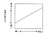
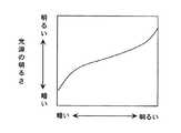
画像の明るさと光源の明るさ(光源ランプ5の発光強度)との関係は、図2に示すように、線形的な関係に設定してもよいし、図3に示すように非線形な関係に設定してもよい。さらに、図4に示すように、画像の明るさが所定の明るさになるまでは画像の明るさと光源の明るさとの関係を線形的な関係に設定し、画像の明るさが所定の明るさ以上である場合には光源の明るさが一定値となるような関係に設定してもよい。
【0018】
光源用冷却ファン速度制御部6は、信号内容判定部3から与えられた判定結果に応じて、光源用冷却ファン7の回転速度を制御する。つまり、光源用冷却ファン速度制御部6は、画像が明るいほど、光源用冷却ファン7の回転速度が速くなるように、光源用冷却ファン7の回転速度を制御する。
【0019】
なお、画像の明るさと光源用冷却ファン7の回転速度との関係は、画像の明るさと光源の明るさ(光源ランプ5の発光強度)との関係および光源ランプ5の明るさと発光部の温度との関係を考慮して、光源ランプ5の発光部の温度が好適な範囲に保たれるように設定される。
【0020】
光源用冷却ファン7とは異なる冷却ファン10は、冷却ファン速度制御部9によって制御される。冷却ファン速度制御部9には、液晶プロジェクタ本体内の温度を検出する温度センサ8の検出信号が入力している。冷却ファン速度制御部9は、温度センサ8によって検出された液晶プロジェクタ本体内の温度に基づいて、冷却ファン10の回転速度を制御する。つまり、冷却ファン速度制御部9は、液晶プロジェクタ本体内の温度が高くなるほど、冷却ファン10の回転速度が大きくなるように、冷却ファン10の回転速度を制御する。
【0021】
なお、温度センサ8の代わりに、液晶プロジェクタ本体の周辺温度を検出する温度センサを用いてもよい。
【0022】
〔2〕第2の実施の形態の説明
【0023】
図5は、液晶プロジェクタの構成を示している。図5において、図1と同じものには、同じ符号を付してその説明を省略する。
【0024】
温度センサ8Aとしては、この例では、液晶プロジェクタ本体の周辺温度を検出するものが用いられている。温度センサ8Aの検出信号は、冷却ファン速度制御部9に入力するとともに、光源用冷却ファン速度制御部6にも入力している。
【0025】
冷却ファン速度制御部9は、温度センサ8Aによって検出された液晶プロジェクタ本体の周辺温度に基づいて、冷却ファン10の回転速度を制御する。つまり、冷却ファン速度制御部9は、液晶プロジェクタ本体の周辺温度が高くなるほど、冷却ファン10の回転速度が大きくなるように、冷却ファン10の回転速度を制御する。
【0026】
光源用冷却ファン速度制御部6は、信号内容判定部3から与えられた判定結果および温度センサ8Aによって検出された液晶プロジェクタ本体の周辺温度に基づいて、光源用冷却ファン7の回転速度を制御する。つまり、光源用冷却ファン速度制御部6は、画像が明るいほど光源用冷却ファン7の回転速度が速くなるように、かつ液晶プロジェクタ本体の周辺温度が高いほど光源用冷却ファン7の回転速度が速くなるように、光源用冷却ファン7の回転速度を制御する。
【0027】
つまり、光源用冷却ファン速度制御部6は、画像の明るさの他、液晶プロジェクタ本体の周辺温度をも考慮して、光源用冷却ファン7の回転速度を制御している。
【0028】
具体的には、液晶プロジェクタ本体の周辺温度がとりうる温度範囲を複数段階に分類し、各段階の温度範囲毎に、画像の明るさの判定結果に対する光源用冷却ファン7の回転速度との関係を表すテーブルを用意しておく。そして、温度センサ8Aによって検出された液晶プロジェクタ本体の周辺温度に対応するテーブルと、画像の明るさの判定結果とに基づいて、光源用冷却ファン7の回転速度を決定する。
【0029】
なお、温度センサ8Aの代わりに、液晶プロジェクタ本体内の温度を検出する温度センサを用いてもよい。
【0030】
【発明の効果】
この発明によれば、表示する画像の特徴に応じて光源ランプの明るさを制御する投射型映像表示装置において、光源ランプの寿命を長く保持することが可能となる。
【図面の簡単な説明】
【図1】第1の実施の形態である液晶プロジェクタの構成を示すブロック図である。
【図2】画像の明るさと光源の明るさとの関係の一例を示すグラフである。
【図3】画像の明るさと光源の明るさとの関係の他の例を示すグラフである。
【図4】画像の明るさと光源の明るさとの関係のさらに他の例を示すグラフである。
【図5】第2の実施の形態である液晶プロジェクタの構成を示すブロック図である。
【符号の説明】
1 信号処理/LCD駆動部
2 LCD
3 信号内容判定部
4 調光制御部
5 光源ランプ
6 光源用冷却ファン速度制御部
7 光源用冷却ファン
8、8A 温度センサ[0001]
BACKGROUND OF THE INVENTION
The present invention relates to a projection type video display device such as an LCD projector or a DLP projector.
[0002]
[Prior art]
In a projection-type video display device that uses a display device such as an LCD or DLP as a light valve, a method has been proposed in which the brightness of the light source lamp is controlled according to the characteristics of the displayed image to improve the visual contrast. ing. Specifically, a device that determines the characteristics of an image by detecting the peak value of the image signal or the average video level of the image signal and controls the brightness of the light source lamp according to the determination result has already been developed. (See JP 06-160811, JP 03-179886).
[0003]
In addition, as a cooling fan control system for cooling the light source lamp, optical components, etc. in the projection type video display device, the temperature inside and outside the projection type video display device is detected by a temperature sensor, and cooling is performed based on the detected temperature. A method for controlling the rotational speed of the fan has already been developed (see Japanese Patent Laid-Open No. 2002-72170).
[0004]
By the way, as a light source lamp of a projection-type image display device, an ultrahigh pressure mercury lamp called UHP or UHE is generally used. A characteristic of these lamps is that they have high luminous efficiency. However, temperature management of the light emitting part is important in order to maintain high luminous efficiency and long life. In an example of a lamp, it is necessary to manage the temperature of the burner section at 950 ± 50 degrees, and the life tends to be shortened if the temperature is too high or too low.
[0005]
In a general projection display device, the brightness of the light source lamp is always kept constant. Therefore, the rotation speed of the cooling fan for cooling the light source lamp is determined according to the temperature inside and outside the projection display device. The temperature of the light emitting unit can be managed relatively easily by fixing the optimal value according to the above.
[0006]
On the other hand, in the projection type video display device that controls the brightness of the light source lamp according to the characteristics of the image to be displayed, the rotational speed of the cooling fan for cooling the light source lamp is set to the inside and outside of the projection type video display device. If the light source lamp is dimmed in the bright direction, it will be undercooled, and if it is dimmed in the dark direction, it will be overcooled. It causes shortening.
[0007]
[Patent Document 1]
Japanese Patent Laid-Open No. 06-160811 [Patent Document 2]
Japanese Patent Laid-Open No. 03-179886 [Patent Document 3]
Japanese Patent Laid-Open No. 2002-72170
[Problems to be solved by the invention]
It is an object of the present invention to provide a projection type video display apparatus that can maintain the life of a light source lamp for a long time in a projection type video display apparatus that controls the brightness of a light source lamp according to the characteristics of an image to be displayed. Objective.
[0009]
[Means for Solving the Problems]
According to a first aspect of the present invention, there is provided a projection-type image display apparatus including a light source lamp and a light valve that modulates the intensity of output light from the light source lamp, a light source lamp cooling fan for cooling the light source lamp, and an LCD Based on a cooling fan for cooling the vicinity, a temperature sensor for detecting the ambient temperature of the projection type video display device main body or the temperature in the projection type video display device main body, and the average luminance value of the entire display screen calculated from the image signal Based on the determination means for determining the brightness of the image, the first control means for controlling the light emission intensity of the light source lamp based on the determination result of the determination means, the determination result of the determination means and the detected temperature of the temperature sensor The second control means for controlling the rotational speed of the cooling fan for the light source lamp and the rotational speed of the cooling fan for cooling the vicinity of the LCD are controlled based on the temperature detected by the temperature sensor. The first control means controls the light emission intensity of the light source lamp so that the light emission intensity of the light source lamp increases as the image becomes brighter. The rotation speed of the light source lamp cooling fan is increased so that the brighter the image, the higher the rotation speed of the light source lamp cooling fan, and the higher the detected temperature of the temperature sensor, the higher the rotation speed of the light source lamp cooling fan. The third control means controls the rotation speed of the cooling fan for cooling the vicinity of the LCD so that the higher the temperature detected by the temperature sensor, the higher the rotation speed of the cooling fan for cooling the vicinity of the LCD. It is characterized by controlling.
[0011]
DETAILED DESCRIPTION OF THE INVENTION
DESCRIPTION OF THE PREFERRED EMBODIMENTS Embodiments of the present invention applied to a liquid crystal projector will be described below with reference to the drawings.
[0012]
[1] Description of the first embodiment
FIG. 1 shows the configuration of a liquid crystal projector.
[0014]
The image signal is sent to the
[0015]
The image signal is also sent to the signal content determination unit 3. For example, the signal content determination unit 3 calculates APL (average luminance value) of the entire display screen from the display image signal, and determines the brightness of the image based on the calculated average luminance value. In this example, the signal content determination unit 3 determines which range the brightness of the image corresponds to among the eight predetermined brightness ranges, and the determination result is used as the
[0016]
The
[0017]
The relationship between the brightness of the image and the brightness of the light source (the light emission intensity of the light source lamp 5) may be set to a linear relationship as shown in FIG. 2, or a non-linear relationship as shown in FIG. It may be set. Further, as shown in FIG. 4, until the brightness of the image reaches a predetermined brightness, the relationship between the brightness of the image and the brightness of the light source is set to a linear relationship, and the brightness of the image is set to the predetermined brightness. In such a case, the relationship may be set such that the brightness of the light source becomes a constant value.
[0018]
The light source cooling fan
[0019]
The relationship between the brightness of the image and the rotational speed of the light
[0020]
A cooling
[0021]
Instead of the temperature sensor 8, a temperature sensor that detects the ambient temperature of the liquid crystal projector main body may be used.
[0022]
[2] Description of the second embodiment
FIG. 5 shows the configuration of the liquid crystal projector. In FIG. 5, the same components as those in FIG.
[0024]
In this example, a
[0025]
The cooling fan
[0026]
The light source cooling fan
[0027]
That is, the light source cooling fan
[0028]
Specifically, the temperature range that the ambient temperature of the liquid crystal projector body can take is classified into a plurality of stages, and the relationship between the rotational speed of the light
[0029]
Instead of the
[0030]
【The invention's effect】
According to the present invention, in a projection display apparatus that controls the brightness of a light source lamp according to the characteristics of an image to be displayed, the life of the light source lamp can be kept long.
[Brief description of the drawings]
FIG. 1 is a block diagram illustrating a configuration of a liquid crystal projector according to a first embodiment.
FIG. 2 is a graph showing an example of a relationship between image brightness and light source brightness;
FIG. 3 is a graph showing another example of the relationship between image brightness and light source brightness.
FIG. 4 is a graph showing still another example of the relationship between image brightness and light source brightness.
FIG. 5 is a block diagram illustrating a configuration of a liquid crystal projector according to a second embodiment.
[Explanation of symbols]
1 Signal Processing /
3 Signal
Claims (1)
Translated fromJapanese光源ランプを冷却するための光源ランプ用冷却ファンと、
LCD近傍を冷却するための冷却ファンと、
投射型映像表示装置本体の周辺温度または投射型映像表示装置本体内の温度を検出する温度センサと、
画像信号から算出した表示画面全体の平均輝度値に基づいて、画像の明るさを判定する判定手段と、
判定手段の判定結果に基づいて、光源ランプの発光強度を制御する第1制御手段と、
判定手段の判定結果および温度センサの検出温度に基づいて、光源ランプ用冷却ファンの回転速度を制御する第2制御手段と、
温度センサの検出温度に基づいて、LCD近傍を冷却するための冷却ファンの回転速度を制御する第3制御手段とを備えており、
第1制御手段は、画像が明るいほど光源ランプの発光強度が大きくなるように、光源ランプの発光強度を制御するものであり、
第2制御手段は、画像が明るいほど光源ランプ用冷却ファンの回転速度が速くなるように、かつ温度センサの検出温度が高いほど光源ランプ用冷却ファンの回転速度が速くなるように、光源ランプ用冷却ファンの回転速度を制御するものであり、
第3制御手段は、温度センサの検出温度が高くなるほどLCD近傍を冷却するための冷却ファンの回転速度が速くなるように、LCD近傍を冷却するための冷却ファンの回転速度を制御するものであることを特徴とする投射型映像表示装置。In a projection-type image display device comprising a light source lamp and a light valve that modulates the intensity of output light from the light source lamp,
A cooling fan for the light source lamp for cooling the light source lamp;
A cooling fan for cooling the vicinity of the LCD;
A temperature sensor for detecting the ambient temperature of the projection type video display device body or the temperature in the projection type video display device body; and
Determination means for determining the brightness of the image based on the average luminance value of the entire display screen calculated from the image signal;
First control means for controlling the light emission intensity of the light source lamp based on the determination result of the determination means;
Second control means for controlling the rotational speed of the cooling fan for the light source lamp based on the determination result of the determination meansand the temperature detected by the temperature sensor ;
Third control means for controlling the rotation speed of the cooling fan for cooling the vicinity of the LCD based on the temperature detected by the temperature sensor,
The first control unit controls the light emission intensity of the light source lamp so that the light emission intensity of the light source lamp increases as the image becomes brighter.
The second control means is for the light source lamp so that the rotation speed of the light source lamp cooling fan is increased as the image is brighter and the rotation speed of the light source lamp cooling fan is increased as the detected temperature of the temperature sensor is higher. It controls the rotation speed of the cooling fan,
The third control means controls the rotational speed of the cooling fan for cooling the vicinity of the LCD so that the rotational speed of the cooling fan for cooling the vicinity of the LCD increases as the temperature detected by the temperature sensor increases. A projection-type image display device characterized by that.
Priority Applications (3)
| Application Number | Priority Date | Filing Date | Title |
|---|---|---|---|
| JP2003156445AJP4241194B2 (en) | 2003-06-02 | 2003-06-02 | Projection-type image display device |
| US10/857,357US7131731B2 (en) | 2003-06-02 | 2004-06-01 | Projection type video display apparatus |
| CN200410046047ACN100589025C (en) | 2003-06-02 | 2004-06-01 | Projection Image Display |
Applications Claiming Priority (1)
| Application Number | Priority Date | Filing Date | Title |
|---|---|---|---|
| JP2003156445AJP4241194B2 (en) | 2003-06-02 | 2003-06-02 | Projection-type image display device |
Publications (2)
| Publication Number | Publication Date |
|---|---|
| JP2004361462A JP2004361462A (en) | 2004-12-24 |
| JP4241194B2true JP4241194B2 (en) | 2009-03-18 |
Family
ID=34050529
Family Applications (1)
| Application Number | Title | Priority Date | Filing Date |
|---|---|---|---|
| JP2003156445AExpired - LifetimeJP4241194B2 (en) | 2003-06-02 | 2003-06-02 | Projection-type image display device |
Country Status (3)
| Country | Link |
|---|---|
| US (1) | US7131731B2 (en) |
| JP (1) | JP4241194B2 (en) |
| CN (1) | CN100589025C (en) |
Families Citing this family (33)
| Publication number | Priority date | Publication date | Assignee | Title |
|---|---|---|---|---|
| JP4270116B2 (en)* | 2004-11-30 | 2009-05-27 | ソニー株式会社 | Cooling device and projection display device |
| JP2006243551A (en)* | 2005-03-04 | 2006-09-14 | Toshiba Corp | Projector and projector lamp control |
| JP4036874B2 (en)* | 2005-07-19 | 2008-01-23 | 三洋電機株式会社 | Projector device |
| US20070024823A1 (en)* | 2005-07-29 | 2007-02-01 | Optoma Technology, Inc. | Methods and systems for improving operation of a video projector |
| TW200705084A (en)* | 2005-07-29 | 2007-02-01 | Coretronic Corp | Cooling system |
| JP2007212852A (en)* | 2006-02-10 | 2007-08-23 | Mitsubishi Electric Corp | Display device |
| JP2007279366A (en)* | 2006-04-06 | 2007-10-25 | Sharp Corp | projector |
| KR101183457B1 (en) | 2006-10-16 | 2012-09-14 | 삼성전자주식회사 | Liquid Crystal Display And Control Method Thereof |
| KR101315455B1 (en)* | 2007-01-09 | 2013-10-04 | 삼성전자주식회사 | Display apparatus and fan unit and fan speed control method thereof |
| JP2008233472A (en) | 2007-03-20 | 2008-10-02 | Canon Inc | Projection display |
| JP2008262101A (en)* | 2007-04-13 | 2008-10-30 | Mitsubishi Electric Corp | Video display apparatus and temperature prediction method for display section thereof |
| JP2011075763A (en)* | 2009-09-30 | 2011-04-14 | Sanyo Electric Co Ltd | Projection type video display device |
| CN102667617B (en) | 2009-11-24 | 2015-01-14 | Nec显示器解决方案株式会社 | Projection display device |
| JP5561804B2 (en)* | 2010-08-05 | 2014-07-30 | Necディスプレイソリューションズ株式会社 | Image display device and light source cooling method |
| US9104059B2 (en) | 2010-08-24 | 2015-08-11 | Nec Display Solutions, Ltd. | Image display device and light source cooling method |
| US8419193B2 (en)* | 2010-09-10 | 2013-04-16 | Himax Display, Inc. | Projection apparatus |
| JP5771997B2 (en)* | 2011-01-12 | 2015-09-02 | カシオ計算機株式会社 | Projection apparatus, projection method, and program |
| CN104011590B (en)* | 2012-01-13 | 2016-03-16 | Nec显示器解决方案株式会社 | Projection type display device and method for controlling operation of projection type display device |
| CN103149783A (en)* | 2013-02-22 | 2013-06-12 | 上海市金山区青少年活动中心 | Emergent projector cooling system based on bladeless fan |
| CN103149957A (en)* | 2013-02-22 | 2013-06-12 | 上海市金山区青少年活动中心 | Automatic voltage regulation (AVR) singlechip-based projector emergency cooling system and method |
| JP2014206581A (en)* | 2013-04-11 | 2014-10-30 | ソニー株式会社 | Projection-type display device and method for controlling projection-type display device |
| JP6197832B2 (en)* | 2015-06-30 | 2017-09-20 | カシオ計算機株式会社 | Projection apparatus, projection method, and program |
| CN107422591B (en)* | 2016-05-24 | 2020-02-07 | 中兴通讯股份有限公司 | Projector safe working method and device |
| GB201622220D0 (en)* | 2016-12-23 | 2017-02-08 | Barco Nv | Cooling system for spatial light modulating devices |
| JP2017204008A (en)* | 2017-08-10 | 2017-11-16 | カシオ計算機株式会社 | Irradiation control device, irradiation control method, and program |
| CN107763567A (en)* | 2017-11-21 | 2018-03-06 | 江门市华日摩托车配件有限公司 | A kind of intelligent motorcycle headlight |
| CN107942610A (en)* | 2017-11-28 | 2018-04-20 | 苏州佳世达光电有限公司 | Projector radiating control system and method |
| CN108594890B (en)* | 2017-12-13 | 2020-12-25 | 深圳市飓风智云科技有限公司 | Intelligent real-time dynamic temperature adjusting system and method for display device |
| CN108170180B (en)* | 2017-12-13 | 2020-12-25 | 深圳市飓风智云科技有限公司 | Intelligent real-time dynamic cooling system and method for display device |
| CN110462548A (en)* | 2018-03-29 | 2019-11-15 | 深圳市大疆创新科技有限公司 | Control method, display equipment, remote controler and the unmanned plane suit of fan |
| CN108678984A (en)* | 2018-04-09 | 2018-10-19 | 深圳市火乐科技发展有限公司 | A kind of autocontrol method and system based on projecting apparatus fan |
| JP7554971B2 (en)* | 2019-03-04 | 2024-09-24 | パナソニックIpマネジメント株式会社 | VIDEO DISPLAY SYSTEM, VIDEO CONVERSION DEVICE, AND VIDEO DISPLAY METHOD |
| CN115755505B (en)* | 2021-09-02 | 2025-07-18 | 成都极米科技股份有限公司 | Projector control method, device, system, equipment and storage medium |
Family Cites Families (9)
| Publication number | Priority date | Publication date | Assignee | Title |
|---|---|---|---|---|
| US4283658A (en)* | 1979-06-13 | 1981-08-11 | Bell & Howell Company | Projection lamp control arrangement |
| JPH03179886A (en) | 1989-12-07 | 1991-08-05 | Toshiba Corp | Projection type liquid crystal display device |
| JPH06160811A (en) | 1992-11-26 | 1994-06-07 | Sanyo Electric Co Ltd | Liquid crystal projector |
| US6184969B1 (en)* | 1994-10-25 | 2001-02-06 | James L. Fergason | Optical display system and method, active and passive dithering using birefringence, color image superpositioning and display enhancement |
| JP2002072170A (en) | 2000-08-23 | 2002-03-12 | Sanyo Electric Co Ltd | Liquid crystal projector |
| JP4588230B2 (en)* | 2001-02-27 | 2010-11-24 | 三菱電機株式会社 | Projection-type image display device |
| JP2002300498A (en)* | 2001-03-30 | 2002-10-11 | Fujitsu General Ltd | LCD projector |
| JP2004354717A (en)* | 2003-05-29 | 2004-12-16 | Seiko Epson Corp | Display device and projection display device |
| JP2005106951A (en)* | 2003-09-29 | 2005-04-21 | Seiko Epson Corp | Drive control of projector and light source lamp for projector |
- 2003
- 2003-06-02JPJP2003156445Apatent/JP4241194B2/ennot_activeExpired - Lifetime
- 2004
- 2004-06-01USUS10/857,357patent/US7131731B2/ennot_activeExpired - Lifetime
- 2004-06-01CNCN200410046047Apatent/CN100589025C/ennot_activeExpired - Fee Related
Also Published As
| Publication number | Publication date |
|---|---|
| CN100589025C (en) | 2010-02-10 |
| US7131731B2 (en) | 2006-11-07 |
| US20050030485A1 (en) | 2005-02-10 |
| CN1573517A (en) | 2005-02-02 |
| JP2004361462A (en) | 2004-12-24 |
Similar Documents
| Publication | Publication Date | Title |
|---|---|---|
| JP4241194B2 (en) | Projection-type image display device | |
| CN103080835B (en) | Image display device and light source cooling method | |
| CN100353219C (en) | Illuminator, projection display device and method for driving the same | |
| JP4107266B2 (en) | Display device and dimming method thereof | |
| CN101551977B (en) | Display apparatus and light control method of the same | |
| JP4717232B2 (en) | Projector device | |
| WO2005009035A1 (en) | Image display | |
| CN103080834B (en) | Image display device and light source cooling method | |
| CN102955336B (en) | Projection display device and control method thereof | |
| US7809209B2 (en) | Image display device, and control method for the same | |
| CN102667617B (en) | Projection display device | |
| JP4238640B2 (en) | Illumination device, projection display device, and driving method thereof | |
| JP2000028988A (en) | LCD projector | |
| CN102866569B (en) | Projector and control method of the same | |
| JP2007264394A (en) | Projection type video display device | |
| CN100561303C (en) | Dynamic adjustment of counter electrode voltage of liquid crystal panel corresponding to dimming of illumination light | |
| JP2004110050A (en) | Image display device and image display method | |
| JP2018013656A (en) | Projection type display device | |
| JP2005227478A (en) | Image display device | |
| KR20050113737A (en) | Lamp cooling device | |
| JPH0736131U (en) | LCD projector | |
| KR20030087478A (en) | Method for control light screen of projection display system |
Legal Events
| Date | Code | Title | Description |
|---|---|---|---|
| A621 | Written request for application examination | Free format text:JAPANESE INTERMEDIATE CODE: A621 Effective date:20060317 | |
| A977 | Report on retrieval | Free format text:JAPANESE INTERMEDIATE CODE: A971007 Effective date:20080623 | |
| A131 | Notification of reasons for refusal | Free format text:JAPANESE INTERMEDIATE CODE: A131 Effective date:20080626 | |
| A521 | Request for written amendment filed | Free format text:JAPANESE INTERMEDIATE CODE: A523 Effective date:20080807 | |
| A131 | Notification of reasons for refusal | Free format text:JAPANESE INTERMEDIATE CODE: A131 Effective date:20080821 | |
| A521 | Request for written amendment filed | Free format text:JAPANESE INTERMEDIATE CODE: A523 Effective date:20081007 | |
| A131 | Notification of reasons for refusal | Free format text:JAPANESE INTERMEDIATE CODE: A131 Effective date:20081023 | |
| A521 | Request for written amendment filed | Free format text:JAPANESE INTERMEDIATE CODE: A523 Effective date:20081114 | |
| TRDD | Decision of grant or rejection written | ||
| A01 | Written decision to grant a patent or to grant a registration (utility model) | Free format text:JAPANESE INTERMEDIATE CODE: A01 Effective date:20081127 | |
| A01 | Written decision to grant a patent or to grant a registration (utility model) | Free format text:JAPANESE INTERMEDIATE CODE: A01 | |
| A61 | First payment of annual fees (during grant procedure) | Free format text:JAPANESE INTERMEDIATE CODE: A61 Effective date:20081222 | |
| FPAY | Renewal fee payment (event date is renewal date of database) | Free format text:PAYMENT UNTIL: 20120109 Year of fee payment:3 | |
| R151 | Written notification of patent or utility model registration | Ref document number:4241194 Country of ref document:JP Free format text:JAPANESE INTERMEDIATE CODE: R151 | |
| FPAY | Renewal fee payment (event date is renewal date of database) | Free format text:PAYMENT UNTIL: 20120109 Year of fee payment:3 | |
| FPAY | Renewal fee payment (event date is renewal date of database) | Free format text:PAYMENT UNTIL: 20130109 Year of fee payment:4 | |
| FPAY | Renewal fee payment (event date is renewal date of database) | Free format text:PAYMENT UNTIL: 20140109 Year of fee payment:5 | |
| EXPY | Cancellation because of completion of term |