JP4240852B2 - Electric machine drive control device, electric machine drive control method, and program thereof - Google Patents
Electric machine drive control device, electric machine drive control method, and program thereofDownload PDFInfo
- Publication number
- JP4240852B2 JP4240852B2JP2001199918AJP2001199918AJP4240852B2JP 4240852 B2JP4240852 B2JP 4240852B2JP 2001199918 AJP2001199918 AJP 2001199918AJP 2001199918 AJP2001199918 AJP 2001199918AJP 4240852 B2JP4240852 B2JP 4240852B2
- Authority
- JP
- Japan
- Prior art keywords
- electric machine
- command value
- current
- processing means
- generator
- Prior art date
- Legal status (The legal status is an assumption and is not a legal conclusion. Google has not performed a legal analysis and makes no representation as to the accuracy of the status listed.)
- Expired - Fee Related
Links
- 238000000034methodMethods0.000titleclaimsdescription15
- 238000002347injectionMethods0.000claimsdescription30
- 239000007924injectionSubstances0.000claimsdescription30
- 238000004364calculation methodMethods0.000claimsdescription24
- 238000010586diagramMethods0.000description16
- 238000006243chemical reactionMethods0.000description10
- 238000001514detection methodMethods0.000description6
- 230000005540biological transmissionEffects0.000description5
- 239000000446fuelSubstances0.000description5
- 239000003990capacitorSubstances0.000description3
- 238000010248power generationMethods0.000description3
- 230000006870functionEffects0.000description2
- 238000009499grossingMethods0.000description2
- 230000008929regenerationEffects0.000description2
- 238000011069regeneration methodMethods0.000description2
- 230000000694effectsEffects0.000description1
- 230000004044responseEffects0.000description1
Images


Classifications
- B—PERFORMING OPERATIONS; TRANSPORTING
- B60—VEHICLES IN GENERAL
- B60L—PROPULSION OF ELECTRICALLY-PROPELLED VEHICLES; SUPPLYING ELECTRIC POWER FOR AUXILIARY EQUIPMENT OF ELECTRICALLY-PROPELLED VEHICLES; ELECTRODYNAMIC BRAKE SYSTEMS FOR VEHICLES IN GENERAL; MAGNETIC SUSPENSION OR LEVITATION FOR VEHICLES; MONITORING OPERATING VARIABLES OF ELECTRICALLY-PROPELLED VEHICLES; ELECTRIC SAFETY DEVICES FOR ELECTRICALLY-PROPELLED VEHICLES
- B60L15/00—Methods, circuits, or devices for controlling the traction-motor speed of electrically-propelled vehicles
- B60L15/20—Methods, circuits, or devices for controlling the traction-motor speed of electrically-propelled vehicles for control of the vehicle or its driving motor to achieve a desired performance, e.g. speed, torque, programmed variation of speed
- B60L15/2045—Methods, circuits, or devices for controlling the traction-motor speed of electrically-propelled vehicles for control of the vehicle or its driving motor to achieve a desired performance, e.g. speed, torque, programmed variation of speed for optimising the use of energy
- B—PERFORMING OPERATIONS; TRANSPORTING
- B60—VEHICLES IN GENERAL
- B60L—PROPULSION OF ELECTRICALLY-PROPELLED VEHICLES; SUPPLYING ELECTRIC POWER FOR AUXILIARY EQUIPMENT OF ELECTRICALLY-PROPELLED VEHICLES; ELECTRODYNAMIC BRAKE SYSTEMS FOR VEHICLES IN GENERAL; MAGNETIC SUSPENSION OR LEVITATION FOR VEHICLES; MONITORING OPERATING VARIABLES OF ELECTRICALLY-PROPELLED VEHICLES; ELECTRIC SAFETY DEVICES FOR ELECTRICALLY-PROPELLED VEHICLES
- B60L15/00—Methods, circuits, or devices for controlling the traction-motor speed of electrically-propelled vehicles
- B60L15/02—Methods, circuits, or devices for controlling the traction-motor speed of electrically-propelled vehicles characterised by the form of the current used in the control circuit
- B60L15/025—Methods, circuits, or devices for controlling the traction-motor speed of electrically-propelled vehicles characterised by the form of the current used in the control circuit using field orientation; Vector control; Direct Torque Control [DTC]
- B—PERFORMING OPERATIONS; TRANSPORTING
- B60—VEHICLES IN GENERAL
- B60L—PROPULSION OF ELECTRICALLY-PROPELLED VEHICLES; SUPPLYING ELECTRIC POWER FOR AUXILIARY EQUIPMENT OF ELECTRICALLY-PROPELLED VEHICLES; ELECTRODYNAMIC BRAKE SYSTEMS FOR VEHICLES IN GENERAL; MAGNETIC SUSPENSION OR LEVITATION FOR VEHICLES; MONITORING OPERATING VARIABLES OF ELECTRICALLY-PROPELLED VEHICLES; ELECTRIC SAFETY DEVICES FOR ELECTRICALLY-PROPELLED VEHICLES
- B60L50/00—Electric propulsion with power supplied within the vehicle
- B60L50/10—Electric propulsion with power supplied within the vehicle using propulsion power supplied by engine-driven generators, e.g. generators driven by combustion engines
- B60L50/16—Electric propulsion with power supplied within the vehicle using propulsion power supplied by engine-driven generators, e.g. generators driven by combustion engines with provision for separate direct mechanical propulsion
- B—PERFORMING OPERATIONS; TRANSPORTING
- B60—VEHICLES IN GENERAL
- B60L—PROPULSION OF ELECTRICALLY-PROPELLED VEHICLES; SUPPLYING ELECTRIC POWER FOR AUXILIARY EQUIPMENT OF ELECTRICALLY-PROPELLED VEHICLES; ELECTRODYNAMIC BRAKE SYSTEMS FOR VEHICLES IN GENERAL; MAGNETIC SUSPENSION OR LEVITATION FOR VEHICLES; MONITORING OPERATING VARIABLES OF ELECTRICALLY-PROPELLED VEHICLES; ELECTRIC SAFETY DEVICES FOR ELECTRICALLY-PROPELLED VEHICLES
- B60L50/00—Electric propulsion with power supplied within the vehicle
- B60L50/50—Electric propulsion with power supplied within the vehicle using propulsion power supplied by batteries or fuel cells
- B60L50/60—Electric propulsion with power supplied within the vehicle using propulsion power supplied by batteries or fuel cells using power supplied by batteries
- B60L50/61—Electric propulsion with power supplied within the vehicle using propulsion power supplied by batteries or fuel cells using power supplied by batteries by batteries charged by engine-driven generators, e.g. series hybrid electric vehicles
- B—PERFORMING OPERATIONS; TRANSPORTING
- B60—VEHICLES IN GENERAL
- B60L—PROPULSION OF ELECTRICALLY-PROPELLED VEHICLES; SUPPLYING ELECTRIC POWER FOR AUXILIARY EQUIPMENT OF ELECTRICALLY-PROPELLED VEHICLES; ELECTRODYNAMIC BRAKE SYSTEMS FOR VEHICLES IN GENERAL; MAGNETIC SUSPENSION OR LEVITATION FOR VEHICLES; MONITORING OPERATING VARIABLES OF ELECTRICALLY-PROPELLED VEHICLES; ELECTRIC SAFETY DEVICES FOR ELECTRICALLY-PROPELLED VEHICLES
- B60L2220/00—Electrical machine types; Structures or applications thereof
- B60L2220/10—Electrical machine types
- B60L2220/16—DC brushless machines
- Y—GENERAL TAGGING OF NEW TECHNOLOGICAL DEVELOPMENTS; GENERAL TAGGING OF CROSS-SECTIONAL TECHNOLOGIES SPANNING OVER SEVERAL SECTIONS OF THE IPC; TECHNICAL SUBJECTS COVERED BY FORMER USPC CROSS-REFERENCE ART COLLECTIONS [XRACs] AND DIGESTS
- Y02—TECHNOLOGIES OR APPLICATIONS FOR MITIGATION OR ADAPTATION AGAINST CLIMATE CHANGE
- Y02T—CLIMATE CHANGE MITIGATION TECHNOLOGIES RELATED TO TRANSPORTATION
- Y02T10/00—Road transport of goods or passengers
- Y02T10/60—Other road transportation technologies with climate change mitigation effect
- Y02T10/62—Hybrid vehicles
- Y—GENERAL TAGGING OF NEW TECHNOLOGICAL DEVELOPMENTS; GENERAL TAGGING OF CROSS-SECTIONAL TECHNOLOGIES SPANNING OVER SEVERAL SECTIONS OF THE IPC; TECHNICAL SUBJECTS COVERED BY FORMER USPC CROSS-REFERENCE ART COLLECTIONS [XRACs] AND DIGESTS
- Y02—TECHNOLOGIES OR APPLICATIONS FOR MITIGATION OR ADAPTATION AGAINST CLIMATE CHANGE
- Y02T—CLIMATE CHANGE MITIGATION TECHNOLOGIES RELATED TO TRANSPORTATION
- Y02T10/00—Road transport of goods or passengers
- Y02T10/60—Other road transportation technologies with climate change mitigation effect
- Y02T10/64—Electric machine technologies in electromobility
- Y—GENERAL TAGGING OF NEW TECHNOLOGICAL DEVELOPMENTS; GENERAL TAGGING OF CROSS-SECTIONAL TECHNOLOGIES SPANNING OVER SEVERAL SECTIONS OF THE IPC; TECHNICAL SUBJECTS COVERED BY FORMER USPC CROSS-REFERENCE ART COLLECTIONS [XRACs] AND DIGESTS
- Y02—TECHNOLOGIES OR APPLICATIONS FOR MITIGATION OR ADAPTATION AGAINST CLIMATE CHANGE
- Y02T—CLIMATE CHANGE MITIGATION TECHNOLOGIES RELATED TO TRANSPORTATION
- Y02T10/00—Road transport of goods or passengers
- Y02T10/60—Other road transportation technologies with climate change mitigation effect
- Y02T10/70—Energy storage systems for electromobility, e.g. batteries
- Y—GENERAL TAGGING OF NEW TECHNOLOGICAL DEVELOPMENTS; GENERAL TAGGING OF CROSS-SECTIONAL TECHNOLOGIES SPANNING OVER SEVERAL SECTIONS OF THE IPC; TECHNICAL SUBJECTS COVERED BY FORMER USPC CROSS-REFERENCE ART COLLECTIONS [XRACs] AND DIGESTS
- Y02—TECHNOLOGIES OR APPLICATIONS FOR MITIGATION OR ADAPTATION AGAINST CLIMATE CHANGE
- Y02T—CLIMATE CHANGE MITIGATION TECHNOLOGIES RELATED TO TRANSPORTATION
- Y02T10/00—Road transport of goods or passengers
- Y02T10/60—Other road transportation technologies with climate change mitigation effect
- Y02T10/7072—Electromobility specific charging systems or methods for batteries, ultracapacitors, supercapacitors or double-layer capacitors
- Y—GENERAL TAGGING OF NEW TECHNOLOGICAL DEVELOPMENTS; GENERAL TAGGING OF CROSS-SECTIONAL TECHNOLOGIES SPANNING OVER SEVERAL SECTIONS OF THE IPC; TECHNICAL SUBJECTS COVERED BY FORMER USPC CROSS-REFERENCE ART COLLECTIONS [XRACs] AND DIGESTS
- Y02—TECHNOLOGIES OR APPLICATIONS FOR MITIGATION OR ADAPTATION AGAINST CLIMATE CHANGE
- Y02T—CLIMATE CHANGE MITIGATION TECHNOLOGIES RELATED TO TRANSPORTATION
- Y02T10/00—Road transport of goods or passengers
- Y02T10/60—Other road transportation technologies with climate change mitigation effect
- Y02T10/72—Electric energy management in electromobility
Landscapes
- Engineering & Computer Science (AREA)
- Power Engineering (AREA)
- Transportation (AREA)
- Mechanical Engineering (AREA)
- Life Sciences & Earth Sciences (AREA)
- Sustainable Development (AREA)
- Sustainable Energy (AREA)
- Electric Propulsion And Braking For Vehicles (AREA)
- Control Of Ac Motors In General (AREA)
- Hybrid Electric Vehicles (AREA)
- Retarders (AREA)
- Control Of Motors That Do Not Use Commutators (AREA)
- Arrangement Of Transmissions (AREA)
- Regulating Braking Force (AREA)
Description
Translated fromJapanese【0001】
【発明の属する技術分野】
本発明は、電動機械駆動制御装置、電動機械駆動制御方法及びそのプログラムに関するものである。
【0002】
【従来の技術】
従来、例えば、エンジンのトルク、すなわち、エンジントルクの一部を電動機械としての発電機(発電機モータ)に、残りを駆動輪に伝達するようにしたハイブリッド型車両においては、サンギヤ、リングギヤ及びキャリヤを備えたプラネタリギヤユニットを有し、前記キャリヤとエンジンとを連結し、リングギヤと駆動輪とを連結し、サンギヤと発電機とを連結し、前記リングギヤ及び駆動モータから出力された回転を駆動輪に伝達して駆動力を発生させるようにしている。
【0003】
この種のハイブリッド型車両においては、回転速度が低い領域において、エンジンの効率が極めて低く、駆動モータのトルク、すなわち、駆動モータトルクがエンジントルクより大きいので、発進時には、駆動モータだけが駆動され、エンジンの駆動が停止させられ、ハイブリッド型車両はモータ駆動モードで走行させられる。このとき、エンジンには摺(しゅう)動抵抗があり、しかも、発電機と比べてイナーシャが大きいので、エンジンは回転することなく、発電機は振り回される。そして、発進後、車速がエンジンを始動するのに適したエンジン始動車速に到達すると、発電機を駆動することによって、エンジンの回転速度、すなわち、エンジン回転速度を点火に適した回転速度まで高くしてエンジンを始動し、その後、駆動モータ及びエンジンが駆動されて、ハイブリッド型車両はモータ・エンジン駆動モードで走行させられる。その後、発電機のトルク、すなわち、発電機トルクが制御され、エンジントルクを支えるのに必要な反力が発生させられる。
【0004】
ところで、前記発電機は、回転自在に配設され、N極及びS極の磁極対を備えたロータ、及び該ロータより径方向外方に配設され、U相、V相及びW相のステータコイルを備えたステータを備え、電動機械制御装置としての発電機制御装置によってU相、V相及びW相の電流を前記ステータコイルに供給し、かつ、所定の電圧を印加することにより、前記発電機を駆動し、発電機トルクを発生させるようになっている。
【0005】
そして、前記発電機制御装置において、前記ステータコイルに供給される電流を電流センサによって検出電流として検出するとともに、前記ロータの磁極の位置、すなわち、磁極位置をレゾルバによって検出磁極位置として検出し、検出電流及び検出磁極位置を発電機制御部に送るようになっている。そして、該発電機制御部は前記検出電流、検出磁極位置、及び車両制御回路から送られた発電機トルクの目標値を表す発電機目標トルク(トルク指令値)に基づいてインバータを駆動する。
【0006】
そのために、前記発電機制御部においては、ロータの磁極対の方向にd軸を、該d軸と直角の方向にq軸をそれぞれ採ったd−q軸モデル上でベクトル制御演算によるフィードバック制御が行われ、前記発電機目標トルクに基づいてd軸電流指令値及びq軸電流指令値が発生させられ、該d軸電流指令値及びq軸電流指令値に基づいて、d軸電圧指令値及びq軸電圧指令値が発生させられる。
【0007】
ところが、前記レゾルバを使用すると、磁極位置の検出精度、及び発電機の制御性を向上させることはできるが、発電機制御装置のコストが高くなってしまう。そこで、前記レゾルバ等のセンサを使用することなく、磁極位置を算出するようにした磁極位置算出方法が提供されている。
【0008】
該磁極位置算出方法においては、まず、所定の磁極位置を初期値として推定し、推定された磁極位置に基づいて推定d−q座標を想定し、該推定d−q座標においてd軸電流指令値及びq軸電流指令値を発生させる。続いて、d軸電流指令値及びq軸電流指令値のうちの少なくとも一方に高周波電流を注入することによって、前記d軸電圧指令値及びq軸電圧指令値に高周波電圧を発生させる。この場合、該高周波電圧が発生させられたd軸電圧指令値及びq軸電圧指令値には、d軸インダクタンスとq軸インダクタンスとの差による推定された磁極位置と実際の磁極位置との誤差情報が含まれる。該誤差情報を小さくするように制御を行うと、推定された磁極位置と実際の磁極位置との差がなくなり、磁極位置が電気角で算出される。
【0009】
【発明が解決しようとする課題】
しかしながら、前記従来の発電機制御装置においては、d軸電流指令値及びq軸電流指令値のうちの少なくとも一方に、常時、高周波電流が注入されるので、d軸電流指令値及びq軸電流指令値が零(0)の場合、すなわち、発電機の制御が必要ない場合でも、本来ならば不必要である磁極位置を算出するために高周波電流が注入されることになり、限られた容量のバッテリの消費電力が大きくなり、ハイブリッド型車両の燃費が悪くなってしまう。
【0010】
本発明は、前記従来の発電機制御装置の問題点を解決して、バッテリの消費電力を小さくすることができ、ハイブリッド型車両の燃費を良くすることができる電動機械駆動制御装置、電動機械駆動制御方法及びそのプログラムを提供することを目的とする。
【0011】
【課題を解決するための手段】
そのために、本発明の電動機械駆動制御装置においては、電動機械と、該電動機械の回転を機械的に停止させる電動機械ブレーキと、電動機械トルクの目標値を表す電動機械目標トルクに基づいて電流指令値を発生させる電流指令値発生処理手段と、高周波電流を発生させる高周波電流発生処理手段と、前記電流指令値に高周波電流を注入する高周波電流注入処理手段と、高周波電流が注入された電流指令値、及び電動機械のコイルを流れる電流に基づいて電圧指令値を発生させる電圧指令値発生処理手段と、該電圧指令値発生処理手段によって発生させられた電圧指令値に基づいて前記電動機械を駆動する電動機械駆動処理手段と、前記電圧指令値発生処理手段と電動機械との間において発生させられた電圧変量を読み込み、該電圧変量に基づいて磁極位置を算出する磁極位置算出処理手段と、前記電動機械ブレーキを係合させるための電動機械ブレーキ係合要求を発生させる電動機械ブレーキ制御処理手段と、前記電動機械ブレーキ係合要求がある場合に、前記電流指令値への高周波電流の注入を停止させる高周波電流注入停止処理手段とを有する。
【0012】
本発明の他の電動機械駆動制御装置においては、さらに、前記電圧変量は前記電圧指令値である。
【0013】
本発明の更に他の電動機械駆動制御装置においては、さらに、前記電動機械ブレーキ制御処理手段は、電動機械ブレーキ係合要求が解除された場合に、前記電流指令値への高周波電流の注入が開始された後、一定時間が経過したときに電動機械ブレーキを解放する。
【0014】
本発明の更に他の電動機械駆動制御装置においては、さらに、前記電動機械は、エンジンと差動回転自在に、かつ、機械的に連結される。
【0015】
本発明の更に他の電動機械駆動制御装置においては、さらに、前記電動機械、エンジン、及び他の電動機械がプラネタリギヤユニットを介して連結される。
【0016】
本発明の電動機械駆動制御方法においては、電動機械トルクの目標値を表す電動機械目標トルクに基づいて電流指令値を発生させ、高周波電流を発生させ、前記電流指令値に高周波電流を注入し、高周波電流が注入された電流指令値、及び電動機械のコイルを流れる電流に基づいて電圧指令値を発生させ、該電圧指令値に基づいて電動機械を駆動し、電圧指令値発生手段と電動機械との間において発生させられた電圧変量を読み込み、該電圧変量に基づいて磁極位置を算出し、電動機械ブレーキを係合させるための電動機械ブレーキ係合要求を発生させ、該電動機械ブレーキ係合要求がある場合に、前記電流指令値への高周波電流の注入を停止させる。
【0017】
本発明の電動機械駆動制御方法のプログラムにおいては、コンピュータを、電動機械トルクの目標値を表す電動機械目標トルクに基づいて電流指令値を発生させる電流指令値発生処理手段、高周波電流を発生させる高周波電流発生処理手段、前記電流指令値に高周波電流を注入する高周波電流注入処理手段、高周波電流が注入された電流指令値、及び電動機械のコイルを流れる電流に基づいて電圧指令値を発生させる電圧指令値発生処理手段、該電圧指令値発生処理手段によって発生させられた電圧指令値に基づいて前記電動機械を駆動する電動機械駆動処理手段、前記電圧指令値発生手段と電動機械との間において発生させられた電圧変量を読み込み、該電圧変量に基づいて磁極位置を算出する磁極位置算出処理手段、電動機械ブレーキを係合させるための電動機械ブレーキ係合要求を発生させる電動機械ブレーキ制御処理手段、並びに前記電動機械ブレーキ係合要求がある場合に、前記電流指令値への高周波電流の注入を停止させる高周波電流注入停止処理手段として機能させる。
【0018】
【発明の実施の形態】
以下、本発明の実施の形態について図面を参照しながら詳細に説明する。なお、電動機械駆動制御装置としての発電機駆動制御装置について説明する。
【0019】
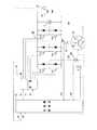
図1は本発明の実施の形態における発電機駆動制御装置の機能ブロック図である。
【0020】
図において、16は第1の電動機械としての発電機、Bは該発電機16の回転を機械的に停止させる電動機械ブレーキとしての発電機ブレーキ、101は電動機械トルクとしての発電機トルクの目標値を表す電動機械目標トルクとしての発電機目標トルクに基づいて電流指令値を発生させる電流指令値発生処理手段としてのトルク指令・電流指令変換部、104は高周波電流を発生させる高周波電流発生処理手段としての高周波電流発生部、91は前記電流指令値に高周波電流を注入する高周波電流注入処理手段としての高周波電流注入部、92は高周波電流が注入された電流指令値、及び発電機16の図示されないコイルを流れる電流に基づいて電圧指令値を発生させる電圧指令値発生処理手段としての電圧指令値発生部、93は該電圧指令値発生部92によって発生させられた電圧指令値に基づいて前記発電機16を駆動する電動機械駆動処理手段、82は前記電圧指令値発生部92と発電機16との間において発生させられた電圧変量を読み込み、該電圧変量に基づいて磁極位置を算出する磁極位置算出処理手段としての磁極位置算出部、94は前記発電機ブレーキBを係合させるための電動機械ブレーキ係合要求としての発電機ブレーキ係合要求を発生させる電動機械ブレーキ制御処理手段、86は前記発電機ブレーキ係合要求がある場合に、前記電流指令値への高周波電流の注入を停止させる高周波電流注入停止処理手段としての高周波電流制御部である。
【0021】
図2は本発明の実施の形態におけるハイブリッド型車両の概念図である。
【0022】
図において、11は第1の軸線上に配設されたエンジン(E/G)、12は前記第1の軸線上に配設され、前記エンジン11を駆動することによって発生させられた回転を出力する出力軸、13は前記第1の軸線上に配設され、前記出力軸12を介して入力された回転に対して変速を行う差動歯車装置としてのプラネタリギヤユニット、14は前記第1の軸線上に配設され、前記プラネタリギヤユニット13における変速後の回転が出力される出力軸、15は該出力軸14に固定された出力ギヤとしての第1のカウンタドライブギヤ、16は前記第1の軸線上に配設され、伝達軸17を介して前記プラネタリギヤユニット13と連結され、更にエンジン11と差動回転自在に、かつ、機械的に連結された第1の電動機械としての発電機(G)である。
【0023】
前記出力軸14はスリーブ形状を有し、前記出力軸12を包囲して配設される。また、前記第1のカウンタドライブギヤ15はプラネタリギヤユニット13よりエンジン11側に配設される。
【0024】
そして、前記プラネタリギヤユニット13は、少なくとも、第1の歯車要素としてのサンギヤS、該サンギヤSと噛(し)合するピニオンP、該ピニオンPと噛合する第2の歯車要素としてのリングギヤR、及び前記ピニオンPを回転自在に支持する第3の歯車要素としてのキャリヤCRを備え、前記サンギヤSは前記伝達軸17を介して発電機16と、リングギヤRは、出力軸14及び所定のギヤ列を介して、前記第1の軸線と平行な第2の軸線上に配設され、前記エンジン11及び発電機16と差動回転自在に、かつ、機械的に連結された他の電動機械及び第2の電動機械としての駆動モータ(M)25及び駆動輪37と、キャリヤCRは出力軸12を介してエンジン11と連結される。また、前記キャリヤCRとハイブリッド型車両駆動装置のケース10との間にワンウェイクラッチFが配設され、該ワンウェイクラッチFは、エンジン11から正方向の回転がキャリヤCRに伝達されたときにフリーになり、発電機16又は駆動モータ25から逆方向の回転がキャリヤCRに伝達されたときにロックされ、逆方向の回転がエンジン11に伝達されないようにする。
【0025】
さらに、前記発電機16は、前記伝達軸17に固定され、回転自在に配設されたロータ21、該ロータ21の周囲に配設されたステータ22、及び該ステータ22に巻装されたコイル23から成る。前記発電機16は、伝達軸17を介して伝達される回転によって電力を発生させる。前記コイル23は、図示されないバッテリに接続され、該バッテリに直流の電流を供給する。前記ロータ21と前記ケース10との間に電動機械ブレーキとしての発電機ブレーキBが配設され、該発電機ブレーキBを係合させることによってロータ21を選択的に固定し、発電機16の回転を機械的に停止させることができる。
【0026】
また、26は前記第2の軸線上に配設され、前記駆動モータ25の回転が出力される出力軸、27は該出力軸26に固定された出力ギヤとしての第2のカウンタドライブギヤである。前記駆動モータ25は、前記出力軸26に固定され、回転自在に配設されたロータ40、該ロータ40の周囲に配設されたステータ41、及び該ステータ41に巻装されたコイル42から成る。
【0027】
前記駆動モータ25は、コイル42に供給される電流によって駆動モータトルクを発生させる。そのために、前記コイル42は前記バッテリに接続され、該バッテリからの直流の電流が交流の電流に変換されて供給されるようになっている。
【0028】
そして、該駆動輪37をエンジン11の回転と同じ方向に回転させるために、前記第1、第2の軸線と平行な第3の軸線上にカウンタシャフト30が配設され、該カウンタシャフト30に、第1のカウンタドリブンギヤ31、及び該第1のカウンタドリブンギヤ31より歯数が多い第2のカウンタドリブンギヤ32が固定される。前記第1のカウンタドリブンギヤ31と前記第1のカウンタドライブギヤ15とが、また、前記第2のカウンタドリブンギヤ32と前記第2のカウンタドライブギヤ27とが噛合させられ、前記第1のカウンタドライブギヤ15の回転が反転されて第1のカウンタドリブンギヤ31に、前記第2のカウンタドライブギヤ27の回転が反転されて第2のカウンタドリブンギヤ32に伝達されるようになっている。さらに、前記カウンタシャフト30には前記第1のカウンタドリブンギヤ31より歯数が少ないデフピニオンギヤ33が固定される。
【0029】
そして、前記第1〜第3の軸線と平行な第4の軸線上にディファレンシャル装置36が配設され、該ディファレンシャル装置36のデフリングギヤ35と前記デフピニオンギヤ33とが噛合させられる。したがって、デフリングギヤ35に伝達された回転が前記ディファレンシャル装置36によって分配され、駆動輪37に伝達される。このように、エンジン11によって発生させられた回転を第1のカウンタドリブンギヤ31に伝達することができるだけでなく、駆動モータ25によって発生させられた回転を第2のカウンタドリブンギヤ32に伝達することができるので、エンジン11及び駆動モータ25を駆動することによってハイブリッド型車両を走行させることができる。
【0030】
次に、前記プラネタリギヤユニット13の動作について説明する。
【0031】
図3は本発明の実施の形態におけるプラネタリギヤユニットの動作説明図、図4は本発明の実施の形態における通常走行時の車速線図、図5は本発明の実施の形態における通常走行時のトルク線図である。
【0032】
プラネタリギヤユニット13(図2)においては、キャリヤCRがエンジン11と、サンギヤSが発電機16と、リングギヤRが出力軸14を介して前記駆動モータ25及び駆動輪37とそれぞれ連結されるので、図3に示されるように、リングギヤRの回転速度、すなわち、リングギヤ回転速度NRと、出力軸14に出力される回転速度、すなわち、出力軸回転速度とが等しく、キャリヤCRの回転速度とエンジン回転速度NEとが等しく、サンギヤSの回転速度と発電機16の回転速度、すなわち、電動機械回転速度としての発電機回転速度NGとが等しくなる。そして、リングギヤRの歯数がサンギヤSの歯数のρ倍(本実施の形態においては2倍)にされると、
(ρ+1)・NE=1・NG+ρ・NR
の関係が成立する。したがって、リングギヤ回転速度NR及び発電機回転速度NGに基づいてエンジン回転速度NE
NE=(1・NG+ρ・NR)/(ρ+1) ……(1)
を算出することができる。なお、前記式(1)によって、プラネタリギヤユニット13の回転速度関係式が構成される。
【0033】
また、エンジントルクTE、リングギヤRに発生させられるトルク、すなわち、リングギヤトルクTR、及び電動機械トルクとしての発電機トルクTGは、
TE:TR:TG=(ρ+1):ρ:1 ……(2)
の関係になり、互いに反力を受け合う。なお、前記式(2)によって、プラネタリギヤユニット13のトルク関係式が構成される。
【0034】
そして、ハイブリッド型車両の通常走行時において、リングギヤR、キャリヤCR及びサンギヤSはいずれも正方向に回転させられ、図4に示されるように、リングギヤ回転速度NR、エンジン回転速度NE及び発電機回転速度NGは、いずれも正の値を採る。また、前記リングギヤトルクTR及び発電機トルクTGは、プラネタリギヤユニット13の歯数によって決定されるトルク比でエンジントルクTEを按(あん)分することによって得られるので、図5に示されるトルク線図上において、リングギヤトルクTRと発電機トルクTGとを加えたものがエンジントルクTEになる。
【0035】
次に、前記構成のハイブリッド型車両を駆動するためのハイブリッド型車両駆動装置、及び該ハイブリッド型車両駆動装置を制御するためのハイブリッド型車両駆動制御装置について説明する。
【0036】
図6は本発明の実施の形態におけるハイブリッド型車両駆動制御装置を示す概念図である。
【0037】
図において、10はケース、11はエンジン、13はプラネタリギヤユニット、16は発電機、Bは該発電機16のロータ21を固定するための発電機ブレーキ、25は駆動モータ、28は発電機16を駆動するためのインバータ、29は駆動モータ25を駆動するためのインバータ、37は駆動輪、43はバッテリである。前記インバータ28、29は電源スイッチSWを介してバッテリ43に接続され、該バッテリ43は前記電源スイッチSWがオンのときに直流の電流を前記インバータ28、29に送る。なお、前記バッテリ43の正の極性の端子と負の極性の端子との間に平滑用のコンデンサCが接続される。
【0038】
また、51は図示されないCPU、記録装置等から成り、コンピュータとして機能し、ハイブリッド型車両の全体の制御を行う車両制御装置であり、該車両制御装置51は、エンジン制御装置46、電動機械制御装置としての発電機制御装置47、及び駆動モータ制御装置49を備える。そして、前記エンジン制御装置46は、図示されないCPU、記録装置等から成り、エンジン11の制御を行うために、スロットル開度θ、バルブタイミング等の指示信号をエンジン11に送る。また、前記発電機制御装置47は、図示されないCPU、記録装置等から成り、前記発電機16の制御を行うために、インバータ28に駆動信号SG1を送る。そして、駆動モータ制御装置49は、図示されないCPU、記録装置等から成り、前記駆動モータ25の制御を行うために、インバータ29に駆動信号SG2を送る。
【0039】
前記インバータ28は、駆動信号SG1に基づいて駆動され、力行(駆動)時にバッテリ43から直流の電流を受けて、U相、V相及びW相の電流IGU、IGV、IGWを発生させ、各電流IGU、IGV、IGWを発電機16に送り、回生(発電)時に発電機16からU相、V相及びW相の電流IGU、IGV、IGWを受けて、直流の電流を発生させ、バッテリ43に送る。
【0040】
また、前記インバータ29は、駆動信号SG2に基づいて駆動され、力行時にバッテリ43から直流の電流を受けて、U相、V相及びW相の電流IMU、IMV、IMWを発生させ、各電流IMU、IMV、IMWを駆動モータ25に送り、回生時に駆動モータ25からU相、V相及びW相の電流IMU、IMV、IMWを受けて、直流の電流を発生させ、バッテリ43に送る。
【0041】
44は前記バッテリ43の状態、すなわち、バッテリ状態としてのバッテリ残量SOCを検出するバッテリ残量検出装置、52はエンジン回転速度NEを検出するエンジン回転速度センサ、53は図示されない選速操作手段としてのシフトレバーの位置、すなわち、シフトポジションSPを検出するシフトポジションセンサ、54はアクセルペダル、55は該アクセルペダル54の位置(踏込量)、すなわち、アクセルペダル位置AP(アクセル開度)を検出するアクセル操作検出手段としてのアクセルスイッチ、61はブレーキペダル、62は該ブレーキペダル61の位置(踏込量)、すなわち、ブレーキペダル位置BPを検出するブレーキ操作検出手段としてのブレーキスイッチ、63はエンジン11の温度tmを検出するエンジン温度センサ、64は発電機16の温度、例えば、コイル23の温度を検出する発電機温度センサ、65は駆動モータ25の温度、例えば、コイル42の温度を検出する駆動モータ温度センサである。
【0042】
そして、66〜69はそれぞれ電流IGU、IGV、IMU、IMVを検出する電流検出手段としての電流センサ、72は前記バッテリ状態としてのバッテリ電圧VBを検出するバッテリ電圧センサである。また、バッテリ状態として、バッテリ電流、バッテリ温度等を検出することもできる。なお、バッテリ残量検出装置44、バッテリ電圧センサ72、図示されないバッテリ電流センサ、図示されないバッテリ温度センサ等によってバッテリ状態検出手段が構成される。
【0043】
前記車両制御装置51は、前記エンジン制御装置46にエンジン制御信号を送ってエンジン11の駆動・停止を設定する。また、前記車両制御装置51の電動機械回転速度算出処理手段としての図示されない発電機回転速度算出処理手段は、発電機回転速度算出処理を行い、発電機制御装置47において推定され、算出された磁極位置及び電動機械ロータ位置としての発電機ロータ位置θGを読み込み、該発電機ロータ位置θGの変化率ΔθGを算出することによって発電機回転速度NGを算出する。そして、前記車両制御装置51の図示されない駆動モータ回転速度算出処理手段は、駆動モータ回転速度算出処理を行い、駆動モータ制御装置49において推定され、算出された磁極位置としての駆動モータロータ位置θMを読み込み、該駆動モータロータ位置θMの変化率ΔθMを算出することによって駆動モータ25の回転速度、すなわち、駆動モータ回転速度NMを算出し、前記車両制御装置51の図示されない車速算出処理手段は、車速算出処理を行い、前記駆動モータロータ位置θMを読み込んで車速Vを算出する。
【0044】
さらに、車両制御装置51は、前記回転速度関係式によってエンジン回転速度NEを算出したり、エンジン制御装置46にエンジン回転速度NEの目標値を表すエンジン目標回転速度NE*を設定したり、前記発電機制御装置47に発電機回転速度NGの目標値、すなわち、電動機械目標回転速度としての発電機目標回転速度NG*、及び発電機トルクTGの目標値、すなわち、電動機械目標トルクとしての発電機目標トルクTG*を設定したり、前記駆動モータ制御装置49に駆動モータトルクTMの目標値、すなわち、駆動モータ目標トルクTM*及び駆動モータトルク補正値δTMを設定したりする。
【0045】
本実施の形態においては、前記車両制御装置51によってエンジン回転速度NEが算出されるようになっているが、エンジン回転速度センサ52からエンジン回転速度NEを読み込むこともできる。また、本実施の形態において、車速Vは、駆動モータロータ位置θMに基づいて算出されるようになっているが、リングギヤ回転速度NRを検出し、該リングギヤ回転速度NRに基づいて車速Vを算出したり、駆動輪37の回転速度、すなわち、駆動輪回転速度に基づいて車速Vを算出したりすることもできる。その場合、車速検出手段として、リングギヤ回転速度センサ、駆動輪回転速度センサ等が配設される。また、前記変化率ΔθM、及び前記出力軸26から駆動輪37までのトルク伝達系におけるギヤ比γVに基づいて車速Vを算出することができる。
【0046】
ところで、ハイブリッド型車両を発進させた後、車速がエンジン11を始動するのに適したエンジン始動車速に到達し、エンジン11が駆動領域に入ると、前述されたように発電機16が駆動され、エンジン11が始動され、その後、発電機トルクTGが制御され、エンジントルクTEを支えるのに必要な反力が発生させられる。すなわち、エンジン11がエンジン目標運転状態に基づいて設定されたエンジン目標回転速度NE*で駆動されるのに伴って、車速Vを用いた前記回転速度関係式によって発電機目標回転速度NG*が算出され、該発電機目標回転速度NG*に基づいて発電機16が駆動される。この場合、発電機目標回転速度NG*が低いと、発電機16の運転効率が低くなってしまうので、発電機目標回転速度NG*が所定の閾(しきい)値より低い場合に、車両制御装置51の電動機械ブレーキ制御処理手段94(図1)は、電動機械ブレーキ係合要求としての発電機ブレーキ係合要求を発生させ、発電機ブレーキBを係合させるようにしている。
【0047】
また、発電機ブレーキBを係合させてハイブリッド型車両を走行させているときに、エンジン11が前記駆動領域から外れると、発電機ブレーキBが解放される。この場合、まず、エンジントルクTE相当分の発電機トルクTGが発電機目標トルクTG*として設定され、発電機目標トルクTG*が達成されると、エンジン11が停止させられ、前記電動機械ブレーキ制御処理手段94は、発電機ブレーキ係合要求を解除し、発電機ブレーキBを解放する。
【0048】
ところで、前記構成のハイブリッド型車両駆動制御装置においては、レゾルバ等のセンサを使用することなく発電機ロータ位置θG及び駆動モータロータ位置θMを算出するようにしている。次に、発電機ロータ位置θGを算出し、該発電機ロータ位置θGに基づいて発電機16の制御を行うようにした発電機制御装置47の動作について説明する。
【0049】
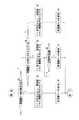
図7は本発明の実施の形態における発電機制御装置の動作を説明する図、図8は本発明の実施の形態における発電機制御部のブロック図、図9は本発明の実施の形態における発電機制御装置の動作を示すフローチャートである。
【0050】
図において、47は発電機制御装置、16は発電機であり、該発電機16としてDCブラシレス発電機が使用される。前記発電機16は、回転自在に配設されたロータ21(図2)、及び該ロータ21より径方向外方に配設されたステータ22を備える。前記ロータ21は、図示されないシャフトに図示されないハブを介して取り付けられた図示されないロータコア、及び該ロータコアの円周方向における複数箇所に配設された図示されない永久磁石を備える。また、前記ステータ22は、円周方向における複数箇所に、径方向内方に向けて突出させてステータポールが形成された図示されないステータコア、並びに前記ステータポールに巻装されたU相、V相及びW相のコイルとしてのステータコイル75〜77を備える。
【0051】
そして、前記発電機16を駆動してハイブリッド型車両を走行させるために、バッテリ43からの直流の電流がインバータ28によって各相の電流IGU、IGV、IGWに変換され、各相の電流IGU、IGV、IGWはそれぞれ各ステータコイル75〜77に供給される。
【0052】
そのために、前記インバータ28は、6個のスイッチング素子としてのトランジスタTr1〜Tr6を備え、各トランジスタTr1〜Tr6を選択的にオン・オフさせることによって、前記各相の電流IGU、IGV、IGWを発生させることができるようになっている。
【0053】
ところで、前記ステータコイル75〜77はスター結線されているので、各相のうちの二つの相の電流の値が決まると、残りの一つの相の電流の値も決まる。したがって、各相の電流IGU、IGV、IGWを制御するために、例えば、ステータコイル75、76のリード線にU相及びV相の電流IGU、IGVを検出する電流センサ66、67が配設され、該電流センサ66、67は、検出された電流IGU、IGVを電動機械制御部としての発電機制御部81に送る。
【0054】
該発電機制御部81には、図示されないCPUのほかに、データを記録したり、各種のプログラムを記録したりするための記録媒体としてのRAM、ROM等の図示されない記録装置が配設される。そして、前記RAMには、各種のプログラム、データ等が記録されるようになっているが、プログラム、データ等を同じ外部の記録媒体に記録することもできる。この場合、例えば、前記発電機制御部81にフラッシュメモリを配設し、前記外部の記録媒体から前記プログラム、データ等を読み出してフラッシュメモリに記録することもできる。したがって、外部の記録媒体を交換することによって、前記プログラム、データ等を更新することもできる。
【0055】
そして、車両制御装置51(図6)の前記発電機回転速度算出処理手段は、発電機制御部81の磁極位置算出処理手段としての磁極位置算出部82(図1)によって算出された発電機ロータ位置θGを読み込み、該発電機ロータ位置θGに基づいて発電機回転速度NGを算出する。また、車両制御装置51の図示されない指令値発生処理手段としての指令値発生部は、前記車速V、及びアクセルスイッチ55によって検出されたアクセルペダル位置APに基づいて車両要求トルクTO*を算出し、該車両要求トルクTO*に対応させて、発電機目標トルクTG*を発生させ、該発電機目標トルクTG*を前記発電機制御部81に送る。
【0056】
該発電機制御部81は図示されないメモリを備え、該メモリはd軸用及びq軸用の電流指令値マップを備える。そして、前記発電機制御部81の電流指令値発生処理手段としてのトルク指令・電流指令変換部101は、トルク指令・電流指令変換処理を行い、バッテリ電圧センサ72によって検出されたバッテリ電圧VB及び発電機回転速度NGを読み込み、前記各電流指令値マップを参照して、前記発電機目標トルクTG*に基づいてd軸電流指令値id*及びq軸電流指令値iq*を電流指令値として算出し、前記d軸電流指令値id*及びq軸電流指令値iq*を加算器102、103に送る。
【0057】
続いて、該d軸電流指令値id*及びq軸電流指令値iq*に、前記磁極位置θを算出するために、高周波電流Ih*が注入される。そのために、発電機制御部81に高周波電流発生処理手段としての高周波電流発生部104が配設され、該高周波電流発生部104に高周波電流制御信号SG3が送られる。該高周波電流制御信号SG3は、発電機制御部81の高周波電流注入停止処理手段としての高周波電流制御部86によって発生させられ、電動機械ブレーキ制御処理手段94によって発生させられた発電機ブレーキ係合要求に基づいて発電機16の高周波電流制御を開始する際にオンにされ、高周波電流制御を終了する際にオフにされる。
【0058】
そして、前記高周波電流制御信号SG3がオンになると、高周波電流発生部104は高周波電流Ih*を発生させ、加算器102、103に送り、該加算器102、103において、前記d軸電流指令値id*及びq軸電流指令値iq*に高周波電流Ih*が注入される。その結果、d軸電流指令値idh*及びq軸電流指令値iqh*が発生させられる。なお、前記加算器102、103によって高周波電流注入処理手段としての高周波電流注入部91が構成される。
【0059】
ところで、前記発電機制御部81においては、発電機16のロータ21の磁極対の方向にd軸を、該d軸と直角の方向にq軸をそれぞれ採ったd−q軸モデル上でベクトル制御演算によるフィードバック制御が行われるようになっている。
【0060】
そのために、前記発電機制御部81は、電流センサ66、67から電流IGU、IGVを読み込む。そして、発電機制御部81内の電流変換処理手段としてのUV−dq変換器105は、前記電流IGU、IGV及び前記発電機ロータ位置θGに基づいて三相/二相変換を行い、電流IGU、IGVをそれぞれd軸電流id及びq軸電流iqに変換する。
【0061】
そして、d軸電流idは減算器107に送られ、該減算器107においてd軸電流idと前記d軸電流指令値idh*とのd軸電流偏差Δidが算出され、該d軸電流偏差Δidが第1の電圧指令値発生処理手段としてのd軸電圧指令値発生部111に送られる。一方、q軸電流iqは減算器108に送られ、該減算器108においてq軸電流iqと前記q軸電流指令値iqh*とのq軸電流偏差Δiqが算出され、該q軸電流偏差Δiqが第2の電圧指令値発生処理手段としてのq軸電圧指令値発生部112に送られる。
【0062】
そして、前記d軸電圧指令値発生部111及びq軸電圧指令値発生部112は、前記d軸電流偏差Δid及びq軸電流偏差Δiqが零(0)になるように、2軸上のインバータ出力としてのd軸電圧指令値Vd*及びq軸電圧指令値Vq*をそれぞれ発生させ、該d軸電圧指令値Vd*及びq軸電圧指令値Vq*をそれぞれ電圧変換処理手段としてのdq−UV変換器113に送る。なお、前記d軸電圧指令値発生部111及びq軸電圧指令値発生部112によって電圧指令値発生処理手段としての電圧指令値発生部92が構成され、該電圧指令値発生部92は、前記d軸電流指令値idh*、q軸電流指令値iqh*及び電流IGU、IGVに基づいて、前記d軸電圧指令値Vd*及びq軸電圧指令値Vq*を電圧指令値として発生させる。
【0063】
続いて、前記dq−UV変換器113は、前記d軸電圧指令値Vd*、q軸電圧指令値Vq*及び発電機ロータ位置θGに基づいて二相/三相変換を行い、d軸電圧指令値Vd*及びq軸電圧指令値Vq*をU相、V相及びW相の電圧指令値Vu*、Vv*、Vw*に変換し、該電圧指令値Vu*、Vv*、Vw*をPWM発生処理手段としてのPWM発生器114に送る。該PWM発生器114は、前記各相の電圧指令値Vu*、Vv*、Vw*及び前記バッテリ電圧VBに基づいて、前記d軸電流指令値id*及びq軸電流指令値iq*に対応するパルス幅を有する各相のパルス幅変調信号Mu、Mv、Mwを発生させ、発電機制御装置47のインバータ駆動処理手段としてのドライブ回路85に送る。
【0064】
該ドライブ回路85は、前記各相のパルス幅変調信号Mu、Mv、Mwを受けて、トランジスタTr1〜Tr6を駆動するための6個の駆動信号SG1をそれぞれ発生させ、該駆動信号をインバータ28に送る。該インバータ28は、前記駆動信号SG1がオンの間だけトランジスタTr1〜Tr6をオンにして電流IGU、IGV、IGWを発生させ、該電流IGU、IGV、IGWを前記各ステータコイル75〜77に供給する。なお、Cは平滑用のコンデンサである。また、前記PWM発生器114、ドライブ回路85、インバータ28等によって、発電機16を駆動する電動機械駆動処理手段93が構成される。
【0065】
ところで、本実施の形態においては、レゾルバ等のセンサを使用することなく、発電機ロータ位置θGを算出するようになっている。そのために、前記d軸電圧指令値発生部111によって発生させられたd軸電圧指令値Vd*、及びq軸電圧指令値発生部112によって発生させられたq軸電圧指令値Vq*が電圧変量として磁極位置算出部82に送られるようになっている。
【0066】
そして、前記トルク指令・電流指令変換部101は、まず、所定の発電機ロータ位置θsを初期値として推定し、推定された発電機ロータ位置θsに基づいて推定d−q座標を想定し、該推定d−q座標において前記d軸電流指令値id*及びq軸電流指令値iq*を発生させ、加算器102、103に送る。続いて、加算器102、103において前記d軸電流指令値id*及びq軸電流指令値iq*に高周波電流Ih*が注入されるので、前記d軸電圧指令値Vd*及びq軸電圧指令値Vq*に高周波電圧が発生させられる。
【0067】
該高周波電圧が発生させられたd軸電圧指令値Vd*及びq軸電圧指令値Vq*には、d軸インダクタンスとq軸インダクタンスとの差による推定された磁極位置と実際の磁極位置との誤差情報が含まれるので、前記磁極位置算出部82は、d軸電圧指令値Vd*及びq軸電圧指令値Vq*を読み込み、バンドパスフィルタ、ローパスフィルタ等を通して前記誤差情報を取得し、該誤差情報が小さくなるように制御を行う。その結果、推定された発電機ロータ位置θsと実際の発電機ロータ位置θGとの差が小さくなり、収束して発電機ロータ位置θGが電気角で算出される。
【0068】
本実施の形態においては、d軸電流指令値id*及びq軸電流指令値iq*に高周波電流Ih*が注入されるようになっているが、d軸電流指令値id*及びq軸電流指令値iq*のうちのいずれか一方だけに高周波電流を注入し、発電機ロータ位置θGを算出することもできる。
【0069】
また、本実施の形態においては、電圧変量としてd軸電圧指令値Vd*及びq軸電圧指令値Vq*が使用されるが、電圧変量としては、d軸電圧指令値発生部111及びq軸電圧指令値発生部112と発電機16との間において発生する電圧に係る変量、例えば、dq−UV変換器113によって発生させられた各相の電圧指令値Vu*、Vv*、Vw*を使用したり、インバータ28を駆動することによってステータコイル75〜77に印加される電圧Vu、Vv、Vw等を使用したりすることができる。
【0070】
ところで、前述されたように、発電機ロータ位置θGを算出するために、d軸電流指令値id*及びq軸電流指令値iq*のうちの少なくとも一方に、常時、高周波電流が注入されるので、発電機16の制御が必要ない場合でも、本来ならば不必要である磁極位置を算出するために高周波電流が注入されることになり、限られた容量のバッテリ43の消費電力が大きくなり、ハイブリッド型車両の燃費が悪くなってしまう。
【0071】
そこで、前記高周波電流制御部86は、前記電動機械ブレーキ制御処理手段94によって発生させられた発電機ブレーキ係合要求があるかどうかを判断し、発電機ブレーキ係合要求がある場合、ゲート信号SG4をオフにして、前記PWM発生器114におけるパルス幅変調信号Mu、Mv、Mwの発生を停止させるとともに、高周波電流制御信号SG3をオフにして、d軸電流指令値id*及びq軸電流指令値iq*への高周波電流Ih*の注入を停止させる。続いて、前記電動機械ブレーキ制御処理手段94は、発電機ブレーキBを係合させる。
【0072】
また、前記発電機ブレーキ係合要求がない場合、すなわち、解除された場合、前記高周波電流制御部86は、発電機ブレーキBが係合させられているかどうかを判断し、発電機ブレーキBが係合させられている場合、ゲート信号SG4をオンにして、前記PWM発生器114におけるパルス幅変調信号Mu、Mv、Mwを発生させるとともに、高周波電流制御信号SG3をオンにして、d軸電流指令値id*及びq軸電流指令値iq*に高周波電流Ih*を注入する。そして、高周波電流Ih*の注入が開始された後、一定時間(例えば、50〔ms〕)が経過し、推定された発電機ロータ位置θsと実際の発電機ロータ位置θGとの差が小さくなり、収束すると、前記電動機械ブレーキ制御処理手段94は、発電機ブレーキBを解放する。このように、推定された発電機ロータ位置θsと実際の発電機ロータ位置θGとの差が小さくなり、収束したときに、発電機ブレーキBが解放されるので、発電機ロータ位置θGの算出精度を高くすることができる。
【0073】
また、発電機ブレーキBが係合させられている間、d軸電流指令値id*及びq軸電流指令値iq*への高周波電流Ih*の注入が停止させられるので、バッテリ43の消費電力を小さくすることができ、ハイブリッド型車両の燃費を良くすることができる。
【0074】
次に、フローチャートについて説明する。
ステップS1 発電機ブレーキ係合要求があるかどうかを判断する。発電機ブレーキ係合要求がある場合はステップS2に、ない場合はステップS4に進む。
ステップS2 ゲート信号SG4をオフにし、高周波電流制御信号SG3をオフにする。
ステップS3 発電機ブレーキBを係合させ、処理を終了する。
ステップS4 発電機ブレーキBが係合させられているかどうかを判断する。発電機ブレーキBが係合させられている場合はステップS5に、係合させられていない場合はステップS8に進む。
ステップS5 ゲート信号SG4をオフにし、高周波電流制御信号SG3をオンにする。
ステップS6 一定時間が経過するのを待機する。
ステップS7 発電機ブレーキBを解放し、処理を終了する。
ステップS8 ゲート信号SG4をオンにし、高周波電流制御信号SG3をオンにする。
ステップS9 発電機ブレーキBを解放し、処理を終了する。
【0075】
なお、本発明は前記実施の形態に限定されるものではなく、本発明の趣旨に基づいて種々変形させることが可能であり、それらを本発明の範囲から排除するものではない。
【0076】
【発明の効果】
以上詳細に説明したように、本発明によれば、電動機械駆動制御装置においては、電動機械と、該電動機械の回転を機械的に停止させる電動機械ブレーキと、電動機械トルクの目標値を表す電動機械目標トルクに基づいて電流指令値を発生させる電流指令値発生処理手段と、高周波電流を発生させる高周波電流発生処理手段と、前記電流指令値に高周波電流を注入する高周波電流注入処理手段と、高周波電流が注入された電流指令値、及び電動機械のコイルを流れる電流に基づいて電圧指令値を発生させる電圧指令値発生処理手段と、該電圧指令値発生処理手段によって発生させられた電圧指令値に基づいて前記電動機械を駆動する電動機械駆動処理手段と、前記電圧指令値発生処理手段と電動機械との間において発生させられた電圧変量を読み込み、該電圧変量に基づいて磁極位置を算出する磁極位置算出処理手段と、前記電動機械ブレーキを係合させるための電動機械ブレーキ係合要求を発生させる電動機械ブレーキ制御処理手段と、前記電動機械ブレーキ係合要求がある場合に、前記電流指令値への高周波電流の注入を停止させる高周波電流注入停止処理手段とを有する。
【0077】
この場合、電動機械ブレーキが係合させられている間、電流指令値への高周波電流の注入が停止させられるので、バッテリの消費電力を小さくすることができ、ハイブリッド型車両の燃費を良くすることができる。
【0078】
本発明の他の電動機械駆動制御装置においては、さらに、前記電動機械ブレーキ制御処理手段は、電動機械ブレーキ係合要求が解除された場合に、前記電流指令値への高周波電流の注入が開始された後、一定時間が経過したときに電動機械ブレーキを解放する。
【0079】
この場合、誤差情報が小さくなり、収束したときに、電動機械ブレーキが解放されるので、磁極位置の算出精度を高くすることができる。
【図面の簡単な説明】
【図1】本発明の実施の形態における発電機駆動制御装置の機能ブロック図である。
【図2】本発明の実施の形態におけるハイブリッド型車両の概念図である。
【図3】本発明の実施の形態におけるプラネタリギヤユニットの動作説明図である。
【図4】本発明の実施の形態における通常走行時の車速線図である。
【図5】本発明の実施の形態における通常走行時のトルク線図である。
【図6】本発明の実施の形態におけるハイブリッド型車両駆動制御装置を示す概念図である。
【図7】本発明の実施の形態における発電機制御装置の動作を説明する図である。
【図8】本発明の実施の形態における発電機制御部のブロック図である。
【図9】本発明の実施の形態における発電機制御装置の動作を示すフローチャートである。
【符号の説明】
16 発電機
21 ロータ
23 コイル
47 発電機制御装置
49 駆動モータ制御装置
51 車両制御装置
82 磁極位置算出部
86 高周波電流制御部
91 高周波電流注入部
92 電圧指令値発生部
93 電動機械駆動処理手段
94 電動機械ブレーキ制御処理手段
101 トルク指令・電流指令変換部
104 高周波電流発生部
B 発電機ブレーキ[0001]
BACKGROUND OF THE INVENTION
The present invention relates to an electric machine drive control device, an electric machine drive control method, and a program thereof.
[0002]
[Prior art]
Conventionally, for example, in a hybrid type vehicle in which a part of engine torque, that is, a part of engine torque is transmitted to a generator (generator motor) as an electric machine and the rest is transmitted to drive wheels, a sun gear, a ring gear and a carrier are used. A planetary gear unit including: the carrier and the engine; the ring gear and the drive wheel; the sun gear and the generator; and the rotation output from the ring gear and the drive motor as the drive wheel. The driving force is generated by transmitting.
[0003]
In this type of hybrid vehicle, the engine efficiency is extremely low in the region where the rotational speed is low, and the torque of the drive motor, that is, the drive motor torque is greater than the engine torque. Therefore, at the start, only the drive motor is driven, The drive of the engine is stopped and the hybrid vehicle is driven in the motor drive mode. At this time, the engine has sliding resistance, and the inertia is larger than that of the generator, so that the generator is swung without rotating the engine. After the start, when the vehicle speed reaches an engine start vehicle speed suitable for starting the engine, the engine speed, that is, the engine speed is increased to a speed suitable for ignition by driving the generator. Then, the engine is started, and then the drive motor and the engine are driven, and the hybrid type vehicle is driven in the motor / engine drive mode. Thereafter, the torque of the generator, that is, the generator torque is controlled, and a reaction force necessary to support the engine torque is generated.
[0004]
By the way, the generator is rotatably arranged, and includes a rotor having an N-pole and S-pole magnetic pole pair, and is arranged radially outward from the rotor, and is a U-phase, V-phase, and W-phase stator. A generator including a stator having a coil, and supplying a U-phase, a V-phase, and a W-phase current to the stator coil by a generator control device as an electric machine control device, and applying a predetermined voltage; The machine is driven and generator torque is generated.
[0005]
In the generator control device, the current supplied to the stator coil is detected as a detected current by a current sensor, and the position of the magnetic pole of the rotor, that is, the position of the magnetic pole is detected as a detected magnetic pole position by a resolver. The current and the detected magnetic pole position are sent to the generator controller. The generator control unit drives the inverter based on the detected current, the detected magnetic pole position, and the generator target torque (torque command value) representing the target value of the generator torque sent from the vehicle control circuit.
[0006]
Therefore, in the generator control unit, feedback control by vector control calculation is performed on a dq axis model in which the d axis is taken in the direction of the magnetic pole pair of the rotor and the q axis is taken in a direction perpendicular to the d axis. A d-axis current command value and a q-axis current command value are generated based on the generator target torque, and a d-axis voltage command value and a q-axis current command value are generated based on the d-axis current command value and the q-axis current command value. A shaft voltage command value is generated.
[0007]
However, if the resolver is used, the detection accuracy of the magnetic pole position and the controllability of the generator can be improved, but the cost of the generator control device is increased. Therefore, a magnetic pole position calculation method is provided in which the magnetic pole position is calculated without using a sensor such as the resolver.
[0008]
In the magnetic pole position calculation method, first, a predetermined magnetic pole position is estimated as an initial value, an estimated dq coordinate is assumed based on the estimated magnetic pole position, and a d-axis current command value is calculated in the estimated dq coordinate. And q-axis current command value is generated. Subsequently, by injecting a high frequency current into at least one of the d axis current command value and the q axis current command value, a high frequency voltage is generated in the d axis voltage command value and the q axis voltage command value. In this case, in the d-axis voltage command value and the q-axis voltage command value in which the high-frequency voltage is generated, error information between the estimated magnetic pole position and the actual magnetic pole position due to the difference between the d-axis inductance and the q-axis inductance is included. Is included. When control is performed to reduce the error information, the difference between the estimated magnetic pole position and the actual magnetic pole position disappears, and the magnetic pole position is calculated as an electrical angle.
[0009]
[Problems to be solved by the invention]
However, in the conventional generator control device, since the high-frequency current is always injected into at least one of the d-axis current command value and the q-axis current command value, the d-axis current command value and the q-axis current command When the value is zero (0), that is, even when the generator is not required to be controlled, a high-frequency current is injected in order to calculate a magnetic pole position that is originally unnecessary. The power consumption of the battery is increased, and the fuel efficiency of the hybrid vehicle is deteriorated.
[0010]
The present invention solves the problems of the conventional generator control device, reduces the power consumption of the battery, and improves the fuel efficiency of the hybrid vehicle, and the electric machine drive control device and the electric machine drive It is an object to provide a control method and its program.
[0011]
[Means for Solving the Problems]
Therefore, in the electric machine drive control device of the present invention, the electric machine, the electric machine brake that mechanically stops the rotation of the electric machine, and the electric machine current based on the electric machine target torque that represents the target value of the electric machine torque. Current command value generation processing means for generating a command value, high frequency current generation processing means for generating a high frequency current, high frequency current injection processing means for injecting a high frequency current into the current command value, and a current command in which the high frequency current is injected Voltage command value generation processing means for generating a voltage command value based on the value and current flowing through the coil of the electric machine, and driving the electric machine based on the voltage command value generated by the voltage command value generation processing means Electric machine drive processing means, and a voltage variable generated between the voltage command value generation processing means and the electric machine is read, and the voltage variable There are magnetic pole position calculation processing means for calculating the magnetic pole position, electric machine brake control processing means for generating an electric machine brake engagement request for engaging the electric machine brake, and the electric machine brake engagement request. A high-frequency current injection stop processing means for stopping high-frequency current injection to the current command value.
[0012]
In another electric machine drive control device of the present invention, the voltage variable is the voltage command value.
[0013]
In still another electric machine drive control device of the present invention, the electric machine brake control processing means starts injecting a high-frequency current into the current command value when the electric machine brake engagement request is released. After that, the electric machine brake is released when a certain time has passed.
[0014]
In still another electric machine drive control device of the present invention, the electric machine is mechanically coupled to the engine so as to be differentially rotatable.
[0015]
In still another electric machine drive control device according to the present invention, the electric machine, the engine, and the other electric machine are connected via a planetary gear unit.
[0016]
In the electric machine drive control method of the present invention, a current command value is generated based on the electric machine target torque representing the target value of the electric machine torque, a high frequency current is generated, and the high frequency current is injected into the current command value, A voltage command value is generated based on the current command value into which the high-frequency current is injected and the current flowing through the coil of the electric machine, and the electric machine is driven based on the voltage command value. The voltage variable generated during the period is read, the magnetic pole position is calculated based on the voltage variable, the electric machine brake engagement request for engaging the electric machine brake is generated, and the electric machine brake engagement request When there is, the injection of the high frequency current to the current command value is stopped.
[0017]
In the electric machine drive control method program of the present invention, the computer causes the current command value generation processing means for generating the current command value based on the electric machine target torque representing the target value of the electric machine torque, and the high frequency for generating the high frequency current. Current generation processing means, high-frequency current injection processing means for injecting a high-frequency current into the current command value, a current command value into which the high-frequency current has been injected, and a voltage command for generating a voltage command value based on the current flowing through the coil of the electric machine Value generation processing means, electric machine drive processing means for driving the electric machine based on the voltage command value generated by the voltage command value generation processing means, and generated between the voltage command value generation means and the electric machine. A magnetic pole position calculation processing means for reading the received voltage variable and calculating a magnetic pole position based on the voltage variable; An electromechanical brake control processing means for generating an electromechanical brake engagement request for matching, and a high frequency current injection stop for stopping injection of a high frequency current to the current command value when there is an electromechanical brake engagement request It functions as a processing means.
[0018]
DETAILED DESCRIPTION OF THE INVENTION
Hereinafter, embodiments of the present invention will be described in detail with reference to the drawings. In addition, the generator drive control apparatus as an electric machine drive control apparatus is demonstrated.
[0019]
FIG. 1 is a functional block diagram of a generator drive control device according to an embodiment of the present invention.
[0020]
In the figure, 16 is a generator as a first electric machine, B is a generator brake as an electric machine brake that mechanically stops the rotation of the
[0021]
FIG. 2 is a conceptual diagram of a hybrid vehicle according to the embodiment of the present invention.
[0022]
In the figure, 11 is an engine (E / G) disposed on the first axis, 12 is disposed on the first axis, and outputs the rotation generated by driving the
[0023]
The output shaft 14 has a sleeve shape and is disposed so as to surround the
[0024]
The
[0025]
Further, the
[0026]
[0027]
The
[0028]
In order to rotate the
[0029]
A differential device 36 is disposed on a fourth axis parallel to the first to third axes, and the
[0030]
Next, the operation of the
[0031]
FIG. 3 is a diagram for explaining the operation of the planetary gear unit according to the embodiment of the present invention, FIG. 4 is a vehicle speed diagram during normal traveling according to the embodiment of the present invention, and FIG. 5 is a torque during normal traveling according to the embodiment of the present invention. FIG.
[0032]
In the planetary gear unit 13 (FIG. 2), the carrier CR is connected to the
(Ρ + 1) ・ NE = 1 ・ NG + ρ ・ NR
The relationship is established. Therefore, the engine rotational speed NE is based on the ring gear rotational speed NR and the generator rotational speed NG.
NE = (1 · NG + ρ · NR) / (ρ + 1) (1)
Can be calculated. In addition, the rotational speed relational expression of the
[0033]
Further, the engine torque TE, the torque generated in the ring gear R, that is, the ring gear torque TR, and the generator torque TG as the electric machine torque are:
TE: TR: TG = (ρ + 1): ρ: 1 (2)
And receive reaction forces from each other. In addition, the torque relational expression of the
[0034]
During normal driving of the hybrid type vehicle, the ring gear R, the carrier CR, and the sun gear S are all rotated in the forward direction, and as shown in FIG. 4, the ring gear rotation speed NR, the engine rotation speed NE, and the generator rotation. The speed NG is a positive value. Further, the ring gear torque TR and the generator torque TG are obtained by dividing the engine torque TE by a torque ratio determined by the number of teeth of the
[0035]
Next, a hybrid type vehicle drive apparatus for driving the hybrid type vehicle having the above configuration and a hybrid type vehicle drive control apparatus for controlling the hybrid type vehicle drive apparatus will be described.
[0036]
FIG. 6 is a conceptual diagram showing a hybrid type vehicle drive control device according to the embodiment of the present invention.
[0037]
In the figure, 10 is a case, 11 is an engine, 13 is a planetary gear unit, 16 is a generator, B is a generator brake for fixing the
[0038]
Reference numeral 51 denotes a vehicle control device that includes a CPU, a recording device, and the like (not shown), functions as a computer, and controls the entire hybrid vehicle. The vehicle control device 51 includes an
[0039]
The
[0040]
The inverter 29 is driven based on the drive signal SG2, receives a direct current from the
[0041]
44 is a battery remaining amount detection device that detects the state of the
[0042]
[0043]
The vehicle control device 51 sends an engine control signal to the
[0044]
Further, the vehicle control device 51 calculates the engine rotational speed NE by the rotational speed relational expression, and the engine control rotational speed NE that represents the target value of the engine rotational speed NE to the
[0045]
In the present embodiment, the engine speed NE is calculated by the vehicle control device 51. However, the engine speed NE can also be read from the
[0046]
By the way, after starting the hybrid vehicle, when the vehicle speed reaches an engine start vehicle speed suitable for starting the
[0047]
Further, when the hybrid vehicle is running with the generator brake B engaged, the generator brake B is released if the
[0048]
By the way, in the hybrid vehicle drive control device having the above-described configuration, the generator rotor position θG and the drive motor rotor position θM are calculated without using a sensor such as a resolver. Next, the operation of the
[0049]
FIG. 7 is a diagram for explaining the operation of the generator control device according to the embodiment of the present invention, FIG. 8 is a block diagram of a generator control unit according to the embodiment of the present invention, and FIG. 9 is a power generation according to the embodiment of the present invention. It is a flowchart which shows operation | movement of a machine control apparatus.
[0050]
In the figure, 47 is a generator control device and 16 is a generator, and a DC brushless generator is used as the
[0051]
And in order to drive the said
[0052]
Therefore, the
[0053]
By the way, since the stator coils 75 to 77 are star-connected, when the current values of two phases of each phase are determined, the current values of the remaining one phase are also determined. Therefore, in order to control the currents IGU, IGV, and IGW of each phase, for example,
[0054]
In addition to a CPU (not shown), the
[0055]
The generator rotation speed calculation processing means of the vehicle control device 51 (FIG. 6) is the generator rotor calculated by the magnetic pole position calculation unit 82 (FIG. 1) as the magnetic pole position calculation processing means of the
[0056]
The
[0057]
Subsequently, the d-axis current command value id* And q-axis current command value iq* In order to calculate the magnetic pole position θ, the high-frequency current Ih* Is injected. For this purpose, the
[0058]
When the high-frequency current control signal SG3 is turned on, the high-frequency
[0059]
By the way, the
[0060]
For this purpose, the
[0061]
The d-axis current id is sent to the
[0062]
The d-axis voltage command
[0063]
Subsequently, the dq-
[0064]
The drive circuit 85 receives the pulse width modulation signals Mu, Mv, and Mw of the respective phases, generates six drive signals SG1 for driving the transistors Tr1 to Tr6, and supplies the drive signals to the
[0065]
By the way, in the present embodiment, the generator rotor position θG is calculated without using a sensor such as a resolver. For this purpose, the d-axis voltage command value Vd generated by the d-axis voltage
[0066]
The torque command / current
[0067]
D-axis voltage command value Vd from which the high-frequency voltage is generated* And q-axis voltage command value Vq* Includes error information between the magnetic pole position estimated based on the difference between the d-axis inductance and the q-axis inductance and the actual magnetic pole position, the magnetic pole
[0068]
In the present embodiment, the d-axis current command value id* And q-axis current command value iq* High frequency current Ih* D-axis current command value id* And q-axis current command value iq* It is also possible to calculate the generator rotor position θG by injecting a high-frequency current into only one of them.
[0069]
In the present embodiment, the d-axis voltage command value Vd is used as the voltage variable.* And q-axis voltage command value Vq* As the voltage variable, a variable relating to a voltage generated between the d-axis voltage command
[0070]
Incidentally, as described above, in order to calculate the generator rotor position θG, the d-axis current command value id* And q-axis current command value iq* Since a high frequency current is always injected into at least one of them, even when the control of the
[0071]
Therefore, the high-frequency
[0072]
When the generator brake engagement request is not issued, that is, when the generator brake B is released, the high frequency
[0073]
While the generator brake B is engaged, the d-axis current command value id* And q-axis current command value iq* High frequency current Ih to* Therefore, the power consumption of the
[0074]
Next, a flowchart will be described.
Step S1: It is determined whether there is a generator brake engagement request. If there is a generator brake engagement request, the process proceeds to step S2, and if not, the process proceeds to step S4.
Step S2: The gate signal SG4 is turned off and the high-frequency current control signal SG3 is turned off.
Step S3: The generator brake B is engaged, and the process is terminated.
Step S4: Determine whether the generator brake B is engaged. When the generator brake B is engaged, the process proceeds to step S5, and when not engaged, the process proceeds to step S8.
Step S5: The gate signal SG4 is turned off and the high-frequency current control signal SG3 is turned on.
Step S6 Wait for a certain time to elapse.
Step S7: The generator brake B is released and the process is terminated.
Step S8: The gate signal SG4 is turned on and the high frequency current control signal SG3 is turned on.
Step S9: The generator brake B is released and the process is terminated.
[0075]
In addition, this invention is not limited to the said embodiment, It can change variously based on the meaning of this invention, and does not exclude them from the scope of the present invention.
[0076]
【The invention's effect】
As described above in detail, according to the present invention, the electric machine drive control device represents the electric machine, the electric machine brake that mechanically stops the rotation of the electric machine, and the target value of the electric machine torque. Current command value generation processing means for generating a current command value based on the electric machine target torque, high frequency current generation processing means for generating a high frequency current, high frequency current injection processing means for injecting a high frequency current into the current command value, Voltage command value generation processing means for generating a voltage command value based on a current command value injected with a high-frequency current and a current flowing through a coil of an electric machine, and a voltage command value generated by the voltage command value generation processing means An electric machine drive processing means for driving the electric machine based on the voltage, and a voltage variable generated between the voltage command value generation processing means and the electric machine. Magnetic pole position calculation processing means for calculating a magnetic pole position based on the voltage variable, electric machine brake control processing means for generating an electric machine brake engagement request for engaging the electric machine brake, and the electric High frequency current injection stop processing means for stopping high frequency current injection to the current command value when there is a mechanical brake engagement request.
[0077]
In this case, since the injection of the high-frequency current into the current command value is stopped while the electromechanical brake is engaged, the power consumption of the battery can be reduced and the fuel efficiency of the hybrid vehicle can be improved. Can do.
[0078]
In another electric machine drive control device of the present invention, the electric machine brake control processing means starts injection of a high-frequency current into the current command value when the electric machine brake engagement request is released. After a certain period of time, the electromechanical brake is released.
[0079]
In this case, when the error information becomes small and converges, the electric mechanical brake is released, so that the calculation accuracy of the magnetic pole position can be increased.
[Brief description of the drawings]
FIG. 1 is a functional block diagram of a generator drive control device according to an embodiment of the present invention.
FIG. 2 is a conceptual diagram of a hybrid vehicle according to an embodiment of the present invention.
FIG. 3 is an operation explanatory diagram of the planetary gear unit in the embodiment of the present invention.
FIG. 4 is a vehicle speed diagram during normal traveling in the embodiment of the present invention.
FIG. 5 is a torque diagram during normal running in the embodiment of the present invention.
FIG. 6 is a conceptual diagram showing a hybrid vehicle drive control device according to an embodiment of the present invention.
FIG. 7 is a diagram for explaining the operation of the generator control device according to the embodiment of the present invention.
FIG. 8 is a block diagram of a generator control unit in the embodiment of the present invention.
FIG. 9 is a flowchart showing the operation of the generator control device according to the embodiment of the present invention.
[Explanation of symbols]
16 Generator
21 Rotor
23 Coil
47 Generator control device
49 Drive motor controller
51 Vehicle control device
82 Magnetic pole position calculator
86 High-frequency current controller
91 High-frequency current injection part
92 Voltage command value generator
93 Electric machine drive processing means
94 Electric machine brake control processing means
101 Torque command / current command converter
104 High frequency current generator
B Generator brake
Claims (7)
Translated fromJapanesePriority Applications (1)
| Application Number | Priority Date | Filing Date | Title |
|---|---|---|---|
| JP2001199918AJP4240852B2 (en) | 2001-06-29 | 2001-06-29 | Electric machine drive control device, electric machine drive control method, and program thereof |
Applications Claiming Priority (1)
| Application Number | Priority Date | Filing Date | Title |
|---|---|---|---|
| JP2001199918AJP4240852B2 (en) | 2001-06-29 | 2001-06-29 | Electric machine drive control device, electric machine drive control method, and program thereof |
Publications (2)
| Publication Number | Publication Date |
|---|---|
| JP2003018704A JP2003018704A (en) | 2003-01-17 |
| JP4240852B2true JP4240852B2 (en) | 2009-03-18 |
Family
ID=19037130
Family Applications (1)
| Application Number | Title | Priority Date | Filing Date |
|---|---|---|---|
| JP2001199918AExpired - Fee RelatedJP4240852B2 (en) | 2001-06-29 | 2001-06-29 | Electric machine drive control device, electric machine drive control method, and program thereof |
Country Status (1)
| Country | Link |
|---|---|
| JP (1) | JP4240852B2 (en) |
Families Citing this family (14)
| Publication number | Priority date | Publication date | Assignee | Title |
|---|---|---|---|---|
| JP4684691B2 (en)* | 2005-03-16 | 2011-05-18 | 本田技研工業株式会社 | Brushless DC motor control device |
| US8358098B2 (en) | 2009-08-10 | 2013-01-22 | Emerson Climate Technologies, Inc. | System and method for power factor correction |
| US8493014B2 (en) | 2009-08-10 | 2013-07-23 | Emerson Climate Technologies, Inc. | Controller and method for estimating, managing, and diagnosing motor parameters |
| US8344706B2 (en) | 2009-08-10 | 2013-01-01 | Emerson Climate Technologies, Inc. | System and method for rejecting DC current in power factor correction systems |
| US8698433B2 (en)* | 2009-08-10 | 2014-04-15 | Emerson Climate Technologies, Inc. | Controller and method for minimizing phase advance current |
| US8264192B2 (en) | 2009-08-10 | 2012-09-11 | Emerson Climate Technologies, Inc. | Controller and method for transitioning between control angles |
| US8508166B2 (en) | 2009-08-10 | 2013-08-13 | Emerson Climate Technologies, Inc. | Power factor correction with variable bus voltage |
| US8476873B2 (en) | 2009-08-10 | 2013-07-02 | Emerson Climate Technologies, Inc. | System and method for current balancing |
| US8406021B2 (en) | 2009-08-10 | 2013-03-26 | Emerson Climate Technologies, Inc. | System and method for reducing line current distortion |
| US8264860B2 (en) | 2009-08-10 | 2012-09-11 | Emerson Climate Technologies, Inc. | System and method for power factor correction frequency tracking and reference generation |
| US9634593B2 (en) | 2012-04-26 | 2017-04-25 | Emerson Climate Technologies, Inc. | System and method for permanent magnet motor control |
| US9240749B2 (en) | 2012-08-10 | 2016-01-19 | Emerson Climate Technologies, Inc. | Motor drive control using pulse-width modulation pulse skipping |
| JP6137135B2 (en)* | 2014-11-20 | 2017-05-31 | トヨタ自動車株式会社 | Vehicle drive control device |
| JP7545323B2 (en) | 2020-12-28 | 2024-09-04 | カワサキモータース株式会社 | Vehicle control program and vehicle control device |
- 2001
- 2001-06-29JPJP2001199918Apatent/JP4240852B2/ennot_activeExpired - Fee Related
Also Published As
| Publication number | Publication date |
|---|---|
| JP2003018704A (en) | 2003-01-17 |
Similar Documents
| Publication | Publication Date | Title |
|---|---|---|
| JP4158363B2 (en) | Hybrid vehicle drive control device | |
| JP4147756B2 (en) | Electric vehicle drive control device, electric vehicle drive control method, and program | |
| CN101351959B (en) | Feedback control method and device for electric motor | |
| JP4239538B2 (en) | Electric machine control device, electric machine control method and program | |
| JP4240852B2 (en) | Electric machine drive control device, electric machine drive control method, and program thereof | |
| JP2004364453A (en) | Drive control device and method for motor vehicle, and its program | |
| JP2008048540A (en) | Method and device for controlling driving of electric motor | |
| JP2004215320A (en) | Apparatus and method for motor operated drive controlling and its program | |
| JP2005261125A (en) | Electric vehicle drive control device, electric vehicle drive control method, and program thereof | |
| JP3934130B2 (en) | Motor controller for hybrid vehicle | |
| JP4801548B2 (en) | Vehicle equipped with a rotating electrical machine for vehicles | |
| JP2005117861A (en) | Discharge control device, discharge control method and program thereof | |
| JP3985550B2 (en) | Electric vehicle drive control device, electric vehicle drive control method, and program thereof | |
| JP4232421B2 (en) | Electric machine control device, electric machine control method and program | |
| JP4438255B2 (en) | Motor control device, motor control method and program | |
| JP3873698B2 (en) | Hybrid vehicle drive control apparatus, hybrid vehicle drive control method, and program thereof | |
| JP4281316B2 (en) | Electric machine control device, electric machine control method and program | |
| JP2005057817A (en) | Motor drive controller, motor drive controlling method, and its program | |
| JP3933108B2 (en) | Electric drive control device, electric drive control method and program thereof | |
| JP4839119B2 (en) | Electric drive control device and electric drive control method | |
| JP4284901B2 (en) | Electric vehicle drive control device, electric vehicle drive control method, and program | |
| JP4232420B2 (en) | Electric machine control device, electric machine control method and program | |
| JP4039010B2 (en) | Hybrid vehicle drive control apparatus, hybrid vehicle drive control method, and program thereof | |
| JP4123728B2 (en) | Hybrid vehicle and control method thereof | |
| JP3988459B2 (en) | Hybrid vehicle drive control apparatus, hybrid vehicle drive control method, and program thereof |
Legal Events
| Date | Code | Title | Description |
|---|---|---|---|
| A621 | Written request for application examination | Free format text:JAPANESE INTERMEDIATE CODE: A621 Effective date:20060410 | |
| TRDD | Decision of grant or rejection written | ||
| A01 | Written decision to grant a patent or to grant a registration (utility model) | Free format text:JAPANESE INTERMEDIATE CODE: A01 Effective date:20081209 | |
| A01 | Written decision to grant a patent or to grant a registration (utility model) | Free format text:JAPANESE INTERMEDIATE CODE: A01 | |
| A61 | First payment of annual fees (during grant procedure) | Free format text:JAPANESE INTERMEDIATE CODE: A61 Effective date:20081222 | |
| FPAY | Renewal fee payment (event date is renewal date of database) | Free format text:PAYMENT UNTIL: 20120109 Year of fee payment:3 | |
| R150 | Certificate of patent or registration of utility model | Free format text:JAPANESE INTERMEDIATE CODE: R150 | |
| FPAY | Renewal fee payment (event date is renewal date of database) | Free format text:PAYMENT UNTIL: 20130109 Year of fee payment:4 | |
| FPAY | Renewal fee payment (event date is renewal date of database) | Free format text:PAYMENT UNTIL: 20140109 Year of fee payment:5 | |
| LAPS | Cancellation because of no payment of annual fees |