JP4237559B2 - Electronics - Google Patents
ElectronicsDownload PDFInfo
- Publication number
- JP4237559B2 JP4237559B2JP2003187030AJP2003187030AJP4237559B2JP 4237559 B2JP4237559 B2JP 4237559B2JP 2003187030 AJP2003187030 AJP 2003187030AJP 2003187030 AJP2003187030 AJP 2003187030AJP 4237559 B2JP4237559 B2JP 4237559B2
- Authority
- JP
- Japan
- Prior art keywords
- light guide
- light
- light emitting
- holder
- component mounting
- Prior art date
- Legal status (The legal status is an assumption and is not a legal conclusion. Google has not performed a legal analysis and makes no representation as to the accuracy of the status listed.)
- Expired - Fee Related
Links
Images


Classifications
- G—PHYSICS
- G06—COMPUTING OR CALCULATING; COUNTING
- G06F—ELECTRIC DIGITAL DATA PROCESSING
- G06F1/00—Details not covered by groups G06F3/00 - G06F13/00 and G06F21/00
- G06F1/16—Constructional details or arrangements
- G06F1/1613—Constructional details or arrangements for portable computers
- G06F1/1615—Constructional details or arrangements for portable computers with several enclosures having relative motions, each enclosure supporting at least one I/O or computing function
- G06F1/1616—Constructional details or arrangements for portable computers with several enclosures having relative motions, each enclosure supporting at least one I/O or computing function with folding flat displays, e.g. laptop computers or notebooks having a clamshell configuration, with body parts pivoting to an open position around an axis parallel to the plane they define in closed position
- G—PHYSICS
- G06—COMPUTING OR CALCULATING; COUNTING
- G06F—ELECTRIC DIGITAL DATA PROCESSING
- G06F1/00—Details not covered by groups G06F3/00 - G06F13/00 and G06F21/00
- G06F1/16—Constructional details or arrangements
- G06F1/1613—Constructional details or arrangements for portable computers
- G06F1/1633—Constructional details or arrangements of portable computers not specific to the type of enclosures covered by groups G06F1/1615 - G06F1/1626
- G06F1/1656—Details related to functional adaptations of the enclosure, e.g. to provide protection against EMI, shock, water, or to host detachable peripherals like a mouse or removable expansions units like PCMCIA cards, or to provide access to internal components for maintenance or to removable storage supports like CDs or DVDs, or to mechanically mount accessories
Landscapes
- Engineering & Computer Science (AREA)
- Computer Hardware Design (AREA)
- Theoretical Computer Science (AREA)
- General Engineering & Computer Science (AREA)
- Physics & Mathematics (AREA)
- Human Computer Interaction (AREA)
- General Physics & Mathematics (AREA)
- Mathematical Physics (AREA)
- Optical Couplings Of Light Guides (AREA)
- Non-Portable Lighting Devices Or Systems Thereof (AREA)
- Mounting Components In General For Electric Apparatus (AREA)
- Led Device Packages (AREA)
Description
Translated fromJapanese【0001】
【発明の属する技術分野】
この発明は、例えば、ポータブルコンピュータ等の電子機器に関する。
【0002】
【従来の技術】
例えば、ポータブルコンピュータ等の電子機器においては、コンピュータ本体の内底部にメインプリント基板を設け、このメインプリント基板の上部にキーボードを配置し、このキーボードをトップカバーとしてのキーボードホルダによってコンピュータ本体に固定している。また、コンピュータ本体にはヒンジによってディスプレイユニットを有するディスプレイハウジングが開閉自在に枢支されている。
【0003】
また、コンピュータ本体の内部にはサブプリント基板が設けられ、このサブプリント基板にはキーボードの制御キーに関する表示をなすアイコンの光源となる複数個の発光ダイオード(LED)を取付けられている。コンピュータ本体の上部にはキーボードを保持するキーボードホルダが設けられ、このキーボードホルダには電源スイッチのオン・オフ等を表示する表示部が設けられ、この表示部にはレンズが設けられている。
【0004】
また、サブプリント基板の発光ダイオードとレンズとは上下方向に離間しているために、発光ダイオードとレンズとの間には、発光ダイオードの光をレンズに導くために透明プラスチックからなる導光体が配置されている。従って、発光ダイオードが発光すると、光は導光体を介してレンズに導かれ、キーボードホルダの上面の表示部が光るようになっている(例えば、特許文献1及び2参照)。
【0005】
また、導光体は、各種部品を搭載するプラスチックからなるホルダに設けられているが、導光体とホルダとは別部材である。そして、このホルダにはプリント基板上の電源スイッチとコンピュータ本体の上部に設けられた電源ボタンを中継するための構造体、サブプリント基板を取付けるための台座及びコンピュータ本体の上部から下部へハーネスを挿通する挿通部が一体に設けられている。
【0006】
さらに、キーボードホルダにスピーカボックスを備え、テレビの音声を発生させたり、コンパクトディスクをセットして音声を再生して楽しむことができるものも普及している。さらに、電子メールを受信したことを表示したり、音響を楽しむ際に、そのタイトルを表示したり、さらにコンピュータの起動時にアプリケーションを表示することができるようになっている。
【0007】
一方、ポータブルコンピュータは、携帯に便利なように、筐体の薄型化、軽量化のため、筐体の内部には各種電子部品が密集して配置されており、外部入出力コネクタ等も限られたスペースに配置されている一方で、コネクタは、こじり等に対する耐性が要求されている。
【0008】
【特許文献1】
特許第3382073号公報 (図17及び明細書の[0194]〜[0196])
【0009】
【特許文献2】
特開平8−6670号公報 (図3及び明細書の[0176]〜[0177])
【0010】
【発明が解決しようとする課題】
ところで、前述のように構成されたポータブルコンピュータによると、発光ダイオードはメインプリント基板とは別部材のサブプリント基板に設けられているため、構造的に複雑となっている。
また、基板の各種部品を搭載するためのホルダと、発光ダイオードの光をキーボードホルダに設けられたレンズに導く導光体とは別部材である。しかも、ホルダには前記各種部品が密集して取付けられる。従って、部品点数が多く、また導光体をホルダに取付けるための工数がかかり、コストアップの原因となっている。
【0011】
この発明は、前記事情に着目してなされたもので、その目的とするところは、部品を搭載するためのホルダと、発光部の光を導く導光体とを一体とし、部品点数及び組立て工数の削減によりコストダウンを図ることができる電子機器を提供することにある。
【0012】
【課題を解決するための手段】
前記目的を達成するため、本発明の一つの形態に係る電子機器は、
機器本体と、前記機器本体内に設けられた発光部と、前記機器本体内に設けられ、部品を搭載する少なくとも一つの取付け部を有する透明な部品搭載ホルダと、前記発光部からの光を前記機器本体上に導く導光体と、を備えている。
前記部品搭載ホルダは、(1)前記導光体が貫通する孔と、(2)前記孔の内側面と前記導光体との間を連結して、前記導光体を前記孔の内部に保持するブリッジ状の結合部と、を有し、前記導光体および前記結合部が前記部品搭載ホルダと一体に成形されていることを特徴としている。
【0013】
前記構成によれば、部品を搭載するためのホルダと、発光部の光を導く導光体とを一体とし、部品点数及び組立て工数の削減によりコストダウンを図ることができる。
【0014】
【発明の実施の形態】
以下、この発明の実施の形態を図面に基づいて説明する。
【0015】
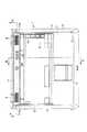
図1〜図9は第1の実施形態を示し、図1は電子機器としてのポータブルコンピュータのディスプレイハウジングを開いた状態の斜視図、図2はキーボードの一部を省略したコンピュータ本体の平面図である。図1及び図2に示すように、ポータブルコンピュータ1は、機器本体としてのコンピュータ本体2と、このコンピュータ本体2にヒンジ3によって回動可能に支持されたディスプレイユニット4とから構成されている。コンピュータ本体2は、扁平な箱状の筐体5を有しており、この筐体5は、上部開口の角皿状のベース6と、このベース6の上部開口を覆う平板状のカバー7とから構成されている。
【0016】
カバー7の上面にはパームレスト8、キーボード取付け部9が設けられ、キーボード取付け部9にはキーボード10が設けられている。キーボード10は、トップカバーとしてのキーボードホルダ11によってカバー7に固定されている。このキーボードホルダ11にスピーカボックス11aが左右対称的に設置されている。
【0017】
また、図6に示すように、コンピュータ本体2のヒンジ3側における側部には複数の外部入出力コネクタ12が設置されており、これら外部入出力コネクタ12相互間には隙間12aが設けられている。
【0018】
図3〜図5に示すように、ベース6の内底部には回路基板としてのメインプリント基板13が設けられている。メインプリント基板13の一部、すなわち、コンピュータ本体2のヒンジ3に偏倚した位置には電源スイッチ14が実装されている。さらに、メインプリント基板13には電源スイッチ14と隣接してアイコンの光源となる複数個、本実施形態では4個の発光部としての発光ダイオード15が等間隔に一列に実装されている。また、メインプリント基板13には発光ダイオード15と隣接してフレキシブルコード用コネクタ16が実装されている。
【0019】
さらに、メインプリント基板13の上部にはメインプリント基板13に実装された電源スイッチ14、発光ダイオード15及びフレキシブルコード用コネクタ16等に対応して部品搭載ホルダ17が設けられている。この部品搭載ホルダ17には複数の取付け孔(図示しない)が設けられ、これら取付け孔には固定ねじ18が挿通され、部品搭載ホルダ17はメインプリント基板13に対して固定されている。
【0020】
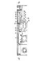
部品搭載ホルダ17は、図7〜図9に示すように、透明プラスチックによって一体に形成されており、一端部側には電源スイッチ14と対向するボタン取付け部19が、中間部には発光ダイオード15と対向する導光体取付け部20が、さらに他端部側にはフレキシブルコード用コネクタ16と対向して台座としてのサブプリント基板取付け部21が設けられている。
【0021】
まず、部品搭載ホルダ17に設けられたボタン取付け部19について説明すると、部品搭載ホルダ17の上面には構造体としての上部開口の矩形状の囲い壁22が一端に設けられ、この外周壁には補強リブ23が設けられている。さらに、囲い壁22に囲まれた底部24には透孔25が設けられている。囲い壁22には押しボタン式の電源ボタン26が上下動自在に収納され、この電源ボタン26は透孔25を貫通する操作軸27を介して電源スイッチ14に連結されている。
【0022】
電源ボタン26の上面にはボタン操作部28が設けられ、このボタン操作部28はキーボードホルダ11に設けられた開口部29から上面に露出している。従って、ボタン操作部28を押しボタン式に操作することにより、電源スイッチ14をオン・オフできるようになっている。
【0023】
次に、部品搭載ホルダ17に設けられた導光体取付け部20について説明すると、4個一列の発光ダイオード15に対向して長孔30が設けられている。この長孔30には部品搭載ホルダ17と一体で、かつ4個の発光ダイオード15に対向して導光体31が設けられている。これら導光体31は上部に向かって先細の円柱形状であり、基端大径部31aは発光ダイオード15に接近し、上端小径部31bはキーボードホルダ11に発光ダイオード15と対応して設けられたレンズ32と接触して設けられている。
【0024】
さらに、導光体取付け部20の長孔30の長手方向に沿う内側面と4個の導光体31の上下方向の中間部とは導光体取付け部20と一体に設けられたブリッジ状の結合部33によって連結されている。従って、導光体31は長孔30の内部で結合部33のみで連結されており、周囲にはギャップ34が設けられている。
【0025】
次に、部品搭載ホルダ17に設けられたサブプリント基板取付け部21について説明すると、サブプリント基板取付け部21の基板取付け面35は、ボタン取付け部19より1段高く形成されている。この基板取付け面35にねじ孔36と複数個の位置決め突起37が設けられている。
【0026】
サブプリント基板38は電子部品39やフレキシブルコード用コネクタ40が実装されている。サブプリント基板38にはねじ孔36と対応して取付け孔41と位置決め突起37と対応して位置決め孔42が設けられている。そして、サブプリント基板38は位置決め孔42を位置決め突起37に嵌合して位置決めした状態で、固定ねじ43を取付け孔41に挿通してねじ孔36にねじ込むことにより固定されている。
【0027】
図5に示すように、サブプリント基板38のフレキシブルコード用コネクタ40とメインプリント基板13のフレキシブルコード用コネクタ16とはフレキシブルコード44によって電気的に接続されている。
【0028】
図6及び図9に示すように、サブプリント基板取付け部21の下面には基板取付け面35に対して直角に下方へ突出し、曲げ剛性を高める複数のプレート状の補強部材45が設けられている。この補強部材45はコンピュータ本体2に設けられた複数の外部入出力コネクタ12の相互間に形成された隙間12aに差し込まれている。従って、外部入出力コネクタ12に加わるこじりに対し、外部入出力コネクタ12の耐性を得るために部品搭載ホルダ17の補強部材45によって補強していると同時に補強部材45は部品搭載ホルダ17自体の変形を防止するリブの役目をしている。
【0029】
さらに、図3に示すように、部品搭載ホルダ17のサブプリント基板取付け部21の近傍には上下方向に貫通するトンネル状の挿通部46が一体に設けられている。この挿通部46はキーボードホルダ11に設けられたスピーカボックス11aに接続されたスピーカハーネス、アンテナハーネス等のハーネス47を部品搭載ホルダ17の上部から下部へ挿通配線できるようになっている。
【0030】
このように構成されたポータブルコンピュータ1によれば、透明プラスチックによって一体に成形された部品搭載ホルダ17にはボタン取付け部19、導光体取付け部20、サブプリント基板取付け部21及びハーネス47を挿通する挿通部46が一体に設けられている。しかも、導光体取付け部20には各発光ダイオード15と対向する導光体31が結合部33を介して一体に設けられている。
【0031】
従って、アイコンの光源となる発光ダイオード15から照射された光は導光体31の下端部から上端部に向かって導光され、レンズ32を介してキーボードホルダ11上に表示される。つまり、部品搭載ホルダ17は、電源ボタン26、サブプリント基板38等を搭載するホルダでありながら、部品搭載ホルダ17と導光体31を透明プラスチックによって一体に成形することにより、発光ダイオード15から照射される光をレンズ32に導く光ガイドとしての役目を果たしている。
【0032】
従って、部品点数が削減できるとともに、組立て工数を削減できることから、コストダウンを図ることができる。
【0033】
図10は第2の実施形態を示し、第1の実施形態と同一構成部分は同一番号を付して説明を省略する。本実施形態は、部品搭載ホルダ17と導光体31を透明プラスチックによって一体に成形するとともに、導光体31の上端小径部31bにシボ加工を施して光を拡散する光拡散部50を設けたものである。光拡散部50はキーボードホルダ11に設けられた透孔51を貫通してキーボードホルダ11の上面に露出して表示部を構成している。
【0034】
本実施形態によれば、導光体31に光拡散部50を一体に設けたことにより、レンズ32が不要となり、部品点数をさらに削減できるとともに、組立て工数を削減できるという効果がある。
【0035】
また、前記実施形態においては、コンピュータ本体2のヒンジ3側に部品搭載ホルダ17を設け、この部品搭載ホルダ17に発光ダイオード15と対向する導光体31を一体に設けた場合について説明した。しかし、コンピュータ本体2のパームレスト8側にアイコンの光源となる発光ダイオード15を設けた場合においても、部品搭載ホルダ17に導光体31を透明プラスチックによって一体に成形することが可能である。しかも、この場合、部品搭載ホルダ17の一部にコンピュータ本体2の前方へ一体に延出する導光体を設け、発光ダイオード15の光をコンピュータ本体2の前端面の表示部に表示することもできる。
【0036】
なお、電子機器としてポータブルコンピュータについて説明したが、この発明はポータブルコンピュータに限定されるものではなく、各種情報処理装置、電子機器に適用できる。
【0037】
【発明の効果】
以上説明したように、この発明によれば、電子機器の部品点数および組立て工数を削減でき、コストダウンを図ることができる。
【図面の簡単な説明】
【図1】 この発明の第1の実施形態を示し、ポータブルコンピュータのディスプレイハウジングを開いた状態の斜視図。
【図2】 同実施形態のコンピュータ本体の平面図。
【図3】 同実施形態を示し、図2のA−A線に沿う断面図。
【図4】 同実施形態を示し、図2のB−B線に沿う断面図。
【図5】 同実施形態を示し、部品搭載ホルダの組込み状態を示す平面図。
【図6】 同実施形態を示し、図5のC−C線に沿う断面図。
【図7】 同実施形態を示し、部品搭載ホルダの組込み状態を示す斜視図。
【図8】 同実施形態を示し、部品搭載ホルダの平面図。
【図9】 同実施形態を示し、部品搭載ホルダの側面図。
【図10】 この発明の第2の実施形態を示し、部品搭載ホルダの組込み状態を示す縦断側面図。
【符号の説明】
2…機器本体(コンピュータ本体)、5…筐体、9…キーボード取付け部、10…キーボード、11…トップカバー(キーボードホルダ)、15…発光部(発光ダイオード)、17…部品搭載ホルダ、19,21…取付け部(ボタン取付け部、サブプリント基板取付け部)、30…孔(長孔)、31…導光体、33…結合部。[0001]
BACKGROUND OF THE INVENTION
The present invention relates to an electronic device such as a portable computer.
[0002]
[Prior art]
For example, in an electronic device such as a portable computer, a main printed circuit board is provided on the inner bottom of the computer main body, a keyboard is disposed on the main printed circuit board, and the keyboard is fixed to the computer main body by a keyboard holder as a top cover. ing. Further, a display housing having a display unit is pivotally supported by the computer main body by a hinge so as to be opened and closed.
[0003]
Further, a sub-print board is provided inside the computer main body, and a plurality of light emitting diodes (LEDs) serving as light sources of icons for displaying the control keys of the keyboard are attached to the sub-print board. A keyboard holder for holding a keyboard is provided at the top of the computer main body, and a display unit for displaying on / off of a power switch and the like is provided on the keyboard holder, and a lens is provided on the display unit.
[0004]
Moreover, because of spaced verticallyfrom the sub-printed circuit board of the light emitting diode and the lens, is between the light emitting diode and alens, a light guide body made of transparent plastic for guiding the light from the light emitting diode lens Has been placed. Therefore, the light emitting diode emits light, the light is guided to the lens via the light guide,the display portion of the upper surface of the keyboard holderis adapted to shine (e.g.,
[0005]
Moreover, although the light guide is provided in the holder which consists of a plastic which mounts various components, a light guide and a holder are separate members. This holder has a structure for relaying the power switch on the printed circuit board and the power button provided on the top of the computer body, a base for mounting the sub printed circuit board, and a harness inserted from the top to the bottom of the computer body. The insertion part which performs is provided integrally.
[0006]
Further, a keyboard holderhaving a speaker box that can be used to generate TV sound or to play a sound by setting a compact disc can be enjoyed. Furthermore,it is possible to display that the electronic mailhas been received, to display the title when enjoying the sound, and to display the application when the computer is started.
[0007]
On the other hand, in order to reduce the thickness and weight of the portable computer for convenient portability, various electronic components are densely arranged inside the cabinet, and external input / output connectors are also limited. However, the connector is required to have resistance against squeezing and the like.
[0008]
[Patent Document 1]
Japanese Patent No. 3382073 ([0194] to [0196] in FIG. 17 and specification)
[0009]
[Patent Document 2]
JP-A-8-6670 (FIG. 3 and [0176] to [0177] in the specification)
[0010]
[Problems to be solved by the invention]
Meanwhile,according to the portable computer configured as described above, the light emitting diode because it is provided in thesub-printed circuit board is a separate member from the main printed circuit board, has a structurally complex.
Further,the holder for mounting various components of thesubstrate and the light guide for guiding the light of the light emitting diode to the lens provided in the keyboard holder are separate members. In addition, the various parts are mounted in a dense manner on the holder. Therefore, the number of parts is large, and man-hours for attaching the light guide to the holder are required, resulting in an increase in cost.
[0011]
The present invention has been made paying attention to the above circumstances, and the object of the present invention is to integrate a holder for mounting a component and a light guide for guiding the light of the light emitting unit into one, and the number of components and assembly man-hours. An object of the present invention is to provide an electronic device that can reduce costs by reducing the cost.
[0012]
[Means for Solving the Problems]
In order to achieve the above object, an electronic device according to one aspect of the present invention includes:
A device main body, a light emitting portion provided in the device main body,a transparent component mounting holder provided in the device main bodyand having at least one mounting portion for mounting a component, andlight from the light emitting portion And a light guide guided onto the device main body .
The component mounting holder (1) and the hole in which the light guide extends, (2) connects betweenthe inner surface and the light guide body of the hole, the light guide inside the hole A bridge-shaped coupling portion to be held, and the light guide and the coupling portion are formed integrally with the component mounting holder.
[0013]
According to the said structure, the holder for mounting components and the light guide which guides the light of a light emission part are united, and cost reduction can be aimed at by reduction of a number of parts and an assembly man-hour.
[0014]
DETAILED DESCRIPTION OF THE INVENTION
Hereinafter, embodiments of the present invention will be described with reference to the drawings.
[0015]
1 to 9 show a first embodiment, FIG. 1 is a perspective view of a portable computer as an electronic device with a display housing opened, and FIG. 2 is a plan view of a computer main body in which a part of a keyboard is omitted. is there. As shown in FIGS. 1 and 2, the
[0016]
A
[0017]
As shown in FIG. 6, a plurality of external input /
[0018]
As shown in FIGS. 3 to 5, a main printed
[0019]
Further, a
[0020]
As shown in FIGS. 7 to 9, the
[0021]
First, the
[0022]
A
[0023]
Next, the light
[0024]
Further, the inner surface along the longitudinal direction of the
[0025]
Next, the sub print
[0026]
An
[0027]
As shown in FIG. 5, the
[0028]
As shown in FIGS. 6 and 9, a plurality of plate-like reinforcing
[0029]
Further, as shown in FIG. 3, a tunnel-
[0030]
According to the
[0031]
Therefore, the light emitted from the
[0032]
Therefore, the number of parts can be reduced and the number of assembly steps can be reduced, so that the cost can be reduced.
[0033]
FIG. 10 shows a second embodiment, and the same components as those in the first embodiment are denoted by the same reference numerals and description thereof is omitted. In the present embodiment, the
[0034]
According to the present embodiment, since the
[0035]
In the above embodiment, the case where the
[0036]
Although a portable computer has been described as an electronic device, the present invention is not limited to a portable computer and can be applied to various information processing apparatuses and electronic devices.
[0037]
【The invention's effect】
As described above, according to the present invention, it is possibleto reduce thenumber of parts and assembly man-hours of anelectronic device, and to reduce costs.
[Brief description of the drawings]
FIG. 1 is a perspective view showing a state in which a display housing of a portable computer is opened according to a first embodiment of the present invention.
FIG. 2 is an exemplary plan view of the computer main body according to the embodiment;
3 is a cross-sectional view taken along the line AA in FIG. 2, showing the embodiment.
4 is a cross-sectional view taken along the line BB in FIG. 2 showing the embodiment.
FIG. 5 is a plan view showing the assembled state of the component mounting holder according to the embodiment.
6 is a cross-sectional view taken along the line CC of FIG. 5 showing the embodiment.
FIG. 7 is a perspective view showing the assembled state of the component mounting holder according to the embodiment.
FIG. 8 is a plan view of the component mounting holder according to the embodiment.
FIG. 9 is a side view of the component mounting holder according to the embodiment.
FIG. 10 shows a second embodiment of the present invention, and is a vertical side view showing an assembled state of a component mounting holder.
[Explanation of symbols]
2 ... Device main body (computer main body), 5 ... Housing, 9 ... Keyboard mounting part, 10 ... Keyboard, 11 ... Top cover (keyboard holder), 15 ... Light emitting part (light emitting diode), 17 ... Component mounting holder,19, 21 ... Mounting portion (button mounting portion, sub-print board mounting portion), 30 ... hole (long hole), 31 ... light guide, 33 ... coupling portion.
Claims (9)
Translated fromJapanese前記機器本体内に設けられた発光部と、
前記機器本体内に設けられ、部品を搭載する少なくとも一つの取付け部を有する透明な部品搭載ホルダと、
前記発光部からの光を前記機器本体上に導く導光体と、を具備し、
前記部品搭載ホルダは、
前記導光体が貫通する孔と、
前記孔の内側面と前記導光体との間を連結して、前記導光体を前記孔の内部に保持するブリッジ状の結合部と、を有し、
前記導光体および前記結合部は、前記部品搭載ホルダと一体に成形されていることを特徴とする電子機器。The device body,
A light emitting unit provided in the device body;
A transparent component mounting holder provided in the device bodyand having at least one mounting portion for mounting the component;
A light guide that guides light from the light emitting unit onto the device body ,
The component mounting holder is
A hole through which the light guide passes,
By connecting between the light guide and the inner surface of the hole, the light guide has a bridge-like coupling portion to be retained within the bore,
The electronic device, wherein the light guide and the coupling portion are formed integrally with the component mounting holder.
前記キーボード取付け部に設けられたキーボードと、
前記キーボードを前記筐体に固定するトップカバーと、
前記筐体内に設けられ、部品を搭載する少なくとも一つの取付け部を有する透明な部品搭載ホルダと、
前記筐体内に設けられた発光部と、
前記発光部からの光を前記トップカバー上に導く導光体と、を具備し、
前記部品搭載ホルダは、
前記導光体が貫通する孔と、
前記孔の内側面と前記導光体との間を連結して、前記導光体を前記孔の内部に保持するブリッジ状の結合部と、を有し、
前記導光体および前記結合部は、前記部品搭載ホルダと一体に成形されていることを特徴とする電子機器。A housing having a keyboard mounting portion;
A keyboard provided in the keyboard mounting portion;
A top cover for fixing the keyboard to the housing;
A transparent component mounting holder provided in the housingand having at least one mounting portion for mounting the component;
A light emitting unit provided in the housing;
A light guide that guides light from the light emitting unit onto the top cover ,
The component mounting holder is
A hole through which the light guide passes,
By connecting between the light guide and the inner surface of the hole, the light guide has a bridge-like coupling portion to be retained within the bore,
The electronic device, wherein the light guide and the coupling portion are formed integrally with the component mounting holder.
Priority Applications (4)
| Application Number | Priority Date | Filing Date | Title |
|---|---|---|---|
| JP2003187030AJP4237559B2 (en) | 2003-06-30 | 2003-06-30 | Electronics |
| TW093117989ATWI283154B (en) | 2003-06-30 | 2004-06-21 | Electronic apparatus including optical guide that guides light from light-emitting diode to outside of housing |
| US10/878,627US7012802B2 (en) | 2003-06-30 | 2004-06-29 | Electronic apparatus including optical guide that guides light from light-emitting diode to outside of housing |
| CNB2004100617578ACN1265259C (en) | 2003-06-30 | 2004-06-30 | Electronic apparatus including optical guide that guides light from light-emitting diode to outside of housing |
Applications Claiming Priority (1)
| Application Number | Priority Date | Filing Date | Title |
|---|---|---|---|
| JP2003187030AJP4237559B2 (en) | 2003-06-30 | 2003-06-30 | Electronics |
Publications (3)
| Publication Number | Publication Date |
|---|---|
| JP2005025273A JP2005025273A (en) | 2005-01-27 |
| JP2005025273A5 JP2005025273A5 (en) | 2005-10-27 |
| JP4237559B2true JP4237559B2 (en) | 2009-03-11 |
Family
ID=34074304
Family Applications (1)
| Application Number | Title | Priority Date | Filing Date |
|---|---|---|---|
| JP2003187030AExpired - Fee RelatedJP4237559B2 (en) | 2003-06-30 | 2003-06-30 | Electronics |
Country Status (4)
| Country | Link |
|---|---|
| US (1) | US7012802B2 (en) |
| JP (1) | JP4237559B2 (en) |
| CN (1) | CN1265259C (en) |
| TW (1) | TWI283154B (en) |
Families Citing this family (251)
| Publication number | Priority date | Publication date | Assignee | Title |
|---|---|---|---|---|
| JP2005100043A (en)* | 2003-09-24 | 2005-04-14 | Toshiba Corp | Information equipment |
| USD518042S1 (en)* | 2004-08-18 | 2006-03-28 | Fujitsu Limited | Personal computer |
| US7897296B2 (en)* | 2004-09-30 | 2011-03-01 | General Electric Company | Method for holographic storage |
| USD517543S1 (en)* | 2004-11-15 | 2006-03-21 | Hitachi, Ltd. | Electronic computer |
| USD519500S1 (en)* | 2005-01-27 | 2006-04-25 | Acer Inc. | Portable electronic device |
| JP4764062B2 (en)* | 2005-04-28 | 2011-08-31 | 株式会社東芝 | Electronics |
| USD538278S1 (en)* | 2005-05-24 | 2007-03-13 | Sharp Kabushiki Kaisha | Computer |
| TWD115469S1 (en)* | 2005-06-23 | 2007-02-11 | 新力股份有限公司 | Computer |
| TWD114589S1 (en)* | 2005-06-23 | 2006-12-21 | 新力股份有限公司 | Computer |
| TWD120064S1 (en)* | 2005-06-24 | 2007-11-21 | 新力股份有限公司 | Computer |
| CA114760S (en)* | 2005-08-31 | 2007-03-20 | Lg Electronics Inc | Lap top computer |
| USD559245S1 (en)* | 2005-12-27 | 2008-01-08 | Sony Corporation | Computer |
| TWD116910S1 (en)* | 2005-12-27 | 2007-05-11 | 新力股份有限公司 | Computer |
| USD559246S1 (en)* | 2005-12-27 | 2008-01-08 | Sony Corporation | Computer |
| USD558752S1 (en) | 2006-01-05 | 2008-01-01 | Apple Inc. | Computing device |
| WO2007086117A1 (en)* | 2006-01-26 | 2007-08-02 | Fujitsu Limited | Electronic apparatus |
| TWD117951S1 (en)* | 2006-03-08 | 2007-07-01 | 新力股份有限公司 | Computer |
| USD594860S1 (en)* | 2006-03-08 | 2009-06-23 | Sony Corporation | Computer |
| USD558753S1 (en) | 2006-05-08 | 2008-01-01 | Apple Inc. | Computing device |
| USD567813S1 (en)* | 2006-05-16 | 2008-04-29 | Sony Corporation | Computer |
| TWD126993S1 (en)* | 2006-09-01 | 2009-01-11 | 新力股份有限公司 | Computer |
| USD596633S1 (en)* | 2007-01-30 | 2009-07-21 | Samsung Electronics Co., Ltd. | Notebook computer |
| USD587701S1 (en)* | 2007-02-23 | 2009-03-03 | Samsung Electronics Co., Ltd. | Notebook computer |
| USD601556S1 (en)* | 2007-04-30 | 2009-10-06 | Sony Corporation | Computer |
| USD607882S1 (en)* | 2007-06-06 | 2010-01-12 | Lenovo (Singapore) Pte. Ltd. | Portable computer |
| TWD126592S1 (en)* | 2007-07-13 | 2008-12-21 | 新力股份有限公司 | Computer |
| USD600688S1 (en)* | 2008-01-04 | 2009-09-22 | Apple Inc. | Electronic device |
| USD604289S1 (en)* | 2008-01-11 | 2009-11-17 | Apple Inc. | Electronic device |
| USD604294S1 (en) | 2008-01-14 | 2009-11-17 | Apple Inc. | Electronic device |
| USD616880S1 (en)* | 2008-01-15 | 2010-06-01 | Apple Inc. | Electronic device |
| USD583373S1 (en)* | 2008-01-09 | 2008-12-23 | Quanta Computer Inc. | Notebook computer |
| USD602484S1 (en)* | 2008-01-22 | 2009-10-20 | Lenovo (Beijing) Limited | Notebook computer |
| USD593085S1 (en)* | 2008-03-12 | 2009-05-26 | Yves Behar | Computer |
| USD611940S1 (en)* | 2008-03-20 | 2010-03-16 | Lenovo (Beijing) Limited | Laptop computer |
| US8612888B2 (en) | 2008-04-01 | 2013-12-17 | Litl, Llc | Method and apparatus for managing digital media content |
| US8624844B2 (en) | 2008-04-01 | 2014-01-07 | Litl Llc | Portable computer with multiple display configurations |
| US8577957B2 (en)* | 2008-04-01 | 2013-11-05 | Litl Llc | System and method for streamlining user interaction with electronic content |
| US9003315B2 (en)* | 2008-04-01 | 2015-04-07 | Litl Llc | System and method for streamlining user interaction with electronic content |
| US20090322790A1 (en)* | 2008-04-01 | 2009-12-31 | Yves Behar | System and method for streamlining user interaction with electronic content |
| JP4683069B2 (en)* | 2008-04-25 | 2011-05-11 | ソニー株式会社 | Display device |
| USD591283S1 (en)* | 2008-05-12 | 2009-04-28 | Viorel Luminosu | Portable information handling system |
| USD591284S1 (en)* | 2008-05-12 | 2009-04-28 | Dell Products L.P. | Portable information handling system |
| USD591738S1 (en)* | 2008-05-12 | 2009-05-05 | Dell Products L.P. | Portable information handling system |
| USD591282S1 (en)* | 2008-06-10 | 2009-04-28 | Quanta Computer Inc. | Notebook computer |
| USD593086S1 (en)* | 2008-07-15 | 2009-05-26 | Yves Behar | Computer device |
| USD594862S1 (en)* | 2008-08-05 | 2009-06-23 | Micro-Star Int'l Co., Ltd. | Laptop computer |
| USD598441S1 (en)* | 2008-08-11 | 2009-08-18 | Dell Products L.P. | Portable information handling system |
| USD600240S1 (en)* | 2008-08-29 | 2009-09-15 | Hewlett-Packard Development Company, L.P. | Notebook computer |
| USD607449S1 (en)* | 2008-09-04 | 2010-01-05 | Sony Corporation | Computer |
| USD600687S1 (en)* | 2008-09-11 | 2009-09-22 | Dell Products L.P. | Portable information handling system |
| JP4911152B2 (en)* | 2008-09-12 | 2012-04-04 | 富士通株式会社 | Electronics |
| USD616433S1 (en)* | 2008-09-24 | 2010-05-25 | Fujitsu Limited | Personal computer |
| USD604290S1 (en) | 2008-10-10 | 2009-11-17 | Apple Inc. | Portable computer |
| USD620001S1 (en)* | 2008-10-30 | 2010-07-20 | Dell Products L.P. | Portable information handling system |
| TWD130814S1 (en)* | 2008-11-12 | 2009-09-11 | 廣達電腦股份有限公司 | Laptop |
| TWD130997S1 (en)* | 2008-12-04 | 2009-09-21 | 華碩電腦股份有限公司 | Portable computer |
| USD601138S1 (en)* | 2008-12-12 | 2009-09-29 | Hewlett-Packard Development Corporation, L.P. | Laptop computer |
| USD606067S1 (en)* | 2008-12-26 | 2009-12-15 | Samsung Electronics Co., Ltd. | Notebook computer |
| USD606068S1 (en)* | 2008-12-26 | 2009-12-15 | Samsung Electronics Co., Ltd. | Notebook computer |
| USD606534S1 (en)* | 2008-12-26 | 2009-12-22 | Samsung Electronics Co., Ltd. | Notebook computer |
| USD606070S1 (en)* | 2009-01-26 | 2009-12-15 | Samsung Electronics Co., Ltd. | Notebook computer |
| USD626546S1 (en)* | 2009-01-26 | 2010-11-02 | Samsung Electronics Co., Ltd. | Notebook computer |
| USD606069S1 (en)* | 2009-01-26 | 2009-12-15 | Samsung Electronics Co., Ltd. | Notebook computer |
| US9116263B2 (en)* | 2009-03-11 | 2015-08-25 | Cisco Technology, Inc. | System and method for detecting a failure in a field replaceable unit |
| USD633906S1 (en)* | 2009-03-12 | 2011-03-08 | BYD Company Ltd. | Notebook computer |
| USD603396S1 (en)* | 2009-03-30 | 2009-11-03 | Dell Products L.P. | Information handling system housing |
| USD616434S1 (en)* | 2009-04-02 | 2010-05-25 | Fujitsu Limited | Personal computer |
| TWD136901S1 (en)* | 2009-04-14 | 2010-09-11 | 富士通股份有限公司 | Personal computer |
| TWD133193S1 (en)* | 2009-04-24 | 2010-02-01 | 廣達電腦股份有限公司 | Laptop |
| USD613745S1 (en)* | 2009-05-12 | 2010-04-13 | Nokia Corporation | Netbook keyboard |
| USD615969S1 (en)* | 2009-05-12 | 2010-05-18 | Nokia Corporation | Netbook |
| USD613284S1 (en)* | 2009-06-08 | 2010-04-06 | Hewlett-Packard Development Company, L.P. | Laptop computer |
| USD614180S1 (en)* | 2009-06-09 | 2010-04-20 | Cheng Uei Precision Industry Co., Ltd. | Netbook computer |
| TWD140677S1 (en)* | 2009-06-26 | 2011-05-21 | 微星科技股份有限公司 | Notebook |
| USD610581S1 (en)* | 2009-07-01 | 2010-02-23 | David Michael Prokop | Curved computer |
| USD614615S1 (en)* | 2009-07-06 | 2010-04-27 | Samsung Electronics Co., Ltd. | Notebook computer |
| USD614614S1 (en)* | 2009-07-06 | 2010-04-27 | Samsung Electronics Co., Ltd. | Notebook computer |
| USD606991S1 (en)* | 2009-07-21 | 2009-12-29 | Micro-Star Int'l Co., Ltd. | Laptop computer |
| USD606992S1 (en)* | 2009-07-21 | 2009-12-29 | Micro-Star Int'l Co., Ltd. | Laptop computer |
| USD652414S1 (en)* | 2009-08-10 | 2012-01-17 | Sony Corporation | Computer |
| USD613734S1 (en)* | 2009-08-19 | 2010-04-13 | Dell Products L.P. | Information handling system chassis |
| USD645035S1 (en)* | 2009-09-22 | 2011-09-13 | Byd Company, Ltd. | Notebook computer |
| USD617790S1 (en)* | 2009-10-02 | 2010-06-15 | Lenovo (Singapore) Pte. Ltd. | Portable computer |
| USD617789S1 (en)* | 2009-10-13 | 2010-06-15 | Apple Inc. | Electronic device |
| USD644641S1 (en) | 2009-10-13 | 2011-09-06 | Apple Inc. | Electronic device |
| USD614616S1 (en)* | 2009-10-13 | 2010-04-27 | Dell Products L.P. | Portable information handling system |
| USD622268S1 (en)* | 2009-11-12 | 2010-08-24 | Samsung Electronics Co., Ltd. | Notebook computer |
| USD616883S1 (en)* | 2009-11-23 | 2010-06-01 | Dell Products L.P. | Information handling system housing |
| USD616882S1 (en)* | 2009-11-23 | 2010-06-01 | Dell Products L.P. | Information handling system housing |
| JP2011138361A (en)* | 2009-12-28 | 2011-07-14 | Toshiba Corp | Electronic device |
| USD626547S1 (en)* | 2009-12-31 | 2010-11-02 | Hon Hai Precision Industry Co., Ltd. | Notebook computer |
| USD648720S1 (en)* | 2010-01-19 | 2011-11-15 | Dell Products L.P. | Portable information handling system |
| USD626961S1 (en)* | 2010-01-27 | 2010-11-09 | David Michael Prokop | Curved keyboard |
| USD627342S1 (en)* | 2010-02-01 | 2010-11-16 | Micro-Star Internationa'l Co., Ltd. | Housing for a portable computing device |
| USD630628S1 (en)* | 2010-03-02 | 2011-01-11 | Kovac Edward F | Dual monitor/screen for a laptop computer with support for the second monitor |
| USD630206S1 (en)* | 2010-03-02 | 2011-01-04 | Kovac Edward F | Dual monitor/screen for a laptop computer with support for the second monitor |
| USD630205S1 (en)* | 2010-03-02 | 2011-01-04 | Kovac Edward F | Dual monitor/screen for a laptop computer with support for the second monitor |
| USD630204S1 (en)* | 2010-03-02 | 2011-01-04 | Kovac Edward F | Dual monitor/screen for a laptop computer with support for the second monitor |
| USD624911S1 (en)* | 2010-03-19 | 2010-10-05 | Dell Products L.P. | Information handling system housing |
| USD638416S1 (en)* | 2010-03-31 | 2011-05-24 | Samsung Electronics Co., Ltd. | Net book |
| USD661297S1 (en)* | 2010-04-01 | 2012-06-05 | Sony Corporation | Computer |
| USD660836S1 (en)* | 2010-04-01 | 2012-05-29 | Sony Corporation | Computer |
| USD683725S1 (en)* | 2010-04-01 | 2013-06-04 | Sony Corporation | Computer |
| USD683342S1 (en)* | 2010-04-01 | 2013-05-28 | Sony Corporation | Computer |
| US8938753B2 (en) | 2010-05-12 | 2015-01-20 | Litl Llc | Configurable computer system |
| US9436219B2 (en) | 2010-05-12 | 2016-09-06 | Litl Llc | Remote control to operate computer system |
| USD633488S1 (en)* | 2010-06-17 | 2011-03-01 | Samsung Electronics Co., Ltd. | Net book |
| USD633489S1 (en)* | 2010-06-17 | 2011-03-01 | Samsung Electronics Co., Ltd. | Net book |
| USD633487S1 (en)* | 2010-06-17 | 2011-03-01 | Samsung Electronics Co., Ltd. | Net book |
| USD633490S1 (en)* | 2010-06-17 | 2011-03-01 | Samsung Electronics Co., Ltd. | Net book |
| USD647897S1 (en)* | 2010-07-28 | 2011-11-01 | Lg Electronics Inc. | Notebook computer |
| USD643031S1 (en)* | 2010-08-05 | 2011-08-09 | Samsung Electronics Co., Ltd. | Notebook computer |
| USD643032S1 (en)* | 2010-08-05 | 2011-08-09 | Samsung Electronics Co., Ltd. | Netbook computer |
| USD645859S1 (en)* | 2010-08-11 | 2011-09-27 | Samsung Electronics Co., Ltd. | Notebook computer |
| USD645856S1 (en)* | 2010-08-11 | 2011-09-27 | Samsung Electronics Co., Ltd. | Notebook computer |
| USD645857S1 (en)* | 2010-08-11 | 2011-09-27 | Samsung Electronics Co., Ltd. | Notebook computer |
| USD645858S1 (en)* | 2010-08-11 | 2011-09-27 | Samsung Electronics Co., Ltd. | Notebook computer |
| USD656934S1 (en)* | 2010-08-20 | 2012-04-03 | Lg Electronics Inc. | Notebook computer |
| TWD144331S (en)* | 2010-09-03 | 2011-12-11 | 致伸科技股份有限公司 | Keyboard |
| USD643425S1 (en)* | 2010-09-10 | 2011-08-16 | Samsung Electronics Co., Ltd. | Notebook computer |
| USD638417S1 (en)* | 2010-09-14 | 2011-05-24 | Dell Products L.P. | Information handling system housing |
| USD638418S1 (en)* | 2010-09-22 | 2011-05-24 | Dell Products L.P. | Information handling system housing |
| USD646677S1 (en)* | 2010-10-15 | 2011-10-11 | Samsung Electroncis Co., Ltd. | Notebook computer |
| USD924227S1 (en) | 2010-10-19 | 2021-07-06 | Apple Inc. | Electronic device |
| USD642560S1 (en) | 2010-10-19 | 2011-08-02 | Apple Inc. | Electronic device |
| USD642172S1 (en) | 2010-10-19 | 2011-07-26 | Apple Inc. | Electronic device |
| USD646270S1 (en)* | 2010-11-18 | 2011-10-04 | Dell Products L.P. | Portable information handling system |
| USD651599S1 (en)* | 2010-12-13 | 2012-01-03 | Samsung Electronics Co., Ltd. | Notebook computer |
| USD651598S1 (en)* | 2010-12-13 | 2012-01-03 | Samsung Electronics Co., Ltd. | Notebook computer |
| USD705770S1 (en)* | 2010-12-17 | 2014-05-27 | Sony Corporation | Computer |
| USD651597S1 (en)* | 2010-12-20 | 2012-01-03 | Samsung Electronics Co., Ltd. | Notebook computer |
| USD652415S1 (en)* | 2010-12-20 | 2012-01-17 | Samsung Electronics Co., Ltd. | Notebook computer |
| USD705771S1 (en)* | 2010-12-27 | 2014-05-27 | Sony Corporation | Computer |
| USD679702S1 (en)* | 2010-12-27 | 2013-04-09 | Sony Corporation | Computer |
| USD713401S1 (en) | 2010-12-27 | 2014-09-16 | Sony Corporation | Computer |
| USD659134S1 (en)* | 2010-12-30 | 2012-05-08 | Motorola Mobility, Inc. | Computer terminal |
| USD661295S1 (en)* | 2011-01-13 | 2012-06-05 | Samsung Electronics Co., Ltd. | Notebook computer |
| USD661298S1 (en)* | 2011-01-13 | 2012-06-05 | Samsung Electronics Co., Ltd. | Notebook computer |
| USD652416S1 (en)* | 2011-01-13 | 2012-01-17 | Samsung Electronics Co., Ltd. | Notebook computer |
| USD661294S1 (en)* | 2011-01-13 | 2012-06-05 | Samsung Electronics Co., Ltd. | Notebook computer |
| USD651600S1 (en)* | 2011-01-18 | 2012-01-03 | Samsung Electronics Co., Ltd. | Netbook computer |
| USD652831S1 (en)* | 2011-01-18 | 2012-01-24 | Samsung Electronics Co., Ltd. | Netbook computer |
| USD651206S1 (en)* | 2011-01-18 | 2011-12-27 | Samsung Electronics Co., Ltd. | Notebook computer |
| USD657785S1 (en)* | 2011-01-18 | 2012-04-17 | Samsung Electronics Co., Ltd. | Netbook computer |
| USD652417S1 (en)* | 2011-01-18 | 2012-01-17 | Samsung Electronics Co., Ltd. | Notebook computer |
| USD687831S1 (en) | 2011-02-12 | 2013-08-13 | Samsung Electronics Co., Ltd. | Notebook computer |
| TWD145827S (en)* | 2011-04-18 | 2012-03-11 | 三星電子股份有限公司 | Netbook computer |
| TWD145828S (en)* | 2011-04-18 | 2012-03-11 | 三星電子股份有限公司 | Notebook computer |
| USD661301S1 (en)* | 2011-04-27 | 2012-06-05 | Samsung Electronics Co., Ltd. | Notebook computer |
| TWD145826S (en)* | 2011-04-27 | 2012-03-11 | 三星電子股份有限公司 | Notebook computer |
| TWD145825S (en)* | 2011-04-27 | 2012-03-11 | 三星電子股份有限公司 | Notebook computer |
| USD664530S1 (en)* | 2011-05-31 | 2012-07-31 | Compal Electronics, Inc. | Notebook computer |
| USD664536S1 (en)* | 2011-05-31 | 2012-07-31 | Compal Electronics, Inc. | Notebook computer |
| USD664537S1 (en)* | 2011-05-31 | 2012-07-31 | Compal Electronics, Inc. | Notebook computer |
| USD664539S1 (en)* | 2011-07-29 | 2012-07-31 | Hewlett-Packard Development Company, L.P. | Computer |
| KR20140048319A (en) | 2011-08-05 | 2014-04-23 | 지유아이 글로벌 프로덕츠 엘티디. | Apparatus for cleaning view screens and lenses and method for the use thereof |
| USD682821S1 (en) | 2011-10-25 | 2013-05-21 | Samsung Electronics Co., Ltd. | Notebook computer |
| USD682822S1 (en) | 2011-10-25 | 2013-05-21 | Samsung Electronics Co., Ltd. | Notebook computer |
| USD671539S1 (en) | 2011-11-15 | 2012-11-27 | Samsung Electronics Co., Ltd. | Notebook computer |
| USD671538S1 (en) | 2011-11-15 | 2012-11-27 | Samsung Electronics Co., Ltd. | Notebook computer |
| TWD153882S (en) | 2011-11-23 | 2013-06-01 | 三星電子股份有限公司 | Notebook computer |
| TWD151171S (en) | 2011-11-23 | 2013-01-01 | 三星電子股份有限公司 | Notebook computer |
| USD687029S1 (en) | 2011-12-01 | 2013-07-30 | Samsung Electronics Co., Ltd. | Notebook computer |
| USD687430S1 (en) | 2011-12-01 | 2013-08-06 | Samsung Electronics Co., Ltd. | Notebook computer |
| USD671936S1 (en)* | 2011-12-05 | 2012-12-04 | Compal Electronics, Inc. | Notebook computer |
| USD686202S1 (en) | 2011-12-14 | 2013-07-16 | Samsung Electronics Co., Ltd. | Notebook computer |
| TWD153331S (en) | 2011-12-14 | 2013-05-01 | 三星電子股份有限公司 | Notebook computer |
| TWD151656S (en) | 2011-12-14 | 2013-02-01 | 三星電子股份有限公司 | Notebook computer |
| TWD151658S (en) | 2011-12-20 | 2013-02-01 | 三星電子股份有限公司 | Netbook computer |
| TWD151657S (en) | 2011-12-20 | 2013-02-01 | 三星電子股份有限公司 | Notebook computer |
| USD683726S1 (en)* | 2012-01-06 | 2013-06-04 | Sony Corporation | Computer |
| USD682825S1 (en) | 2012-01-09 | 2013-05-21 | Samsung Electronics Co., Ltd. | Portable computer |
| USD689046S1 (en) | 2012-01-09 | 2013-09-03 | Samsung Electronics Co., Ltd. | Portable computer |
| TWD152707S (en) | 2012-01-09 | 2013-04-01 | 三星電子股份有限公司 | Portable computer |
| TWD152710S (en) | 2012-01-09 | 2013-04-01 | 三星電子股份有限公司 | Portable computer |
| USD682827S1 (en) | 2012-01-09 | 2013-05-21 | Samsung Electronics Co., Ltd. | Portable computer |
| USD683727S1 (en)* | 2012-02-07 | 2013-06-04 | Motorola Mobility Llc | Computer terminal |
| USD683728S1 (en)* | 2012-02-07 | 2013-06-04 | Motorola Mobility Llc | Computer terminal |
| USD696245S1 (en) | 2012-05-04 | 2013-12-24 | Samsung Electronics Co., Ltd. | Portable computer |
| USD697063S1 (en) | 2012-05-04 | 2014-01-07 | Samsung Electronics Co., Ltd. | Portable computer |
| USD676438S1 (en) | 2012-05-14 | 2013-02-19 | Apple Inc. | Electronic device |
| USD697908S1 (en) | 2012-06-26 | 2014-01-21 | Samsung Electronics Co., Ltd. | Portable computer |
| USD697907S1 (en) | 2012-06-26 | 2014-01-21 | Samsung Electronics Co., Ltd. | Portable computer |
| USD698348S1 (en)* | 2012-08-06 | 2014-01-28 | Hewlett-Packard Development Company, L.P. | Computing device |
| USD692875S1 (en)* | 2012-10-05 | 2013-11-05 | Stephen Lawrence | Notebook computer with wooden housing and silicon keyboard |
| USD710841S1 (en) | 2012-10-23 | 2014-08-12 | Apple Inc. | Electronic device |
| US20200137906A9 (en) | 2012-11-05 | 2020-04-30 | Gui Global Products, Ltd. | Devices and accessories employing a living hinge |
| USD729234S1 (en) | 2012-11-06 | 2015-05-12 | Samsung Electronics Co., Ltd. | Portable computer |
| USD736763S1 (en) | 2012-11-06 | 2015-08-18 | Samsung Electronics Co., Ltd. | Portable computer |
| USD714779S1 (en) | 2012-11-07 | 2014-10-07 | Samsung Electronics Co., Ltd. | Portable computer |
| USD714778S1 (en) | 2012-11-07 | 2014-10-07 | Samsung Electronics Co., Ltd. | Portable computer |
| USD724074S1 (en) | 2012-11-07 | 2015-03-10 | Samsung Electronics Co., Ltd. | Portable computer |
| USD728560S1 (en) | 2012-11-16 | 2015-05-05 | Samsung Electronics Co., Ltd. | Slate computer |
| USD728559S1 (en) | 2012-11-16 | 2015-05-05 | Samsung Electronics Co., Ltd. | Slate computer |
| USD717787S1 (en) | 2012-11-19 | 2014-11-18 | Samsung Electronics Co., Ltd. | Portable computer |
| USD718301S1 (en) | 2012-11-19 | 2014-11-25 | Samsung Electronics Co., Ltd. | Portable computer |
| USD703660S1 (en)* | 2012-11-29 | 2014-04-29 | VIZIO Inc. | Notebook computer |
| USD735188S1 (en) | 2012-12-05 | 2015-07-28 | Samsung Electronics Co., Ltd. | Portable computer |
| USD721362S1 (en) | 2012-12-14 | 2015-01-20 | Samsung Electronics Co., Ltd. | Display for a portable computer |
| USD714780S1 (en) | 2012-12-14 | 2014-10-07 | Samsung Electronics Co., Ltd. | Body of portable computer |
| USD721698S1 (en) | 2012-12-14 | 2015-01-27 | Samsung Electronics Co., Ltd. | Portable computer |
| USD729794S1 (en) | 2012-12-14 | 2015-05-19 | Samsung Electronics Co., Ltd. | Portable computer |
| USD718763S1 (en) | 2012-12-14 | 2014-12-02 | Samsung Electronics Co., Ltd. | Body of portable computer |
| USD715285S1 (en) | 2012-12-14 | 2014-10-14 | Samsung Electronics Co., Ltd. | Body of portable computer |
| USD751545S1 (en) | 2012-12-14 | 2016-03-15 | Samsung Electronics Co., Ltd. | Portable computer |
| USD730346S1 (en) | 2012-12-14 | 2015-05-26 | Samsung Electronics Co., Ltd. | Portable computer |
| USD721361S1 (en) | 2012-12-14 | 2015-01-20 | Samsung Electronics Co., Ltd. | Display for a portable computer |
| USD715286S1 (en) | 2012-12-14 | 2014-10-14 | Samsung Electronics Co., Ltd. | Portable computer |
| USD729236S1 (en) | 2012-12-14 | 2015-05-12 | Samsung Electronics Co., Ltd. | Portable computer |
| USD714777S1 (en)* | 2012-12-20 | 2014-10-07 | Dell Products L.P. | Portable information handling system housing |
| USD723029S1 (en) | 2012-12-24 | 2015-02-24 | Samsung Electronics Co., Ltd. | Computer integrated with a monitor |
| USD737267S1 (en) | 2012-12-28 | 2015-08-25 | Samsung Electronics Co., Ltd. | Portable computer |
| USD738369S1 (en) | 2012-12-28 | 2015-09-08 | Samsung Electronics Co., Ltd. | Display for a portable computer |
| USD734758S1 (en) | 2012-12-28 | 2015-07-21 | Samsung Electronics Co., Ltd. | Display for a portable computer |
| USD738368S1 (en) | 2012-12-28 | 2015-09-08 | Samsung Electronics Co., Ltd. | Display for a portable computer |
| USD784344S1 (en) | 2012-12-28 | 2017-04-18 | Samsung Electronics Co., Ltd. | Body of portable computer |
| BR302013002861S1 (en) | 2012-12-28 | 2014-07-15 | Samsung Electronics Co Ltd | SCREEN APPLICATION FOR PORTABLE COMPUTER. |
| USD734759S1 (en) | 2012-12-28 | 2015-07-21 | Samsung Electronics Co., Ltd. | Body of a portable computer |
| USD737266S1 (en) | 2012-12-28 | 2015-08-25 | Samsung Electronics Co., Ltd. | Portable computer |
| USD737265S1 (en) | 2012-12-28 | 2015-08-25 | Samsung Electronics Co., Ltd. | Portable computer |
| USD734757S1 (en) | 2012-12-28 | 2015-07-21 | Samsung Electronics Co., Ltd. | Body of portable computer |
| USD712896S1 (en) | 2012-12-31 | 2014-09-09 | Samsung Electronics Co., Ltd. | Portable computer |
| USD706761S1 (en) | 2012-12-31 | 2014-06-10 | Samsung Electronics Co., Ltd. | Portable computer |
| USD706766S1 (en) | 2012-12-31 | 2014-06-10 | Samsung Electronics Co., Ltd. | Portable computer |
| USD707222S1 (en) | 2012-12-31 | 2014-06-17 | Samsung Electronics Co., Ltd. | Portable computer |
| USD706762S1 (en) | 2013-01-02 | 2014-06-10 | Samsung Electronics Co., Ltd. | Portable computer |
| USD715289S1 (en)* | 2013-04-08 | 2014-10-14 | Samsung Electronics Co., Ltd. | Portable computer |
| USD715792S1 (en)* | 2013-04-08 | 2014-10-21 | Samsung Electronics Co., Ltd. | Portable computer |
| USD747710S1 (en) | 2013-04-18 | 2016-01-19 | Samsung Electronics Co., Ltd. | Portable computer |
| USD762637S1 (en) | 2013-04-18 | 2016-08-02 | Samsung Electronics Co., Ltd. | Portable computer |
| USD724576S1 (en)* | 2013-07-26 | 2015-03-17 | Hewlett-Packard Development Company, L.P. | Computer touch pad |
| USD727309S1 (en) | 2013-09-11 | 2015-04-21 | Hewlett-Packard Development Company, L.P. | Computing device |
| USD774505S1 (en) | 2015-01-06 | 2016-12-20 | Apple Inc. | Electronic device |
| USD776653S1 (en) | 2015-01-06 | 2017-01-17 | Apple Inc. | Electronic device |
| USD776107S1 (en) | 2015-01-06 | 2017-01-10 | Apple Inc. | Electronic device |
| USD987621S1 (en) | 2015-01-06 | 2023-05-30 | Apple Inc. | Electronic device |
| USD776114S1 (en) | 2015-03-06 | 2017-01-10 | Apple Inc. | Keyboard |
| JP6457843B2 (en)* | 2015-03-06 | 2019-01-23 | 富士通クライアントコンピューティング株式会社 | Electronics |
| USD787500S1 (en) | 2015-03-06 | 2017-05-23 | Apple Inc. | Electronic device |
| USD803825S1 (en) | 2016-08-11 | 2017-11-28 | Apple Inc. | Electronic device |
| USD806700S1 (en) | 2016-09-23 | 2018-01-02 | Apple Inc. | Electronic device |
| CA174368S (en) | 2016-10-27 | 2018-10-30 | Apple Inc | Keyboard with graphical user interface |
| TWD185055S (en)* | 2016-12-15 | 2017-08-21 | 廣達電腦股份有限公司 | Laptop computer |
| USD813860S1 (en)* | 2017-01-03 | 2018-03-27 | Dell Products L.P. | Information handling system |
| USD888714S1 (en)* | 2018-07-10 | 2020-06-30 | Getac Technology Corporation | Keyboard base for portable computer |
| USD960149S1 (en)* | 2019-10-01 | 2022-08-09 | Microsoft Corporation | Computing device |
| USD1001795S1 (en) | 2019-10-01 | 2023-10-17 | Microsoft Corporation | Computing device |
| USD931381S1 (en)* | 2020-09-07 | 2021-09-21 | GTS Global Pty Ltd | Simulative toy laptop and carrying case set |
| JP1738710S (en)* | 2022-04-13 | 2023-03-09 | Electronic computer | |
| JP1738660S (en)* | 2022-04-13 | 2023-03-09 | Electronic computer | |
| TWD224438S (en)* | 2022-08-24 | 2023-03-21 | 宏碁股份有限公司 | Notebook computer |
Family Cites Families (5)
| Publication number | Priority date | Publication date | Assignee | Title |
|---|---|---|---|---|
| US5552967A (en)* | 1993-04-30 | 1996-09-03 | Kabushiki Kaisha Toshiba | Portable electronic apparatus having a housing for containing circuits board and functional components |
| JP3394818B2 (en) | 1994-06-20 | 2003-04-07 | 株式会社東芝 | Portable electronic devices |
| JP3382073B2 (en)* | 1995-09-19 | 2003-03-04 | 株式会社東芝 | Portable electronic devices |
| TW547774U (en)* | 2002-10-23 | 2003-08-11 | Benq Corp | Light emitting diode |
| US6876546B2 (en)* | 2003-01-06 | 2005-04-05 | Averatec Inc. | Electronic device and case for thereof |
- 2003
- 2003-06-30JPJP2003187030Apatent/JP4237559B2/ennot_activeExpired - Fee Related
- 2004
- 2004-06-21TWTW093117989Apatent/TWI283154B/ennot_activeIP Right Cessation
- 2004-06-29USUS10/878,627patent/US7012802B2/ennot_activeExpired - Fee Related
- 2004-06-30CNCNB2004100617578Apatent/CN1265259C/ennot_activeExpired - Fee Related
Also Published As
| Publication number | Publication date |
|---|---|
| US20050018396A1 (en) | 2005-01-27 |
| JP2005025273A (en) | 2005-01-27 |
| CN1577209A (en) | 2005-02-09 |
| TW200507730A (en) | 2005-02-16 |
| US7012802B2 (en) | 2006-03-14 |
| TWI283154B (en) | 2007-06-21 |
| CN1265259C (en) | 2006-07-19 |
Similar Documents
| Publication | Publication Date | Title |
|---|---|---|
| JP4237559B2 (en) | Electronics | |
| JP2005025273A5 (en) | ||
| US7898815B2 (en) | Electronic apparatus, flexible board and board fixing member | |
| US6301100B1 (en) | Portable electronic device having a connector and a cable for connecting with an external device | |
| US8434922B2 (en) | Portable electronic device | |
| US6567360B1 (en) | Case construction of memory apparatus using portable recording medium | |
| US8125344B2 (en) | Portable computer battery indicator | |
| US20110187644A1 (en) | Input device with illuminated roller | |
| CN1316330C (en) | Electronic apparatus with detachable operation unit | |
| CN1385774A (en) | Portable electronic apapratus with flat box shape shell | |
| JP4533712B2 (en) | Electronics | |
| US20080130213A1 (en) | Electronic apparatus and component | |
| JP4982473B2 (en) | Electronics | |
| JP4904829B2 (en) | Luminescent display structure | |
| JP4309732B2 (en) | Information equipment | |
| US7500254B2 (en) | Electronic apparatus comprising receptacle for storing disk drive | |
| JP2007048085A (en) | Electronics | |
| JPH0545649A (en) | Lighting structure and assembly structure of liquid crystal display | |
| JP2010119873A (en) | Symbol display device | |
| JP4742563B2 (en) | Image display device | |
| JP2005217298A (en) | Electronics | |
| JP5257685B2 (en) | Keyboard device | |
| JPH1141366A (en) | Modem operation display device | |
| KR20100037837A (en) | Camera assembly for computer | |
| CN117711256A (en) | Display device and assembly method thereof |
Legal Events
| Date | Code | Title | Description |
|---|---|---|---|
| A521 | Written amendment | Free format text:JAPANESE INTERMEDIATE CODE: A523 Effective date:20050713 | |
| A621 | Written request for application examination | Free format text:JAPANESE INTERMEDIATE CODE: A621 Effective date:20050713 | |
| A977 | Report on retrieval | Free format text:JAPANESE INTERMEDIATE CODE: A971007 Effective date:20080324 | |
| A131 | Notification of reasons for refusal | Free format text:JAPANESE INTERMEDIATE CODE: A131 Effective date:20080401 | |
| A521 | Written amendment | Free format text:JAPANESE INTERMEDIATE CODE: A523 Effective date:20080527 | |
| A131 | Notification of reasons for refusal | Free format text:JAPANESE INTERMEDIATE CODE: A131 Effective date:20080924 | |
| A521 | Written amendment | Free format text:JAPANESE INTERMEDIATE CODE: A523 Effective date:20081119 | |
| TRDD | Decision of grant or rejection written | ||
| A01 | Written decision to grant a patent or to grant a registration (utility model) | Free format text:JAPANESE INTERMEDIATE CODE: A01 Effective date:20081216 | |
| A01 | Written decision to grant a patent or to grant a registration (utility model) | Free format text:JAPANESE INTERMEDIATE CODE: A01 | |
| A61 | First payment of annual fees (during grant procedure) | Free format text:JAPANESE INTERMEDIATE CODE: A61 Effective date:20081218 | |
| FPAY | Renewal fee payment (event date is renewal date of database) | Free format text:PAYMENT UNTIL: 20111226 Year of fee payment:3 | |
| FPAY | Renewal fee payment (event date is renewal date of database) | Free format text:PAYMENT UNTIL: 20121226 Year of fee payment:4 | |
| FPAY | Renewal fee payment (event date is renewal date of database) | Free format text:PAYMENT UNTIL: 20121226 Year of fee payment:4 | |
| FPAY | Renewal fee payment (event date is renewal date of database) | Free format text:PAYMENT UNTIL: 20131226 Year of fee payment:5 | |
| LAPS | Cancellation because of no payment of annual fees |