JP4237488B2 - Endoscopic stapler - Google Patents
Endoscopic staplerDownload PDFInfo
- Publication number
- JP4237488B2 JP4237488B2JP2002542286AJP2002542286AJP4237488B2JP 4237488 B2JP4237488 B2JP 4237488B2JP 2002542286 AJP2002542286 AJP 2002542286AJP 2002542286 AJP2002542286 AJP 2002542286AJP 4237488 B2JP4237488 B2JP 4237488B2
- Authority
- JP
- Japan
- Prior art keywords
- staple
- anvil
- alignment
- cartridge
- firing
- Prior art date
- Legal status (The legal status is an assumption and is not a legal conclusion. Google has not performed a legal analysis and makes no representation as to the accuracy of the status listed.)
- Expired - Lifetime
Links
Images


Classifications
- A—HUMAN NECESSITIES
- A61—MEDICAL OR VETERINARY SCIENCE; HYGIENE
- A61B—DIAGNOSIS; SURGERY; IDENTIFICATION
- A61B17/00—Surgical instruments, devices or methods
- A61B17/068—Surgical staplers, e.g. containing multiple staples or clamps
- A—HUMAN NECESSITIES
- A61—MEDICAL OR VETERINARY SCIENCE; HYGIENE
- A61B—DIAGNOSIS; SURGERY; IDENTIFICATION
- A61B1/00—Instruments for performing medical examinations of the interior of cavities or tubes of the body by visual or photographical inspection, e.g. endoscopes; Illuminating arrangements therefor
- A61B1/00002—Operational features of endoscopes
- A61B1/00043—Operational features of endoscopes provided with output arrangements
- A61B1/00045—Display arrangement
- A61B1/0005—Display arrangement combining images e.g. side-by-side, superimposed or tiled
- A—HUMAN NECESSITIES
- A61—MEDICAL OR VETERINARY SCIENCE; HYGIENE
- A61B—DIAGNOSIS; SURGERY; IDENTIFICATION
- A61B1/00—Instruments for performing medical examinations of the interior of cavities or tubes of the body by visual or photographical inspection, e.g. endoscopes; Illuminating arrangements therefor
- A61B1/00163—Optical arrangements
- A61B1/00174—Optical arrangements characterised by the viewing angles
- A61B1/00181—Optical arrangements characterised by the viewing angles for multiple fixed viewing angles
- A—HUMAN NECESSITIES
- A61—MEDICAL OR VETERINARY SCIENCE; HYGIENE
- A61B—DIAGNOSIS; SURGERY; IDENTIFICATION
- A61B1/00—Instruments for performing medical examinations of the interior of cavities or tubes of the body by visual or photographical inspection, e.g. endoscopes; Illuminating arrangements therefor
- A61B1/00163—Optical arrangements
- A61B1/00193—Optical arrangements adapted for stereoscopic vision
- A—HUMAN NECESSITIES
- A61—MEDICAL OR VETERINARY SCIENCE; HYGIENE
- A61B—DIAGNOSIS; SURGERY; IDENTIFICATION
- A61B1/00—Instruments for performing medical examinations of the interior of cavities or tubes of the body by visual or photographical inspection, e.g. endoscopes; Illuminating arrangements therefor
- A61B1/005—Flexible endoscopes
- A61B1/0051—Flexible endoscopes with controlled bending of insertion part
- A61B1/0055—Constructional details of insertion parts, e.g. vertebral elements
- A—HUMAN NECESSITIES
- A61—MEDICAL OR VETERINARY SCIENCE; HYGIENE
- A61B—DIAGNOSIS; SURGERY; IDENTIFICATION
- A61B1/00—Instruments for performing medical examinations of the interior of cavities or tubes of the body by visual or photographical inspection, e.g. endoscopes; Illuminating arrangements therefor
- A61B1/273—Instruments for performing medical examinations of the interior of cavities or tubes of the body by visual or photographical inspection, e.g. endoscopes; Illuminating arrangements therefor for the upper alimentary canal, e.g. oesophagoscopes, gastroscopes
- A61B1/2736—Gastroscopes
- A—HUMAN NECESSITIES
- A61—MEDICAL OR VETERINARY SCIENCE; HYGIENE
- A61B—DIAGNOSIS; SURGERY; IDENTIFICATION
- A61B17/00—Surgical instruments, devices or methods
- A61B17/068—Surgical staplers, e.g. containing multiple staples or clamps
- A61B17/0682—Surgical staplers, e.g. containing multiple staples or clamps for applying U-shaped staples or clamps, e.g. without a forming anvil
- A61B17/0686—Surgical staplers, e.g. containing multiple staples or clamps for applying U-shaped staples or clamps, e.g. without a forming anvil having a forming anvil staying below the tissue during stapling
- A—HUMAN NECESSITIES
- A61—MEDICAL OR VETERINARY SCIENCE; HYGIENE
- A61B—DIAGNOSIS; SURGERY; IDENTIFICATION
- A61B17/00—Surgical instruments, devices or methods
- A61B17/068—Surgical staplers, e.g. containing multiple staples or clamps
- A61B17/072—Surgical staplers, e.g. containing multiple staples or clamps for applying a row of staples in a single action, e.g. the staples being applied simultaneously
- A—HUMAN NECESSITIES
- A61—MEDICAL OR VETERINARY SCIENCE; HYGIENE
- A61B—DIAGNOSIS; SURGERY; IDENTIFICATION
- A61B17/00—Surgical instruments, devices or methods
- A61B2017/00017—Electrical control of surgical instruments
- A61B2017/00022—Sensing or detecting at the treatment site
- A—HUMAN NECESSITIES
- A61—MEDICAL OR VETERINARY SCIENCE; HYGIENE
- A61B—DIAGNOSIS; SURGERY; IDENTIFICATION
- A61B17/00—Surgical instruments, devices or methods
- A61B17/00234—Surgical instruments, devices or methods for minimally invasive surgery
- A61B2017/00292—Surgical instruments, devices or methods for minimally invasive surgery mounted on or guided by flexible, e.g. catheter-like, means
- A61B2017/003—Steerable
- A61B2017/00305—Constructional details of the flexible means
- A61B2017/00314—Separate linked members
- A—HUMAN NECESSITIES
- A61—MEDICAL OR VETERINARY SCIENCE; HYGIENE
- A61B—DIAGNOSIS; SURGERY; IDENTIFICATION
- A61B17/00—Surgical instruments, devices or methods
- A61B2017/00743—Type of operation; Specification of treatment sites
- A61B2017/00818—Treatment of the gastro-intestinal system
- A61B2017/00827—Treatment of gastro-esophageal reflux
- A—HUMAN NECESSITIES
- A61—MEDICAL OR VETERINARY SCIENCE; HYGIENE
- A61B—DIAGNOSIS; SURGERY; IDENTIFICATION
- A61B17/00—Surgical instruments, devices or methods
- A61B17/068—Surgical staplers, e.g. containing multiple staples or clamps
- A61B17/072—Surgical staplers, e.g. containing multiple staples or clamps for applying a row of staples in a single action, e.g. the staples being applied simultaneously
- A61B2017/07214—Stapler heads
- A—HUMAN NECESSITIES
- A61—MEDICAL OR VETERINARY SCIENCE; HYGIENE
- A61B—DIAGNOSIS; SURGERY; IDENTIFICATION
- A61B17/00—Surgical instruments, devices or methods
- A61B17/28—Surgical forceps
- A61B17/29—Forceps for use in minimally invasive surgery
- A61B2017/2901—Details of shaft
- A61B2017/2905—Details of shaft flexible
Landscapes
- Health & Medical Sciences (AREA)
- Life Sciences & Earth Sciences (AREA)
- Surgery (AREA)
- General Health & Medical Sciences (AREA)
- Public Health (AREA)
- Veterinary Medicine (AREA)
- Nuclear Medicine, Radiotherapy & Molecular Imaging (AREA)
- Animal Behavior & Ethology (AREA)
- Molecular Biology (AREA)
- Engineering & Computer Science (AREA)
- Biomedical Technology (AREA)
- Heart & Thoracic Surgery (AREA)
- Medical Informatics (AREA)
- Biophysics (AREA)
- Radiology & Medical Imaging (AREA)
- Physics & Mathematics (AREA)
- Pathology (AREA)
- Optics & Photonics (AREA)
- Gastroenterology & Hepatology (AREA)
- Surgical Instruments (AREA)
- Endoscopes (AREA)
- Polyesters Or Polycarbonates (AREA)
Abstract
Description
Translated fromJapanese本発明は、内視鏡装置に関する。より詳細には、本発明は、内視鏡外科的手続を行う方法で用いられる装置の一部であるステープラに関する。 The present invention relates to an endoscope apparatus. More particularly, the present invention relates to a stapler that is part of a device used in a method for performing an endoscopic surgical procedure.
近年、外科医が従来の縫合に代わり外科用ステープルを用いることが多くなってきている。外科用ステープルや外科用ステープル器具により、多くの困難な手続を極めて簡単に実施できるようになり、また、手続を実施するのに必要な時間を大幅に短縮でき、患者が全身麻酔下に置かれる時間を短縮できるようになった。 In recent years, surgeons have increasingly used surgical staples instead of conventional sutures. Surgical staples and surgical stapling instruments make it very easy to perform many difficult procedures and can significantly reduce the time required to perform the procedure, leaving the patient under general anesthesia Now you can save time.
一般に、内部臓器や内部組織に使用する最新の外科用ステープル器具は、ステープルを保持するカートリッジと、ステープルをカートリッジから順次的にあるいは同時に放出して組織を貫通して打ち込むための機構とを含むヘッドを有する。典型的には、ステープル止めされる複数の組織の反対側にはアンビルが存在し、アンビルはステープルを複数の組織を相互に保持するのに必要な形状に変形させる。ヘッドとアンビルとで、この器具の遠位ステープル部を形成する。ステープルを発射するためのアクチュエータ機構と、アンビルとヘッドを所望の距離に置きこれらを正確に位置合せする機構とを収容する近位部が存在する。 In general, modern surgical stapling instruments for use with internal organs and tissues include a cartridge that holds the staples and a mechanism for ejecting the staples sequentially or simultaneously from the cartridge and driving through the tissue. Have Typically, there is an anvil on the opposite side of the tissue being stapled, and the anvil deforms the staples into the shape necessary to hold the tissues together. The head and anvil form the distal staple portion of the instrument. There is a proximal portion that houses an actuator mechanism for firing staples and a mechanism for placing the anvil and head at a desired distance and precisely aligning them.
多くのタイプの外科用ステープル器具が、各種外科的手続のために創案されてきた。基本的な外科用ステープラの典型的な設計は、例えば、米国特許第5,129,570号や米国特許第5,630,541号に記載されている。米国特許第5,452,836号と米国特許第5,603,443号には、ステープル供給部とアンビルを分離したステープルの設計が開示されている。
米国特許第5,403,326号(Harrisonら)には、胃の食道への胃底ヒダ形成を実施するための装置及び方法が記載されている。この手続は、三種の別のデバイス、即ち、内視鏡、食道マニピュレータ、ステープラを、皮膚に設けた切開部を介して患者の胃の中へ導入することを含む。ステープラは、操作端に設けられた一対の可動あご部を有し、操作端は細長い本体を介してハンドルに接続されている。あご部の一方はステープルを含み、他方はアンビルを含む。ステープラを胃に導入し、接合する組織をあご部の間に置いて位置決めし、ハンドルに配置されたボタンを押してステープルを発射する。
Bolanusらは、米国特許第5,571,116号に胃底ヒダ形成を実施する別の方法を記載している。彼らの方法では、遠隔操作可能な重積(invagination)デバイスを経口的に食道を介して胃へ導入する。胃底部及び食道下部の組織を所望の方法で操作しクランプした後、第二の器具、即ち遠隔操作可能な締付けデバイスを導入する。この締付けデバイスは、該デバイスを動作させるための各種レバー等を含むハンドル、操作が行われる位置に達するのに十分な長さを有する細長い可撓部、及び該細長部の遠位端に設けられたステープラから構成される。
このステープラはカートリッジフレームとアンビルとを有する。該フレームは、ステープルを含むカートリッジと、カートリッジからステープルを放出する機構とを含む。アンビルは、カートリッジフレームの遠位端に枢動可能に接続されたアンビルとを含む。上記の手続を実施するために、締付けデバイスを、ステープル止めを行う位置を越えた位置にアンビルが接近するように挿入される。次にアンビルを枢動させて開き、締付けデバイスを近位側に動かし、ステープル止めしようとする組織をステープルカートリッジとアンビルの間に入れる。ハンドルのレバーを用いてアンビルを再び閉じ、固定すべき組織をクランプする。その後、ステープルイジェクタを動作させ、ステープルをカートリッジから押し出して組織を貫通させてアンビルに至らしめ、そこでステープルが所望の形状に曲げられる。アンビルを再び付勢して開け、締付けデバイスを遠位側に移動させて組織から離し、アンビルを再び閉じてデバイスを引き抜く。 The stapler has a cartridge frame and an anvil. The frame includes a cartridge containing staples and a mechanism for releasing the staples from the cartridge. The anvil includes an anvil pivotally connected to the distal end of the cartridge frame. In order to carry out the above procedure, the clamping device is inserted so that the anvil approaches a position beyond the position to be stapled. The anvil is then pivoted open and the clamping device is moved proximally to place the tissue to be stapled between the staple cartridge and the anvil. The anvil is closed again using the lever of the handle and the tissue to be fixed is clamped. Thereafter, the staple ejector is operated to push the staples out of the cartridge to penetrate the tissue to the anvil where the staples are bent into the desired shape. The anvil is rebiased and opened, the clamping device is moved distally away from the tissue, the anvil is closed again and the device is withdrawn.
米国特許第5,197,649号と米国特許第5,395,030号には、腸等の管状組織の切断縁を接続するために開発された外科用ステープラが記載されている。
多くの他のステープラ設計が従来技術において記載されている。これらの多くは、特定のタイプの手続のために設計され該手続を実施するのに適する特化したデバイスである。これらの殆どは、作業が難しく時間を要し、組織とステープルデバイスを操作するのに相当の技術を要する。 Many other stapler designs are described in the prior art. Many of these are specialized devices that are designed for a particular type of procedure and are suitable for performing the procedure. Most of these are difficult to work and time consuming, and require considerable skill to manipulate the tissue and stapling device.
全てのステープラの設計における基本的な考慮事項は、ステープルを曲げるのに相当大きな力を要するということである。従って、ステープルが発射されるとき、アンビルとヘッドとを相互に強固にクランプしなければならない。さもないと、この力によりアンビルとヘッドが離れ、ステープルは完全には曲げられないであろう。更に、これらの組織を保持するのに必要な形状にステープルが曲がるためには、アンビルとステープル供給部とが正確に位置合せされなければならない。これらの制約のため、既存のステープラでは、デバイスの遠位ステープラ保持部とアンビル部は通常、互いに枢動可能に強固に接続されている。アンビルとステープル供給部が分離したステープラにおいては、クランプは、ステープリングのための所望の位置で手作業で実施される。この場合、ステープル止めされる組織との物理的接触を伴う手作業が必要となることが多い。 A basic consideration in all stapler designs is that it takes a considerable amount of force to bend the staples. Therefore, when the staple is fired, the anvil and head must be firmly clamped together. Otherwise, this force separates the anvil from the head and the staples will not bend completely. Further, in order for the staples to bend into the shape necessary to hold these tissues, the anvil and staple supply must be accurately aligned. Because of these constraints, in existing staplers, the distal stapler holding portion and the anvil portion of the device are usually firmly connected pivotably to each other. In a stapler where the anvil and staple supply are separated, the clamping is performed manually at the desired location for stapling. This often requires manual work with physical contact with the tissue to be stapled.
現在のステープル方法では、挿入時に上述の部分同士を強固にあるいは枢動可能に接続しない限り、これらを強固に保持することは不可能である。 In the current stapling method, it is impossible to firmly hold these parts unless they are connected firmly or pivotably at the time of insertion.
器具のアンビル部とステープル供給部の間に全体的に可撓性を有する接続を設けることが非常に望ましい。腹腔鏡による手術や切開手術では、全体的に可撓性を有する接続により、到達困難な場所におけるステープルが可能となるであろう。更に、全体的に可撓性を有するステープル器具を可撓性内視鏡と組み合わせることができ、これにより、この器具を口、肛門、膣等の元々存在する開口部を挿通させることができるだろう。これにより、いくつかの手続は患者に完全に麻酔を掛ける必要なく且つ腹部を切開せずに行うことができる。このような手続の例としては、広基性結腸ポリープ(broad-based colonic polyps)や小さい癌(small cancers)の切除、胃食道逆流症(GERD)の内視鏡治療、胃病巣部の全厚バイオプシー(full thickness biopsies of gastric lesions)が挙げられるが、これらに限定されない。これらは全て、今までは全身麻酔の影響下で実施されることが多かった。 It is highly desirable to provide a generally flexible connection between the anvil portion of the instrument and the staple supply portion. In laparoscopic or open surgery, the overall flexible connection will allow stapling in difficult to reach locations. In addition, an overall flexible stapling instrument can be combined with a flexible endoscope, which allows the instrument to be inserted through the originally existing openings such as mouth, anus, vagina, etc. Let's go. This allows some procedures to be performed without the need to fully anesthetize the patient and without opening the abdomen. Examples of such procedures include resection of broad-based colonic polyps and small cancers, endoscopic treatment for gastroesophageal reflux disease (GERD), full thickness of the gastric lesion Examples include, but are not limited to, biopsy (full thickness biopsies of gastric lesions). All these have so far been often performed under the influence of general anesthesia.
ステープラのアンビル部とステープル供給部とを一緒に保持する必要があるため、既存の方法を用いた、全体が可撓性を有する接続は実際的ではない。 Due to the need to hold the stapler anvil and staple supply together, a totally flexible connection using existing methods is not practical.
本発明の一目的は、手術部位への挿入及び配置時にはステープルホルダとアンビル部との間に全体的に可撓性を有する接続を提供するが、ステープル発射時にはステープル提供部とアンビル部を正確に位置合せした状態で強固に保持することにより、従来技術の欠点を克服した外科用ステープラを提供することである。 One object of the present invention is to provide an overall flexible connection between the staple holder and the anvil portion during insertion and placement at the surgical site, but accurately align the staple providing portion and the anvil portion during staple firing. It is to provide a surgical stapler that overcomes the disadvantages of the prior art by firmly holding it in alignment.
本発明の別の目的は、二個の別の部分から作られるステープルデバイスを可撓性内視鏡と組み合わせて、各種外科的手続を内視鏡を用いて実施するのに使用できる器具を達成することである。 Another object of the present invention achieves an instrument that can be used to perform various surgical procedures with an endoscope by combining a stapling device made of two separate parts with a flexible endoscope. It is to be.
本発明の更なる目的は、従来技術に係るデバイスに比べ操作性を改善した内視鏡外科的手続を実施するためのデバイスを提供することである。 It is a further object of the present invention to provide a device for performing an endoscopic surgical procedure with improved operability compared to prior art devices.
本発明の更に別の目的は、胃底ヒダ形成によるGERD治療のための可撓性内視鏡への使用に特に適したステープルデバイスを提供することである。 Yet another object of the present invention is to provide a stapling device that is particularly suitable for use in a flexible endoscope for GERD treatment by fundus fold formation.
本発明の他の目的や利点は、説明が進むにつれて明らかになるだろう。 Other objects and advantages of the invention will become apparent as the description proceeds.
一様相において、本発明は、少なくとも一個の可撓部を備えた手術内視鏡デバイスのためステープルデバイスであって、前記ステープルデバイスは、ステープル発射部と、アンビル部と、前記ステープル発射部又は前記アンビル部に収容された一以上の位置合せ及び/又はロック部材と、前記ステープル発射部又は前記アンビル部の他方に設けられた受け部と、前記位置合せ及び/又はロック部材を伸長及び後退させる機構とを有し、前記ステープル発射部と前記アンビル部は、前記内視鏡デバイスの長手方向軸に沿って長手方向に互いに離間して設けられ、その間に前記可撓部の少なくとも一部が設けられ、前記ステープルデバイスの両部分が正しい動作関係になるようにするべく、前記可撓部は曲がるように適合し、且つ前記機構は一以上の前記位置合せ及び/又はロック部材を前記受け部に伸長されて係合してロックするために動作するように適合していることを特徴とする、ステープルデバイスを提供する。
In one aspect, the invention is a stapling device for a surgical endoscopic device comprising at least one flexible portion, the stapling device comprising a staple firing portion, an anvil portion, the staple firing portion or the One or more alignment and / or locking members housed in the anvil part, a receiving part provided on the other side of the staple firing part or the anvil part,and a mechanism for extending and retracting the alignment and / or locking member The staple firing portion and the anvil portion are provided to be spaced apart from each other in the longitudinal direction along the longitudinal axis of the endoscope device, and at least a part of the flexible portion is provided therebetween.the order to allow both parts of the stapling device is in the correct operating relationship, the flexible portion is adapted to flex, and the mechanism Ichi以Characterized in that it is adapted to the alignment and / or the locking member is extendedto the receiving portion of thework to lock engaged, it provides a stapling device.
本発明の好ましい実施形態によれば、ステープル発射部は可撓部の近位端よりも近位側に配置され、アンビル部は可撓部の遠位端又はチップに配置される。但し、この二部分の位置は入れ替えることができる。本発明の好ましい実施形態によれば、可撓部は関節部である。本発明の一実施形態によれば、ステープル組立体は一以上の位置合せ及び/又はロックピンを含む。該ピンは、ステープル組立体の一方の部分からステープル組立体の第二の部分のロック位置へ伸長あるいは後退させることができる。本発明の好ましい実施形態によれば、位置合せ及び/又はロックピンの運動は、デュアルラック・シングルピニオンシステムを用いることにより達成される。 According to a preferred embodiment of the present invention, the staple firing portion is disposed proximal to the proximal end of the flexible portion, and the anvil portion is disposed at the distal end or tip of the flexible portion. However, the positions of these two parts can be interchanged. According to a preferred embodiment of the present invention, the flexible part is a joint part. According to one embodiment of the invention, the staple assembly includes one or more alignment and / or locking pins. The pin can be extended or retracted from one portion of the staple assembly to the locked position of the second portion of the staple assembly. According to a preferred embodiment of the present invention, alignment and / or movement of the lock pin is achieved by using a dual rack single pinion system.
本発明の別の好ましい実施形態によれば、アンビル部に収容された二個の位置合せ及び/又はロックピンが伸長し、前記ステープル発射部に設けられた受け部に係合及び/又はロックするとき、ステープルデバイスの両部分は正しい動作関係にある。 According to another preferred embodiment of the present invention, two alignment and / or locking pins housed in the anvil portion extend to engage and / or lock a receiving portion provided in the staple firing portion. Sometimes both parts of the stapling device are in the correct operating relationship.
本発明の別の好ましい実施形態において、位置合せ及び/又はロックピンはねじと置き換えられる。ねじは、ギア配列により回転される。このギア配列は、ねじ駆動ケーブルの回転により作動される。アンビル部に収容された二個のねじが伸長し、ステープル発射部に設けられた受け部に係合しねじ込まれているとき、ステープルデバイスの両部分は正しい動作関係にある。 In another preferred embodiment of the invention, the alignment and / or lock pin is replaced with a screw. The screw is rotated by the gear arrangement. This gear arrangement is activated by rotation of the screw drive cable. When the two screws housed in the anvil part are extended and engaged and screwed into the receiving part provided in the staple firing part, both parts of the staple device are in the correct operating relationship.
本発明の別の好ましい実施形態によれば、内視鏡に二方向関節運動システムが採用されている。この場合、一定の曲率半径で関節部を完全に曲げることにより、ステープラの二部分の位置を合わせる。 According to another preferred embodiment of the present invention, a bidirectional articulation system is employed in the endoscope. In this case, the two parts of the stapler are aligned by completely bending the joint part with a constant radius of curvature.
別の実施形態では、四方向関節部を用いる。この場合、位置決め組立体が、ステープルデバイスの両部分を正しい動作関係に置くのを助けるために設けられる。該組立体は、二個の分離した要素を含み、一方はステープル放出部の近くに、他方はアンビル部の近くに配置される。位置決め組立体に、超音波、光、無線周波数、圧電又は磁気の発生源及び検出器を採用することができる。 In another embodiment, a four way joint is used. In this case, a positioning assembly is provided to help place both parts of the stapling device in the correct operating relationship. The assembly includes two separate elements, one positioned near the staple ejection section and the other near the anvil section. Ultrasonic, optical, radio frequency, piezoelectric or magnetic sources and detectors can be employed in the positioning assembly.
ステープル発射部は、単一又は複数のステープルアレイ含むステープルカートリッジを有する。各アレイは一又は複数のステープルから構成される。ステープルアレイは、近位側の手段により作動可能なカムにより作動されるステープルプッシャーにより発射される。ステープルカートリッジは、近位側の駆動デバイスの動作による各ステープルアレイの発射後に割出しできるようになっている。 The staple firing unit has a staple cartridge including a single or a plurality of staple arrays. Each array is composed of one or more staples. The staple array is fired by staple pushers that are actuated by cams actuated by proximal means. The staple cartridge can be indexed after firing of each staple array by operation of the proximal drive device.
本発明の好ましい実施形態においては、二個又は三個のステープルアレイが存在し、各アレイには五個のステープルが存在する。勿論、アレイ及び/又はステープルの数が異なる他の配列を設けることもできる。好ましくは、ステープルカートリッジの両側部に窓が設けられ、割出し後にステープルカートリッジを所定の位置にロックするのを助ける。 In a preferred embodiment of the present invention, there are two or three staple arrays, and each array has five staples. Of course, other arrays with different numbers of arrays and / or staples may be provided. Preferably, windows are provided on both sides of the staple cartridge to help lock the staple cartridge in place after indexing.
好ましくは、本発明のデバイスは、位置決め組立体の二個の分離した要素の位置が合わないときにステープル放出デバイスの動作を不可能にする安全手段を有するが、これに限定されるものではない。 Preferably, the device of the present invention has, but is not limited to, a safety means that disables the operation of the staple release device when the two separate elements of the positioning assembly are not aligned. .
本発明の好ましい実施形態において、位置合せ及び/又はロックピンは、操作者により加えられる力、例えば、関節部の曲がりを戻すために設計された機構に加えられる力によりピンの先端が壊れるように製造される。 In a preferred embodiment of the present invention, the alignment and / or locking pin is such that the tip of the pin breaks due to the force applied by the operator, for example, the force applied to the mechanism designed to restore bending of the joint. Manufactured.
本発明の上記の又は他の特徴や利点は、添付図面を参照した好ましい実施形態についての次の説明により更に理解されるであろう。但しそれらは単に例示に過ぎず、本発明はそれらに限定されるものではない。 The above and other features and advantages of the present invention will be further understood from the following description of preferred embodiments with reference to the accompanying drawings. However, these are merely examples, and the present invention is not limited thereto.
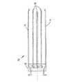
本発明を好ましい実施形態を用いて更に説明するが、それらは単に例示に過ぎず、本発明はそれらに限定されるものではない。従来の内視鏡を図1に示す。この内視鏡は、操作スイッチ、角状ロック(angulation lock)等の特性をいくつか有する。本発明のデバイスにもこれらのものが存在するが、従来のものであり、当業者にはよく知られているので以下の説明において詳細には説明しない。従って、以下の説明では、本発明を示すのに必要な要素のみを説明する。しかしながら、簡潔に説明すると、図1に図示され全体を10で示す内視鏡は、吸込バルブ、ロック、スイッチ等を備えた制御部11とを備える。例示のため、スイッチを2〜5で示す。また、空気や水の取込口、光ガイド等と接続するのに用いられる接続部6を有する。例示のため、光ガイドを7で示す。挿入管8は、三個の別の部分、即ち、可撓部9、関節部12、遠位端13からなる。関節部を更に詳細に図2に示す。図2には遠位端チップ24も示され、その中に遠位端13が存在する。 The invention will be further described using preferred embodiments, which are merely exemplary and the invention is not limited thereto. A conventional endoscope is shown in FIG. This endoscope has some characteristics such as an operation switch and an angular lock. Although these exist in the device of the present invention, they are conventional and well known to those skilled in the art, and will not be described in detail in the following description. Accordingly, in the following description, only the elements necessary to illustrate the invention are described. Briefly, however, the endoscope shown in FIG. 1 and generally indicated by 10 includes a
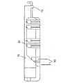
ここで図2を見ると、本発明の好ましい実施形態に係るステープラを具現化した内視鏡の遠位端部が概略的に示されている。この部分は、21で示されるステープル発射機構、関節部22、遠位端チップ24を含む。図1の関節部12は、関節部22、遠位端チップ24からなる。 Turning now to FIG. 2, a distal end of an endoscope embodying a stapler according to a preferred embodiment of the present invention is schematically shown. This portion includes a staple firing mechanism, indicated at 21, a joint 22, and a
次に、本発明に係るステープラと共に動作可能な内視鏡を更に詳細に説明する。 Next, an endoscope operable with the stapler according to the present invention will be described in more detail.
関節部22は従来の内視鏡のものと設計上は同様であるが、この実施例ではいくつかの特徴を有する。位置合わせ手順を簡略化すると共に精度を最大にするために、二方向関節運動の設計を採用した。これは関節部は一方向にのみ曲がるようになっている(即ち、内視鏡の遠位端チップは相対的に固定された面内において直線状態から一方の側のみに曲がると共に戻ることができる)ことを意味する。次に、このデバイスは、所望の医療処置を実施するために、従来の内視鏡より大きい270°まで曲げることができる。最後に、この関節部は、胃底部の拡張(外科的手続の例を参照して後述する)やクランプ、ステープルの際に組織に対して大きな力を提供するのに十分強固なものである。勿論、本発明のステープラは、各種内視鏡デバイスと共に使用することができ、特定の内視鏡と共に使用されることに制限されない。 The joint 22 is similar in design to that of a conventional endoscope, but this embodiment has several features. In order to simplify the alignment procedure and maximize accuracy, a bi-directional articulation design was adopted. This allows the joint to bend only in one direction (i.e., the distal tip of the endoscope can bend and return from a straight line to only one side in a relatively fixed plane. ) Means. The device can then be bent to 270 ° larger than a conventional endoscope to perform the desired medical procedure. Finally, the joint is strong enough to provide great force against the tissue during dilatation of the fundus (described below with reference to surgical procedures), clamping, and stapling. . Of course, the stapler of the present invention can be used with various endoscope devices and is not limited to use with a specific endoscope.
内視鏡の関節部の主な特徴を図19(a)と図19(b)に示す。関節部の典型的なリンクの全体を図19(a)において101で示す。各リンクは、一端においてリンクの外面と面一の外面を有する一対の円形ラグ102と、第二の端部においてラグ102の厚さ分凹陥した第二の対のラグ103とを有する。前記ラグの各々には孔104が貫通している。関節運動に必要なケーブルのために、四個の孔105がリンクの壁に開けられている。各リンクの中心を貫通する中空領域106が、光学チャンネル、照明チャンネル、吸引チャンネル等のチャンネルの内視鏡の遠位端チップへの挿通を可能にしている。 The main features of the joint portion of the endoscope are shown in FIGS. 19 (a) and 19 (b). An entire typical link of the joint portion is indicated by 101 in FIG. Each link has a pair of
図19(b)に図19(a)のリンク二個の間の接続を示す。第一のリンクの一対のラグ102は、第二のリンクの凹陥ラグ103に嵌合されている。旋回ピン107が両ラグの孔104に挿入されている。保持クリップ108の付加によりこの組立体が完成する。デバイスの別の特に好ましい実施形態では、保持クリップ108は設けられない。 FIG. 19B shows the connection between the two links in FIG. The pair of
リンクの長さ、リンク間の間隙(最大曲げ角度)、関節部全体の湾曲の半径や最大角度等の設計パラメータにより、関節部を形成するために結合するリンクの数が決まる。最初のリンク及び最後のリンクの外端はそれぞれ、内視鏡の残りの部分およびその遠位端チップと接続できるように設計される。 Design parameters such as the length of the link, the gap between the links (maximum bending angle), the radius of curvature of the entire joint and the maximum angle determine the number of links to be joined to form the joint. The outer ends of the first link and the last link are each designed to connect with the rest of the endoscope and its distal end tip.
旋回ピンはケーブル挿通用のクロスホール(cross-hole)を含む。クロスホールとケーブルは図19(a)と19(b)には図示していない。 The pivot pin includes a cross-hole for cable insertion. Cross holes and cables are not shown in FIGS. 19 (a) and 19 (b).
好ましい内視鏡においては、関節部は、一対のケーブル(あるいは、内視鏡の近位端に配置されるホイールに巻かれた一本のケーブル)を用いて関節を動かす。一方のケーブルは、曲げ円弧(bending arc)の内側のリンク壁内の孔を挿通し、内視鏡を曲げて曲げ位置にする。第二のケーブルは第一のケーブルの反対に配置され、この部分の曲げを戻す。作動機構は当業者にはよく知られており、ここで説明する必要はない。 In a preferred endoscope, the joint moves the joint using a pair of cables (or a single cable wound on a wheel located at the proximal end of the endoscope). One cable is inserted through a hole in the link wall inside the bending arc to bend the endoscope into the bending position. The second cable is placed opposite the first cable and returns the bend of this part. Actuating mechanisms are well known to those skilled in the art and need not be described here.
本発明の別の実施形態においては、ステープラを四方向関節運動システムと共に用いる。四方向システムでは、内視鏡のチップを互いに直角の二面内で動かすことができる。これにより、運動の自由度は増すが、位置合せ手続は複雑になり、後述する位置合せシステムの一個を使用する必要がある。四方向システムは、当分野においてよく知られているので、簡略化のためここでは説明しない。 In another embodiment of the invention, a stapler is used with a four-way articulation system. In a four-way system, the endoscope tip can be moved in two planes perpendicular to each other. This increases the freedom of movement but complicates the alignment procedure and requires the use of one of the alignment systems described below. Four-way systems are well known in the art and will not be described here for brevity.
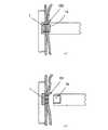
本発明の好ましい実施形態によれば、ステープラカートリッジは関節部22の近位端に置かれる。ステープラ展開システムは側面発射設計のものであり、遠位端チップの端部に配置されたアンビルを必要とする。ステープラカートリッジとアンビルモジュールは交換可能であり、シャフトと遠位端チップに設けた受け部に嵌装される。図2では、これらの受け部をそれぞれ1と1Aで表す。1と1Aのステープル要素がステープル組立体全体を構成する。次に、ステープル組立体についてより詳細に説明する。 According to a preferred embodiment of the present invention, the stapler cartridge is placed at the proximal end of the joint 22. The stapler deployment system is of a side firing design and requires an anvil placed at the end of the distal tip. The stapler cartridge and the anvil module are interchangeable and are fitted into receiving portions provided on the shaft and the distal end tip. In FIG. 2, these receiving parts are represented by 1 and 1A, respectively. 1 and 1A staple elements comprise the entire staple assembly. Next, the staple assembly will be described in more detail.
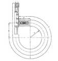
図3に、図2のデバイスが完全に関節運動した状態の概略を示す。関節部22は、固定曲率半径「r」で湾曲角度α曲げられている。半径「r」と関節部の長さの値は、固定値「l」(剛性遠位端チップの長さ)及び「y」(ステープリングが実施される位置から内視鏡の関節部分の近位端までの距離)を用いて、デバイスを完全に関節運動させたときにステープラ組立体の二部分が正確に位置合せされるように決められる。 FIG. 3 shows a schematic of the device of FIG. 2 fully articulated. The
図4は、図3と同様の図で、本発明の異なる実施形態のためのものであり、寸法の例を示したものであるが、本発明はこの寸法に限定されるものではない。図2、3、4は全て、第一の発射位置にあるステープラカートリッジを示す。 FIG. 4 is a view similar to FIG. 3 for a different embodiment of the present invention, showing an example of dimensions, but the present invention is not limited to this dimension. 2, 3 and 4 all show the stapler cartridge in the first firing position.
図5(a)は、内視鏡の遠位端チップ(図2における部分24)の概略を示す。ステープラ組立体の使い捨て可能なアンビルモジュールは、概略を32で示す受け部に嵌装される。二個の円形の再利用可能なプランジャー及びシールはアンビルホルダの一部であり、31で示される。吸引、洗浄、その他の目的用のチャンネルを35で示す。画像チャンネルを34、照明ファイバを33で示す。 FIG. 5A schematically shows the distal end tip (
他のオプションを設けることができ、実施される内視鏡手続の条件によって他の構成も可能であることは、当業者であれば分かるであろう。一例として、位置33の一箇所に変換器、受信器又は反射器を置き、これを後述のように超音波による位置決めに使用することができる。 One skilled in the art will appreciate that other options can be provided and other configurations are possible depending on the conditions of the endoscopic procedure being performed. As an example, a transducer, receiver or reflector can be placed at one
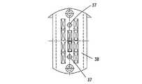
図5(b)は、アンビルユニット36が所定の位置に設けられた図5(a)の遠位端チップを示す。符号33、34、35は、図5(a)に示した部分と同じものを示す。符号37は、位置合せ/ロックピンがアンビルユニットから出る際に通る穴を示す。38は、ステープルを曲げるための、アンビルユニットの前面に設けられた凹部を示す。 FIG. 5 (b) shows the distal end tip of FIG. 5 (a) with the
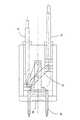
図6及び図7は、アンビルユニットの動作についての説明に必要な、使い捨て可能なアンビルユニットの内部を示す断面である。二種類の異なるシステムがこれらの図に図示されている。 6 and 7 are cross sections showing the inside of the disposable anvil unit, which is necessary for explaining the operation of the anvil unit. Two different systems are illustrated in these figures.
図6では、アクチュエータ機構43を用いて、保持/位置決めピンを進退させる。図7は、別の好ましいシステムを示す。サポートハウジングの内部には、二個のラック44と一個のピニオン45のシステムが設けられ、二本の保持/位置決めピン41の所望の運動を提供する。符号38は、ステープルの曲げを生じさせるアンビルの前面の凹部を示す。本発明の好ましい実施形態において用いる五個のステープルのパターンを示すアンビル前面を図8に示す。この図において、38はステープルの脚を曲げるための凹部を示し、37は保持/位置決めピンが突出する際に通る孔である。図6において、符号31はプランジャを示す。プランジャは、アンビルホルダの一部であって使い捨て可能なアンビルユニットの一部ではない。 In FIG. 6, the holding / positioning pin is advanced and retracted using the
ステープラの第二の部分は、使い捨て可能なステープラカートリッジを有するステープルカートリッジホルダからなる。ステープラカートリッジホルダは、内視鏡シャフトの固定部分、本発明の好ましい実施形態においては、関節部に近い固定部分に配置されている。図9(a)、図9(b)はそれぞれ、図2において1で示す箇所に配置されるこれらの部分の概略を示す側面図と正面図である。ステープルカートリッジホルダ51は、適切な内径と外径を有し側部に切欠き部を有するチューブからなる。その中で、切欠き部には、一枚の成形シートメタル(図示せず)が嵌められている。シートメタルは密閉シールを形成すると共に、適切な位置に使い捨て可能なステープルカートリッジ53を保持する。ステープルカートリッジを次の発射のために移動させるための正確な割出し位置が設けられている。 The second part of the stapler consists of a staple cartridge holder with a disposable stapler cartridge. The stapler cartridge holder is disposed at a fixed portion of the endoscope shaft, in the preferred embodiment of the present invention, at a fixed portion close to the joint portion. FIG. 9A and FIG. 9B are a side view and a front view, respectively, showing an outline of these portions arranged at a position indicated by 1 in FIG. The
チューブとシートメタルから成るサブアッセンブリに、プランジャガイドが取り付けられている。プランジャガイドには、プランジャと嵌合するシール(全体を符号52で示す)が設けられている。プランジャは、近位側方向に引かれたときにステープルアレイを発射し、その後の遠位側方向への押し動作によりステープルカートリッジを次の位置へ割出す。 A plunger guide is attached to a subassembly made of a tube and sheet metal. The plunger guide is provided with a seal (indicated by reference numeral 52) that fits with the plunger. When the plunger is pulled in the proximal direction, it fires the staple array and then pushes in the distal direction to index the staple cartridge to the next position.
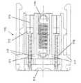
使い捨て可能なカートリッジケースは、二個のサブアッセンブリ、即ち、図10と図11に図示されるカートリッジ本体と、図13に図示される作動カムサブアッセンブリとを含む。 The disposable cartridge case includes two subassemblies, namely the cartridge body illustrated in FIGS. 10 and 11 and the actuation cam subassembly illustrated in FIG.
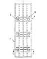
図10を参照する。ステープルカートリッジは、ステンレスあるいは他の適切な材料(適切なプラスチック等)で作られておりカートリッジ本体(全体を61で示す)を有している。本発明(the experiment)の好ましい実施形態においては、カートリッジ本体は、各々が五個のステープル63とそれらに対応するプッシャ(図11、14に示す)とから構成される三個のアレイを適切な距離で保持する。各ステープルアレイには、ラッチとばねを設けた二個の孔64が存在し、ばねはラッチを所望の方向に付勢して、アンビルから突出した位置決め/保持ピンに係止させる。カートリッジを割出すのに必要な三個の窓62が、カートリッジ本体の両側面に存在する。 Please refer to FIG. The staple cartridge is made of stainless steel or other suitable material (such as a suitable plastic) and has a cartridge body (generally indicated at 61). In a preferred embodiment of the experiment, the cartridge body suitably comprises three arrays, each consisting of five
図11は、図10のカートリッジ本体のA−A断面図であり、このサブシステムの主要な要素の概略を示す。この図において、符号64は図10に示した孔を示す。この図は各孔に向かって傾斜した入口を概略的に示す。この傾斜した入口によりピンが孔に入り易くなり、ピンが孔に入るとステープラの二部分が正確に位置合せされる。アレイのうちの中央のステープルを63で示し、そのプッシャを符号66で示す。符号65は爪を示し、符号68は板ばねを示す。これらの機能は、ステープルの発射の間、位置決め/保持ピンを所定の位置にロックすることである。図11では、符号69はラッチ爪の軸を示し、カムのためのプッシャ内の切欠きを67で示す。 FIG. 11 is a cross-sectional view of the cartridge main body of FIG. In this figure,
カートリッジはシートメタルハウジングを有する。該ハウジングは、カートリッジ自体を三辺で囲み、カートリッジを保持し、全ての作動カムを所定の位置に保持する。ハウジングの側面図を図18(a)に、上面図を図18(b)に示す。ハウジングは、二個の傾斜部分(angled portion)91を有する。該部分はカートリッジハウジングの一組の窓に係入し、カムがステープルアレイを発射する間、カートリッジが近位側に動くのを防ぐ。更に該部分は、遠位側に割出すときに次の位置への正確な位置決めのために使用される。 The cartridge has a sheet metal housing. The housing surrounds the cartridge itself on three sides, holds the cartridge, and holds all the operating cams in place. A side view of the housing is shown in FIG. 18 (a), and a top view is shown in FIG. 18 (b). The housing has two
作動カムサブアッセンブリ(図13の上面図において全体を72で示す)は、三個のアンギュラカム70から構成される。アンギュラカムは、図14のステープラ63を発射するステープルプッシャ66を作動させる。図14は、これらの要素間の関係を示す側面図である。三個のカム70は、クロス部材73に溶接される、あるいは他の方法で保持される。また、これらのカムの外側の二個の尾部は、次の位置への割出しのためにカートリッジ内に入り込むようにわずかに成形されている。 The working cam subassembly (generally indicated by 72 in the top view of FIG. 13) is composed of three
図13において二個の別の要素71が更に外側に存在する。これらの要素は、ステープルアレイの発射後にロック爪を開放し、位置合せ/保持ピンを開放するデバイスである。これらは、空間的制約のため、また、初期移動の前にドウェルが必要とされるため、カム組立体に溶接されていない。これらは、カム組立体の一部であるクロス部材73により作動される。 In FIG. 13, two
本発明の好ましい実施形態の上述の説明には、割出しのための三対の窓と、各々が五個のステープルを有する三個のアレイを発射するための三個のカムとを有するステープルカートリッジを説明したが、実施される手続の条件に応じ、アレイの数が異なり、アレイ一個あたりのステープルの数が異なる等の他の実施形態も提供され得ることは明らかである。 The above description of the preferred embodiment of the present invention includes a staple cartridge having three pairs of windows for indexing and three cams for firing three arrays each having five staples. However, it will be appreciated that other embodiments may be provided, such as different numbers of arrays and different numbers of staples per array, depending on the conditions of the procedure being performed.
図4と図12は、本発明の別の好ましい実施形態を示す。この実施形態においては、ステープラカートリッジは、各々が五個のステープルとこれらに対応するプッシャとから成る二個のアレイを含む。二個の窓がカートリッジ本体の各側面に存在し、カートリッジの割出しを補助する。カートリッジの残りの部分は全て、三個のアレイを含む実施形態のために上述したものと同様である。また、ステープラ展開システムとアンビルの位置は交換され得るものであること及びステープラの両要素は内視鏡の長軸に沿った様々な位置に配置され得ることは、当業者であれば理解できるはずである。例えば、ステープラシステムの部分の一方は、内視鏡の可撓性シャフト内の関節部と可撓部の間の接続部より近位側に配置され得る。また、例えば、ステープルアレイ一個のみが発射されるものである場合には、ステープルカートリッジを関節部のリンクのうちの一個に設けることによりデバイスの曲率半径を小さくすることも可能である。 4 and 12 illustrate another preferred embodiment of the present invention. In this embodiment, the stapler cartridge includes two arrays, each consisting of five staples and their corresponding pushers. Two windows are present on each side of the cartridge body to assist in indexing the cartridge. All the remaining parts of the cartridge are similar to those described above for the embodiment including three arrays. It should also be understood by those skilled in the art that the position of the stapler deployment system and the anvil can be interchanged and that both elements of the stapler can be placed at various positions along the long axis of the endoscope. It is. For example, one of the portions of the stapler system can be located proximal to the connection between the joint and the flexible portion in the flexible shaft of the endoscope. For example, when only one staple array is fired, the radius of curvature of the device can be reduced by providing the staple cartridge in one of the links of the joint portion.
ステープラシステムを機能させる方法の詳細の説明を、本発明のデバイスを用いて実施され得る典型的な外科手術、即ちGERD治療のために設計された胃底ヒダ形成手術の概略の説明を用いて次に述べる。 A detailed description of how to operate the stapler system follows with a general description of a typical surgical procedure that can be performed using the device of the present invention, ie, fundus fold surgery designed for GERD treatment. In the following.
図2に示すように、患者の内部に挿入したデバイスの位置の情報を提供するために位置決めマーク23を患者の外側にあるデバイス端部に設けてもよい。 As shown in FIG. 2, positioning marks 23 may be provided on the device end outside the patient to provide information on the position of the device inserted inside the patient.
また、内視鏡的視覚手段も設けることができる。図5(a)と5(b)は、内視鏡デバイスの遠位端チップの概略を示す。領域33は照明チャンネル、34は画像チャンネル、35は洗浄/吸引/超音波チャンネルである。画像化手段を遠位端チップに置くことにより、体腔内における所望の位置にデバイスを導くことを助け、外科的手続が行われている領域の画像化が可能となる。第二の光学画像も提供され得る。この画像は、ステープラの透明部を透過するビューであり、組織を貫通し曲げられて閉じられるときのステープルを示す。従来の内視鏡装置の光学システムを採用することができる。内視鏡は、二以上の個別ビューを作出する二以上の分離した光学チャンネルを含んでもよい。好ましい内視鏡光学システムは、本出願と同一の出願人による係属中の国際特許出願PCT/IL01/00238(2001年3月12日出願)の明細書に記載されており、この明細書を本発明の一部を構成するものとしてここに援用する。しかしながら、採用されている特定の光学システムは本発明と関係なく、当業者であれば多くの様々な光学システムを提供して、本発明の装置と共に使用することができる。 Endoscopic visual means can also be provided. 5 (a) and 5 (b) show a schematic of the distal end tip of the endoscopic device.
上述の本発明の好ましい実施形態においては、ステープラの二個の分離した部分の位置合せは、厳密に言って機械的手段により達成される。該手段は、固定曲率半径と内視鏡のステープラ及び関節部の正確な設計及び製造とにより実現できる。しかしながら、本発明の別の実施形態では、位置合せ組立体を設けることが必要になる場合もある。この位置合せ組立体は二個の要素から構成される。これらの要素はステープラの両部分の近くに一個ずつ配置され、これらの要素が位置合せされると、ステープラ組立体の両部分の位置が合うことを確実にし、よってステープラの作動を可能にする。本発明の好ましい実施形態によれば、位置決め組立体の要素は、超音波要素、即ち、超音波変換器と受信器、あるいは変換器と反射器である。受信器で受信した超音波信号の分析は簡単で当業者にはよく知られているが、この分析により、正確な位置の一致に相当する最大の信号を決定するか、あるいは変換器と受信器や反射器との間の距離を測ることができる。 In the preferred embodiment of the invention described above, the alignment of the two separate parts of the stapler is achieved strictly by mechanical means. The means can be realized by a fixed radius of curvature and precise design and manufacture of the endoscope stapler and joints. However, in other embodiments of the present invention, it may be necessary to provide an alignment assembly. This alignment assembly consists of two elements. These elements are placed one by one near both parts of the stapler, and when these elements are aligned, they ensure that both parts of the stapler assembly are aligned, thus allowing operation of the stapler. According to a preferred embodiment of the invention, the elements of the positioning assembly are ultrasonic elements, i.e. ultrasonic transducers and receivers, or transducers and reflectors. The analysis of the ultrasound signal received at the receiver is simple and well known to those skilled in the art, but this analysis determines the maximum signal corresponding to an exact position match, or the transducer and receiver. And the distance between the reflector and the reflector.
本発明の別の好ましい実施形態によれば、位置決め組立体の要素の一方は光を発し、他方は受けた光を信号に変換する感光要素である。この場合も、信号の最大強度は、位置合せが最適であることを示す。 According to another preferred embodiment of the invention, one of the elements of the positioning assembly emits light and the other is a photosensitive element that converts the received light into a signal. Again, the maximum strength of the signal indicates that the alignment is optimal.
本発明の更に別の実施形態によれば、位置決め組立体の要素の一方は圧電変換器であり、他方は単なる突起である。突起により薄い組織を介して圧電変換器に圧力が加えられると、電気信号が発生する。この場合も、この電気信号を分析して最大値を決定することができる。 According to yet another embodiment of the invention, one of the elements of the positioning assembly is a piezoelectric transducer and the other is just a protrusion. An electrical signal is generated when pressure is applied to the piezoelectric transducer through the thin tissue by the protrusion. Again, this electrical signal can be analyzed to determine the maximum value.
当業者であれば分かるように、多くの他の方法やシステムを、システムが正しく位置合せされているか否かを確認するために考え出すことができる。例えば、RF信号を用いて正しく位置合せされたことを決定する、即ち磁場発生器を一方の部分に、磁場位置センサを他方の部分に用いることができる。ここで留意すべきことは、或るタイプの位置決め組立体においては、例えば、RF組立体を用いることが望まれる場合には、組立体の二個の要素が物理的に位置合せされる、即ちこれらの物理的な中心が本質的に位置合せされることは全く必要ではない。位置合せ手続が物理的な中心同士の一致によるものでなければ、それらが最適な位置合せを示す出力信号を発したときにステープル組立体の要素1と1A(図2)が実際に物理的に位置合せされるものである限り、二個の要素はデバイスの二部分の異なる位置に置くことができる。 As those skilled in the art will appreciate, many other methods and systems can be devised to ascertain whether the system is properly aligned. For example, RF signals can be used to determine correct alignment, i.e., a magnetic field generator in one part and a magnetic field position sensor in the other part. It should be noted here that in certain types of positioning assemblies, for example if it is desired to use an RF assembly, the two elements of the assembly are physically aligned, i.e. It is not absolutely necessary for these physical centers to be essentially aligned. If the alignment procedure is not due to physical center-to-center alignment, the
内視鏡装置は、口、肛門、膣等の元々存在する開口部に挿通することができ、これにより例えば結腸ポリープや小さい癌の切除、胃病巣部の全厚バイオプシー、胃食道逆流症の治療等の手続を実施するにあたり全身麻酔の使用の必要性を回避することができる。 Endoscopic devices can be inserted through the originally existing openings such as mouth, anus, vagina, etc., for example, removing colon polyps and small cancers, full thickness biopsy of gastric lesions, treatment of gastroesophageal reflux disease It is possible to avoid the necessity of using general anesthesia in carrying out such procedures.
本発明の装置の使用を説明するために、胃食道逆流症(GERD)の治療のための内視鏡による胃底ヒダ形成を実施する医療手続を例として選んたが、本発明はこれによって限定されるものではない。GERDの症状及び治療については当分野において広範囲に説明されているとともに前記国際特許出願においても説明されているので、簡略化のためここでは詳細には説明しない。 To illustrate the use of the device of the present invention, a medical procedure for performing endoscopic fundus fold formation for the treatment of gastroesophageal reflux disease (GERD) was taken as an example, but the present invention is limited thereby. Is not to be done. Since the symptoms and treatment of GERD have been extensively described in the art and also in the international patent application, they will not be described in detail here for the sake of brevity.
本発明のデバイスは、三個の別の操作段階、即ち、1)導入手続(機械的操作の前に、所望の位置にデバイスを置く)、2)デバイスの機械的操作(胃底部を伸長し、外科的操作の前にステープラの両部分を正確に位置合せする)、3)外科的操作(生体(living)組織をステープルで固定する)を有する。次にこれらの操作について詳細に説明する。 The device of the present invention has three separate operating stages: 1) introduction procedure (place the device in the desired position before mechanical operation), 2) mechanical operation of the device (extending the stomach floor) And accurately align both parts of the stapler prior to the surgical operation) and 3) surgical operation (stabilizing the living tissue with staples). Next, these operations will be described in detail.
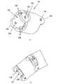
導入手続
内視鏡デバイスを患者の胃に導入する手続を図2、図3、図24を参照しながら説明する。内視鏡デバイスをバイタ(biter)を介して患者の食道へ導入する。バイタ(図24に断面図を示す。全体を110で示す。)は噛む部分111を有し、該部分は患者の歯の間に保持される。内視鏡デバイス(図示せず)は、バイタの適切な開口112を介して導入される。動作位置においては、ステープラモジュール(図2において1で示す)は胃食道接合部(GJ)から一定の距離(通常、約5〜6cmの範囲)に配置されなければならない。GJは、最初にデバイスを導入するときに内視鏡の観察手段を用いた視覚による検査で確認される。この段階における導入されたデバイスの全長は、図2を参照して説明した位置決めマーク23に示される値を読むことにより測定される。内視鏡を更に胃の中に前進させる。この時点では、内視鏡はGJの上方に所望の距離だけ離れた位置に配置される。ここで、内視鏡を通常のクランプ手段(図示せず)を用いてバイタに固定することにより、内視鏡を所望の位置にロックする。Introduction Procedure A procedure for introducing the endoscope device into the stomach of a patient will be described with reference to FIGS. An endoscopic device is introduced into the patient's esophagus via a biter. The vita (shown in cross section in FIG. 24, generally designated 110) has a chewing
デバイスの機械的操作
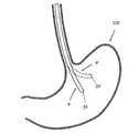
このデバイスの機械的操作では、胃底部と遠位端チップを係合させそれを食道下部に向けて動かすようにデバイスの曲げ可能な部分の関節運動を行う。この概略を図20、21、22に示す。図20においてデバイスの二種の位置をaとa’で示す。位置aは、デバイスを患者の口と食道を通して所望の位置に挿入した後の初期の位置である。位置a’は、デバイスの関節部22(図2)の胃底部120に向かっての曲げ動作の開始を示す。チップを24’で示す。Mechanical operation of the device The mechanical operation of the device involves articulating the bendable portion of the device to engage the gastric floor and distal tip and move it toward the lower esophagus. This outline is shown in FIGS. In FIG. 20, two positions of the device are indicated by a and a ′. Position a is the initial position after the device is inserted through the patient's mouth and esophagus to the desired position. Position a ′ indicates the beginning of a bending motion toward the
図21では、デバイスの関節運動は、遠位端チップ24が胃底部120の壁に接し食道の下部に向けて押し上げ始めた段階に進んでいる。 In FIG. 21, the articulation of the device has progressed to the stage where the
図22では、デバイスの関節運動は略完了し、遠位端チップ24により胃底部120が初期の位置から食道下部付近の位置まで動かされた状況を示している。この位置において、チップ24により胃底部は正しい位置に置かれており、胃底部と食道をステープル接合することができる。 In FIG. 22, the articulation of the device is substantially complete, and the
図23は、内視鏡の関節運動が完了したときの状況のより詳細な図である。ここには、食道130内の内視鏡の関節部の近位側に設けられたステープルカートリッジ1と、胃底部120内の遠位端部24に設けられたアンビル1Aとの間の位置合せの概略を示す。 FIG. 23 is a more detailed view of the situation when the endoscope articulation is complete. Here, the alignment between the
外科的操作
ここで、組織のステープル固定を参照して外科的操作を説明する。ステープル組立体を用いて図23における胃底部の下部120を食道の下部130に固定するためには、ステープルが発射されたときにアンビルの凹部に正確に入り所望の仕事が達成されるように、要素1と要素1Aを正しい動作位置関係に置くことが肝要である。ステープル組立体の各部分を正しい位置関係に置けない場合、組織の保持のためにステープルが正しく成形されず、更にはステープル固定が実施された箇所の組織を損傷する危険が高くなるので患者を害する可能性がある。更には、胃底部が食道にステープル固定されないため、この手続の目的が達成されない。Surgical Operation The surgical operation will now be described with reference to tissue stapling. In order to secure the fundus
上述のように、二方向内視鏡を用いる本発明の好ましい実施形態においては、デバイスの設計により、固定の曲げ半径でデバイスを関節運動させることにより、適切な位置合せを確実に行うことができる。必要であれば、本明細書に記載の超音波や他の技法を用いて位置合せを補助する。 As described above, in a preferred embodiment of the present invention using a two-way endoscope, the device design allows for proper alignment by articulating the device with a fixed bend radius. . If necessary, the ultrasound and other techniques described herein are used to assist in alignment.
四方向内視鏡を用いる本発明の他の好ましい実施形態においては、ステープラの二部分の位置合せを行うためにこれらの手段のうちの一個を用いなければならない。外科医は、内視鏡の遠位端チップに設けた視覚化手段を用いて、位置決め、胃底部の食道へ向けての適切な伸長、及びステープル固定の結果を確認することができる。内視鏡が上述の本発明の好ましい実施形態に係る光学システムを備えている場合、第二の独立した光路が設けられる。これにより、外科医は、ステープル発射が行われる前及び後にステープル発射部分側からその部位を観察することができる。更に、ステープラの二部分が相互に押圧されるので、それらの間の組織が圧縮されて組織を透過して見ることが可能となり、デバイスの適切な位置決めや位置合せを視覚的に確認できる。 In another preferred embodiment of the invention using a four-way endoscope, one of these means must be used to align the two parts of the stapler. The surgeon can use the visualization means provided on the distal tip of the endoscope to confirm the results of positioning, proper extension of the fundus toward the esophagus, and staple fixation. If the endoscope is equipped with an optical system according to a preferred embodiment of the invention described above, a second independent optical path is provided. Accordingly, the surgeon can observe the portion from the side of the staple firing portion before and after the staple firing is performed. Further, since the two portions of the stapler are pressed against each other, the tissue between them can be compressed and viewed through the tissue, and the proper positioning and alignment of the device can be visually confirmed.
最終的な位置合せは、ステープラのアンビル部に設けたロックピンを展開することにより達成される。位置決め/ラッチピンの展開を達成するための本発明の好ましい実施形態における方法は、図6、7、11を参照することにより理解できる。一本の遠位側ケーブルを作動させ、一方のプランジャ31を前に動かす。続いてプランジャは、ラックギヤ44とピニオンギヤ45によりピン41を前方に動かす。ピンは胃底部と食道の壁の組織を貫通し、傾斜入口によってステープルカートリッジに設けられた孔(図11で64で示す)に導かれる。これにより、ステープラの二部分の最終的な位置合せを確実に行うことができる。 Final alignment is achieved by deploying a lock pin provided on the anvil portion of the stapler. The method in the preferred embodiment of the present invention for achieving positioning / latch pin deployment can be understood with reference to FIGS. One distal cable is activated and one
アンビル部内のプランジャやステープルカートリッジホルダ内の発射プランジャを作動させるのに用いる技法は、当業者にはよく知られているので、簡略化のためここでは説明しない。ピンがステープラホルダ内の孔に前進して入ると、ピンは爪(図11で65で示す)により係合、ロックされる。ピンを前進させるケーブルをここで緩め、次に他方のケーブルを作動させて爪によるロックを確認し、組織をクランプし、所望の組織間の間隙を設ける。 The techniques used to actuate the plunger in the anvil and the firing plunger in the staple cartridge holder are well known to those skilled in the art and will not be described here for the sake of brevity. When the pin advances and enters the hole in the stapler holder, the pin is engaged and locked by a claw (indicated by 65 in FIG. 11). The cable that advances the pin is now loosened, and then the other cable is actuated to confirm locking by the nail, clamp the tissue, and provide the desired inter-tissue gap.
超音波技法を用いたステープルカートリッジとアンビル間の距離の測定を、爪によるロックピンのロックを確認するのに用いることができる。本発明の別の実施形態では、電子的安全機構が提供されて、位置決め/ロックピンがステープラカートリッジ内の爪によりロックされない場合にステープルの発射を阻止する。上述の国際特許出願には、ステープル操作の状態を示すディスプレイシステムが記載されている。この視覚情報を提供するのに用いられるセンサも、ステープルの偶発的放出を防止するのに用いることができる。 Measurement of the distance between the staple cartridge and the anvil using ultrasonic techniques can be used to confirm locking of the lock pin by the nail. In another embodiment of the present invention, an electronic safety mechanism is provided to prevent firing of staples when the positioning / locking pin is not locked by the pawl in the stapler cartridge. The above-mentioned international patent application describes a display system that indicates the status of stapling operation. Sensors used to provide this visual information can also be used to prevent accidental release of staples.
図26(a)に外科的操作の段階の状況を示す。複数のロックピン(全体を150で表す)は、アンビル組立体1Aに収容されており、胃底部と食道の壁の組織を貫通して伸長され、ステープラカートリッジ1のソケットにロックされる。ロックピンは、適切な位置合せを確実にするだけでなく、ステープリングの際の所望の組織間間隙を維持するものでもある。従来技術に係るステープラのアンビルとステープル容器/イジェクタ部分の間が剛性あるいは半剛性接続であるのに対し、本発明のステープラがその二部分間の接続が全体的に可撓性を有するものであっても機能できるのは、このロックピン(又は同様のあるいは同等のロック手段)があるためである。 FIG. 26A shows the state of the surgical operation stage. A plurality of locking pins (denoted as a whole by 150) are accommodated in the
ステープルアレイを発射するために、次に発射プランジャ(図9(a)と図9(b)において52で示す)に取り付けたケーブルを近位側に引く。これにより、クロス部材(図13〜17において73で示す)が該部材に取り付けられたカムと共に引き戻される。ステープルの発射方法は、図14〜17から理解できる。カム(70)が近位側に動くと、その傾斜した面がステープルプッシャ(66)の傾斜面と係合し、プッシャをカートリッジの壁方向に向かって横方向に動かし、ステープル(63)をカートリッジの側部から放出して食道と胃の壁の組織を貫通させる。ステープルの脚は、アンビルの前面の凹部に係合し曲がり始める。図14〜17は、一個のステープルアレイの発射の際の各段階を示す。全てのアレイのステープルが発射されると、開放カム(図13において71で示す)は爪の近位端に力を加え、ピンのラッチを開放する。クランプを作動させた遠位側のケーブルが引かれてピンをアンビルに戻し、この外科的操作のフェーズは完了する。 To fire the staple array, the cable attached to the firing plunger (shown at 52 in FIGS. 9 (a) and 9 (b)) is then pulled proximally. Thereby, the cross member (indicated by 73 in FIGS. 13 to 17) is pulled back together with the cam attached to the member. The method for firing staples can be understood from FIGS. As the cam (70) moves proximally, its inclined surface engages the inclined surface of the staple pusher (66), moving the pusher laterally toward the wall of the cartridge and moving the staple (63) into the cartridge. Releases from the sides of the esophagus and penetrates the tissue of the stomach wall. The staple legs engage the recesses on the front surface of the anvil and begin to bend. FIGS. 14-17 illustrate the stages during firing of a single staple array. When all arrays of staples have been fired, the release cam (designated 71 in FIG. 13) applies a force to the proximal end of the pawl, releasing the pin latch. The distal cable that actuated the clamp is pulled back to return the pin to the anvil, completing this phase of surgical operation.
図26(b)に、ステープル動作を行った後の状態を示す。複数のステープル(全体を151で表す)は、動作を実施した特定の場所において、胃底部と食道を結合している。 FIG. 26B shows a state after the stapling operation is performed. A plurality of staples (generally indicated at 151) connect the fundus and the esophagus at the specific location where the operation was performed.
位置合せ/ロックピンの動作により生じる組織内の小さな孔は、皮下注射により作出される孔と同様であり、自然にふさがる。孔は、その上方と下方のステープルによって保護され得る。好ましい実施形態では、三列のステープルとその中央の列に整列されたピンホールからなる構成(例えば図5(b)に図示した構成)がこの目的を達成するために選択される。 The small holes in the tissue caused by the movement of the alignment / lock pin are similar to the holes created by subcutaneous injection and are naturally plugged. The hole can be protected by staples above and below it. In a preferred embodiment, a configuration consisting of three rows of staples and pinholes aligned in its central row (eg, the configuration shown in FIG. 5 (b)) is selected to achieve this purpose.
図25(a)は発射前のステープルを示す。図25(b)は、脚がアンビル内で曲げられた後のステープルの形状を示す。 FIG. 25 (a) shows the staple before firing. FIG. 25 (b) shows the shape of the staple after the legs are bent in the anvil.
ステープルの検査後、外科医は次に必要に応じて関節部を開放し、胃の内部の組織のクランプを全て取り除く。次にデバイスを次の位置に回転させ、関節運動/位置合せ手続を繰り返す。 After examining the staples, the surgeon then opens the joints as necessary and removes all tissue clamps in the stomach. The device is then rotated to the next position and the articulation / alignment procedure is repeated.
三個の発射カムのうちの外側二個の尾部はばね力によって付勢されており、これによりカムは一方向のみに動くようになっている。次に発射プランジャが遠位側に押されるが、カムはこの方向には動くことができないので、これにより第二のアレイがアンビルに対向する位置にカートリッジ全体を前方に割出す。カートリッジが遠位側に動くと、ハウジングの傾斜部分は、カートリッジ側部の最初の窓の組から滑りながら外れる。割出しは、前記部分が二番目の窓の組に嵌まったときに完了する。 The two outer tails of the three firing cams are biased by a spring force so that the cam moves only in one direction. The firing plunger is then pushed distally, but the cam cannot move in this direction, thereby indexing the entire cartridge forward to a position where the second array faces the anvil. As the cartridge moves distally, the sloped portion of the housing slides off the first set of windows on the cartridge side. Indexing is complete when the part fits into the second set of windows.
最終位置合せのプロセス、即ち、位置決め/ロックピンの展開及びロックと、二番目のステープルアレイの発射を繰り返す。三個のアレイを含む実施形態の場合、上述のプロセス全体を三回繰り返し、部分胃底ヒダ形成を完了する。アレイ及び/又は発射の数は医療的観念からの各種考慮によって異なる。即ち、実施される医療手続や患者の特性等の因子による。 The final alignment process is repeated: positioning / lock pin deployment and locking, and firing the second staple array. For embodiments including three arrays, the entire process described above is repeated three times to complete partial fundus fold formation. The number of arrays and / or firings depends on various considerations from a medical concept. That is, it depends on factors such as medical procedures to be performed and patient characteristics.
本発明の好ましい実施形態においては、位置合せ/ロックピン及び/又はロック爪は、安全上の対策から、ステンレス等の適切な材料で作製される。この材料は、これらの部品を通常操作において上述のように機能させるのには十分な強度を有するが、開放カムがピンのロックを外すことができなかったときには、関節部の曲げを戻すことにより付与される力によってピンの先端は破壊され得る。 In a preferred embodiment of the invention, the alignment / lock pin and / or lock pawl is made of a suitable material such as stainless steel for safety reasons. This material is strong enough to allow these parts to function as described above in normal operation, but if the release cam is unable to unlock the pin, it will return the joint to the bend. The tip of the pin can be destroyed by the applied force.
内視鏡の操作を数多く繰り返した後は、部品の磨耗、特に関節部における磨耗により、遠位端チップに設けられたアンビルが、内視鏡シャフト内のステープラカートリッジと適切に位置合せされることが困難になる可能性がある。この困難は、ステープル組立体の前記部分を各種手段を用いて内視鏡デバイスの軸に沿って移動させることにより克服することができる。本発明の好ましい実施形態によれば、これは、ステープル組立体の前記部分に配置される雌ねじに結合された可撓性ねじ付きケーブルの動作により達成される。本発明の好ましい一実施形態では、可撓性ねじ付きケーブルは内視鏡デバイス内に配置され、内視鏡デバイスの本体の壁に設けられたスリットを経由して雌ねじと接触している。本発明の別の好ましい実施形態では、可撓性ねじ付きケーブルは内視鏡デバイスの外壁に埋め込まれ、ステープル組立体の上記部分の雌ねじと直接接触している。 After many operations of the endoscope, the anvil provided on the distal tip is properly aligned with the stapler cartridge in the endoscope shaft due to wear of parts, particularly at the joint. Can be difficult. This difficulty can be overcome by moving the portion of the staple assembly along the axis of the endoscopic device using various means. According to a preferred embodiment of the present invention, this is achieved by the operation of a flexible threaded cable coupled to an internal thread disposed in the portion of the staple assembly. In a preferred embodiment of the present invention, the flexible threaded cable is disposed within the endoscopic device and is in contact with the internal thread via a slit provided in the wall of the body of the endoscopic device. In another preferred embodiment of the present invention, the flexible threaded cable is embedded in the outer wall of the endoscopic device and is in direct contact with the internal thread of the portion of the staple assembly.
本発明の好ましい一形式では、可撓性ねじ付きケーブルをマイクロメトリック組立体(micrometric assembly)を用いて回転させ、これにより食道内に位置するステープル組立体の前記部分を制御された一定の距離だけ移動させる。 In a preferred form of the invention, a flexible threaded cable is rotated using a micrometric assembly, thereby causing the portion of the staple assembly located within the esophagus to be controlled a fixed distance. Move.
本発明の別の好ましい実施形態においては、上述の実施形態の位置合せ/ロックピンをねじで置き換える。このために必要なアンビルユニットの変更点について、図27、28、29、30、31を参照して説明する。 In another preferred embodiment of the present invention, the alignment / lock pin of the above embodiment is replaced with a screw. Changes in the anvil unit necessary for this will be described with reference to FIGS. 27, 28, 29, 30 and 31.
図27は、内視鏡160の遠位部分の概略断面図であり、ステープラのアンビル部162とステープラカートリッジ161を示す。図示されているステープラカートリッジの部分は、発射カム165の一個、ステープル167、対応するステープルプッシャ166である。ねじ171は、ステープリングの実施を可能にするために、ねじ作用によってアンビルから出てカートリッジに入る。符号164は、プランジャ163に取り付けられた発射ケーブルを示す。プランジャは、ステープルカートリッジ内のカムに接続される。 FIG. 27 is a schematic cross-sectional view of the distal portion of the
図28は、アンビルユニットの交換可能な部分の主な要素を示す断面図であり、アンビルユニットの全体を符号170で示す。ねじ171は、方形の頭部172を有する。符号173はチューブを示し、その機能は一組のギアの回転運動をねじの頭部に伝達し、これによりねじを回転させて前進させアンビルから突出させることである。チューブ173は外側が円形で、内側が方形である。ねじの頭部が面176に当接すると、更なる回転により、アンビルを有する部分177が内視鏡の遠位端からカートリッジに向けて引き出される。符号174はアンビルの前面に設けられた凹部を示し、ステープルを曲げるものである。ばね175は、アンビルとカートリッジの接続を外した後にねじを後退させた際、アンビルを内視鏡の遠位端に引き戻す。 FIG. 28 is a cross-sectional view showing the main elements of the replaceable portion of the anvil unit, and the entire anvil unit is denoted by
図29は、図27と直行する面内における、アンビルユニットとカートリッジの概略断面図である。図29は、ステープラの動作の説明に必要なカートリッジ161とアンビル部162の主な特徴を示す。図29の上半分(X−Xより上)はねじを前進させる前の状況を示し、図の下半分(X−Xより下)はステープルが発射された後のステープラに接続したアンビルを示す。符号160は内視鏡を示し、183と184はステープリングされる二層の組織を示す。例えばGERD手術の場合、183は胃底部の組織であり、184は食道の組織である。 FIG. 29 is a schematic cross-sectional view of the anvil unit and the cartridge in a plane perpendicular to FIG. FIG. 29 shows the main features of the
アンビル部162は二個の部分からなる。即ち、交換可能なユニット170(図28を参照して説明)と、全体を180で示す内視鏡の遠位端チップに恒久的に設けられる部分である。部分180は三個のギア181を含み、その位置を図29の矢印で示す。図30にその詳細を示す。この図は遠位端チップの端面図であり、ステープルカートリッジの方向を見ている。中央のギアはねじ駆動ケーブル182に接続され、該ケーブルは内視鏡の長さ方向に延設されて近位端において回転される。このケーブルとこれを操作する手段は当分野においてよく知られており、ここで更なる説明はしない。二個の側部のギアはそれぞれチューブ173の一本に接続される。このようにしてねじ駆動ケーブルの回転によりギアが回転し、これによりねじを前進あるいは後退させる。 The
図31はアンビルユニットのA−A断面を示す。符号185はナットを示し、ねじ171がその中を貫通する。符号186はクラッチシステムを示す。図31に示したシステムは、最初はねじを案内し組織を貫通させステープルカートリッジの中に入れる。ナット185の外側は鋸歯状である。従って、回転が連続すると、ナットはクランプを可能にする。ねじを後退させるときはナットは回転できない。従って、積極的なねじの引き抜きが達成される。 FIG. 31 shows an AA cross section of the anvil unit.
カートリッジ161はいくつかのステープルアレイ167、ステープルプッシャ166、発射カム165を含み、その動作については上に説明した。各ステープルアレイは、アンビル部のねじが入る二個の孔182を伴う。孔の内部はねじが切られていてもよいが、本発明の好ましい実施形態においては、カートリッジはプラスチックで作られ、ねじ171はカートリッジ内に前進するに従い自身のねじ山を作り出すタッピングねじである。位置合せ/ロックピンを用いる本発明の実施形態に記載されたカートリッジをこの実施形態にも採用することができる。しかしながら、図11に示す爪とばね、図13に示す二個の外側のカムは、ねじの場合は不要であり、これらの部分を含まないカートリッジはその製造が簡単であるため好ましい。 The
次に、本発明のこの実施形態を用いた場合の一連の操作を簡潔に説明する。内視鏡を患者に挿入し、次に関節部分を270°湾曲させる。上記の国際特許出願PCT/IL01/00238に記載した超音波技法を用いるかあるいは他の適切な技法により、カートリッジとアンビルの相対的な位置合せが行われたことが判定される。必要であれば位置合せを次のようにして調整できる。ステープル発射ケーブルを押してカートリッジを理論的位置整合点を若干過ぎたところまで割出し、その後超音波や他の手段により案内されて発射ケーブルを後退させて正確な位置合せを達成する。別法として、元の位置が位置整合点に達しない場合、ケーブルに対する従来の精密制御を用いてフリンジング(fringing)ケーブルを更に押し、最終アライメントを達成する。操作のこの段階の状況を図29の上半分(X−Xより上)に図示する。 Next, a series of operations when this embodiment of the present invention is used will be briefly described. An endoscope is inserted into the patient, and then the joint portion is bent 270 °. It is determined that the relative alignment of the cartridge and the anvil has been performed using the ultrasonic technique described in the above-mentioned international patent application PCT / IL01 / 00238, or other suitable technique. If necessary, the alignment can be adjusted as follows. The staple firing cable is pushed to index the cartridge just past the theoretical registration point and then guided by ultrasound or other means to retract the firing cable to achieve accurate alignment. Alternatively, if the original position does not reach the alignment point, conventional precision control over the cable is used to further push the fringing cable to achieve final alignment. The situation at this stage of operation is illustrated in the upper half of FIG. 29 (above XX).
次にねじ駆動ケーブルを回転させ、ギアを介してねじを前進させ組織を貫通させてカートリッジに入れる。更なる回転により、内視鏡の遠位端からアンビルを引き出し組織をクランプする。アンビルとカートリッジの間の距離を、例えばPCT/IL01/00238に記載の超音波システムを用いて、あるいは他の適切な手段により測定する。更なる調整が必要でなければ、ステープル発射ケーブルを引く。ステープル発射ケーブルを引くことによりカートリッジ内のカムを引き戻し、最初のステープルアレイを発射する。操作のこの段階の状況を図29の下半分(X−Xより下)に図示する。167’はカートリッジから放出され組織を貫通したステープルを示し、その脚はアンビルの前面に設けられた凹部に押圧されて曲げられている。 The screw drive cable is then rotated and the screw is advanced through the gear to penetrate the tissue and into the cartridge. Further rotation pulls the anvil from the distal end of the endoscope and clamps the tissue. The distance between the anvil and the cartridge is measured, for example using an ultrasound system as described in PCT / IL01 / 00238, or by other suitable means. If no further adjustment is needed, pull the staple firing cable. Pulling the staple firing cable pulls back the cam in the cartridge and fires the first staple array. The situation at this stage of operation is illustrated in the lower half of FIG. 29 (below XX). Reference numeral 167 'denotes a staple which is discharged from the cartridge and penetrates the tissue, and its leg is bent by being pressed by a recess provided on the front surface of the anvil.
次にねじ駆動ケーブルを反対方向に回転させる。これにより、ねじはカートリッジと組織から抜かれ、アンビルは内視鏡の遠位端の中に後退する。次に関節部を直線状に伸ばし、ステープルカートリッジを次の位置に割出し、必要であれば二番目のステープルアレイを展開できるように準備する。本発明の実施形態を図示により説明したが、当業者であれば、本発明の精神から逸脱することなく、また請求項の範囲を越えることなく、多くの変更、変形、適合化を行って本発明を実施できることが理解されよう。 The screw drive cable is then rotated in the opposite direction. This unscrews the cartridge and tissue and retracts the anvil into the distal end of the endoscope. Next, the joint portion is extended linearly, the staple cartridge is indexed to the next position, and if necessary, the second staple array is prepared for deployment. Although the embodiments of the present invention have been described with reference to the drawings, those skilled in the art may make many changes, modifications and adaptations without departing from the spirit of the present invention and without departing from the scope of the claims. It will be appreciated that the invention can be practiced.
160 内視鏡
161 ステープラカートリッジ
162 アンビル部
163 プランジャ
164 発射ケーブル
165 発射カム
166 ステープルプッシャ
167 ステープル
171 ねじ
Claims (40)
Translated fromJapanese前記ステープルデバイスは、ステープル発射部と、アンビル部と、前記ステープル発射部又は前記アンビル部に収容された一以上の位置合せ及び/又はロック部材と、前記ステープル発射部又は前記アンビル部の他方に設けられた受け部と、前記位置合せ及び/又はロック部材を伸長及び後退させる機構とを有し、
前記ステープル発射部と前記アンビル部は、前記内視鏡デバイスの長手方向軸に沿って長手方向に互いに離間して設けられ、その間に前記可撓部の少なくとも一部が設けられ、
前記ステープルデバイスの両部分が正しい動作関係になるようにするべく、前記可撓部は曲がるように適合し、且つ前記機構は一以上の前記位置合せ及び/又はロック部材を前記受け部に伸長されて係合してロックするために動作するように適合していることを特徴とする、ステープルデバイス。A stapling device for a surgical endoscopic device comprising at least one flexible part, comprising:
The staple device includes a staple firing unit, an anvil unit, one or more alignment and / or locking members housed in the staple firing unit or the anvil unit, and the other of the staple firing unit or the anvil unit. Anda mechanism for extending and retracting the alignment and / or locking member ,
The staple firing portion and the anvil portion are provided to be separated from each other in the longitudinal direction along the longitudinal axis of the endoscope device, and at least a part of the flexible portion is provided therebetween.
The flexible portion is adapted to bend and the mechanism is extended with one or more of the alignment and / or locking members to thereceiving portionso that both portions of the stapling device are in the correct operational relationship. Staple devicecharacterized in that it is adapted to operate to engage and lock.
Applications Claiming Priority (2)
| Application Number | Priority Date | Filing Date | Title |
|---|---|---|---|
| IL139788AIL139788A (en) | 2000-11-20 | 2000-11-20 | Stapler for endoscopes |
| PCT/IL2001/000719WO2002039909A1 (en) | 2000-11-20 | 2001-08-02 | Stapler for endoscopes |
Publications (3)
| Publication Number | Publication Date |
|---|---|
| JP2004522473A JP2004522473A (en) | 2004-07-29 |
| JP2004522473A5 JP2004522473A5 (en) | 2005-12-22 |
| JP4237488B2true JP4237488B2 (en) | 2009-03-11 |
Family
ID=11074832
Family Applications (1)
| Application Number | Title | Priority Date | Filing Date |
|---|---|---|---|
| JP2002542286AExpired - LifetimeJP4237488B2 (en) | 2000-11-20 | 2001-08-02 | Endoscopic stapler |
Country Status (12)
| Country | Link |
|---|---|
| US (8) | US6872214B2 (en) |
| EP (1) | EP1335671B1 (en) |
| JP (1) | JP4237488B2 (en) |
| AT (1) | ATE365021T1 (en) |
| AU (2) | AU7766101A (en) |
| CA (1) | CA2427986C (en) |
| DE (1) | DE60129034T2 (en) |
| IL (1) | IL139788A (en) |
| MX (1) | MXPA03004389A (en) |
| NZ (1) | NZ525557A (en) |
| WO (1) | WO2002039909A1 (en) |
| ZA (1) | ZA200303417B (en) |
Families Citing this family (845)
| Publication number | Priority date | Publication date | Assignee | Title |
|---|---|---|---|---|
| US7744613B2 (en) | 1999-06-25 | 2010-06-29 | Usgi Medical, Inc. | Apparatus and methods for forming and securing gastrointestinal tissue folds |
| IL139788A (en)* | 2000-11-20 | 2006-10-05 | Minelu Zonnenschein | Stapler for endoscopes |
| IL141665A (en)* | 2001-02-26 | 2007-02-11 | Minelu Zonnenschein | Ultrasonic positioning |
| US6610007B2 (en) | 2000-04-03 | 2003-08-26 | Neoguide Systems, Inc. | Steerable segmented endoscope and method of insertion |
| US8517923B2 (en) | 2000-04-03 | 2013-08-27 | Intuitive Surgical Operations, Inc. | Apparatus and methods for facilitating treatment of tissue via improved delivery of energy based and non-energy based modalities |
| US6974411B2 (en) | 2000-04-03 | 2005-12-13 | Neoguide Systems, Inc. | Endoscope with single step guiding apparatus |
| US6984203B2 (en) | 2000-04-03 | 2006-01-10 | Neoguide Systems, Inc. | Endoscope with adjacently positioned guiding apparatus |
| US6468203B2 (en) | 2000-04-03 | 2002-10-22 | Neoguide Systems, Inc. | Steerable endoscope and improved method of insertion |
| US8888688B2 (en) | 2000-04-03 | 2014-11-18 | Intuitive Surgical Operations, Inc. | Connector device for a controllable instrument |
| US6858005B2 (en) | 2000-04-03 | 2005-02-22 | Neo Guide Systems, Inc. | Tendon-driven endoscope and methods of insertion |
| US7846096B2 (en)* | 2001-05-29 | 2010-12-07 | Ethicon Endo-Surgery, Inc. | Method for monitoring of medical treatment using pulse-echo ultrasound |
| US20030069502A1 (en) | 2001-05-29 | 2003-04-10 | Makin Inder Raj. S. | Ultrasound feedback in medically-treated patients |
| US20070060952A1 (en)* | 2005-09-02 | 2007-03-15 | Roby Mark S | Surgical stapling device with coated knife blade |
| CA2462536C (en)* | 2001-10-05 | 2010-03-30 | Tyco Healthcare Group Lp | Tilt top anvil for a surgical fastener device |
| US7464847B2 (en)* | 2005-06-03 | 2008-12-16 | Tyco Healthcare Group Lp | Surgical stapler with timer and feedback display |
| US10285694B2 (en) | 2001-10-20 | 2019-05-14 | Covidien Lp | Surgical stapler with timer and feedback display |
| CA2472207A1 (en) | 2002-01-09 | 2003-07-24 | Neoguide Systems, Inc. | Apparatus and method for endoscopic colectomy |
| US6790173B2 (en) | 2002-06-13 | 2004-09-14 | Usgi Medical, Inc. | Shape lockable apparatus and method for advancing an instrument through unsupported anatomy |
| US7041052B2 (en) | 2002-06-13 | 2006-05-09 | Usgi Medical Inc. | Shape lockable apparatus and method for advancing an instrument through unsupported anatomy |
| WO2004011037A2 (en)* | 2002-07-31 | 2004-02-05 | Tyco Heathcare Group, Lp | Tool member cover and cover deployment device |
| JP4422027B2 (en) | 2002-10-04 | 2010-02-24 | タイコ ヘルスケア グループ エルピー | Surgical stapling device |
| US8882657B2 (en) | 2003-03-07 | 2014-11-11 | Intuitive Surgical Operations, Inc. | Instrument having radio frequency identification systems and methods for use |
| US9060770B2 (en) | 2003-05-20 | 2015-06-23 | Ethicon Endo-Surgery, Inc. | Robotically-driven surgical instrument with E-beam driver |
| US20070084897A1 (en) | 2003-05-20 | 2007-04-19 | Shelton Frederick E Iv | Articulating surgical stapling instrument incorporating a two-piece e-beam firing mechanism |
| US8181840B2 (en) | 2004-03-19 | 2012-05-22 | Tyco Healthcare Group Lp | Tissue tensioner assembly and approximation mechanism for surgical stapling device |
| ES2400050T3 (en) | 2004-03-19 | 2013-04-05 | Covidien Lp | Anvil set with improved cutting ring |
| US20050240124A1 (en)* | 2004-04-15 | 2005-10-27 | Mast T D | Ultrasound medical treatment system and method |
| US7621926B2 (en)* | 2004-04-16 | 2009-11-24 | Applied Medical Resources Corporation | Multi-fire surgical clip applier |
| US7494467B2 (en) | 2004-04-16 | 2009-02-24 | Ethicon Endo-Surgery, Inc. | Medical system having multiple ultrasound transducers or an ultrasound transducer and an RF electrode |
| US20050256405A1 (en)* | 2004-05-17 | 2005-11-17 | Makin Inder Raj S | Ultrasound-based procedure for uterine medical treatment |
| US7883468B2 (en)* | 2004-05-18 | 2011-02-08 | Ethicon Endo-Surgery, Inc. | Medical system having an ultrasound source and an acoustic coupling medium |
| US7951095B2 (en)* | 2004-05-20 | 2011-05-31 | Ethicon Endo-Surgery, Inc. | Ultrasound medical system |
| US7473250B2 (en)* | 2004-05-21 | 2009-01-06 | Ethicon Endo-Surgery, Inc. | Ultrasound medical system and method |
| US7695436B2 (en) | 2004-05-21 | 2010-04-13 | Ethicon Endo-Surgery, Inc. | Transmit apodization of an ultrasound transducer array |
| US20050261588A1 (en)* | 2004-05-21 | 2005-11-24 | Makin Inder Raj S | Ultrasound medical system |
| IL162187A (en)* | 2004-05-27 | 2010-05-31 | Elazar Sonnenschein | Stapling device |
| US7806839B2 (en) | 2004-06-14 | 2010-10-05 | Ethicon Endo-Surgery, Inc. | System and method for ultrasound therapy using grating lobes |
| US8215531B2 (en)* | 2004-07-28 | 2012-07-10 | Ethicon Endo-Surgery, Inc. | Surgical stapling instrument having a medical substance dispenser |
| US11998198B2 (en) | 2004-07-28 | 2024-06-04 | Cilag Gmbh International | Surgical stapling instrument incorporating a two-piece E-beam firing mechanism |
| US11890012B2 (en) | 2004-07-28 | 2024-02-06 | Cilag Gmbh International | Staple cartridge comprising cartridge body and attached support |
| US9072535B2 (en) | 2011-05-27 | 2015-07-07 | Ethicon Endo-Surgery, Inc. | Surgical stapling instruments with rotatable staple deployment arrangements |
| CA2579606C (en)* | 2004-09-10 | 2012-04-17 | Ethicon Endo-Surgery, Inc. | Surgical stapling instrument |
| IL164260A0 (en)* | 2004-09-23 | 2005-12-18 | Medigus Ltd | An improved articulation section |
| USD532108S1 (en) | 2004-10-08 | 2006-11-14 | Tyco Healthcare Group Lp | Surgical stapler |
| US20060106288A1 (en)* | 2004-11-17 | 2006-05-18 | Roth Alex T | Remote tissue retraction device |
| CA2609970C (en) | 2005-06-03 | 2014-08-12 | Tyco Healthcare Group Lp | Battery powered surgical instrument |
| US11291443B2 (en) | 2005-06-03 | 2022-04-05 | Covidien Lp | Surgical stapler with timer and feedback display |
| US20070016184A1 (en)* | 2005-07-14 | 2007-01-18 | Ethicon Endo-Surgery, Inc. | Medical-treatment electrode assembly and method for medical treatment |
| US8579176B2 (en) | 2005-07-26 | 2013-11-12 | Ethicon Endo-Surgery, Inc. | Surgical stapling and cutting device and method for using the device |
| US10314583B2 (en) | 2005-07-26 | 2019-06-11 | Ethicon Llc | Electrically self-powered surgical instrument with manual release |
| US9554803B2 (en) | 2005-07-26 | 2017-01-31 | Ethicon Endo-Surgery, Llc | Electrically self-powered surgical instrument with manual release |
| US8627995B2 (en) | 2006-05-19 | 2014-01-14 | Ethicon Endo-Sugery, Inc. | Electrically self-powered surgical instrument with cryptographic identification of interchangeable part |
| US9662116B2 (en) | 2006-05-19 | 2017-05-30 | Ethicon, Llc | Electrically self-powered surgical instrument with cryptographic identification of interchangeable part |
| US8573462B2 (en) | 2006-05-19 | 2013-11-05 | Ethicon Endo-Surgery, Inc. | Electrical surgical instrument with optimized power supply and drive |
| US8800838B2 (en) | 2005-08-31 | 2014-08-12 | Ethicon Endo-Surgery, Inc. | Robotically-controlled cable-based surgical end effectors |
| US11484312B2 (en) | 2005-08-31 | 2022-11-01 | Cilag Gmbh International | Staple cartridge comprising a staple driver arrangement |
| US7669746B2 (en) | 2005-08-31 | 2010-03-02 | Ethicon Endo-Surgery, Inc. | Staple cartridges for forming staples having differing formed staple heights |
| US10159482B2 (en) | 2005-08-31 | 2018-12-25 | Ethicon Llc | Fastener cartridge assembly comprising a fixed anvil and different staple heights |
| US11246590B2 (en) | 2005-08-31 | 2022-02-15 | Cilag Gmbh International | Staple cartridge including staple drivers having different unfired heights |
| US7934630B2 (en) | 2005-08-31 | 2011-05-03 | Ethicon Endo-Surgery, Inc. | Staple cartridges for forming staples having differing formed staple heights |
| US7673781B2 (en) | 2005-08-31 | 2010-03-09 | Ethicon Endo-Surgery, Inc. | Surgical stapling device with staple driver that supports multiple wire diameter staples |
| US9237891B2 (en) | 2005-08-31 | 2016-01-19 | Ethicon Endo-Surgery, Inc. | Robotically-controlled surgical stapling devices that produce formed staples having different lengths |
| US20070106317A1 (en) | 2005-11-09 | 2007-05-10 | Shelton Frederick E Iv | Hydraulically and electrically actuated articulation joints for surgical instruments |
| US20070161857A1 (en) | 2005-11-22 | 2007-07-12 | Neoguide Systems, Inc. | Method of determining the shape of a bendable instrument |
| US8083879B2 (en) | 2005-11-23 | 2011-12-27 | Intuitive Surgical Operations, Inc. | Non-metallic, multi-strand control cable for steerable instruments |
| US9861359B2 (en) | 2006-01-31 | 2018-01-09 | Ethicon Llc | Powered surgical instruments with firing system lockout arrangements |
| US8186555B2 (en) | 2006-01-31 | 2012-05-29 | Ethicon Endo-Surgery, Inc. | Motor-driven surgical cutting and fastening instrument with mechanical closure system |
| US7845537B2 (en) | 2006-01-31 | 2010-12-07 | Ethicon Endo-Surgery, Inc. | Surgical instrument having recording capabilities |
| US20120292367A1 (en) | 2006-01-31 | 2012-11-22 | Ethicon Endo-Surgery, Inc. | Robotically-controlled end effector |
| US8820603B2 (en) | 2006-01-31 | 2014-09-02 | Ethicon Endo-Surgery, Inc. | Accessing data stored in a memory of a surgical instrument |
| US8708213B2 (en) | 2006-01-31 | 2014-04-29 | Ethicon Endo-Surgery, Inc. | Surgical instrument having a feedback system |
| US11224427B2 (en) | 2006-01-31 | 2022-01-18 | Cilag Gmbh International | Surgical stapling system including a console and retraction assembly |
| US11793518B2 (en) | 2006-01-31 | 2023-10-24 | Cilag Gmbh International | Powered surgical instruments with firing system lockout arrangements |
| US11278279B2 (en) | 2006-01-31 | 2022-03-22 | Cilag Gmbh International | Surgical instrument assembly |
| US20110024477A1 (en) | 2009-02-06 | 2011-02-03 | Hall Steven G | Driven Surgical Stapler Improvements |
| US7753904B2 (en) | 2006-01-31 | 2010-07-13 | Ethicon Endo-Surgery, Inc. | Endoscopic surgical instrument with a handle that can articulate with respect to the shaft |
| US8763879B2 (en) | 2006-01-31 | 2014-07-01 | Ethicon Endo-Surgery, Inc. | Accessing data stored in a memory of surgical instrument |
| US20110295295A1 (en) | 2006-01-31 | 2011-12-01 | Ethicon Endo-Surgery, Inc. | Robotically-controlled surgical instrument having recording capabilities |
| US8161977B2 (en)* | 2006-01-31 | 2012-04-24 | Ethicon Endo-Surgery, Inc. | Accessing data stored in a memory of a surgical instrument |
| US8992422B2 (en) | 2006-03-23 | 2015-03-31 | Ethicon Endo-Surgery, Inc. | Robotically-controlled endoscopic accessory channel |
| US8236010B2 (en) | 2006-03-23 | 2012-08-07 | Ethicon Endo-Surgery, Inc. | Surgical fastener and cutter with mimicking end effector |
| US8540132B2 (en) | 2006-05-16 | 2013-09-24 | Covidien Lp | Tilt anvil assembly |
| US8568299B2 (en) | 2006-05-19 | 2013-10-29 | Intuitive Surgical Operations, Inc. | Methods and apparatus for displaying three-dimensional orientation of a steerable distal tip of an endoscope |
| US7530984B2 (en) | 2006-06-05 | 2009-05-12 | Medigus Ltd. | Transgastric method for carrying out a partial fundoplication |
| IL176133A0 (en)* | 2006-06-05 | 2006-10-05 | Medigus Ltd | Stapler |
| US8322455B2 (en) | 2006-06-27 | 2012-12-04 | Ethicon Endo-Surgery, Inc. | Manually driven surgical cutting and fastening instrument |
| IL176889A0 (en) | 2006-07-16 | 2006-10-31 | Medigus Ltd | Devices and methods for treating morbid obesity |
| US7506791B2 (en) | 2006-09-29 | 2009-03-24 | Ethicon Endo-Surgery, Inc. | Surgical stapling instrument with mechanical mechanism for limiting maximum tissue compression |
| US10568652B2 (en) | 2006-09-29 | 2020-02-25 | Ethicon Llc | Surgical staples having attached drivers of different heights and stapling instruments for deploying the same |
| US10130359B2 (en) | 2006-09-29 | 2018-11-20 | Ethicon Llc | Method for forming a staple |
| US11980366B2 (en) | 2006-10-03 | 2024-05-14 | Cilag Gmbh International | Surgical instrument |
| EP2263555B1 (en)* | 2006-12-28 | 2017-03-15 | Olympus Corporation | Gastric therapy system and method for suturing gastric wall |
| US8459520B2 (en) | 2007-01-10 | 2013-06-11 | Ethicon Endo-Surgery, Inc. | Surgical instrument with wireless communication between control unit and remote sensor |
| US11291441B2 (en) | 2007-01-10 | 2022-04-05 | Cilag Gmbh International | Surgical instrument with wireless communication between control unit and remote sensor |
| US8632535B2 (en) | 2007-01-10 | 2014-01-21 | Ethicon Endo-Surgery, Inc. | Interlock and surgical instrument including same |
| US8684253B2 (en) | 2007-01-10 | 2014-04-01 | Ethicon Endo-Surgery, Inc. | Surgical instrument with wireless communication between a control unit of a robotic system and remote sensor |
| US8652120B2 (en) | 2007-01-10 | 2014-02-18 | Ethicon Endo-Surgery, Inc. | Surgical instrument with wireless communication between control unit and sensor transponders |
| US20080169333A1 (en) | 2007-01-11 | 2008-07-17 | Shelton Frederick E | Surgical stapler end effector with tapered distal end |
| US11039836B2 (en) | 2007-01-11 | 2021-06-22 | Cilag Gmbh International | Staple cartridge for use with a surgical stapling instrument |
| JP5070300B2 (en) | 2007-03-07 | 2012-11-07 | コヴィディエン・アクチェンゲゼルシャフト | Mucosal resection stapler |
| US7673782B2 (en) | 2007-03-15 | 2010-03-09 | Ethicon Endo-Surgery, Inc. | Surgical stapling instrument having a releasable buttress material |
| US7431188B1 (en) | 2007-03-15 | 2008-10-07 | Tyco Healthcare Group Lp | Surgical stapling apparatus with powered articulation |
| US8893946B2 (en) | 2007-03-28 | 2014-11-25 | Ethicon Endo-Surgery, Inc. | Laparoscopic tissue thickness and clamp load measuring devices |
| US20080255413A1 (en) | 2007-04-13 | 2008-10-16 | Michael Zemlok | Powered surgical instrument |
| US8800837B2 (en) | 2007-04-13 | 2014-08-12 | Covidien Lp | Powered surgical instrument |
| US7950560B2 (en) | 2007-04-13 | 2011-05-31 | Tyco Healthcare Group Lp | Powered surgical instrument |
| US11259801B2 (en) | 2007-04-13 | 2022-03-01 | Covidien Lp | Powered surgical instrument |
| US7823760B2 (en) | 2007-05-01 | 2010-11-02 | Tyco Healthcare Group Lp | Powered surgical stapling device platform |
| US7931660B2 (en) | 2007-05-10 | 2011-04-26 | Tyco Healthcare Group Lp | Powered tacker instrument |
| US7810691B2 (en)* | 2007-05-16 | 2010-10-12 | The Invention Science Fund I, Llc | Gentle touch surgical stapler |
| US7922064B2 (en)* | 2007-05-16 | 2011-04-12 | The Invention Science Fund, I, LLC | Surgical fastening device with cutter |
| US7798385B2 (en)* | 2007-05-16 | 2010-09-21 | The Invention Science Fund I, Llc | Surgical stapling instrument with chemical sealant |
| US7832611B2 (en)* | 2007-05-16 | 2010-11-16 | The Invention Science Fund I, Llc | Steerable surgical stapler |
| US8485411B2 (en)* | 2007-05-16 | 2013-07-16 | The Invention Science Fund I, Llc | Gentle touch surgical stapler |
| US20080287987A1 (en)* | 2007-05-16 | 2008-11-20 | Searete Llc, A Limited Liability Corporation Of The State Of Delaware | Dispensing system for tissue sealants |
| US7823761B2 (en)* | 2007-05-16 | 2010-11-02 | The Invention Science Fund I, Llc | Maneuverable surgical stapler |
| US8157145B2 (en) | 2007-05-31 | 2012-04-17 | Ethicon Endo-Surgery, Inc. | Pneumatically powered surgical cutting and fastening instrument with electrical feedback |
| US20080296346A1 (en)* | 2007-05-31 | 2008-12-04 | Shelton Iv Frederick E | Pneumatically powered surgical cutting and fastening instrument with electrical control and recording mechanisms |
| US7832408B2 (en) | 2007-06-04 | 2010-11-16 | Ethicon Endo-Surgery, Inc. | Surgical instrument having a directional switching mechanism |
| US8534528B2 (en) | 2007-06-04 | 2013-09-17 | Ethicon Endo-Surgery, Inc. | Surgical instrument having a multiple rate directional switching mechanism |
| US7905380B2 (en) | 2007-06-04 | 2011-03-15 | Ethicon Endo-Surgery, Inc. | Surgical instrument having a multiple rate directional switching mechanism |
| US8931682B2 (en) | 2007-06-04 | 2015-01-13 | Ethicon Endo-Surgery, Inc. | Robotically-controlled shaft based rotary drive systems for surgical instruments |
| US11564682B2 (en) | 2007-06-04 | 2023-01-31 | Cilag Gmbh International | Surgical stapler device |
| US7731072B2 (en) | 2007-06-18 | 2010-06-08 | Ethicon Endo-Surgery, Inc. | Surgical stapling and cutting instrument with improved anvil opening features |
| US7753245B2 (en) | 2007-06-22 | 2010-07-13 | Ethicon Endo-Surgery, Inc. | Surgical stapling instruments |
| US8408439B2 (en) | 2007-06-22 | 2013-04-02 | Ethicon Endo-Surgery, Inc. | Surgical stapling instrument with an articulatable end effector |
| US11849941B2 (en) | 2007-06-29 | 2023-12-26 | Cilag Gmbh International | Staple cartridge having staple cavities extending at a transverse angle relative to a longitudinal cartridge axis |
| CA2625548C (en) | 2007-08-04 | 2012-04-10 | John A. Law | An airway intubation device |
| US8137263B2 (en)† | 2007-08-24 | 2012-03-20 | Karl Storz Endovision, Inc. | Articulating endoscope instrument |
| US7703653B2 (en) | 2007-09-28 | 2010-04-27 | Tyco Healthcare Group Lp | Articulation mechanism for surgical instrument |
| US10779818B2 (en)* | 2007-10-05 | 2020-09-22 | Covidien Lp | Powered surgical stapling device |
| US9220398B2 (en) | 2007-10-11 | 2015-12-29 | Intuitive Surgical Operations, Inc. | System for managing Bowden cables in articulating instruments |
| US7942304B2 (en)* | 2007-10-19 | 2011-05-17 | Tyco Healthcare Group Lp | Two piece anvil for surgical stapler |
| US20090112243A1 (en)* | 2007-10-25 | 2009-04-30 | Searete Llc, A Limited Liability Corporation Of The State Of Delaware | Surgical cutter with dispensing system for tissue sealants |
| US20090112256A1 (en)* | 2007-10-30 | 2009-04-30 | Searete Llc, A Limited Liability Corporation Of The State Of Delaware | Suturing device with tissue sealant dispenser |
| US7922063B2 (en) | 2007-10-31 | 2011-04-12 | Tyco Healthcare Group, Lp | Powered surgical instrument |
| US7954687B2 (en)* | 2007-11-06 | 2011-06-07 | Tyco Healthcare Group Lp | Coated surgical staples and an illuminated staple cartridge for a surgical stapling instrument |
| US20090143816A1 (en)* | 2007-11-30 | 2009-06-04 | Searete Llc, A Limited Liability Corporation Of The State Of Delaware | Grasper with surgical sealant dispenser |
| US8011554B2 (en) | 2008-01-09 | 2011-09-06 | Tyco Healthcare Group, Lp | Raised boss for staple guide |
| KR101583246B1 (en) | 2008-02-06 | 2016-01-12 | 인튜어티브 서지컬 오퍼레이션즈 인코포레이티드 | A segmented instrument having braking capabilities |
| US8561870B2 (en) | 2008-02-13 | 2013-10-22 | Ethicon Endo-Surgery, Inc. | Surgical stapling instrument |
| US8752749B2 (en) | 2008-02-14 | 2014-06-17 | Ethicon Endo-Surgery, Inc. | Robotically-controlled disposable motor-driven loading unit |
| US8459525B2 (en) | 2008-02-14 | 2013-06-11 | Ethicon Endo-Sugery, Inc. | Motorized surgical cutting and fastening instrument having a magnetic drive train torque limiting device |
| JP5410110B2 (en) | 2008-02-14 | 2014-02-05 | エシコン・エンド−サージェリィ・インコーポレイテッド | Surgical cutting / fixing instrument with RF electrode |
| US8622274B2 (en) | 2008-02-14 | 2014-01-07 | Ethicon Endo-Surgery, Inc. | Motorized cutting and fastening instrument having control circuit for optimizing battery usage |
| US8584919B2 (en) | 2008-02-14 | 2013-11-19 | Ethicon Endo-Sugery, Inc. | Surgical stapling apparatus with load-sensitive firing mechanism |
| US11986183B2 (en) | 2008-02-14 | 2024-05-21 | Cilag Gmbh International | Surgical cutting and fastening instrument comprising a plurality of sensors to measure an electrical parameter |
| US7819298B2 (en) | 2008-02-14 | 2010-10-26 | Ethicon Endo-Surgery, Inc. | Surgical stapling apparatus with control features operable with one hand |
| US7793812B2 (en) | 2008-02-14 | 2010-09-14 | Ethicon Endo-Surgery, Inc. | Disposable motor-driven loading unit for use with a surgical cutting and stapling apparatus |
| US7866527B2 (en) | 2008-02-14 | 2011-01-11 | Ethicon Endo-Surgery, Inc. | Surgical stapling apparatus with interlockable firing system |
| US8636736B2 (en) | 2008-02-14 | 2014-01-28 | Ethicon Endo-Surgery, Inc. | Motorized surgical cutting and fastening instrument |
| US8657174B2 (en) | 2008-02-14 | 2014-02-25 | Ethicon Endo-Surgery, Inc. | Motorized surgical cutting and fastening instrument having handle based power source |
| US8758391B2 (en) | 2008-02-14 | 2014-06-24 | Ethicon Endo-Surgery, Inc. | Interchangeable tools for surgical instruments |
| US8573465B2 (en) | 2008-02-14 | 2013-11-05 | Ethicon Endo-Surgery, Inc. | Robotically-controlled surgical end effector system with rotary actuated closure systems |
| US9179912B2 (en) | 2008-02-14 | 2015-11-10 | Ethicon Endo-Surgery, Inc. | Robotically-controlled motorized surgical cutting and fastening instrument |
| US9585657B2 (en) | 2008-02-15 | 2017-03-07 | Ethicon Endo-Surgery, Llc | Actuator for releasing a layer of material from a surgical end effector |
| US11272927B2 (en) | 2008-02-15 | 2022-03-15 | Cilag Gmbh International | Layer arrangements for surgical staple cartridges |
| US8182418B2 (en) | 2008-02-25 | 2012-05-22 | Intuitive Surgical Operations, Inc. | Systems and methods for articulating an elongate body |
| JP2011526803A (en)* | 2008-07-01 | 2011-10-20 | ボストン サイエンティフィック サイムド, インコーポレイテッド | Incision-Stapling surgical stapling device and method of use |
| US8181838B2 (en) | 2008-09-10 | 2012-05-22 | Tyco Healthcare Group Lp | Surgical stapling device |
| US7837080B2 (en)* | 2008-09-18 | 2010-11-23 | Ethicon Endo-Surgery, Inc. | Surgical stapling instrument with device for indicating when the instrument has cut through tissue |
| US8083120B2 (en)* | 2008-09-18 | 2011-12-27 | Ethicon Endo-Surgery, Inc. | End effector for use with a surgical cutting and stapling instrument |
| US20100069942A1 (en)* | 2008-09-18 | 2010-03-18 | Ethicon Endo-Surgery, Inc. | Surgical instrument with apparatus for measuring elapsed time between actions |
| US7954686B2 (en) | 2008-09-19 | 2011-06-07 | Ethicon Endo-Surgery, Inc. | Surgical stapler with apparatus for adjusting staple height |
| PL3476312T3 (en) | 2008-09-19 | 2024-03-11 | Ethicon Llc | Surgical stapler with apparatus for adjusting staple height |
| US11648005B2 (en) | 2008-09-23 | 2023-05-16 | Cilag Gmbh International | Robotically-controlled motorized surgical instrument with an end effector |
| US9005230B2 (en) | 2008-09-23 | 2015-04-14 | Ethicon Endo-Surgery, Inc. | Motorized surgical instrument |
| US8210411B2 (en) | 2008-09-23 | 2012-07-03 | Ethicon Endo-Surgery, Inc. | Motor-driven surgical cutting instrument |
| US9386983B2 (en) | 2008-09-23 | 2016-07-12 | Ethicon Endo-Surgery, Llc | Robotically-controlled motorized surgical instrument |
| US9050083B2 (en) | 2008-09-23 | 2015-06-09 | Ethicon Endo-Surgery, Inc. | Motorized surgical instrument |
| US8608045B2 (en) | 2008-10-10 | 2013-12-17 | Ethicon Endo-Sugery, Inc. | Powered surgical cutting and stapling apparatus with manually retractable firing system |
| US8144410B2 (en)* | 2008-11-03 | 2012-03-27 | General Electric Company | Multimodal optical imaging |
| US8144411B2 (en)* | 2008-11-03 | 2012-03-27 | General Electric Company | Multimodal optical imaging |
| US8231042B2 (en) | 2008-11-06 | 2012-07-31 | Tyco Healthcare Group Lp | Surgical stapler |
| WO2010065566A2 (en)* | 2008-12-01 | 2010-06-10 | Stc.Unm | Intubating stylets and systems and methods for intubation |
| US8281974B2 (en) | 2009-01-14 | 2012-10-09 | Tyco Healthcare, Group LP | Surgical stapler with suture locator |
| WO2010087232A1 (en)* | 2009-01-29 | 2010-08-05 | 日本電気株式会社 | Negative-type photosensitive insulating resin composition, and method for forming pattern using same |
| US8517239B2 (en) | 2009-02-05 | 2013-08-27 | Ethicon Endo-Surgery, Inc. | Surgical stapling instrument comprising a magnetic element driver |
| US8397971B2 (en) | 2009-02-05 | 2013-03-19 | Ethicon Endo-Surgery, Inc. | Sterilizable surgical instrument |
| US8414577B2 (en) | 2009-02-05 | 2013-04-09 | Ethicon Endo-Surgery, Inc. | Surgical instruments and components for use in sterile environments |
| RU2525225C2 (en) | 2009-02-06 | 2014-08-10 | Этикон Эндо-Серджери, Инк. | Improvement of drive surgical suturing instrument |
| US8444036B2 (en) | 2009-02-06 | 2013-05-21 | Ethicon Endo-Surgery, Inc. | Motor driven surgical fastener device with mechanisms for adjusting a tissue gap within the end effector |
| US8453913B2 (en) | 2009-02-06 | 2013-06-04 | Covidien Lp | Anvil for surgical stapler |
| US8453907B2 (en) | 2009-02-06 | 2013-06-04 | Ethicon Endo-Surgery, Inc. | Motor driven surgical fastener device with cutting member reversing mechanism |
| US8292154B2 (en)* | 2009-04-16 | 2012-10-23 | Tyco Healthcare Group Lp | Surgical apparatus for applying tissue fasteners |
| US8821514B2 (en) | 2009-06-08 | 2014-09-02 | Covidien Lp | Powered tack applier |
| US8146790B2 (en) | 2009-07-11 | 2012-04-03 | Tyco Healthcare Group Lp | Surgical instrument with safety mechanism |
| US8267301B2 (en)* | 2009-08-19 | 2012-09-18 | Tyco Healthcare Group Lp | Surgical stapler |
| US8322590B2 (en) | 2009-10-28 | 2012-12-04 | Covidien Lp | Surgical stapling instrument |
| US8430292B2 (en)* | 2009-10-28 | 2013-04-30 | Covidien Lp | Surgical fastening apparatus |
| US8657175B2 (en) | 2009-10-29 | 2014-02-25 | Medigus Ltd. | Medical device comprising alignment systems for bringing two portions into alignment |
| US20110114697A1 (en) | 2009-11-19 | 2011-05-19 | Ethicon Endo-Surgery, Inc. | Circular stapler introducer with multi-lumen sheath |
| US9179831B2 (en) | 2009-11-30 | 2015-11-10 | King Systems Corporation | Visualization instrument |
| US8851354B2 (en) | 2009-12-24 | 2014-10-07 | Ethicon Endo-Surgery, Inc. | Surgical cutting instrument that analyzes tissue thickness |
| US8220688B2 (en) | 2009-12-24 | 2012-07-17 | Ethicon Endo-Surgery, Inc. | Motor-driven surgical cutting instrument with electric actuator directional control assembly |
| US8783543B2 (en) | 2010-07-30 | 2014-07-22 | Ethicon Endo-Surgery, Inc. | Tissue acquisition arrangements and methods for surgical stapling devices |
| US8801734B2 (en) | 2010-07-30 | 2014-08-12 | Ethicon Endo-Surgery, Inc. | Circular stapling instruments with secondary cutting arrangements and methods of using same |
| US8360296B2 (en) | 2010-09-09 | 2013-01-29 | Ethicon Endo-Surgery, Inc. | Surgical stapling head assembly with firing lockout for a surgical stapler |
| US8800842B2 (en)* | 2010-09-17 | 2014-08-12 | Thomas E. Menzel | Internal gastric bander for obesity |
| US20120078244A1 (en) | 2010-09-24 | 2012-03-29 | Worrell Barry C | Control features for articulating surgical device |
| US8733613B2 (en) | 2010-09-29 | 2014-05-27 | Ethicon Endo-Surgery, Inc. | Staple cartridge |
| US10945731B2 (en) | 2010-09-30 | 2021-03-16 | Ethicon Llc | Tissue thickness compensator comprising controlled release and expansion |
| US9386988B2 (en) | 2010-09-30 | 2016-07-12 | Ethicon End-Surgery, LLC | Retainer assembly including a tissue thickness compensator |
| US9332974B2 (en) | 2010-09-30 | 2016-05-10 | Ethicon Endo-Surgery, Llc | Layered tissue thickness compensator |
| US9277919B2 (en) | 2010-09-30 | 2016-03-08 | Ethicon Endo-Surgery, Llc | Tissue thickness compensator comprising fibers to produce a resilient load |
| US9314246B2 (en) | 2010-09-30 | 2016-04-19 | Ethicon Endo-Surgery, Llc | Tissue stapler having a thickness compensator incorporating an anti-inflammatory agent |
| US9351730B2 (en) | 2011-04-29 | 2016-05-31 | Ethicon Endo-Surgery, Llc | Tissue thickness compensator comprising channels |
| US9301752B2 (en) | 2010-09-30 | 2016-04-05 | Ethicon Endo-Surgery, Llc | Tissue thickness compensator comprising a plurality of capsules |
| US9232941B2 (en) | 2010-09-30 | 2016-01-12 | Ethicon Endo-Surgery, Inc. | Tissue thickness compensator comprising a reservoir |
| US9301753B2 (en) | 2010-09-30 | 2016-04-05 | Ethicon Endo-Surgery, Llc | Expandable tissue thickness compensator |
| US8893949B2 (en) | 2010-09-30 | 2014-11-25 | Ethicon Endo-Surgery, Inc. | Surgical stapler with floating anvil |
| US11298125B2 (en) | 2010-09-30 | 2022-04-12 | Cilag Gmbh International | Tissue stapler having a thickness compensator |
| US9629814B2 (en) | 2010-09-30 | 2017-04-25 | Ethicon Endo-Surgery, Llc | Tissue thickness compensator configured to redistribute compressive forces |
| US9220501B2 (en) | 2010-09-30 | 2015-12-29 | Ethicon Endo-Surgery, Inc. | Tissue thickness compensators |
| US11812965B2 (en) | 2010-09-30 | 2023-11-14 | Cilag Gmbh International | Layer of material for a surgical end effector |
| US9307989B2 (en) | 2012-03-28 | 2016-04-12 | Ethicon Endo-Surgery, Llc | Tissue stapler having a thickness compensator incorportating a hydrophobic agent |
| US9113862B2 (en) | 2010-09-30 | 2015-08-25 | Ethicon Endo-Surgery, Inc. | Surgical stapling instrument with a variable staple forming system |
| US9016542B2 (en) | 2010-09-30 | 2015-04-28 | Ethicon Endo-Surgery, Inc. | Staple cartridge comprising compressible distortion resistant components |
| US9055941B2 (en) | 2011-09-23 | 2015-06-16 | Ethicon Endo-Surgery, Inc. | Staple cartridge including collapsible deck |
| US12213666B2 (en) | 2010-09-30 | 2025-02-04 | Cilag Gmbh International | Tissue thickness compensator comprising layers |
| US9788834B2 (en) | 2010-09-30 | 2017-10-17 | Ethicon Llc | Layer comprising deployable attachment members |
| RU2013119928A (en) | 2010-09-30 | 2014-11-10 | Этикон Эндо-Серджери, Инк. | A STAPLING SYSTEM CONTAINING A RETAINING MATRIX AND A LEVELING MATRIX |
| US11925354B2 (en) | 2010-09-30 | 2024-03-12 | Cilag Gmbh International | Staple cartridge comprising staples positioned within a compressible portion thereof |
| US9364233B2 (en) | 2010-09-30 | 2016-06-14 | Ethicon Endo-Surgery, Llc | Tissue thickness compensators for circular surgical staplers |
| US8695866B2 (en) | 2010-10-01 | 2014-04-15 | Ethicon Endo-Surgery, Inc. | Surgical instrument having a power control circuit |
| US9211122B2 (en) | 2011-03-14 | 2015-12-15 | Ethicon Endo-Surgery, Inc. | Surgical access devices with anvil introduction and specimen retrieval structures |
| AU2012250197B2 (en) | 2011-04-29 | 2017-08-10 | Ethicon Endo-Surgery, Inc. | Staple cartridge comprising staples positioned within a compressible portion thereof |
| US11207064B2 (en) | 2011-05-27 | 2021-12-28 | Cilag Gmbh International | Automated end effector component reloading system for use with a robotic system |
| JP5253689B1 (en)* | 2011-07-15 | 2013-07-31 | オリンパスメディカルシステムズ株式会社 | Insertion equipment |
| US8840605B2 (en) | 2011-09-02 | 2014-09-23 | Katalyst Surgical, Llc | Steerable laser probe |
| US8833632B2 (en) | 2011-09-06 | 2014-09-16 | Ethicon Endo-Surgery, Inc. | Firing member displacement system for a stapling instrument |
| US9089399B2 (en) | 2011-09-17 | 2015-07-28 | Katalyst Surgical, Llc | Steerable laser probe |
| US9050084B2 (en) | 2011-09-23 | 2015-06-09 | Ethicon Endo-Surgery, Inc. | Staple cartridge including collapsible deck arrangement |
| US9138350B2 (en) | 2011-10-17 | 2015-09-22 | Katalyst Surgical, Llc | Steerable laser probe |
| US8708212B2 (en) | 2011-10-18 | 2014-04-29 | Covidien Lp | Tilt top anvil with torsion spring |
| US9016547B2 (en) | 2011-10-26 | 2015-04-28 | Covidien Lp | EEA tilt top anvil with ratchet/locking mechanism |
| US9107682B2 (en) | 2011-11-03 | 2015-08-18 | Katalyst Surgical, Llc | Steerable laser probe |
| US9125663B2 (en)* | 2011-11-08 | 2015-09-08 | Olympus Corporation | Treatment instrument system with thermally deformable absorbent member and slidable holding surface |
| US9486213B2 (en)* | 2011-11-14 | 2016-11-08 | Thd Lap Ltd. | Drive mechanism for articulating tacker |
| US8968277B2 (en) | 2011-12-09 | 2015-03-03 | Katalyst Surgical, Llc | Steerable laser probe |
| EP2606838B1 (en) | 2011-12-20 | 2015-06-03 | University of Dundee | Medical tubular shaft instrument |
| US8840607B2 (en) | 2011-12-23 | 2014-09-23 | Katalyst Surgical, Llc | Steerable laser probe |
| US9010605B2 (en) | 2012-01-12 | 2015-04-21 | Covidien Lp | Sliding sleeve for circular stapling instrument reloads |
| US9044230B2 (en) | 2012-02-13 | 2015-06-02 | Ethicon Endo-Surgery, Inc. | Surgical cutting and fastening instrument with apparatus for determining cartridge and firing motion status |
| US9022274B2 (en) | 2012-02-15 | 2015-05-05 | Covidien Lp | Circular stapler with increased lumen diameter |
| BR112014024098B1 (en) | 2012-03-28 | 2021-05-25 | Ethicon Endo-Surgery, Inc. | staple cartridge |
| JP6224070B2 (en) | 2012-03-28 | 2017-11-01 | エシコン・エンド−サージェリィ・インコーポレイテッドEthicon Endo−Surgery,Inc. | Retainer assembly including tissue thickness compensator |
| US9198662B2 (en) | 2012-03-28 | 2015-12-01 | Ethicon Endo-Surgery, Inc. | Tissue thickness compensator having improved visibility |
| MX358135B (en) | 2012-03-28 | 2018-08-06 | Ethicon Endo Surgery Inc | Tissue thickness compensator comprising a plurality of layers. |
| US9113995B2 (en) | 2012-05-08 | 2015-08-25 | Katalyst Surgical, Llc | Steerable laser probe |
| US8951245B2 (en) | 2012-05-09 | 2015-02-10 | Katalyst Surgical, Llc | Steerable laser probe |
| US9549780B2 (en) | 2012-05-13 | 2017-01-24 | Katalyst Surgical, Llc | Steerable laser probe |
| US9023020B2 (en) | 2012-06-06 | 2015-05-05 | Katalyst Surgical, Llc | Steerable laser probe |
| US9101358B2 (en) | 2012-06-15 | 2015-08-11 | Ethicon Endo-Surgery, Inc. | Articulatable surgical instrument comprising a firing drive |
| US9351734B2 (en) | 2012-06-19 | 2016-05-31 | Covidien Lp | Spring loaded anvil retainer |
| US9101385B2 (en) | 2012-06-28 | 2015-08-11 | Ethicon Endo-Surgery, Inc. | Electrode connections for rotary driven surgical tools |
| US8747238B2 (en) | 2012-06-28 | 2014-06-10 | Ethicon Endo-Surgery, Inc. | Rotary drive shaft assemblies for surgical instruments with articulatable end effectors |
| JP6290201B2 (en) | 2012-06-28 | 2018-03-07 | エシコン・エンド−サージェリィ・インコーポレイテッドEthicon Endo−Surgery,Inc. | Lockout for empty clip cartridge |
| US9282974B2 (en) | 2012-06-28 | 2016-03-15 | Ethicon Endo-Surgery, Llc | Empty clip cartridge lockout |
| US12383267B2 (en) | 2012-06-28 | 2025-08-12 | Cilag Gmbh International | Robotically powered surgical device with manually-actuatable reversing system |
| US9028494B2 (en) | 2012-06-28 | 2015-05-12 | Ethicon Endo-Surgery, Inc. | Interchangeable end effector coupling arrangement |
| US20140005718A1 (en) | 2012-06-28 | 2014-01-02 | Ethicon Endo-Surgery, Inc. | Multi-functional powered surgical device with external dissection features |
| US11278284B2 (en) | 2012-06-28 | 2022-03-22 | Cilag Gmbh International | Rotary drive arrangements for surgical instruments |
| BR112014032776B1 (en) | 2012-06-28 | 2021-09-08 | Ethicon Endo-Surgery, Inc | SURGICAL INSTRUMENT SYSTEM AND SURGICAL KIT FOR USE WITH A SURGICAL INSTRUMENT SYSTEM |
| US9289256B2 (en) | 2012-06-28 | 2016-03-22 | Ethicon Endo-Surgery, Llc | Surgical end effectors having angled tissue-contacting surfaces |
| US9408606B2 (en) | 2012-06-28 | 2016-08-09 | Ethicon Endo-Surgery, Llc | Robotically powered surgical device with manually-actuatable reversing system |
| US20140001231A1 (en) | 2012-06-28 | 2014-01-02 | Ethicon Endo-Surgery, Inc. | Firing system lockout arrangements for surgical instruments |
| US9125662B2 (en) | 2012-06-28 | 2015-09-08 | Ethicon Endo-Surgery, Inc. | Multi-axis articulating and rotating surgical tools |
| US9072536B2 (en) | 2012-06-28 | 2015-07-07 | Ethicon Endo-Surgery, Inc. | Differential locking arrangements for rotary powered surgical instruments |
| US9561038B2 (en) | 2012-06-28 | 2017-02-07 | Ethicon Endo-Surgery, Llc | Interchangeable clip applier |
| US9119657B2 (en) | 2012-06-28 | 2015-09-01 | Ethicon Endo-Surgery, Inc. | Rotary actuatable closure arrangement for surgical end effector |
| US10213205B2 (en) | 2012-07-06 | 2019-02-26 | Covidien Lp | T-slot tilt anvil for circular stapling instrument |
| US9770296B2 (en) | 2012-07-31 | 2017-09-26 | Katalyst Surgical, Llc | Steerable laser probe |
| US9770298B2 (en) | 2012-08-10 | 2017-09-26 | Katalyst Surgical, Llc | Steerable laser probe |
| US9216060B2 (en) | 2012-08-14 | 2015-12-22 | Katalyst Surgical, Llc | Steerable laser probe |
| US9232975B2 (en)* | 2012-09-05 | 2016-01-12 | Katalyst Surgical, Llc | Steerable laser probe |
| US9226855B2 (en) | 2012-09-06 | 2016-01-05 | Katalyst Surgical, Llc | Steerable laser probe |
| US9351875B2 (en) | 2012-09-12 | 2016-05-31 | Katalyst Surgical, Llc | Steerable laser probe |
| US9226794B2 (en) | 2012-09-23 | 2016-01-05 | Katalyst Surgical, Llc | Steerable laser probe |
| US9216111B2 (en) | 2012-09-24 | 2015-12-22 | Katalyst Surgical, Llc | Steerable laser probe |
| US9675359B2 (en) | 2012-10-10 | 2017-06-13 | Covidien Lp | Surgical instrument with preload assembly |
| US9763830B2 (en) | 2012-10-13 | 2017-09-19 | Katalyst Surgical, Llc | Steerable laser probe |
| US9572572B2 (en) | 2012-11-09 | 2017-02-21 | Covidien Lp | Circular stapler mechanical lockout |
| US9750497B2 (en) | 2013-01-03 | 2017-09-05 | Just Right Surgical, Llc | Device for use in laparoscopic surgery and method of use |
| US8517240B1 (en)* | 2013-01-03 | 2013-08-27 | Just Right Surgical, Llc | Medical device and method of use |
| US9351724B2 (en) | 2013-01-11 | 2016-05-31 | Covidien Lp | Circular stapling instrument |
| US9386984B2 (en) | 2013-02-08 | 2016-07-12 | Ethicon Endo-Surgery, Llc | Staple cartridge comprising a releasable cover |
| US10092292B2 (en) | 2013-02-28 | 2018-10-09 | Ethicon Llc | Staple forming features for surgical stapling instrument |
| BR112015021082B1 (en) | 2013-03-01 | 2022-05-10 | Ethicon Endo-Surgery, Inc | surgical instrument |
| US9468438B2 (en) | 2013-03-01 | 2016-10-18 | Eticon Endo-Surgery, LLC | Sensor straightened end effector during removal through trocar |
| RU2672520C2 (en) | 2013-03-01 | 2018-11-15 | Этикон Эндо-Серджери, Инк. | Hingedly turnable surgical instruments with conducting ways for signal transfer |
| US9345481B2 (en) | 2013-03-13 | 2016-05-24 | Ethicon Endo-Surgery, Llc | Staple cartridge tissue thickness sensor system |
| US9592056B2 (en) | 2013-03-14 | 2017-03-14 | Covidien Lp | Powered stapling apparatus |
| US9808244B2 (en) | 2013-03-14 | 2017-11-07 | Ethicon Llc | Sensor arrangements for absolute positioning system for surgical instruments |
| US9629629B2 (en) | 2013-03-14 | 2017-04-25 | Ethicon Endo-Surgey, LLC | Control systems for surgical instruments |
| CN104042292A (en) | 2013-03-15 | 2014-09-17 | 柯惠Lp公司 | Surgical anastomosis device comprising assemblies capable of being repeatedly utilized |
| US9572577B2 (en) | 2013-03-27 | 2017-02-21 | Ethicon Endo-Surgery, Llc | Fastener cartridge comprising a tissue thickness compensator including openings therein |
| US9332984B2 (en) | 2013-03-27 | 2016-05-10 | Ethicon Endo-Surgery, Llc | Fastener cartridge assemblies |
| US9795384B2 (en) | 2013-03-27 | 2017-10-24 | Ethicon Llc | Fastener cartridge comprising a tissue thickness compensator and a gap setting element |
| BR112015026109B1 (en) | 2013-04-16 | 2022-02-22 | Ethicon Endo-Surgery, Inc | surgical instrument |
| US9826976B2 (en) | 2013-04-16 | 2017-11-28 | Ethicon Llc | Motor driven surgical instruments with lockable dual drive shafts |
| US9574644B2 (en) | 2013-05-30 | 2017-02-21 | Ethicon Endo-Surgery, Llc | Power module for use with a surgical instrument |
| US9532780B2 (en) | 2013-06-12 | 2017-01-03 | Covidien Lp | EEA anvil snap ring activator |
| US9668740B2 (en) | 2013-06-14 | 2017-06-06 | Covidien Lp | Anvil assembly with sliding sleeve |
| US10271843B2 (en) | 2013-06-17 | 2019-04-30 | Covidien Lp | Surgical instrument with lockout mechanism |
| US9750503B2 (en) | 2013-07-11 | 2017-09-05 | Covidien Lp | Methods and devices for performing a surgical anastomosis |
| US9775609B2 (en) | 2013-08-23 | 2017-10-03 | Ethicon Llc | Tamper proof circuit for surgical instrument battery pack |
| MX369362B (en) | 2013-08-23 | 2019-11-06 | Ethicon Endo Surgery Llc | Firing member retraction devices for powered surgical instruments. |
| US9693773B2 (en) | 2013-09-11 | 2017-07-04 | Covidien Lp | Anvil assembly with sliding sleeve |
| US20140171986A1 (en) | 2013-09-13 | 2014-06-19 | Ethicon Endo-Surgery, Inc. | Surgical Clip Having Comliant Portion |
| US20150076211A1 (en)* | 2013-09-17 | 2015-03-19 | Covidien Lp | Surgical instrument controls with illuminated feedback |
| US9554802B2 (en) | 2013-11-13 | 2017-01-31 | Covidien Lp | Anvil assembly with frangible retaining member |
| US9517070B2 (en) | 2013-11-13 | 2016-12-13 | Covidien Lp | Anvil assembly and delivery system |
| US9839428B2 (en) | 2013-12-23 | 2017-12-12 | Ethicon Llc | Surgical cutting and stapling instruments with independent jaw control features |
| US20150173756A1 (en) | 2013-12-23 | 2015-06-25 | Ethicon Endo-Surgery, Inc. | Surgical cutting and stapling methods |
| US20150173749A1 (en) | 2013-12-23 | 2015-06-25 | Ethicon Endo-Surgery, Inc. | Surgical staples and staple cartridges |
| US9724092B2 (en) | 2013-12-23 | 2017-08-08 | Ethicon Llc | Modular surgical instruments |
| USD753296S1 (en)* | 2014-01-31 | 2016-04-05 | Deka Products Limited Partnership | Endoscope |
| US9962161B2 (en) | 2014-02-12 | 2018-05-08 | Ethicon Llc | Deliverable surgical instrument |
| US9974541B2 (en) | 2014-02-14 | 2018-05-22 | Covidien Lp | End stop detection |
| JP6462004B2 (en) | 2014-02-24 | 2019-01-30 | エシコン エルエルシー | Fastening system with launcher lockout |
| US20140166724A1 (en) | 2014-02-24 | 2014-06-19 | Ethicon Endo-Surgery, Inc. | Staple cartridge including a barbed staple |
| US10004497B2 (en) | 2014-03-26 | 2018-06-26 | Ethicon Llc | Interface systems for use with surgical instruments |
| US10013049B2 (en) | 2014-03-26 | 2018-07-03 | Ethicon Llc | Power management through sleep options of segmented circuit and wake up control |
| US20150272580A1 (en) | 2014-03-26 | 2015-10-01 | Ethicon Endo-Surgery, Inc. | Verification of number of battery exchanges/procedure count |
| BR112016021943B1 (en) | 2014-03-26 | 2022-06-14 | Ethicon Endo-Surgery, Llc | SURGICAL INSTRUMENT FOR USE BY AN OPERATOR IN A SURGICAL PROCEDURE |
| US12232723B2 (en) | 2014-03-26 | 2025-02-25 | Cilag Gmbh International | Systems and methods for controlling a segmented circuit |
| US9913642B2 (en) | 2014-03-26 | 2018-03-13 | Ethicon Llc | Surgical instrument comprising a sensor system |
| CN106456159B (en) | 2014-04-16 | 2019-03-08 | 伊西康内外科有限责任公司 | Fastener Cartridge Assembly and Nail Retainer Cover Arrangement |
| US10327764B2 (en) | 2014-09-26 | 2019-06-25 | Ethicon Llc | Method for creating a flexible staple line |
| US20150297225A1 (en) | 2014-04-16 | 2015-10-22 | Ethicon Endo-Surgery, Inc. | Fastener cartridges including extensions having different configurations |
| BR112016023825B1 (en) | 2014-04-16 | 2022-08-02 | Ethicon Endo-Surgery, Llc | STAPLE CARTRIDGE FOR USE WITH A SURGICAL STAPLER AND STAPLE CARTRIDGE FOR USE WITH A SURGICAL INSTRUMENT |
| US10470768B2 (en) | 2014-04-16 | 2019-11-12 | Ethicon Llc | Fastener cartridge including a layer attached thereto |
| CN106456176B (en) | 2014-04-16 | 2019-06-28 | 伊西康内外科有限责任公司 | Fastener Cartridge Including Extensions With Different Configurations |
| US9913643B2 (en) | 2014-05-09 | 2018-03-13 | Covidien Lp | Interlock assemblies for replaceable loading unit |
| US12256926B2 (en) | 2014-05-12 | 2025-03-25 | Bolder Surgical, Llc | Device for use in laparoscopic surgery and method of use |
| CA2949253A1 (en) | 2014-06-12 | 2015-12-17 | Covidien Lp | Surgical stapling apparatus |
| US10045781B2 (en) | 2014-06-13 | 2018-08-14 | Ethicon Llc | Closure lockout systems for surgical instruments |
| US9867619B2 (en) | 2014-06-24 | 2018-01-16 | Covidien Lp | System for delivering an anvil assembly to a surgical site |
| US9861367B2 (en) | 2014-06-24 | 2018-01-09 | Covidien Lp | Anvil assembly delivery systems |
| WO2016000247A1 (en) | 2014-07-04 | 2016-01-07 | Covidien Lp | Loading unit with shipping member for surgical stapling device |
| US9757133B2 (en) | 2014-07-09 | 2017-09-12 | Covidien Lp | Methods and devices for performing a surgical anastomosis |
| US10135242B2 (en) | 2014-09-05 | 2018-11-20 | Ethicon Llc | Smart cartridge wake up operation and data retention |
| US11311294B2 (en) | 2014-09-05 | 2022-04-26 | Cilag Gmbh International | Powered medical device including measurement of closure state of jaws |
| BR112017004361B1 (en) | 2014-09-05 | 2023-04-11 | Ethicon Llc | ELECTRONIC SYSTEM FOR A SURGICAL INSTRUMENT |
| US10105142B2 (en) | 2014-09-18 | 2018-10-23 | Ethicon Llc | Surgical stapler with plurality of cutting elements |
| US11523821B2 (en) | 2014-09-26 | 2022-12-13 | Cilag Gmbh International | Method for creating a flexible staple line |
| CN107427300B (en) | 2014-09-26 | 2020-12-04 | 伊西康有限责任公司 | Surgical suture buttresses and auxiliary materials |
| US9924943B2 (en) | 2014-10-01 | 2018-03-27 | Covidien Lp | Method of manufacturing jaw members for surgical stapling instrument |
| US9700316B2 (en) | 2014-10-01 | 2017-07-11 | Covidien Lp | Surgical loading units and mounting members thereof |
| US10076325B2 (en) | 2014-10-13 | 2018-09-18 | Ethicon Llc | Surgical stapling apparatus comprising a tissue stop |
| US9924944B2 (en) | 2014-10-16 | 2018-03-27 | Ethicon Llc | Staple cartridge comprising an adjunct material |
| US10517594B2 (en) | 2014-10-29 | 2019-12-31 | Ethicon Llc | Cartridge assemblies for surgical staplers |
| US11141153B2 (en) | 2014-10-29 | 2021-10-12 | Cilag Gmbh International | Staple cartridges comprising driver arrangements |
| US9844376B2 (en) | 2014-11-06 | 2017-12-19 | Ethicon Llc | Staple cartridge comprising a releasable adjunct material |
| CN105650220A (en)* | 2014-11-10 | 2016-06-08 | 深圳市古安泰自动化技术有限公司 | Endoscope and transmission system thereof |
| US10085744B2 (en) | 2014-12-08 | 2018-10-02 | Covidien Lp | Loading unit attachment band for surgical stapling instrument |
| US9855045B2 (en) | 2014-12-09 | 2018-01-02 | Covidien Lp | Anvil assembly delivery system |
| US10736636B2 (en) | 2014-12-10 | 2020-08-11 | Ethicon Llc | Articulatable surgical instrument system |
| EP3229708B1 (en) | 2014-12-11 | 2019-08-28 | Covidien LP | Stapler with automatic lockout mechanism |
| WO2016090594A1 (en) | 2014-12-11 | 2016-06-16 | Covidien Lp | Surgical stapling loading unit |
| JP6518766B2 (en) | 2014-12-17 | 2019-05-22 | コヴィディエン リミテッド パートナーシップ | Surgical stapling device with firing indicator |
| US10085748B2 (en) | 2014-12-18 | 2018-10-02 | Ethicon Llc | Locking arrangements for detachable shaft assemblies with articulatable surgical end effectors |
| US9844375B2 (en) | 2014-12-18 | 2017-12-19 | Ethicon Llc | Drive arrangements for articulatable surgical instruments |
| MX389118B (en) | 2014-12-18 | 2025-03-20 | Ethicon Llc | SURGICAL INSTRUMENT WITH AN ANVIL THAT CAN BE SELECTIVELY MOVED ON A DISCRETE, NON-MOBILE AXIS RELATIVE TO A STAPLE CARTRIDGE. |
| US9943309B2 (en) | 2014-12-18 | 2018-04-17 | Ethicon Llc | Surgical instruments with articulatable end effectors and movable firing beam support arrangements |
| US9844374B2 (en) | 2014-12-18 | 2017-12-19 | Ethicon Llc | Surgical instrument systems comprising an articulatable end effector and means for adjusting the firing stroke of a firing member |
| US10117649B2 (en) | 2014-12-18 | 2018-11-06 | Ethicon Llc | Surgical instrument assembly comprising a lockable articulation system |
| US10188385B2 (en) | 2014-12-18 | 2019-01-29 | Ethicon Llc | Surgical instrument system comprising lockable systems |
| US9987000B2 (en) | 2014-12-18 | 2018-06-05 | Ethicon Llc | Surgical instrument assembly comprising a flexible articulation system |
| US10039549B2 (en) | 2015-01-07 | 2018-08-07 | Covidien Lp | Loading unit retention clip for surgical stapling instrument |
| US10022126B2 (en) | 2015-01-07 | 2018-07-17 | Covidien Lp | Loading unit locking collar |
| US10117656B2 (en) | 2015-01-07 | 2018-11-06 | Covidien Lp | Loading unit locking collar |
| WO2016127433A1 (en) | 2015-02-15 | 2016-08-18 | Covidien Lp | Surgical stapling device with firing indicator of unitary construction |
| US11154301B2 (en) | 2015-02-27 | 2021-10-26 | Cilag Gmbh International | Modular stapling assembly |
| US10159483B2 (en) | 2015-02-27 | 2018-12-25 | Ethicon Llc | Surgical apparatus configured to track an end-of-life parameter |
| US10180463B2 (en) | 2015-02-27 | 2019-01-15 | Ethicon Llc | Surgical apparatus configured to assess whether a performance parameter of the surgical apparatus is within an acceptable performance band |
| US9993258B2 (en) | 2015-02-27 | 2018-06-12 | Ethicon Llc | Adaptable surgical instrument handle |
| US9924961B2 (en) | 2015-03-06 | 2018-03-27 | Ethicon Endo-Surgery, Llc | Interactive feedback system for powered surgical instruments |
| US10548504B2 (en) | 2015-03-06 | 2020-02-04 | Ethicon Llc | Overlaid multi sensor radio frequency (RF) electrode system to measure tissue compression |
| JP2020121162A (en) | 2015-03-06 | 2020-08-13 | エシコン エルエルシーEthicon LLC | Time dependent evaluation of sensor data to determine stability element, creep element and viscoelastic element of measurement |
| US9901342B2 (en) | 2015-03-06 | 2018-02-27 | Ethicon Endo-Surgery, Llc | Signal and power communication system positioned on a rotatable shaft |
| US10441279B2 (en) | 2015-03-06 | 2019-10-15 | Ethicon Llc | Multiple level thresholds to modify operation of powered surgical instruments |
| US9808246B2 (en) | 2015-03-06 | 2017-11-07 | Ethicon Endo-Surgery, Llc | Method of operating a powered surgical instrument |
| US9895148B2 (en) | 2015-03-06 | 2018-02-20 | Ethicon Endo-Surgery, Llc | Monitoring speed control and precision incrementing of motor for powered surgical instruments |
| US10687806B2 (en) | 2015-03-06 | 2020-06-23 | Ethicon Llc | Adaptive tissue compression techniques to adjust closure rates for multiple tissue types |
| US10045776B2 (en) | 2015-03-06 | 2018-08-14 | Ethicon Llc | Control techniques and sub-processor contained within modular shaft with select control processing from handle |
| US10617412B2 (en) | 2015-03-06 | 2020-04-14 | Ethicon Llc | System for detecting the mis-insertion of a staple cartridge into a surgical stapler |
| US10245033B2 (en) | 2015-03-06 | 2019-04-02 | Ethicon Llc | Surgical instrument comprising a lockable battery housing |
| US9993248B2 (en) | 2015-03-06 | 2018-06-12 | Ethicon Endo-Surgery, Llc | Smart sensors with local signal processing |
| US10433844B2 (en) | 2015-03-31 | 2019-10-08 | Ethicon Llc | Surgical instrument with selectively disengageable threaded drive systems |
| US10881408B2 (en) | 2015-04-22 | 2021-01-05 | Covidien Lp | Interlock assembly for replaceable loading units |
| US10426480B2 (en) | 2015-04-29 | 2019-10-01 | Covidien Lp | Cutting ring assembly with rigid cutting member |
| EP4245227A3 (en) | 2015-05-08 | 2024-01-17 | Bolder Surgical, LLC | Surgical stapler |
| US9987001B2 (en) | 2015-06-12 | 2018-06-05 | Covidien Lp | Surgical anastomosis apparatus |
| US10154841B2 (en) | 2015-06-18 | 2018-12-18 | Ethicon Llc | Surgical stapling instruments with lockout arrangements for preventing firing system actuation when a cartridge is spent or missing |
| US10111668B2 (en) | 2015-07-02 | 2018-10-30 | Covidien Lp | Anvil assembly with snap backup ring |
| US9974536B2 (en) | 2015-07-02 | 2018-05-22 | Covidien Lp | Anvil assemblies and delivery systems |
| US10117655B2 (en) | 2015-07-22 | 2018-11-06 | Covidien Lp | Loading unit locking band for surgical stapling instrument |
| US10085756B2 (en) | 2015-07-24 | 2018-10-02 | Covidien Lp | Anvil assembly and anvil assembly delivery system |
| US10117675B2 (en) | 2015-07-28 | 2018-11-06 | Covidien Lp | Trocar tip protector |
| US10835249B2 (en) | 2015-08-17 | 2020-11-17 | Ethicon Llc | Implantable layers for a surgical instrument |
| MX2018002392A (en) | 2015-08-26 | 2018-08-01 | Ethicon Llc | Staple cartridge assembly comprising various tissue compression gaps and staple forming gaps. |
| RU2725081C2 (en) | 2015-08-26 | 2020-06-29 | ЭТИКОН ЭлЭлСи | Strips with surgical staples allowing the presence of staples with variable properties and providing simple loading of the cartridge |
| MX2022009705A (en) | 2015-08-26 | 2022-11-07 | Ethicon Llc | Surgical staples comprising hardness variations for improved fastening of tissue. |
| US10980538B2 (en) | 2015-08-26 | 2021-04-20 | Ethicon Llc | Surgical stapling configurations for curved and circular stapling instruments |
| USD795424S1 (en) | 2015-09-01 | 2017-08-22 | Deka Products Limited Partnership | Endoscope |
| US10238390B2 (en) | 2015-09-02 | 2019-03-26 | Ethicon Llc | Surgical staple cartridges with driver arrangements for establishing herringbone staple patterns |
| MX2022006189A (en) | 2015-09-02 | 2022-06-16 | Ethicon Llc | Surgical staple configurations with camming surfaces located between portions supporting surgical staples. |
| US9980730B2 (en) | 2015-09-21 | 2018-05-29 | Covidien Lp | Loading unit locking collar with rotational actuated release |
| US10327769B2 (en) | 2015-09-23 | 2019-06-25 | Ethicon Llc | Surgical stapler having motor control based on a drive system component |
| US10105139B2 (en) | 2015-09-23 | 2018-10-23 | Ethicon Llc | Surgical stapler having downstream current-based motor control |
| US10238386B2 (en) | 2015-09-23 | 2019-03-26 | Ethicon Llc | Surgical stapler having motor control based on an electrical parameter related to a motor current |
| US10085751B2 (en) | 2015-09-23 | 2018-10-02 | Ethicon Llc | Surgical stapler having temperature-based motor control |
| US10363036B2 (en) | 2015-09-23 | 2019-07-30 | Ethicon Llc | Surgical stapler having force-based motor control |
| US10076326B2 (en) | 2015-09-23 | 2018-09-18 | Ethicon Llc | Surgical stapler having current mirror-based motor control |
| US10299878B2 (en) | 2015-09-25 | 2019-05-28 | Ethicon Llc | Implantable adjunct systems for determining adjunct skew |
| US10111684B2 (en) | 2015-09-25 | 2018-10-30 | Covidien Lp | Adapter assembly including a removable trocar assembly |
| US11890015B2 (en) | 2015-09-30 | 2024-02-06 | Cilag Gmbh International | Compressible adjunct with crossing spacer fibers |
| US10433846B2 (en) | 2015-09-30 | 2019-10-08 | Ethicon Llc | Compressible adjunct with crossing spacer fibers |
| US10980539B2 (en) | 2015-09-30 | 2021-04-20 | Ethicon Llc | Implantable adjunct comprising bonded layers |
| US10478188B2 (en) | 2015-09-30 | 2019-11-19 | Ethicon Llc | Implantable layer comprising a constricted configuration |
| US10542992B2 (en) | 2015-10-19 | 2020-01-28 | Covidien Lp | Loading unit with stretchable bushing |
| CN111803163B (en) | 2015-10-20 | 2024-04-26 | 柯惠有限合伙公司 | Circular stapler with tissue gap indicator assembly |
| US10842495B2 (en) | 2015-10-21 | 2020-11-24 | Covidien Lp | Annular knife for a surgical stapler |
| US10512466B2 (en) | 2015-11-05 | 2019-12-24 | Covidien Lp | Adapter assembly for surgical device |
| WO2017079970A1 (en) | 2015-11-13 | 2017-05-18 | Covidien Lp | Circular stapler with audible indicator mechanism |
| US10245182B2 (en) | 2015-11-14 | 2019-04-02 | Katalyst Surgical, Llc | Laser probe with replaceable optic fibers |
| WO2017096502A1 (en) | 2015-12-07 | 2017-06-15 | Covidien Lp | Anvil assembly and delivery system |
| US10390835B2 (en) | 2015-12-10 | 2019-08-27 | Covidien Lp | Surgical fastener apparatus with linear position sensor |
| KR101701066B1 (en)* | 2015-12-18 | 2017-01-31 | 연세대학교 산학협력단 | Skin stapler for lembert suture with suction part |
| US10292704B2 (en) | 2015-12-30 | 2019-05-21 | Ethicon Llc | Mechanisms for compensating for battery pack failure in powered surgical instruments |
| US10368865B2 (en) | 2015-12-30 | 2019-08-06 | Ethicon Llc | Mechanisms for compensating for drivetrain failure in powered surgical instruments |
| US10265068B2 (en) | 2015-12-30 | 2019-04-23 | Ethicon Llc | Surgical instruments with separable motors and motor control circuits |
| US10524797B2 (en) | 2016-01-13 | 2020-01-07 | Covidien Lp | Adapter assembly including a removable trocar assembly |
| EP3402419B1 (en)* | 2016-01-17 | 2021-09-15 | T.A.G. Medical Devices - Agriculture Cooperative Ltd. | Flexible bone tool |
| EP3410957B1 (en) | 2016-02-04 | 2020-06-03 | Covidien LP | Circular stapler with visual indicator mechanism |
| US10413291B2 (en) | 2016-02-09 | 2019-09-17 | Ethicon Llc | Surgical instrument articulation mechanism with slotted secondary constraint |
| US11213293B2 (en) | 2016-02-09 | 2022-01-04 | Cilag Gmbh International | Articulatable surgical instruments with single articulation link arrangements |
| BR112018016098B1 (en) | 2016-02-09 | 2023-02-23 | Ethicon Llc | SURGICAL INSTRUMENT |
| US10398439B2 (en) | 2016-02-10 | 2019-09-03 | Covidien Lp | Adapter, extension, and connector assemblies for surgical devices |
| US10603042B2 (en) | 2016-02-10 | 2020-03-31 | Covidien Lp | Flexible circular stapler |
| US10258331B2 (en) | 2016-02-12 | 2019-04-16 | Ethicon Llc | Mechanisms for compensating for drivetrain failure in powered surgical instruments |
| US11224426B2 (en) | 2016-02-12 | 2022-01-18 | Cilag Gmbh International | Mechanisms for compensating for drivetrain failure in powered surgical instruments |
| US10448948B2 (en) | 2016-02-12 | 2019-10-22 | Ethicon Llc | Mechanisms for compensating for drivetrain failure in powered surgical instruments |
| US10617413B2 (en) | 2016-04-01 | 2020-04-14 | Ethicon Llc | Closure system arrangements for surgical cutting and stapling devices with separate and distinct firing shafts |
| US11284890B2 (en) | 2016-04-01 | 2022-03-29 | Cilag Gmbh International | Circular stapling system comprising an incisable tissue support |
| USD841160S1 (en) | 2016-04-01 | 2019-02-19 | Deka Products Limited Partnership | Endoscope |
| US10531874B2 (en) | 2016-04-01 | 2020-01-14 | Ethicon Llc | Surgical cutting and stapling end effector with anvil concentric drive member |
| US10413297B2 (en) | 2016-04-01 | 2019-09-17 | Ethicon Llc | Surgical stapling system configured to apply annular rows of staples having different heights |
| US10420552B2 (en) | 2016-04-01 | 2019-09-24 | Ethicon Llc | Surgical stapling system configured to provide selective cutting of tissue |
| JP7010838B2 (en) | 2016-04-01 | 2022-01-26 | エシコン エルエルシー | Surgical staple fasteners |
| US10405859B2 (en) | 2016-04-15 | 2019-09-10 | Ethicon Llc | Surgical instrument with adjustable stop/start control during a firing motion |
| US10357247B2 (en) | 2016-04-15 | 2019-07-23 | Ethicon Llc | Surgical instrument with multiple program responses during a firing motion |
| US10492783B2 (en) | 2016-04-15 | 2019-12-03 | Ethicon, Llc | Surgical instrument with improved stop/start control during a firing motion |
| US10456137B2 (en) | 2016-04-15 | 2019-10-29 | Ethicon Llc | Staple formation detection mechanisms |
| US10828028B2 (en) | 2016-04-15 | 2020-11-10 | Ethicon Llc | Surgical instrument with multiple program responses during a firing motion |
| US11179150B2 (en) | 2016-04-15 | 2021-11-23 | Cilag Gmbh International | Systems and methods for controlling a surgical stapling and cutting instrument |
| US11607239B2 (en) | 2016-04-15 | 2023-03-21 | Cilag Gmbh International | Systems and methods for controlling a surgical stapling and cutting instrument |
| US10335145B2 (en) | 2016-04-15 | 2019-07-02 | Ethicon Llc | Modular surgical instrument with configurable operating mode |
| US10426467B2 (en) | 2016-04-15 | 2019-10-01 | Ethicon Llc | Surgical instrument with detection sensors |
| US20170296173A1 (en) | 2016-04-18 | 2017-10-19 | Ethicon Endo-Surgery, Llc | Method for operating a surgical instrument |
| US10363037B2 (en) | 2016-04-18 | 2019-07-30 | Ethicon Llc | Surgical instrument system comprising a magnetic lockout |
| US11317917B2 (en) | 2016-04-18 | 2022-05-03 | Cilag Gmbh International | Surgical stapling system comprising a lockable firing assembly |
| US10595871B2 (en) | 2016-05-10 | 2020-03-24 | Covidien Lp | Insertion instrument, adapter assemblies and protector assemblies for a flexible circular stapler |
| USD826405S1 (en) | 2016-06-24 | 2018-08-21 | Ethicon Llc | Surgical fastener |
| JP6980705B2 (en) | 2016-06-24 | 2021-12-15 | エシコン エルエルシーEthicon LLC | Stapling system for use with wire staples and punched staples |
| US10893863B2 (en) | 2016-06-24 | 2021-01-19 | Ethicon Llc | Staple cartridge comprising offset longitudinal staple rows |
| USD850617S1 (en) | 2016-06-24 | 2019-06-04 | Ethicon Llc | Surgical fastener cartridge |
| JP6957532B2 (en) | 2016-06-24 | 2021-11-02 | エシコン エルエルシーEthicon LLC | Staple cartridges including wire staples and punched staples |
| USD847989S1 (en) | 2016-06-24 | 2019-05-07 | Ethicon Llc | Surgical fastener cartridge |
| US11141162B2 (en) | 2016-07-08 | 2021-10-12 | Covidien Lp | Loading unit locking collar with linearly actuated release |
| US11452522B2 (en) | 2016-08-15 | 2022-09-27 | Covidien Lp | Circular stapling device with articulating anvil retainer assembly |
| US10500000B2 (en) | 2016-08-16 | 2019-12-10 | Ethicon Llc | Surgical tool with manual control of end effector jaws |
| US10646113B2 (en) | 2016-09-09 | 2020-05-12 | Katalyst Surgical, Llc | Illuminated cannula |
| US10420460B2 (en) | 2016-09-09 | 2019-09-24 | Katalyst Surgical, Llc | Illumination probe |
| US10709504B2 (en) | 2016-09-19 | 2020-07-14 | Katalyst Surgical, Llc | Curved laser probe with single-use optic fiber |
| US10426470B2 (en) | 2016-11-04 | 2019-10-01 | Covidien Lp | Stapling device with releasable knife carrier |
| US10499922B2 (en) | 2016-11-04 | 2019-12-10 | Covidien Lp | Stapling device with self-releasing knife carrier pusher |
| JP7010957B2 (en) | 2016-12-21 | 2022-01-26 | エシコン エルエルシー | Shaft assembly with lockout |
| CN110087565A (en) | 2016-12-21 | 2019-08-02 | 爱惜康有限责任公司 | Surgical stapling system |
| US10980536B2 (en) | 2016-12-21 | 2021-04-20 | Ethicon Llc | No-cartridge and spent cartridge lockout arrangements for surgical staplers |
| US11134942B2 (en) | 2016-12-21 | 2021-10-05 | Cilag Gmbh International | Surgical stapling instruments and staple-forming anvils |
| US20180168648A1 (en) | 2016-12-21 | 2018-06-21 | Ethicon Endo-Surgery, Llc | Durability features for end effectors and firing assemblies of surgical stapling instruments |
| US10687810B2 (en) | 2016-12-21 | 2020-06-23 | Ethicon Llc | Stepped staple cartridge with tissue retention and gap setting features |
| US10898186B2 (en) | 2016-12-21 | 2021-01-26 | Ethicon Llc | Staple forming pocket arrangements comprising primary sidewalls and pocket sidewalls |
| US20180168625A1 (en) | 2016-12-21 | 2018-06-21 | Ethicon Endo-Surgery, Llc | Surgical stapling instruments with smart staple cartridges |
| US10813638B2 (en) | 2016-12-21 | 2020-10-27 | Ethicon Llc | Surgical end effectors with expandable tissue stop arrangements |
| US10426471B2 (en) | 2016-12-21 | 2019-10-01 | Ethicon Llc | Surgical instrument with multiple failure response modes |
| US10758229B2 (en) | 2016-12-21 | 2020-09-01 | Ethicon Llc | Surgical instrument comprising improved jaw control |
| MX2019007295A (en) | 2016-12-21 | 2019-10-15 | Ethicon Llc | Surgical instrument system comprising an end effector lockout and a firing assembly lockout. |
| US11684367B2 (en) | 2016-12-21 | 2023-06-27 | Cilag Gmbh International | Stepped assembly having and end-of-life indicator |
| US10993715B2 (en) | 2016-12-21 | 2021-05-04 | Ethicon Llc | Staple cartridge comprising staples with different clamping breadths |
| US10973516B2 (en) | 2016-12-21 | 2021-04-13 | Ethicon Llc | Surgical end effectors and adaptable firing members therefor |
| US10582928B2 (en) | 2016-12-21 | 2020-03-10 | Ethicon Llc | Articulation lock arrangements for locking an end effector in an articulated position in response to actuation of a jaw closure system |
| JP7010956B2 (en) | 2016-12-21 | 2022-01-26 | エシコン エルエルシー | How to staple tissue |
| US10485543B2 (en) | 2016-12-21 | 2019-11-26 | Ethicon Llc | Anvil having a knife slot width |
| US10568625B2 (en) | 2016-12-21 | 2020-02-25 | Ethicon Llc | Staple cartridges and arrangements of staples and staple cavities therein |
| US10695055B2 (en) | 2016-12-21 | 2020-06-30 | Ethicon Llc | Firing assembly comprising a lockout |
| US11090048B2 (en) | 2016-12-21 | 2021-08-17 | Cilag Gmbh International | Method for resetting a fuse of a surgical instrument shaft |
| US20180168615A1 (en) | 2016-12-21 | 2018-06-21 | Ethicon Endo-Surgery, Llc | Method of deforming staples from two different types of staple cartridges with the same surgical stapling instrument |
| JP6983893B2 (en) | 2016-12-21 | 2021-12-17 | エシコン エルエルシーEthicon LLC | Lockout configuration for surgical end effectors and replaceable tool assemblies |
| US10542982B2 (en) | 2016-12-21 | 2020-01-28 | Ethicon Llc | Shaft assembly comprising first and second articulation lockouts |
| US11419606B2 (en) | 2016-12-21 | 2022-08-23 | Cilag Gmbh International | Shaft assembly comprising a clutch configured to adapt the output of a rotary firing member to two different systems |
| JP2020501815A (en) | 2016-12-21 | 2020-01-23 | エシコン エルエルシーEthicon LLC | Surgical stapling system |
| US10945727B2 (en) | 2016-12-21 | 2021-03-16 | Ethicon Llc | Staple cartridge with deformable driver retention features |
| US11241232B2 (en) | 2017-01-24 | 2022-02-08 | Covidien Lp | Surgical stapling device with resettable anvil assembly |
| EP3573543A4 (en) | 2017-01-25 | 2021-03-03 | Covidien LP | Circular stapling device and method of use |
| US10542993B2 (en) | 2017-02-24 | 2020-01-28 | Covidien Lp | Anvil assembly of circular stapling device including alignment splines |
| WO2018161314A1 (en) | 2017-03-09 | 2018-09-13 | Covidien Lp | Surgical stapling device with audible indicator mechanism |
| WO2018161301A1 (en) | 2017-03-09 | 2018-09-13 | Covidien Lp | End effector assembly for circular stapler apparatus |
| US11071549B2 (en) | 2017-03-23 | 2021-07-27 | Covidien Lp | Circular stapling device with alignment splines |
| US10342534B2 (en) | 2017-03-23 | 2019-07-09 | Covidien Lp | Surgical stapling device with releasable knife carrier |
| US10881409B2 (en) | 2017-05-02 | 2021-01-05 | Covidien Lp | Rotation assembly for a surgical device |
| US11311295B2 (en) | 2017-05-15 | 2022-04-26 | Covidien Lp | Adaptive powered stapling algorithm with calibration factor |
| US10932784B2 (en) | 2017-06-09 | 2021-03-02 | Covidien Lp | Handheld electromechanical surgical system |
| US11045199B2 (en) | 2017-06-09 | 2021-06-29 | Covidien Lp | Handheld electromechanical surgical system |
| US11596400B2 (en) | 2017-06-09 | 2023-03-07 | Covidien Lp | Handheld electromechanical surgical system |
| US10368864B2 (en) | 2017-06-20 | 2019-08-06 | Ethicon Llc | Systems and methods for controlling displaying motor velocity for a surgical instrument |
| US10779820B2 (en) | 2017-06-20 | 2020-09-22 | Ethicon Llc | Systems and methods for controlling motor speed according to user input for a surgical instrument |
| US10390841B2 (en) | 2017-06-20 | 2019-08-27 | Ethicon Llc | Control of motor velocity of a surgical stapling and cutting instrument based on angle of articulation |
| USD879808S1 (en) | 2017-06-20 | 2020-03-31 | Ethicon Llc | Display panel with graphical user interface |
| US10980537B2 (en) | 2017-06-20 | 2021-04-20 | Ethicon Llc | Closed loop feedback control of motor velocity of a surgical stapling and cutting instrument based on measured time over a specified number of shaft rotations |
| USD879809S1 (en) | 2017-06-20 | 2020-03-31 | Ethicon Llc | Display panel with changeable graphical user interface |
| US11382638B2 (en) | 2017-06-20 | 2022-07-12 | Cilag Gmbh International | Closed loop feedback control of motor velocity of a surgical stapling and cutting instrument based on measured time over a specified displacement distance |
| US11071554B2 (en) | 2017-06-20 | 2021-07-27 | Cilag Gmbh International | Closed loop feedback control of motor velocity of a surgical stapling and cutting instrument based on magnitude of velocity error measurements |
| US10624633B2 (en) | 2017-06-20 | 2020-04-21 | Ethicon Llc | Systems and methods for controlling motor velocity of a surgical stapling and cutting instrument |
| US10881396B2 (en) | 2017-06-20 | 2021-01-05 | Ethicon Llc | Surgical instrument with variable duration trigger arrangement |
| US10307170B2 (en) | 2017-06-20 | 2019-06-04 | Ethicon Llc | Method for closed loop control of motor velocity of a surgical stapling and cutting instrument |
| US11517325B2 (en) | 2017-06-20 | 2022-12-06 | Cilag Gmbh International | Closed loop feedback control of motor velocity of a surgical stapling and cutting instrument based on measured displacement distance traveled over a specified time interval |
| US10327767B2 (en) | 2017-06-20 | 2019-06-25 | Ethicon Llc | Control of motor velocity of a surgical stapling and cutting instrument based on angle of articulation |
| US10646220B2 (en) | 2017-06-20 | 2020-05-12 | Ethicon Llc | Systems and methods for controlling displacement member velocity for a surgical instrument |
| US10881399B2 (en) | 2017-06-20 | 2021-01-05 | Ethicon Llc | Techniques for adaptive control of motor velocity of a surgical stapling and cutting instrument |
| US10888321B2 (en) | 2017-06-20 | 2021-01-12 | Ethicon Llc | Systems and methods for controlling velocity of a displacement member of a surgical stapling and cutting instrument |
| US11653914B2 (en) | 2017-06-20 | 2023-05-23 | Cilag Gmbh International | Systems and methods for controlling motor velocity of a surgical stapling and cutting instrument according to articulation angle of end effector |
| US11090046B2 (en) | 2017-06-20 | 2021-08-17 | Cilag Gmbh International | Systems and methods for controlling displacement member motion of a surgical stapling and cutting instrument |
| USD890784S1 (en) | 2017-06-20 | 2020-07-21 | Ethicon Llc | Display panel with changeable graphical user interface |
| US10813639B2 (en) | 2017-06-20 | 2020-10-27 | Ethicon Llc | Closed loop feedback control of motor velocity of a surgical stapling and cutting instrument based on system conditions |
| US11266405B2 (en) | 2017-06-27 | 2022-03-08 | Cilag Gmbh International | Surgical anvil manufacturing methods |
| US10856869B2 (en) | 2017-06-27 | 2020-12-08 | Ethicon Llc | Surgical anvil arrangements |
| US10772629B2 (en) | 2017-06-27 | 2020-09-15 | Ethicon Llc | Surgical anvil arrangements |
| US11090049B2 (en) | 2017-06-27 | 2021-08-17 | Cilag Gmbh International | Staple forming pocket arrangements |
| US10993716B2 (en) | 2017-06-27 | 2021-05-04 | Ethicon Llc | Surgical anvil arrangements |
| US11324503B2 (en) | 2017-06-27 | 2022-05-10 | Cilag Gmbh International | Surgical firing member arrangements |
| US10758232B2 (en) | 2017-06-28 | 2020-09-01 | Ethicon Llc | Surgical instrument with positive jaw opening features |
| US11564686B2 (en) | 2017-06-28 | 2023-01-31 | Cilag Gmbh International | Surgical shaft assemblies with flexible interfaces |
| USD906355S1 (en) | 2017-06-28 | 2020-12-29 | Ethicon Llc | Display screen or portion thereof with a graphical user interface for a surgical instrument |
| US11259805B2 (en) | 2017-06-28 | 2022-03-01 | Cilag Gmbh International | Surgical instrument comprising firing member supports |
| US10716614B2 (en) | 2017-06-28 | 2020-07-21 | Ethicon Llc | Surgical shaft assemblies with slip ring assemblies with increased contact pressure |
| US10211586B2 (en) | 2017-06-28 | 2019-02-19 | Ethicon Llc | Surgical shaft assemblies with watertight housings |
| US10903685B2 (en) | 2017-06-28 | 2021-01-26 | Ethicon Llc | Surgical shaft assemblies with slip ring assemblies forming capacitive channels |
| USD854151S1 (en) | 2017-06-28 | 2019-07-16 | Ethicon Llc | Surgical instrument shaft |
| USD869655S1 (en) | 2017-06-28 | 2019-12-10 | Ethicon Llc | Surgical fastener cartridge |
| US10765427B2 (en) | 2017-06-28 | 2020-09-08 | Ethicon Llc | Method for articulating a surgical instrument |
| USD851762S1 (en) | 2017-06-28 | 2019-06-18 | Ethicon Llc | Anvil |
| EP3420947B1 (en) | 2017-06-28 | 2022-05-25 | Cilag GmbH International | Surgical instrument comprising selectively actuatable rotatable couplers |
| US11484310B2 (en) | 2017-06-28 | 2022-11-01 | Cilag Gmbh International | Surgical instrument comprising a shaft including a closure tube profile |
| US11246592B2 (en) | 2017-06-28 | 2022-02-15 | Cilag Gmbh International | Surgical instrument comprising an articulation system lockable to a frame |
| US10258418B2 (en) | 2017-06-29 | 2019-04-16 | Ethicon Llc | System for controlling articulation forces |
| US10398434B2 (en) | 2017-06-29 | 2019-09-03 | Ethicon Llc | Closed loop velocity control of closure member for robotic surgical instrument |
| US11007022B2 (en) | 2017-06-29 | 2021-05-18 | Ethicon Llc | Closed loop velocity control techniques based on sensed tissue parameters for robotic surgical instrument |
| US10898183B2 (en) | 2017-06-29 | 2021-01-26 | Ethicon Llc | Robotic surgical instrument with closed loop feedback techniques for advancement of closure member during firing |
| US10932772B2 (en) | 2017-06-29 | 2021-03-02 | Ethicon Llc | Methods for closed loop velocity control for robotic surgical instrument |
| US10987107B2 (en) | 2017-07-05 | 2021-04-27 | Covidien Lp | Surgical stapling device |
| US11471155B2 (en) | 2017-08-03 | 2022-10-18 | Cilag Gmbh International | Surgical system bailout |
| US11304695B2 (en) | 2017-08-03 | 2022-04-19 | Cilag Gmbh International | Surgical system shaft interconnection |
| US11944300B2 (en) | 2017-08-03 | 2024-04-02 | Cilag Gmbh International | Method for operating a surgical system bailout |
| US11974742B2 (en) | 2017-08-03 | 2024-05-07 | Cilag Gmbh International | Surgical system comprising an articulation bailout |
| US11090054B2 (en) | 2017-08-07 | 2021-08-17 | Covidien Lp | Stapling device with resettable tilt anvil assembly |
| US10828026B2 (en) | 2017-08-08 | 2020-11-10 | Covidien Lp | Tiltable anvil assembly |
| US10695069B2 (en) | 2017-08-23 | 2020-06-30 | Covidien Lp | Circular stapling device with offset spline tip |
| EP3675748B1 (en) | 2017-09-01 | 2024-06-12 | Covidien LP | Circular stapling device with position ribs |
| USD907647S1 (en) | 2017-09-29 | 2021-01-12 | Ethicon Llc | Display screen or portion thereof with animated graphical user interface |
| US10743872B2 (en) | 2017-09-29 | 2020-08-18 | Ethicon Llc | System and methods for controlling a display of a surgical instrument |
| US11399829B2 (en) | 2017-09-29 | 2022-08-02 | Cilag Gmbh International | Systems and methods of initiating a power shutdown mode for a surgical instrument |
| USD907648S1 (en) | 2017-09-29 | 2021-01-12 | Ethicon Llc | Display screen or portion thereof with animated graphical user interface |
| US10765429B2 (en) | 2017-09-29 | 2020-09-08 | Ethicon Llc | Systems and methods for providing alerts according to the operational state of a surgical instrument |
| US10796471B2 (en) | 2017-09-29 | 2020-10-06 | Ethicon Llc | Systems and methods of displaying a knife position for a surgical instrument |
| USD917500S1 (en) | 2017-09-29 | 2021-04-27 | Ethicon Llc | Display screen or portion thereof with graphical user interface |
| US10729501B2 (en) | 2017-09-29 | 2020-08-04 | Ethicon Llc | Systems and methods for language selection of a surgical instrument |
| US11134944B2 (en) | 2017-10-30 | 2021-10-05 | Cilag Gmbh International | Surgical stapler knife motion controls |
| US12185949B2 (en) | 2017-10-30 | 2025-01-07 | Covidien Lp | Apparatus for endoscopic procedures |
| US11090075B2 (en) | 2017-10-30 | 2021-08-17 | Cilag Gmbh International | Articulation features for surgical end effector |
| US11207066B2 (en) | 2017-10-30 | 2021-12-28 | Covidien Lp | Apparatus for endoscopic procedures |
| US10987104B2 (en) | 2017-10-30 | 2021-04-27 | Covidien Lp | Apparatus for endoscopic procedures |
| US10779903B2 (en) | 2017-10-31 | 2020-09-22 | Ethicon Llc | Positive shaft rotation lock activated by jaw closure |
| US10842490B2 (en) | 2017-10-31 | 2020-11-24 | Ethicon Llc | Cartridge body design with force reduction based on firing completion |
| US11324507B2 (en) | 2017-11-03 | 2022-05-10 | Covidien Lp | Device and method for attachment of a stomal sleeve |
| US11197670B2 (en) | 2017-12-15 | 2021-12-14 | Cilag Gmbh International | Surgical end effectors with pivotal jaws configured to touch at their respective distal ends when fully closed |
| US11071543B2 (en) | 2017-12-15 | 2021-07-27 | Cilag Gmbh International | Surgical end effectors with clamping assemblies configured to increase jaw aperture ranges |
| US10966718B2 (en) | 2017-12-15 | 2021-04-06 | Ethicon Llc | Dynamic clamping assemblies with improved wear characteristics for use in connection with electromechanical surgical instruments |
| US10779826B2 (en) | 2017-12-15 | 2020-09-22 | Ethicon Llc | Methods of operating surgical end effectors |
| US10869666B2 (en) | 2017-12-15 | 2020-12-22 | Ethicon Llc | Adapters with control systems for controlling multiple motors of an electromechanical surgical instrument |
| US10743874B2 (en) | 2017-12-15 | 2020-08-18 | Ethicon Llc | Sealed adapters for use with electromechanical surgical instruments |
| US11033267B2 (en) | 2017-12-15 | 2021-06-15 | Ethicon Llc | Systems and methods of controlling a clamping member firing rate of a surgical instrument |
| US10828033B2 (en) | 2017-12-15 | 2020-11-10 | Ethicon Llc | Handheld electromechanical surgical instruments with improved motor control arrangements for positioning components of an adapter coupled thereto |
| US10743875B2 (en) | 2017-12-15 | 2020-08-18 | Ethicon Llc | Surgical end effectors with jaw stiffener arrangements configured to permit monitoring of firing member |
| US10779825B2 (en) | 2017-12-15 | 2020-09-22 | Ethicon Llc | Adapters with end effector position sensing and control arrangements for use in connection with electromechanical surgical instruments |
| US10687813B2 (en) | 2017-12-15 | 2020-06-23 | Ethicon Llc | Adapters with firing stroke sensing arrangements for use in connection with electromechanical surgical instruments |
| US11006955B2 (en) | 2017-12-15 | 2021-05-18 | Ethicon Llc | End effectors with positive jaw opening features for use with adapters for electromechanical surgical instruments |
| US10729509B2 (en) | 2017-12-19 | 2020-08-04 | Ethicon Llc | Surgical instrument comprising closure and firing locking mechanism |
| US11045270B2 (en) | 2017-12-19 | 2021-06-29 | Cilag Gmbh International | Robotic attachment comprising exterior drive actuator |
| USD910847S1 (en) | 2017-12-19 | 2021-02-16 | Ethicon Llc | Surgical instrument assembly |
| US10716565B2 (en) | 2017-12-19 | 2020-07-21 | Ethicon Llc | Surgical instruments with dual articulation drivers |
| US10835330B2 (en) | 2017-12-19 | 2020-11-17 | Ethicon Llc | Method for determining the position of a rotatable jaw of a surgical instrument attachment assembly |
| US11020112B2 (en) | 2017-12-19 | 2021-06-01 | Ethicon Llc | Surgical tools configured for interchangeable use with different controller interfaces |
| US11129680B2 (en) | 2017-12-21 | 2021-09-28 | Cilag Gmbh International | Surgical instrument comprising a projector |
| US12336705B2 (en) | 2017-12-21 | 2025-06-24 | Cilag Gmbh International | Continuous use self-propelled stapling instrument |
| US11311290B2 (en) | 2017-12-21 | 2022-04-26 | Cilag Gmbh International | Surgical instrument comprising an end effector dampener |
| US11076853B2 (en) | 2017-12-21 | 2021-08-03 | Cilag Gmbh International | Systems and methods of displaying a knife position during transection for a surgical instrument |
| US11179151B2 (en) | 2017-12-21 | 2021-11-23 | Cilag Gmbh International | Surgical instrument comprising a display |
| US11134946B2 (en) | 2018-02-27 | 2021-10-05 | Bolder Surgical, Llc | Staple cartridge and methods for surgical staplers |
| US11497501B2 (en) | 2018-03-26 | 2022-11-15 | Covidien Lp | Circular stapling device with A-frame splines |
| US11006959B2 (en) | 2018-03-28 | 2021-05-18 | Covidien Lp | Surgical anvil assemblies for surgical stapling instruments |
| US10952734B2 (en) | 2018-04-23 | 2021-03-23 | Covidien Lp | Stapling device with cut ring biasing member |
| US11197676B2 (en) | 2018-06-28 | 2021-12-14 | Covidien Lp | Tie-down method for anvil assembly delivery system |
| US11497490B2 (en) | 2018-07-09 | 2022-11-15 | Covidien Lp | Powered surgical devices including predictive motor control |
| US12137902B2 (en) | 2018-07-25 | 2024-11-12 | Covidien Lp | Adaptive anti-twitch algorithm for powered surgical devices |
| US11241234B2 (en) | 2018-08-14 | 2022-02-08 | Covidien Lp | Anvil assembly with self-retaining backup member |
| US11039834B2 (en) | 2018-08-20 | 2021-06-22 | Cilag Gmbh International | Surgical stapler anvils with staple directing protrusions and tissue stability features |
| US20200054321A1 (en) | 2018-08-20 | 2020-02-20 | Ethicon Llc | Surgical instruments with progressive jaw closure arrangements |
| US11083458B2 (en) | 2018-08-20 | 2021-08-10 | Cilag Gmbh International | Powered surgical instruments with clutching arrangements to convert linear drive motions to rotary drive motions |
| US11253256B2 (en) | 2018-08-20 | 2022-02-22 | Cilag Gmbh International | Articulatable motor powered surgical instruments with dedicated articulation motor arrangements |
| US11045192B2 (en) | 2018-08-20 | 2021-06-29 | Cilag Gmbh International | Fabricating techniques for surgical stapler anvils |
| US10842492B2 (en) | 2018-08-20 | 2020-11-24 | Ethicon Llc | Powered articulatable surgical instruments with clutching and locking arrangements for linking an articulation drive system to a firing drive system |
| US11324501B2 (en) | 2018-08-20 | 2022-05-10 | Cilag Gmbh International | Surgical stapling devices with improved closure members |
| US10912559B2 (en) | 2018-08-20 | 2021-02-09 | Ethicon Llc | Reinforced deformable anvil tip for surgical stapler anvil |
| USD914878S1 (en) | 2018-08-20 | 2021-03-30 | Ethicon Llc | Surgical instrument anvil |
| US11207065B2 (en) | 2018-08-20 | 2021-12-28 | Cilag Gmbh International | Method for fabricating surgical stapler anvils |
| US10856870B2 (en) | 2018-08-20 | 2020-12-08 | Ethicon Llc | Switching arrangements for motor powered articulatable surgical instruments |
| US10779821B2 (en) | 2018-08-20 | 2020-09-22 | Ethicon Llc | Surgical stapler anvils with tissue stop features configured to avoid tissue pinch |
| US11291440B2 (en) | 2018-08-20 | 2022-04-05 | Cilag Gmbh International | Method for operating a powered articulatable surgical instrument |
| US11564691B2 (en) | 2018-08-24 | 2023-01-31 | Covidien Lp | Powered circular stapling device |
| US10973544B2 (en) | 2018-10-02 | 2021-04-13 | Covidien Lp | Retaining mechanism for trocar assembly |
| US11141163B2 (en) | 2018-10-04 | 2021-10-12 | Covidien Lp | Circular stapling device with anvil rotation locking structure |
| US11197734B2 (en) | 2018-10-30 | 2021-12-14 | Covidien Lp | Load sensing devices for use in surgical instruments |
| US11065005B2 (en) | 2018-11-07 | 2021-07-20 | Covidien Lp | Reload assembly for a circular stapling device |
| US11369372B2 (en) | 2018-11-28 | 2022-06-28 | Covidien Lp | Surgical stapler adapter with flexible cable assembly, flexible fingers, and contact clips |
| US11147561B2 (en) | 2018-11-28 | 2021-10-19 | Covidien Lp | Reload assembly for a circular stapling device |
| US11389263B2 (en) | 2018-12-13 | 2022-07-19 | Covidien Lp | Lockout mechanisms for surgical instruments |
| US11202635B2 (en) | 2019-02-04 | 2021-12-21 | Covidien Lp | Programmable distal tilt position of end effector for powered surgical devices |
| US11376006B2 (en) | 2019-02-06 | 2022-07-05 | Covidien Lp | End effector force measurement with digital drive circuit |
| US11166728B2 (en) | 2019-02-08 | 2021-11-09 | Covidien Lp | Reload assembly for a circular stapling device |
| US11529144B2 (en) | 2019-02-22 | 2022-12-20 | Covidien Lp | Encapsulated plug assembly for electromechanical surgical devices |
| US11547411B2 (en) | 2019-02-22 | 2023-01-10 | Covidien Lp | Anastomosis wound protector |
| US11337701B2 (en) | 2019-03-01 | 2022-05-24 | Covidien Lp | Devices and methods for assembling adapter assemblies |
| US11331782B2 (en) | 2019-03-01 | 2022-05-17 | Covidien Lp | Reload assembly for a circular stapling device |
| US11219461B2 (en) | 2019-03-08 | 2022-01-11 | Covidien Lp | Strain gauge stabilization in a surgical device |
| US11147553B2 (en) | 2019-03-25 | 2021-10-19 | Cilag Gmbh International | Firing drive arrangements for surgical systems |
| US11172929B2 (en) | 2019-03-25 | 2021-11-16 | Cilag Gmbh International | Articulation drive arrangements for surgical systems |
| US11696761B2 (en) | 2019-03-25 | 2023-07-11 | Cilag Gmbh International | Firing drive arrangements for surgical systems |
| US11147551B2 (en) | 2019-03-25 | 2021-10-19 | Cilag Gmbh International | Firing drive arrangements for surgical systems |
| US11457921B2 (en) | 2019-03-26 | 2022-10-04 | Covidien Lp | Anvil assembly for surgical stapling instrument |
| US11534164B2 (en) | 2019-04-05 | 2022-12-27 | Covidien Lp | Strain gauge stabilization in a surgical device |
| US11596410B2 (en) | 2019-04-05 | 2023-03-07 | Covidien Lp | Surgical stapling device |
| US11660116B2 (en) | 2019-04-16 | 2023-05-30 | Covidien Lp | Trocar assemblies for adapter assemblies for surgical stapling instruments |
| US11344330B2 (en) | 2019-04-16 | 2022-05-31 | Covidien Lp | Trocar assemblies for adapter assemblies for surgical stapling instruments |
| US11317945B2 (en) | 2019-04-16 | 2022-05-03 | Covidien Lp | Trocar assemblies for adapter assemblies for surgical stapling instruments |
| US11419631B2 (en) | 2019-04-16 | 2022-08-23 | Covidien Lp | Trocar assemblies for adapter assemblies for surgical stapling instruments |
| US11839378B2 (en) | 2019-04-19 | 2023-12-12 | Covidien Lp | Circular stapling instruments |
| US11399838B2 (en) | 2019-04-22 | 2022-08-02 | Covidien Lp | Reload assembly for circular stapling devices |
| US11246599B2 (en) | 2019-04-25 | 2022-02-15 | Covidien Lp | End effector for circular stapling instrument |
| US11471157B2 (en) | 2019-04-30 | 2022-10-18 | Cilag Gmbh International | Articulation control mapping for a surgical instrument |
| US11903581B2 (en) | 2019-04-30 | 2024-02-20 | Cilag Gmbh International | Methods for stapling tissue using a surgical instrument |
| US11648009B2 (en) | 2019-04-30 | 2023-05-16 | Cilag Gmbh International | Rotatable jaw tip for a surgical instrument |
| US11432816B2 (en) | 2019-04-30 | 2022-09-06 | Cilag Gmbh International | Articulation pin for a surgical instrument |
| US20200345359A1 (en) | 2019-04-30 | 2020-11-05 | Ethicon Llc | Tissue stop for a surgical instrument |
| US11452528B2 (en) | 2019-04-30 | 2022-09-27 | Cilag Gmbh International | Articulation actuators for a surgical instrument |
| US11426251B2 (en) | 2019-04-30 | 2022-08-30 | Cilag Gmbh International | Articulation directional lights on a surgical instrument |
| US11253254B2 (en) | 2019-04-30 | 2022-02-22 | Cilag Gmbh International | Shaft rotation actuator on a surgical instrument |
| CA3139541A1 (en) | 2019-05-31 | 2020-12-03 | Covidien Lp | Circular stapling device |
| US11690624B2 (en) | 2019-06-21 | 2023-07-04 | Covidien Lp | Reload assembly injection molded strain gauge |
| US11123101B2 (en) | 2019-07-05 | 2021-09-21 | Covidien Lp | Retaining mechanisms for trocar assemblies |
| US11446035B2 (en) | 2019-06-24 | 2022-09-20 | Covidien Lp | Retaining mechanisms for trocar assemblies |
| US11298127B2 (en) | 2019-06-28 | 2022-04-12 | Cilag GmbH Interational | Surgical stapling system having a lockout mechanism for an incompatible cartridge |
| US11241235B2 (en) | 2019-06-28 | 2022-02-08 | Cilag Gmbh International | Method of using multiple RFID chips with a surgical assembly |
| US12004740B2 (en) | 2019-06-28 | 2024-06-11 | Cilag Gmbh International | Surgical stapling system having an information decryption protocol |
| US11224497B2 (en) | 2019-06-28 | 2022-01-18 | Cilag Gmbh International | Surgical systems with multiple RFID tags |
| US11638587B2 (en) | 2019-06-28 | 2023-05-02 | Cilag Gmbh International | RFID identification systems for surgical instruments |
| US11426167B2 (en) | 2019-06-28 | 2022-08-30 | Cilag Gmbh International | Mechanisms for proper anvil attachment surgical stapling head assembly |
| US11464601B2 (en) | 2019-06-28 | 2022-10-11 | Cilag Gmbh International | Surgical instrument comprising an RFID system for tracking a movable component |
| US11553971B2 (en) | 2019-06-28 | 2023-01-17 | Cilag Gmbh International | Surgical RFID assemblies for display and communication |
| US11478241B2 (en) | 2019-06-28 | 2022-10-25 | Cilag Gmbh International | Staple cartridge including projections |
| US11246678B2 (en) | 2019-06-28 | 2022-02-15 | Cilag Gmbh International | Surgical stapling system having a frangible RFID tag |
| US11376098B2 (en) | 2019-06-28 | 2022-07-05 | Cilag Gmbh International | Surgical instrument system comprising an RFID system |
| US11291451B2 (en) | 2019-06-28 | 2022-04-05 | Cilag Gmbh International | Surgical instrument with battery compatibility verification functionality |
| US11627959B2 (en) | 2019-06-28 | 2023-04-18 | Cilag Gmbh International | Surgical instruments including manual and powered system lockouts |
| US11497492B2 (en) | 2019-06-28 | 2022-11-15 | Cilag Gmbh International | Surgical instrument including an articulation lock |
| US11298132B2 (en) | 2019-06-28 | 2022-04-12 | Cilag GmbH Inlernational | Staple cartridge including a honeycomb extension |
| US11051807B2 (en) | 2019-06-28 | 2021-07-06 | Cilag Gmbh International | Packaging assembly including a particulate trap |
| US11399837B2 (en) | 2019-06-28 | 2022-08-02 | Cilag Gmbh International | Mechanisms for motor control adjustments of a motorized surgical instrument |
| US11660163B2 (en) | 2019-06-28 | 2023-05-30 | Cilag Gmbh International | Surgical system with RFID tags for updating motor assembly parameters |
| US11219455B2 (en) | 2019-06-28 | 2022-01-11 | Cilag Gmbh International | Surgical instrument including a lockout key |
| US11771419B2 (en) | 2019-06-28 | 2023-10-03 | Cilag Gmbh International | Packaging for a replaceable component of a surgical stapling system |
| US11523822B2 (en) | 2019-06-28 | 2022-12-13 | Cilag Gmbh International | Battery pack including a circuit interrupter |
| US11684434B2 (en) | 2019-06-28 | 2023-06-27 | Cilag Gmbh International | Surgical RFID assemblies for instrument operational setting control |
| US11259803B2 (en) | 2019-06-28 | 2022-03-01 | Cilag Gmbh International | Surgical stapling system having an information encryption protocol |
| US11357509B2 (en) | 2019-07-11 | 2022-06-14 | Covidien Lp | Reload assembly for a circular stapling device |
| US11192227B2 (en) | 2019-07-16 | 2021-12-07 | Covidien Lp | Reload assembly for circular stapling devices |
| US11253255B2 (en) | 2019-07-26 | 2022-02-22 | Covidien Lp | Knife lockout wedge |
| US11464510B2 (en) | 2019-07-26 | 2022-10-11 | Covidien Lp | Reload assembly with knife carrier lockout |
| US11399825B2 (en) | 2019-10-28 | 2022-08-02 | Covidien Lp | Reload assembly with knife carrier lockout |
| US11553918B2 (en) | 2019-12-16 | 2023-01-17 | Covidien Lp | Reload assembly with knife carrier lockout |
| US11446029B2 (en) | 2019-12-19 | 2022-09-20 | Cilag Gmbh International | Staple cartridge comprising projections extending from a curved deck surface |
| US11504122B2 (en) | 2019-12-19 | 2022-11-22 | Cilag Gmbh International | Surgical instrument comprising a nested firing member |
| US12035913B2 (en) | 2019-12-19 | 2024-07-16 | Cilag Gmbh International | Staple cartridge comprising a deployable knife |
| US11576672B2 (en) | 2019-12-19 | 2023-02-14 | Cilag Gmbh International | Surgical instrument comprising a closure system including a closure member and an opening member driven by a drive screw |
| US11529137B2 (en) | 2019-12-19 | 2022-12-20 | Cilag Gmbh International | Staple cartridge comprising driver retention members |
| US11607219B2 (en) | 2019-12-19 | 2023-03-21 | Cilag Gmbh International | Staple cartridge comprising a detachable tissue cutting knife |
| US11701111B2 (en) | 2019-12-19 | 2023-07-18 | Cilag Gmbh International | Method for operating a surgical stapling instrument |
| US11529139B2 (en) | 2019-12-19 | 2022-12-20 | Cilag Gmbh International | Motor driven surgical instrument |
| US11464512B2 (en) | 2019-12-19 | 2022-10-11 | Cilag Gmbh International | Staple cartridge comprising a curved deck surface |
| US11304696B2 (en) | 2019-12-19 | 2022-04-19 | Cilag Gmbh International | Surgical instrument comprising a powered articulation system |
| US11559304B2 (en) | 2019-12-19 | 2023-01-24 | Cilag Gmbh International | Surgical instrument comprising a rapid closure mechanism |
| US11291447B2 (en) | 2019-12-19 | 2022-04-05 | Cilag Gmbh International | Stapling instrument comprising independent jaw closing and staple firing systems |
| US11234698B2 (en) | 2019-12-19 | 2022-02-01 | Cilag Gmbh International | Stapling system comprising a clamp lockout and a firing lockout |
| US11911032B2 (en) | 2019-12-19 | 2024-02-27 | Cilag Gmbh International | Staple cartridge comprising a seating cam |
| US11844520B2 (en) | 2019-12-19 | 2023-12-19 | Cilag Gmbh International | Staple cartridge comprising driver retention members |
| US11931033B2 (en) | 2019-12-19 | 2024-03-19 | Cilag Gmbh International | Staple cartridge comprising a latch lockout |
| US11730481B2 (en) | 2020-01-06 | 2023-08-22 | Covidien Lp | Assemblies for retaining a trocar assembly |
| US11517317B2 (en) | 2020-01-06 | 2022-12-06 | Covidien Lp | Trocar release assemblies for a surgical stapler |
| US11911038B2 (en) | 2020-01-13 | 2024-02-27 | Covidien Lp | Cut optimization for excessive tissue conditions |
| US11523828B2 (en) | 2020-01-28 | 2022-12-13 | Covidien Lp | Sealed reload assembly for stapling device |
| US11458244B2 (en) | 2020-02-07 | 2022-10-04 | Covidien Lp | Irrigating surgical apparatus with positive pressure fluid |
| US11553913B2 (en) | 2020-02-11 | 2023-01-17 | Covidien Lp | Electrically-determining tissue cut with surgical stapling apparatus |
| US11622767B2 (en) | 2020-02-19 | 2023-04-11 | Covidien Lp | Sealed trocar assembly for stapling device |
| US11547438B2 (en) | 2020-02-24 | 2023-01-10 | Covidien Lp | Tip protector for ensuring trocar insertion |
| US11382630B2 (en) | 2020-02-25 | 2022-07-12 | Covidien Lp | Surgical stapling device with two part knife assembly |
| US11779343B2 (en) | 2020-02-26 | 2023-10-10 | Covidien Lp | Staple reload assembly with releasable knife |
| US11298152B2 (en) | 2020-02-28 | 2022-04-12 | Covidien Lp | Trocar retaining mechanism including band support |
| US11272998B2 (en) | 2020-03-04 | 2022-03-15 | Covidien Lp | Strain gage fixation in tension |
| US11426169B2 (en) | 2020-03-24 | 2022-08-30 | Covidien Lp | Retaining mechanisms for trocar assemblies |
| US11426170B2 (en) | 2020-03-24 | 2022-08-30 | Covidien Lp | Retaining mechanisms for trocar assemblies |
| US11350939B2 (en) | 2020-03-24 | 2022-06-07 | Covidien Lp | Retaining mechanisms for trocar assemblies |
| US11653921B2 (en) | 2020-05-04 | 2023-05-23 | Bolder Surgical, Llc | Anti-buckling actuation members for a surgical instrument |
| US12029470B2 (en) | 2020-05-21 | 2024-07-09 | Covidien Lp | Simultaneous RF monopolar calibration using a shared return electrode |
| US11653925B2 (en) | 2020-05-21 | 2023-05-23 | Covidien Lp | Tissue relaxation monitoring for optimized tissue stapling |
| US11547405B2 (en) | 2020-05-22 | 2023-01-10 | Covidien Lp | Surgical stapling device |
| USD974560S1 (en) | 2020-06-02 | 2023-01-03 | Cilag Gmbh International | Staple cartridge |
| USD975850S1 (en) | 2020-06-02 | 2023-01-17 | Cilag Gmbh International | Staple cartridge |
| USD967421S1 (en) | 2020-06-02 | 2022-10-18 | Cilag Gmbh International | Staple cartridge |
| USD976401S1 (en) | 2020-06-02 | 2023-01-24 | Cilag Gmbh International | Staple cartridge |
| USD975278S1 (en) | 2020-06-02 | 2023-01-10 | Cilag Gmbh International | Staple cartridge |
| USD975851S1 (en) | 2020-06-02 | 2023-01-17 | Cilag Gmbh International | Staple cartridge |
| USD966512S1 (en) | 2020-06-02 | 2022-10-11 | Cilag Gmbh International | Staple cartridge |
| CN111671479B (en)* | 2020-06-12 | 2022-02-11 | 妙思医疗科技(上海)有限公司 | Rigid segment of endoscopic stapling device for performing fundoplication |
| CN111671480B (en)* | 2020-06-12 | 2023-09-22 | 妙思医疗科技(上海)有限公司 | Endoscopic stapling device for performing fundoplication |
| CN111616753B (en)* | 2020-06-12 | 2025-01-14 | 妙思医疗科技(上海)有限公司 | Endoscopic stapling device with angle deflection tracking guidance and ultrasound positioning function |
| US11622768B2 (en) | 2020-07-13 | 2023-04-11 | Covidien Lp | Methods and structure for confirming proper assembly of powered surgical stapling systems |
| US11553921B2 (en) | 2020-07-15 | 2023-01-17 | Covidien Lp | Surgical stapling device with flexible shaft |
| US11547412B2 (en) | 2020-07-22 | 2023-01-10 | Covidien Lp | Surgical instruments and methods of assembly |
| US11871925B2 (en) | 2020-07-28 | 2024-01-16 | Cilag Gmbh International | Surgical instruments with dual spherical articulation joint arrangements |
| US11266402B2 (en)* | 2020-07-30 | 2022-03-08 | Covidien Lp | Sensing curved tip for surgical stapling instruments |
| US11877744B2 (en) | 2020-08-14 | 2024-01-23 | Covidien Lp | Low-cost powered stapler with end stop selection |
| US11627966B2 (en) | 2020-08-26 | 2023-04-18 | Covidien Lp | Surgical stapling device |
| US11801054B2 (en) | 2020-09-22 | 2023-10-31 | Covidien Lp | Surgical stapler with oval tool assembly |
| US11712509B2 (en) | 2020-10-02 | 2023-08-01 | Covidien Lp | Seal assembly for circular stapling instrument |
| USD980425S1 (en) | 2020-10-29 | 2023-03-07 | Cilag Gmbh International | Surgical instrument assembly |
| US11896217B2 (en) | 2020-10-29 | 2024-02-13 | Cilag Gmbh International | Surgical instrument comprising an articulation lock |
| US11617577B2 (en) | 2020-10-29 | 2023-04-04 | Cilag Gmbh International | Surgical instrument comprising a sensor configured to sense whether an articulation drive of the surgical instrument is actuatable |
| US11717289B2 (en) | 2020-10-29 | 2023-08-08 | Cilag Gmbh International | Surgical instrument comprising an indicator which indicates that an articulation drive is actuatable |
| US11452526B2 (en) | 2020-10-29 | 2022-09-27 | Cilag Gmbh International | Surgical instrument comprising a staged voltage regulation start-up system |
| US11779330B2 (en) | 2020-10-29 | 2023-10-10 | Cilag Gmbh International | Surgical instrument comprising a jaw alignment system |
| USD1013170S1 (en) | 2020-10-29 | 2024-01-30 | Cilag Gmbh International | Surgical instrument assembly |
| US12053175B2 (en) | 2020-10-29 | 2024-08-06 | Cilag Gmbh International | Surgical instrument comprising a stowed closure actuator stop |
| US11534259B2 (en) | 2020-10-29 | 2022-12-27 | Cilag Gmbh International | Surgical instrument comprising an articulation indicator |
| US11517390B2 (en) | 2020-10-29 | 2022-12-06 | Cilag Gmbh International | Surgical instrument comprising a limited travel switch |
| US11931025B2 (en) | 2020-10-29 | 2024-03-19 | Cilag Gmbh International | Surgical instrument comprising a releasable closure drive lock |
| US11844518B2 (en) | 2020-10-29 | 2023-12-19 | Cilag Gmbh International | Method for operating a surgical instrument |
| US12193884B2 (en) | 2020-11-17 | 2025-01-14 | Covidien Lp | Contactless force measurement of motor torque in powered surgical device |
| US11627967B2 (en) | 2020-11-23 | 2023-04-18 | Covidien Lp | Trans-anastomotic insertion device |
| US11653919B2 (en) | 2020-11-24 | 2023-05-23 | Covidien Lp | Stapler line reinforcement continuity |
| US11744580B2 (en) | 2020-11-24 | 2023-09-05 | Covidien Lp | Long stapler reloads with continuous cartridge |
| US11653920B2 (en) | 2020-12-02 | 2023-05-23 | Cilag Gmbh International | Powered surgical instruments with communication interfaces through sterile barrier |
| US11737751B2 (en) | 2020-12-02 | 2023-08-29 | Cilag Gmbh International | Devices and methods of managing energy dissipated within sterile barriers of surgical instrument housings |
| US11678882B2 (en) | 2020-12-02 | 2023-06-20 | Cilag Gmbh International | Surgical instruments with interactive features to remedy incidental sled movements |
| US11653915B2 (en) | 2020-12-02 | 2023-05-23 | Cilag Gmbh International | Surgical instruments with sled location detection and adjustment features |
| US11627960B2 (en) | 2020-12-02 | 2023-04-18 | Cilag Gmbh International | Powered surgical instruments with smart reload with separately attachable exteriorly mounted wiring connections |
| US11890010B2 (en) | 2020-12-02 | 2024-02-06 | Cllag GmbH International | Dual-sided reinforced reload for surgical instruments |
| US11849943B2 (en) | 2020-12-02 | 2023-12-26 | Cilag Gmbh International | Surgical instrument with cartridge release mechanisms |
| US11944296B2 (en) | 2020-12-02 | 2024-04-02 | Cilag Gmbh International | Powered surgical instruments with external connectors |
| US11744581B2 (en) | 2020-12-02 | 2023-09-05 | Cilag Gmbh International | Powered surgical instruments with multi-phase tissue treatment |
| EP4262580B1 (en) | 2020-12-15 | 2025-10-08 | Covidien LP | Surgical stapling device rotatable camming element |
| US11877750B2 (en) | 2021-01-21 | 2024-01-23 | Covidien Lp | Surgical stapler with powered and manual functions |
| US11986187B2 (en) | 2021-01-29 | 2024-05-21 | Covidien Lp | Circular stapling device with integrated visualization device |
| US11786241B2 (en) | 2021-02-16 | 2023-10-17 | Covidien Lp | Surgical stapling device including a hydraulic staple formation mechanism |
| US11980362B2 (en) | 2021-02-26 | 2024-05-14 | Cilag Gmbh International | Surgical instrument system comprising a power transfer coil |
| US11723657B2 (en) | 2021-02-26 | 2023-08-15 | Cilag Gmbh International | Adjustable communication based on available bandwidth and power capacity |
| US11751869B2 (en) | 2021-02-26 | 2023-09-12 | Cilag Gmbh International | Monitoring of multiple sensors over time to detect moving characteristics of tissue |
| US11730473B2 (en) | 2021-02-26 | 2023-08-22 | Cilag Gmbh International | Monitoring of manufacturing life-cycle |
| US11925349B2 (en) | 2021-02-26 | 2024-03-12 | Cilag Gmbh International | Adjustment to transfer parameters to improve available power |
| US11812964B2 (en) | 2021-02-26 | 2023-11-14 | Cilag Gmbh International | Staple cartridge comprising a power management circuit |
| US11701113B2 (en) | 2021-02-26 | 2023-07-18 | Cilag Gmbh International | Stapling instrument comprising a separate power antenna and a data transfer antenna |
| US11950777B2 (en) | 2021-02-26 | 2024-04-09 | Cilag Gmbh International | Staple cartridge comprising an information access control system |
| US12108951B2 (en) | 2021-02-26 | 2024-10-08 | Cilag Gmbh International | Staple cartridge comprising a sensing array and a temperature control system |
| US11950779B2 (en) | 2021-02-26 | 2024-04-09 | Cilag Gmbh International | Method of powering and communicating with a staple cartridge |
| US12324580B2 (en) | 2021-02-26 | 2025-06-10 | Cilag Gmbh International | Method of powering and communicating with a staple cartridge |
| US11749877B2 (en) | 2021-02-26 | 2023-09-05 | Cilag Gmbh International | Stapling instrument comprising a signal antenna |
| US11696757B2 (en) | 2021-02-26 | 2023-07-11 | Cilag Gmbh International | Monitoring of internal systems to detect and track cartridge motion status |
| US11793514B2 (en) | 2021-02-26 | 2023-10-24 | Cilag Gmbh International | Staple cartridge comprising sensor array which may be embedded in cartridge body |
| US11744583B2 (en) | 2021-02-26 | 2023-09-05 | Cilag Gmbh International | Distal communication array to tune frequency of RF systems |
| US11717291B2 (en) | 2021-03-22 | 2023-08-08 | Cilag Gmbh International | Staple cartridge comprising staples configured to apply different tissue compression |
| US11759202B2 (en) | 2021-03-22 | 2023-09-19 | Cilag Gmbh International | Staple cartridge comprising an implantable layer |
| US11737749B2 (en) | 2021-03-22 | 2023-08-29 | Cilag Gmbh International | Surgical stapling instrument comprising a retraction system |
| US11723658B2 (en) | 2021-03-22 | 2023-08-15 | Cilag Gmbh International | Staple cartridge comprising a firing lockout |
| US11806011B2 (en) | 2021-03-22 | 2023-11-07 | Cilag Gmbh International | Stapling instrument comprising tissue compression systems |
| US11826012B2 (en) | 2021-03-22 | 2023-11-28 | Cilag Gmbh International | Stapling instrument comprising a pulsed motor-driven firing rack |
| US11826042B2 (en) | 2021-03-22 | 2023-11-28 | Cilag Gmbh International | Surgical instrument comprising a firing drive including a selectable leverage mechanism |
| US11786239B2 (en) | 2021-03-24 | 2023-10-17 | Cilag Gmbh International | Surgical instrument articulation joint arrangements comprising multiple moving linkage features |
| US11832816B2 (en) | 2021-03-24 | 2023-12-05 | Cilag Gmbh International | Surgical stapling assembly comprising nonplanar staples and planar staples |
| US11849944B2 (en) | 2021-03-24 | 2023-12-26 | Cilag Gmbh International | Drivers for fastener cartridge assemblies having rotary drive screws |
| US11903582B2 (en) | 2021-03-24 | 2024-02-20 | Cilag Gmbh International | Leveraging surfaces for cartridge installation |
| US11896218B2 (en) | 2021-03-24 | 2024-02-13 | Cilag Gmbh International | Method of using a powered stapling device |
| US11857183B2 (en) | 2021-03-24 | 2024-01-02 | Cilag Gmbh International | Stapling assembly components having metal substrates and plastic bodies |
| US12102323B2 (en) | 2021-03-24 | 2024-10-01 | Cilag Gmbh International | Rotary-driven surgical stapling assembly comprising a floatable component |
| US11793516B2 (en) | 2021-03-24 | 2023-10-24 | Cilag Gmbh International | Surgical staple cartridge comprising longitudinal support beam |
| US11849945B2 (en) | 2021-03-24 | 2023-12-26 | Cilag Gmbh International | Rotary-driven surgical stapling assembly comprising eccentrically driven firing member |
| US11786243B2 (en) | 2021-03-24 | 2023-10-17 | Cilag Gmbh International | Firing members having flexible portions for adapting to a load during a surgical firing stroke |
| US11944336B2 (en) | 2021-03-24 | 2024-04-02 | Cilag Gmbh International | Joint arrangements for multi-planar alignment and support of operational drive shafts in articulatable surgical instruments |
| US11744603B2 (en) | 2021-03-24 | 2023-09-05 | Cilag Gmbh International | Multi-axis pivot joints for surgical instruments and methods for manufacturing same |
| US11896219B2 (en) | 2021-03-24 | 2024-02-13 | Cilag Gmbh International | Mating features between drivers and underside of a cartridge deck |
| US12016556B2 (en) | 2021-05-03 | 2024-06-25 | Covidien Lp | Handheld electromechanical surgical system |
| US11553920B2 (en) | 2021-05-03 | 2023-01-17 | Covidien Lp | Trocar retainer assembly for surgical stapler |
| US11490894B1 (en) | 2021-05-12 | 2022-11-08 | Covidien Lp | Surgical device with grease filter |
| US11642131B2 (en) | 2021-05-17 | 2023-05-09 | Covidien Lp | Devices and methods for shortening a rectal stump during a lower anterior resection procedure |
| CN117715596A (en) | 2021-05-24 | 2024-03-15 | 柯惠有限合伙公司 | Anvil and delivery system components with automatic holding suture release |
| US11612400B2 (en) | 2021-05-24 | 2023-03-28 | Covidien Lp | Trocar assembly with bearing assembly for load sharing |
| US11826047B2 (en) | 2021-05-28 | 2023-11-28 | Cilag Gmbh International | Stapling instrument comprising jaw mounts |
| US11684362B2 (en) | 2021-06-07 | 2023-06-27 | Covidien Lp | Handheld electromechanical surgical system |
| US11771432B2 (en) | 2021-06-29 | 2023-10-03 | Covidien Lp | Stapling and cutting to default values in the event of strain gauge data integrity loss |
| US11737759B2 (en) | 2021-08-05 | 2023-08-29 | Covidien Lp | Surgical stapling device accommodating prolapsed tissue |
| US11744592B2 (en) | 2021-08-05 | 2023-09-05 | Covidien Lp | Handheld electromechanical stapler with tissue thickness detection |
| US11819208B2 (en) | 2021-08-05 | 2023-11-21 | Covidien Lp | Handheld electromechanical surgical device with strain gauge drift detection |
| US12161341B2 (en) | 2021-09-07 | 2024-12-10 | Covidien Lp | Slow speed staple and staple relaxation for stapling optimization |
| US11883028B2 (en) | 2021-09-08 | 2024-01-30 | Covidien Lp | Systems and methods for post-operative anastomotic leak detection |
| US11717299B2 (en) | 2021-10-12 | 2023-08-08 | Covidien Lp | Surgical stapling device with probiotics |
| US11877745B2 (en) | 2021-10-18 | 2024-01-23 | Cilag Gmbh International | Surgical stapling assembly having longitudinally-repeating staple leg clusters |
| US11980363B2 (en) | 2021-10-18 | 2024-05-14 | Cilag Gmbh International | Row-to-row staple array variations |
| US12239317B2 (en) | 2021-10-18 | 2025-03-04 | Cilag Gmbh International | Anvil comprising an arrangement of forming pockets proximal to tissue stop |
| US11957337B2 (en) | 2021-10-18 | 2024-04-16 | Cilag Gmbh International | Surgical stapling assembly with offset ramped drive surfaces |
| US11937816B2 (en) | 2021-10-28 | 2024-03-26 | Cilag Gmbh International | Electrical lead arrangements for surgical instruments |
| US12089841B2 (en) | 2021-10-28 | 2024-09-17 | Cilag CmbH International | Staple cartridge identification systems |
| US12432790B2 (en) | 2021-10-28 | 2025-09-30 | Cilag Gmbh International | Method and device for transmitting UART communications over a security short range wireless communication |
| US12213674B2 (en) | 2021-12-08 | 2025-02-04 | Covidien Lp | Determination of premature staple ejection |
| US11832823B2 (en) | 2022-02-08 | 2023-12-05 | Covidien Lp | Determination of anvil release during anastomosis |
Family Cites Families (77)
| Publication number | Priority date | Publication date | Assignee | Title |
|---|---|---|---|---|
| US3557780A (en)* | 1967-04-20 | 1971-01-26 | Olympus Optical Co | Mechanism for controlling flexure of endoscope |
| US3892228A (en)* | 1972-10-06 | 1975-07-01 | Olympus Optical Co | Apparatus for adjusting the flexing of the bending section of an endoscope |
| US4304236A (en)* | 1977-05-26 | 1981-12-08 | United States Surgical Corporation | Stapling instrument having an anvil-carrying part of particular geometric shape |
| US4485811A (en)* | 1980-02-08 | 1984-12-04 | Vsesojuzny Nauchny Tsentr Khirurgii | Resection apparatus |
| US4354628A (en)* | 1980-09-29 | 1982-10-19 | United States Surgical Corporation | Surgical stapler apparatus having pivotally related staple holder and anvil |
| JPS57110812A (en)* | 1980-12-26 | 1982-07-09 | Nissan Motor | Clamp and its manufacture |
| US4612933A (en)* | 1984-03-30 | 1986-09-23 | Senmed, Inc. | Multiple-load cartridge assembly for a linear surgical stapling instrument |
| US4728020A (en)* | 1985-08-30 | 1988-03-01 | United States Surgical Corporation | Articulated surgical fastener applying apparatus |
| US4848637A (en)* | 1987-06-11 | 1989-07-18 | Pruitt J Crayton | Staple device for use on the mesenteries of the abdomen |
| US5129570A (en) | 1990-11-30 | 1992-07-14 | Ethicon, Inc. | Surgical stapler |
| US5181514A (en)* | 1991-05-21 | 1993-01-26 | Hewlett-Packard Company | Transducer positioning system |
| GB9111972D0 (en)* | 1991-06-04 | 1991-07-24 | Clinical Product Dev Ltd | Medical/surgical devices |
| US5312023A (en)* | 1991-10-18 | 1994-05-17 | United States Surgical Corporation | Self contained gas powered surgical apparatus |
| US5289963A (en)* | 1991-10-18 | 1994-03-01 | United States Surgical Corporation | Apparatus and method for applying surgical staples to attach an object to body tissue |
| US5197649A (en) | 1991-10-29 | 1993-03-30 | The Trustees Of Columbia University In The City Of New York | Gastrointestinal endoscoptic stapler |
| US5271543A (en)* | 1992-02-07 | 1993-12-21 | Ethicon, Inc. | Surgical anastomosis stapling instrument with flexible support shaft and anvil adjusting mechanism |
| US5417203A (en)* | 1992-04-23 | 1995-05-23 | United States Surgical Corporation | Articulating endoscopic surgical apparatus |
| US5879115A (en)* | 1992-05-22 | 1999-03-09 | Unimation, Inc. | Method and insert for connecting components to plastic members |
| JPH0647050A (en) | 1992-06-04 | 1994-02-22 | Olympus Optical Co Ltd | Tissue suture and ligature device |
| US5330486A (en)* | 1992-07-29 | 1994-07-19 | Wilk Peter J | Laparoscopic or endoscopic anastomosis technique and associated instruments |
| US5258008A (en)* | 1992-07-29 | 1993-11-02 | Wilk Peter J | Surgical stapling device and associated method |
| CA2104345A1 (en)* | 1992-09-02 | 1994-03-03 | David T. Green | Surgical clamp apparatus |
| US5485952A (en)* | 1992-09-23 | 1996-01-23 | United States Surgical Corporation | Apparatus for applying surgical fasteners |
| US5431323A (en)* | 1992-10-09 | 1995-07-11 | Ethicon, Inc. | Endoscopic surgical instrument with pivotable and rotatable staple cartridge |
| US5403326A (en) | 1993-02-01 | 1995-04-04 | The Regents Of The University Of California | Method for performing a gastric wrap of the esophagus for use in the treatment of esophageal reflux |
| US5382231A (en)* | 1993-02-02 | 1995-01-17 | Shlain; Leonard M. | Method for transesophageal retraction of the stomach |
| US5540375A (en)* | 1993-04-20 | 1996-07-30 | United States Surgical Corporation | Endoscopic stapler |
| US5415334A (en) | 1993-05-05 | 1995-05-16 | Ethicon Endo-Surgery | Surgical stapler and staple cartridge |
| US5500000A (en)* | 1993-07-01 | 1996-03-19 | United States Surgical Corporation | Soft tissue repair system and method |
| CA2132917C (en)* | 1993-10-07 | 2004-12-14 | John Charles Robertson | Circular anastomosis device |
| US5402793A (en)* | 1993-11-19 | 1995-04-04 | Advanced Technology Laboratories, Inc. | Ultrasonic transesophageal probe for the imaging and diagnosis of multiple scan planes |
| US5465894A (en) | 1993-12-06 | 1995-11-14 | Ethicon, Inc. | Surgical stapling instrument with articulated stapling head assembly on rotatable and flexible support shaft |
| US5465895A (en)* | 1994-02-03 | 1995-11-14 | Ethicon Endo-Surgery, Inc. | Surgical stapler instrument |
| US5452836A (en) | 1994-02-07 | 1995-09-26 | Ethicon Endo-Surgery, Inc. | Surgical stapling instrument with improved jaw closure and staple firing actuator mechanism |
| US5558665A (en)* | 1994-06-24 | 1996-09-24 | Archimedes Surgical, Inc. | Surgical instrument and method for intraluminal retraction of an anatomic structure |
| US5779130A (en)* | 1994-08-05 | 1998-07-14 | United States Surgical Corporation | Self-contained powered surgical apparatus |
| US5571116A (en) | 1994-10-02 | 1996-11-05 | United States Surgical Corporation | Non-invasive treatment of gastroesophageal reflux disease |
| US5713505A (en)* | 1996-05-13 | 1998-02-03 | Ethicon Endo-Surgery, Inc. | Articulation transmission mechanism for surgical instruments |
| US5704534A (en)* | 1994-12-19 | 1998-01-06 | Ethicon Endo-Surgery, Inc. | Articulation assembly for surgical instruments |
| US5630540A (en) | 1995-05-24 | 1997-05-20 | United States Surgical Corporation | Surgical staple and staple drive member |
| US5814055A (en)* | 1995-09-19 | 1998-09-29 | Ethicon Endo-Surgery, Inc. | Surgical clamping mechanism |
| US5772673A (en) | 1996-03-07 | 1998-06-30 | United States Surgical Corporation | Apparatus for applying surgical clips |
| US5830224A (en) | 1996-03-15 | 1998-11-03 | Beth Israel Deaconess Medical Center | Catheter apparatus and methodology for generating a fistula on-demand between closely associated blood vessels at a pre-chosen anatomic site in-vivo |
| US5727553A (en) | 1996-03-25 | 1998-03-17 | Saad; Saad A. | Catheter with integral electromagnetic location identification device |
| US5772099A (en)* | 1996-04-01 | 1998-06-30 | United States Surgical Corporation | Surgical fastening apparatus with alignment pin |
| US6050472A (en)* | 1996-04-26 | 2000-04-18 | Olympus Optical Co., Ltd. | Surgical anastomosis stapler |
| US6119913A (en)* | 1996-06-14 | 2000-09-19 | Boston Scientific Corporation | Endoscopic stapler |
| US5855312A (en)* | 1996-07-25 | 1999-01-05 | Toledano; Haviv | Flexible annular stapler for closed surgery of hollow organs |
| AU4159097A (en)* | 1996-08-30 | 1998-03-19 | Whitaker Corporation, The | Apparatus to flex a bendable probe |
| US5833696A (en) | 1996-10-03 | 1998-11-10 | United States Surgical Corporation | Apparatus for applying surgical clips |
| US6338737B1 (en)* | 1997-07-17 | 2002-01-15 | Haviv Toledano | Flexible annular stapler for closed surgery of hollow organs |
| US6090131A (en)* | 1997-09-25 | 2000-07-18 | Daley; Robert J. | Bioabsorbable staples |
| US6279809B1 (en)* | 1998-03-10 | 2001-08-28 | Enrico Nicolo | Circular stapler for side to end, side to side and end to side anastomosis |
| US6585144B2 (en)* | 1998-06-19 | 2003-07-01 | Acimed Life Systems, Inc. | Integrated surgical staple retainer for a full thickness resectioning device |
| US6159146A (en)* | 1999-03-12 | 2000-12-12 | El Gazayerli; Mohamed Mounir | Method and apparatus for minimally-invasive fundoplication |
| US6315184B1 (en)* | 1999-06-02 | 2001-11-13 | Powermed, Inc. | Stapling device for use with an electromechanical driver device for use with anastomosing, stapling, and resecting instruments |
| US6716233B1 (en)* | 1999-06-02 | 2004-04-06 | Power Medical Interventions, Inc. | Electromechanical driver and remote surgical instrument attachment having computer assisted control capabilities |
| US6663639B1 (en)* | 1999-06-22 | 2003-12-16 | Ndo Surgical, Inc. | Methods and devices for tissue reconfiguration |
| US6506196B1 (en)* | 1999-06-22 | 2003-01-14 | Ndo Surgical, Inc. | Device and method for correction of a painful body defect |
| US6835200B2 (en)* | 1999-06-22 | 2004-12-28 | Ndo Surgical. Inc. | Method and devices for tissue reconfiguration |
| IL139788A (en)* | 2000-11-20 | 2006-10-05 | Minelu Zonnenschein | Stapler for endoscopes |
| JP4477280B2 (en) | 2000-03-16 | 2010-06-09 | メディガス リミテッド | Gastric fistula wall forming device |
| US6592596B1 (en)* | 2000-05-10 | 2003-07-15 | Scimed Life Systems, Inc. | Devices and related methods for securing a tissue fold |
| US6736828B1 (en)* | 2000-09-29 | 2004-05-18 | Scimed Life Systems, Inc. | Method for performing endoluminal fundoplication and apparatus for use in the method |
| US7232445B2 (en)* | 2000-12-06 | 2007-06-19 | Id, Llc | Apparatus for the endoluminal treatment of gastroesophageal reflux disease (GERD) |
| US6835199B2 (en)* | 2001-01-31 | 2004-12-28 | Rex Medical, L.P. | Apparatus and method for resectioning gastro-esophageal tissue |
| US6558400B2 (en)* | 2001-05-30 | 2003-05-06 | Satiety, Inc. | Obesity treatment tools and methods |
| US6632227B2 (en)* | 2001-08-24 | 2003-10-14 | Scimed Life Systems, Inc. | Endoscopic resection devices |
| US7125413B2 (en)* | 2002-06-20 | 2006-10-24 | Scimed Life Systems, Inc. | Endoscopic fundoplication devices and methods for treatment of gastroesophageal reflux disease |
| US7347863B2 (en)* | 2004-05-07 | 2008-03-25 | Usgi Medical, Inc. | Apparatus and methods for manipulating and securing tissue |
| US6988650B2 (en)* | 2003-12-30 | 2006-01-24 | Ethicon Endo-Surgery, Inc. | Retaining pin lever advancement mechanism for a curved cutter stapler |
| US20060106288A1 (en)* | 2004-11-17 | 2006-05-18 | Roth Alex T | Remote tissue retraction device |
| US20080190989A1 (en)* | 2005-10-03 | 2008-08-14 | Crews Samuel T | Endoscopic plication device and method |
| WO2007078003A1 (en)* | 2006-01-06 | 2007-07-12 | Olympus Medical Systems Corp. | Trans-natural opening based or transcutaneous medical system |
| US7530984B2 (en)* | 2006-06-05 | 2009-05-12 | Medigus Ltd. | Transgastric method for carrying out a partial fundoplication |
| US8551076B2 (en)* | 2006-06-13 | 2013-10-08 | Intuitive Surgical Operations, Inc. | Retrograde instrument |
| US8225979B2 (en)* | 2009-10-30 | 2012-07-24 | Tyco Healthcare Group Lp | Locking shipping wedge |
- 2000
- 2000-11-20ILIL139788Apatent/IL139788A/enactiveIP Right Grant
- 2001
- 2001-08-02USUS10/030,018patent/US6872214B2/ennot_activeExpired - Lifetime
- 2001-08-02NZNZ525557Apatent/NZ525557A/ennot_activeIP Right Cessation
- 2001-08-02DEDE60129034Tpatent/DE60129034T2/ennot_activeExpired - Lifetime
- 2001-08-02MXMXPA03004389Apatent/MXPA03004389A/enactiveIP Right Grant
- 2001-08-02ATAT01955502Tpatent/ATE365021T1/ennot_activeIP Right Cessation
- 2001-08-02CACA2427986Apatent/CA2427986C/ennot_activeExpired - Lifetime
- 2001-08-02AUAU7766101Apatent/AU7766101A/enactivePending
- 2001-08-02JPJP2002542286Apatent/JP4237488B2/ennot_activeExpired - Lifetime
- 2001-08-02EPEP01955502Apatent/EP1335671B1/ennot_activeExpired - Lifetime
- 2001-08-02WOPCT/IL2001/000719patent/WO2002039909A1/enactiveIP Right Grant
- 2001-08-02AUAU2001277661Apatent/AU2001277661B2/ennot_activeCeased
- 2003
- 2003-05-02ZAZA200303417Apatent/ZA200303417B/enunknown
- 2005
- 2005-02-18USUS11/062,077patent/US8128645B2/ennot_activeExpired - Fee Related
- 2007
- 2007-06-26USUS11/821,916patent/US8257373B2/ennot_activeExpired - Fee Related
- 2007-06-26USUS11/821,917patent/US20070251975A1/ennot_activeAbandoned
- 2007-06-26USUS11/823,033patent/US8807415B2/ennot_activeExpired - Lifetime
- 2007-08-20USUS11/841,176patent/US8328827B2/ennot_activeExpired - Fee Related
- 2009
- 2009-06-30USUS12/494,853patent/US8006886B2/ennot_activeExpired - Fee Related
- 2014
- 2014-07-11USUS14/329,134patent/US20140319198A1/ennot_activeAbandoned
Also Published As
| Publication number | Publication date |
|---|---|
| CA2427986A1 (en) | 2002-05-23 |
| ZA200303417B (en) | 2004-03-26 |
| US20070276436A1 (en) | 2007-11-29 |
| WO2002039909A1 (en) | 2002-05-23 |
| IL139788A (en) | 2006-10-05 |
| US8006886B2 (en) | 2011-08-30 |
| IL139788A0 (en) | 2002-02-10 |
| EP1335671A1 (en) | 2003-08-20 |
| US6872214B2 (en) | 2005-03-29 |
| AU2001277661B2 (en) | 2006-06-01 |
| US20090272785A1 (en) | 2009-11-05 |
| CA2427986C (en) | 2010-03-30 |
| US8128645B2 (en) | 2012-03-06 |
| MXPA03004389A (en) | 2004-10-14 |
| US20070251976A1 (en) | 2007-11-01 |
| DE60129034D1 (en) | 2007-08-02 |
| US20070246507A1 (en) | 2007-10-25 |
| DE60129034T2 (en) | 2008-02-21 |
| JP2004522473A (en) | 2004-07-29 |
| US8328827B2 (en) | 2012-12-11 |
| EP1335671B1 (en) | 2007-06-20 |
| US8807415B2 (en) | 2014-08-19 |
| US20140319198A1 (en) | 2014-10-30 |
| AU7766101A (en) | 2002-05-27 |
| US20030047582A1 (en) | 2003-03-13 |
| US8257373B2 (en) | 2012-09-04 |
| US20050145674A1 (en) | 2005-07-07 |
| US20070251975A1 (en) | 2007-11-01 |
| NZ525557A (en) | 2004-08-27 |
| ATE365021T1 (en) | 2007-07-15 |
Similar Documents
| Publication | Publication Date | Title |
|---|---|---|
| JP4237488B2 (en) | Endoscopic stapler | |
| AU2001277661A1 (en) | Stapler for endoscopes | |
| CA2568498C (en) | A stapling device | |
| US9782171B2 (en) | Surgical instrument with curvilinear tissue-contacting surfaces | |
| EP2283784B1 (en) | Surgical system for natural orifice transluminal endoscopic surgery (notes) | |
| EP0923345B1 (en) | A flexible annular stapler for closed surgery of hollow organs | |
| US20050051597A1 (en) | Flexible annular stapler for closed surgery of hollow organs | |
| JPH0647050A (en) | Tissue suture and ligature device | |
| JP2006212453A (en) | Tissue suture ligator | |
| CN111616753A (en) | Endoscopic stapling device with angular deflection tracking guidance and ultrasonic positioning functions |
Legal Events
| Date | Code | Title | Description |
|---|---|---|---|
| A521 | Request for written amendment filed | Free format text:JAPANESE INTERMEDIATE CODE: A523 Effective date:20050318 | |
| A621 | Written request for application examination | Free format text:JAPANESE INTERMEDIATE CODE: A621 Effective date:20050318 | |
| A131 | Notification of reasons for refusal | Free format text:JAPANESE INTERMEDIATE CODE: A131 Effective date:20080422 | |
| A601 | Written request for extension of time | Free format text:JAPANESE INTERMEDIATE CODE: A601 Effective date:20080718 | |
| A602 | Written permission of extension of time | Free format text:JAPANESE INTERMEDIATE CODE: A602 Effective date:20080728 | |
| A601 | Written request for extension of time | Free format text:JAPANESE INTERMEDIATE CODE: A601 Effective date:20080909 | |
| A602 | Written permission of extension of time | Free format text:JAPANESE INTERMEDIATE CODE: A602 Effective date:20080917 | |
| A521 | Request for written amendment filed | Free format text:JAPANESE INTERMEDIATE CODE: A523 Effective date:20081022 | |
| TRDD | Decision of grant or rejection written | ||
| A01 | Written decision to grant a patent or to grant a registration (utility model) | Free format text:JAPANESE INTERMEDIATE CODE: A01 Effective date:20081125 | |
| A01 | Written decision to grant a patent or to grant a registration (utility model) | Free format text:JAPANESE INTERMEDIATE CODE: A01 | |
| A61 | First payment of annual fees (during grant procedure) | Free format text:JAPANESE INTERMEDIATE CODE: A61 Effective date:20081218 | |
| R150 | Certificate of patent or registration of utility model | Ref document number:4237488 Country of ref document:JP Free format text:JAPANESE INTERMEDIATE CODE: R150 Free format text:JAPANESE INTERMEDIATE CODE: R150 | |
| FPAY | Renewal fee payment (event date is renewal date of database) | Free format text:PAYMENT UNTIL: 20111226 Year of fee payment:3 | |
| FPAY | Renewal fee payment (event date is renewal date of database) | Free format text:PAYMENT UNTIL: 20121226 Year of fee payment:4 | |
| R250 | Receipt of annual fees | Free format text:JAPANESE INTERMEDIATE CODE: R250 | |
| R250 | Receipt of annual fees | Free format text:JAPANESE INTERMEDIATE CODE: R250 | |
| R250 | Receipt of annual fees | Free format text:JAPANESE INTERMEDIATE CODE: R250 | |
| R250 | Receipt of annual fees | Free format text:JAPANESE INTERMEDIATE CODE: R250 | |
| R250 | Receipt of annual fees | Free format text:JAPANESE INTERMEDIATE CODE: R250 | |
| R250 | Receipt of annual fees | Free format text:JAPANESE INTERMEDIATE CODE: R250 | |
| R250 | Receipt of annual fees | Free format text:JAPANESE INTERMEDIATE CODE: R250 | |
| R250 | Receipt of annual fees | Free format text:JAPANESE INTERMEDIATE CODE: R250 | |
| R250 | Receipt of annual fees | Free format text:JAPANESE INTERMEDIATE CODE: R250 | |
| R250 | Receipt of annual fees | Free format text:JAPANESE INTERMEDIATE CODE: R250 | |
| EXPY | Cancellation because of completion of term |