JP4232496B2 - Image processing method, image processing apparatus, and image processing program - Google Patents
Image processing method, image processing apparatus, and image processing programDownload PDFInfo
- Publication number
- JP4232496B2 JP4232496B2JP2003076243AJP2003076243AJP4232496B2JP 4232496 B2JP4232496 B2JP 4232496B2JP 2003076243 AJP2003076243 AJP 2003076243AJP 2003076243 AJP2003076243 AJP 2003076243AJP 4232496 B2JP4232496 B2JP 4232496B2
- Authority
- JP
- Japan
- Prior art keywords
- encoded data
- area
- data
- frame
- triangular
- Prior art date
- Legal status (The legal status is an assumption and is not a legal conclusion. Google has not performed a legal analysis and makes no representation as to the accuracy of the status listed.)
- Expired - Fee Related
Links
- 238000012545processingMethods0.000titleclaimsdescription165
- 238000003672processing methodMethods0.000titleclaimsdescription22
- 238000000034methodMethods0.000claimsdescription232
- 230000015572biosynthetic processEffects0.000claimsdescription24
- 238000003786synthesis reactionMethods0.000claimsdescription24
- 238000007405data analysisMethods0.000claimsdescription14
- 230000004069differentiationEffects0.000claimsdescription9
- 230000002194synthesizing effectEffects0.000claimsdescription5
- 239000000470constituentSubstances0.000claims1
- 230000008569processEffects0.000description118
- 238000010586diagramMethods0.000description50
- 230000033001locomotionEffects0.000description49
- 238000013500data storageMethods0.000description27
- 238000004364calculation methodMethods0.000description26
- 239000013598vectorSubstances0.000description14
- 238000005516engineering processMethods0.000description9
- 230000000694effectsEffects0.000description5
- 238000013139quantizationMethods0.000description5
- 238000004458analytical methodMethods0.000description4
- 238000006243chemical reactionMethods0.000description4
- 230000001502supplementing effectEffects0.000description3
- 230000008859changeEffects0.000description2
- 238000004891communicationMethods0.000description2
- 238000007796conventional methodMethods0.000description2
- 230000006866deteriorationEffects0.000description2
- 238000004215lattice modelMethods0.000description2
- 230000011218segmentationEffects0.000description2
- 241000510093Quadrula metanevraSpecies0.000description1
- 230000005540biological transmissionEffects0.000description1
- 238000007906compressionMethods0.000description1
- 230000006835compressionEffects0.000description1
- 238000013144data compressionMethods0.000description1
- 230000007423decreaseEffects0.000description1
- 238000011156evaluationMethods0.000description1
- 230000006872improvementEffects0.000description1
- 208000021005inheritance patternDiseases0.000description1
- 238000012986modificationMethods0.000description1
- 230000004048modificationEffects0.000description1
- 230000003287optical effectEffects0.000description1
- 238000012805post-processingMethods0.000description1
- 230000000750progressive effectEffects0.000description1
- 230000009467reductionEffects0.000description1
- 238000000926separation methodMethods0.000description1
- 239000013589supplementSubstances0.000description1
- 230000001131transforming effectEffects0.000description1
Images


Landscapes
- Compression Or Coding Systems Of Tv Signals (AREA)
Description
Translated fromJapanese【0001】
【発明の属する技術分野】
本発明は画像処理方法及び画像処理装置並びに画像処理プログラムに関する。特に、画像を正方形領域とし、その正方形領域を三角形領域に分割し、分割された三角形領域に対し画像処理行う画像処理技術を用い、動画データを符号化し、それを復号化する画像処理方法および画像処理装置ならびに画像処理プログラムに関する。
【0002】
【従来の技術】
動画信号を高い効率で圧縮、伸張する動画符号化技術は、携帯電話機やインタネットの普及、およびそれらの上でのマルチメディア通信に対する要求とともにその必要性が高まっている。
【0003】
この動画符号化技術においては、小型の携帯機器での処理を可能とするために、低いビットレートを実現できるように符号化効率が高いこと、その処理の際の計算量、メモリ量が少ないことが求められている。さらに、符号化処理が専用機ではなく、汎用機器上で実行される場合、その機器で並行に処理される他の処理の負荷変動に対する柔軟な対応が可能であることなどが要求される。
【0004】
動画を符号化する方法として、それぞれのフレームのデータをフレームごとに独立した静止画データとして符号化する方法がある。この例としては、モーションJPEGなどがある。この方法は、符号化された個々のフレームが独立しているために、編集時や早送り、巻き戻し操作が容易であるなどの特徴がある。
【0005】
また、画像入力が可能である機器の多くが静止画処理のためのハードウエアを持っていることが多く、それを利用できるという利点がある。しかし、動画としての符号化効率は高いとはいえない。
【0006】
動画の符号化効率を高めるための符号化方法として、前フレームデータとの差分のみを符号化する方法がある。これは、動画データにおいて、それぞれのフレーム間のデータの相関が大きいということを利用したものである。さらに、この方法には、前フレームデータと現フレームデータとの間で、対象物の動きを考慮して差分を求める場合と、動きを考慮しないで差分を求める場合とに分けることができる。
【0007】
対象物の動きを考慮した差分とは、動き補償処理とも呼ばれ、前フレームのある範囲のデータが、現フレームの異なる位置にあるか否かを考慮するものである。たとえば、前フレームデータの一部が、現フレームデータ上においては、ある方向へ移動しているということは動画においては頻繁に現れる状況である。このような場合、動き補償処理では、前フレームデータのどの領域が、どの方向へどれだけ動いたという動きベクトルと呼ばれる情報が符号化される。これは、動きを考慮しない差分と比較すると、符号化するデータ量を少なくすることができる特徴がある。この具体例としては、H.261などの符号化ある。
【0008】
一方、対象物の動きを考慮しない差分とは、単純に前フレームデータと現フレームデータとの間で、対応する位置のデータにどれだけの差分があるかということである。この差分が小さいとされた領域は、前フレームデータをそのまま用いることで処理され、前フレームデータを用いるという情報のみが符号化される。この処理は、動き補償処理において、動きベクトルが0である特殊な場合と考えることもできる。その意味で、動き補償を含む処理のほうがより一般的なものであるが、このように仮定することにより、処理を非常に軽くすることができる特徴がある。
【0009】
上述したそれぞれの符号化方法はリアルタイムの動画を符号化する場合を想定したものであるが、蓄積された動画符号化においては、参照するフレームデータは直前のフレームデータのみではなく、過去の複数のフレームデータ、さらに、未来の複数のフレームデータとの差分を求める方法もある。この具体例としては、MPEGにおける動画符号化などがある。
【0010】
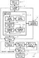
ここで、従来の一般的な符号化方法について説明する。図54はH.261の符号化方式を説明する図であり、概略的には、画像データ入力手段201、動き補償手段202、データ選択手段203、DCT(離散コサイン変換)手段204、量子化手段205、逆量子化手段206、逆DCT手段207、データ記憶手段208、符号化手段209、符号化データ出力手段210などを有した構成となっている。
【0011】
このような構成において、画像データ入力手段201に入力された1フレーム分の画像データは、それが差分モードで符号化される場合は動き補償手段202で処理される。
【0012】
データ選択手段203は、差分モードで符号化される場合においては、動き補償手段202による動き補償後のデータを選択し、差分モードではない場合においては、画像データ入力手段201により与えられるデータそのものを選択する。
【0013】
このデータ選択手段203で選択されたデータは、DCT手段204によって周波数データへ変換され、得られたDCT係数を量子化手段205によって量子化し、符号化手段209で符号化することによりデータが圧縮される。
【0014】
また、量子化されたデータを逆量子化手段206によって逆量子化し、逆DCT手段207によって逆量子化することによって得られたデータは、データ記憶手段208に記憶され、次のフレームのデータでの差分化処理のための前フレームデータとして用いられる。これは、復号処理側で参照可能な前フレームデータは、符号化されたデータから復号されたデータのみであることに対応する。
【0015】
ここで、動き補償処理は任意の大きさの領域で行われるものではなく、マクロブロックと呼ばれる16画素×16画素の正方形領域を単位として行われる。また、DCT処理などの空間周波数への変換処理は、位置に対する情報を分散させてしまうために、動き補償処理は入力された画像に対するDCT処理、量子化処理などが施される前に実行される必要がある。
【0016】
この符号化処理において、DCT処理なども大きな計算量が必要な処理であるが、動き補償処理もまた大きな計算量を必要とする処理である。つまり、動きベクトルを求める処理は、各々のブロックに対し、
【0017】
【数1】
により与えられる誤差Err(i,j)が最小となり、かつ、それが、所定の値よりも小さくなるようなiとjを求めるような処理である。
【0019】
上述の(1)式においては、二乗誤差を評価基準として用いることを想定しており、D(x,y)は、ある座標(x、y)におけるデータ(画素)値を示すものとする。同様に、P(x+i,y+j)における前フレームのデータ(画素)値を示すものとする。ここで、値(i,j)が動きベクトルを表す。また、Lは処理対象とする正方形ブロックの大きさを表す。この演算処理の結果、ある動きベクトル(i,j)に対する差異Err(i,j)が求められる。
【0020】
H.261の符号化方式においては、L=16である。また、1組のiとjの範囲としては、−15から+15の範囲の計算を行う。そのため、単純に実行すれば、(1)式を900回以上の行うことが必要となる。
【0021】
また、この動き補償処理は、マクロブロックという正方形領域を用いた処理であるため、その中の小さな部分において動きがあった場合でも、そのブロック全体の処理が必要となる。また、動き補償においてブロックをコピーする場合、そのブロックの境界に不連続が生じる可能性がある。
【0022】
この演算量の多さや不連続性の改善を図る技術の例として、特開平8−37664号公報に記載の技術「動画像符号化/復号化装置」や特開平10−341441号公報に記載の技術「二次元三角パッチ線格子モデルを用いた動画像の動き推定方法」などがある。
【0023】
特開平8−37664号公報に記載の技術は、その公報に記載された図2に見られるように、入力データから代表点を求め、それらを結ぶ三角形領域を設定し、この代表点の移動より、フレーム間での動きベクトルを求めるものである。この代表点およびそれらを結ぶ三角形領域は、対象となるデータに依存し、任意の位置、任意の大きさに取ることができる。これにより、動き補償の演算量を削減し、かつ、前フレームからの、より滑らかな動きや変形を可能とすることができる。
【0024】
一方、特開平10−341441号公報に記載の技術は、上述の特開平8−37664号公報に記載の技術とは異なり、その公報に記載された図3に示されるように、入力データ全体に対し、マクロブロックを対角線で2分割した二次元三角パッチ線格子モデルと呼ぶ小さな二次元三角形よりなる格子を当てはめる。その後、その公報に記載された図2に示されるように、その三角形領域の頂点を基準に、動きベクトルを計算する。そして、求められた動きベクトルをもとに、その公報に記載された図5(c)に示されるように、三角パッチ線格子が変形させせられる。これにより、最終的には特開平8−37664号公報に記載の技術と同様に、演算量を削減し、前フレームからの、より滑らかな動きや変形を可能とすることができる。
【0025】
【特許文献1】
特開平8−37664号公報
【特許文献2】
特開平10−341441号公報
【0026】
【発明が解決しようとする課題】
しかしながら、特開平8−37664号公報に記載の技術においては、代表点を求めること自体に多くの計算量を必要とし、また、代表点が誤検出された場合は、非常に大きな画質劣化を招くといった問題がある。また、特開平10−341441号公報においても、動きベクトルを求めるに多くの計算量が必要となる。
【0027】
動き補償処理は、動画の圧縮効率を大きく改善するものである。しかし、さまざまな改善手段はあるものの、動き補償処理には依然として非常に大きな計算量、メモリ量を必要とし、たとえば、携帯型情報機器のようなハードウエア能力、電源能力などに大きな制約のある状況下での使用は困難である場合が多い。また、専用ハードウエア化は、それらの課題を改善するものであるが、汎用性、コストの面での新たな問題点が出てくる。
【0028】
また、動画符号化処理が、汎用機器の上で他の処理と並行して行われる場合、他の処理の負荷変動に依存して、動画符号化処理に割り当てられる計算能力を柔軟に変化させることができる方がより好都合である。
【0029】
しかし、従来例のように、動き補償処理が処理の最前段に存在する場合(図54参照)、動き補償処理は符号化処理と一体化しており、負荷変動に対応することは困難であった。また、動き補償処理が処理の最前段に存在するということは、得られた符号化データ量が目標とする符号化データ量ではなく、リトライを行う場合、動き補償処理にまで遡って、多くの処理をやり直す必要があるため、リトライ時の演算量が多くなるという問題もある。
【0030】
そこで本発明は、動画の符号化および復号化を少ない計算量、少ないメモリ量で実現できる画像処理方法および画像処理装置ならびに画像処理プログラムを提供することを目的としている。
【0031】
【課題を解決するための手段】
本発明は、動画データの符号化および復号化を行うものであるが、その符号化および復号化を行うに際して、処理対象となる画像を正方形とすることが前提である。この画像の正方形化を行う際、処理対象画像を1つ以上の正方形領域に分割する方法、もう1つは処理対象画像を正方形に変形させることで1つの正方形領域を生成する方法が考えられるが、本発明では前者、すなわち、処理対象画像を1つ以上の正方形領域に分割する方法を採用する。
【0032】
まず、本発明の画像処理方法について言えば、この画像処理方法の符号化側は、動画を構成する連続した個々のフレーム対応の画像データをフレーム間相関を用いて符号化する画像処理方法であって、その画像処理手順として、フレーム対応の画像データを入力する画像入力ステップと、入力されたフレーム対応の画像データを1つ以上の正方形領域に分割する正方形領域分割ステップと、分割されたぞれぞれの正方形領域を再帰的に三角形領域に分割する再帰的三角形領域分割ステップと、分割された三角形領域を符号化する符号化データ生成ステップと、この符号化データ生成ステップによって生成された個々のフレーム対応の符号化データに対しフレーム間相関を用い、現フレームに対する符号化データを前フレームの符号化データで置換できるか否かを判定し、前フレームの符号化データで置換できると判定された場合は、それを示す情報を出力する符号化データ差分化ステップと、この符号化データ差分化ステップの判定結果に基づいた符号化データを出力する符号化データ出力ステップとを含むことを特徴としている。
【0033】
このような画像処理方法において、前記符号化データ差分化ステップは、前記個々のフレーム対応の符号化データを現フレーム符号化データとし、この現フレーム符号化データと前フレーム符号化データとをそれぞれの対応する三角形領域で比較し、その差異の大きさが所定値未満であるか否かを判定し、差異が所定値未満である場合には、当該三角形領域における現フレーム符号化データを前フレーム符号化データで置換することを示す情報を出力し、差異が所定値以上である場合には、当該三角形領域は現フレームの符号化データを出力するようにしている。
【0034】
また、この画像処理方法において、前記再帰的に分割されたそれぞれの三角形領域を、その元となる正方形領域を根とする2分木で表現し、前記符号化データ差分化ステップは、前記前フレーム符号化データに対応する2分木の最終階層の三角形領域と現フレーム符号化データに対応する2分木の最終階層の三角形領域について、両者の差異を求め、その差異の大きさに基づいて当該三角形領域が前フレームの同じ領域の符号化データで置換できるか否かを判定し、それよりも上位の階層の三角形領域においては、自身を2分割して得られた2つの三角形領域がともに前フレームの同じ領域の符号化データで置換できる場合に、自身の三角形領域も前フレームの同じ領域の符号化データで置換できると判定するようにしている。
【0035】
また、この画像処理方法において、前記前フレーム符号化データで置換することを示す情報は、当該前フレーム符号化データで置換するとされた最上位の三角形領域のみに付されるようにしている。
【0036】
また、本発明の画像処理方法の復号化側は、動画を構成する連続した個々のフレーム対応の画像データが、1つ以上の正方形領域に分割され、そのそれぞれの正方形領域が再帰的三角形領域分割処理されたのち、その分割された三角形領域が符号化され、かつ、当該処理対象となるフレーム対応の画像データがフレーム間相関を用いて符号化されてなり、この符号化データを復号化する画像処理方法であって、その画像処理手順として、符号化データを入力する符号化データ入力ステップと、この符号化データ入力ステップに入力された符号化データを解析する符号化データ解析ステップと、この符号化データ解析ステップによる解析結果に基づいて、前フレーム符号化データを選択するか現フレーム符号化データを選択するかを判定する符号化データ選択判定ステップと、この符号化データ選択判定ステップの判定結果に基づいて、再帰的に三角形領域を合成する再帰的三角形領域合成ステップと、合成された三角形領域により正方形領域を合成する正方形領域合成ステップと、合成された正方形領域から画像データを復元して出力する画像データ出力ステップとを含むことを特徴としている。
【0037】
このような画像処理方法において、前記符号化データ選択判定ステップが行う前フレーム符号化データを選択するか現フレーム符号化データを選択するかの判定は、前フレームデータで置換することを示す情報に基づいて行い、ある三角形領域に前フレームデータで置換することを示す情報が与えられている場合には、当該三角形領域より下の階層の三角形領域全体を、前フレームの同じ領域の符号化データを用いて復号化するようにしている。
【0038】
また、本発明の画像処理装置の符号化側は、動画を構成する連続した個々のフレーム対応の画像データをフレーム間相関を用いて符号化する画像処理装置であって、その構成要素として、画像データを入力する画像入力手段と、入力された画像データを1つ以上の正方形領域に分割する正方形領域分割手段と、分割されたぞれぞれの正方形領域を再帰的に三角形領域に分割する再帰的三角形領域分割手段と、分割された三角形領域を符号化する符号化データ生成手段と、この符号化データ生成手段によって生成された個々のフレーム対応の符号化データに対しフレーム間相関を用い、現フレームに対する符号化データを前フレームの符号化データで置換できるか否かを判定し、前フレームの符号化データで置換できると判定された場合は、それを示す情報を出力する符号化データ差分化手段と、この符号化データ差分化手段の判定結果に基づいた符号化データを出力する符号化データ出力手段とを含むことを特徴としている。
【0039】
このような画像処理装置において、前記符号化データ差分化手段は、前記個々のフレーム対応の符号化データを現フレーム符号化データとし、この現フレーム符号化データと前フレーム符号化データとをそれぞれの対応する三角形領域で比較し、その差異の大きさが所定値未満であるか否かを判定し、差異が所定値未満である場合には、当該三角形領域における現フレーム符号化データを前フレーム符号化データで置換することを示す情報を出力し、差異が所定値以上である場合には、当該三角形領域は現フレームの符号化データを出力するようにしている。
【0040】
また、この画像処理装置において、前記再帰的に分割されたそれぞれの三角形領域を、その元となる正方形領域を根とする2分木で表現し、前記符号化データ差分化手段は、前フレーム符号化データに対応する2分木の最終階層の三角形領域と現フレーム符号化データに対応する2分木の最終階層の三角形領域について、両者の差異を求め、その差異の大きさに基づいて当該三角形領域が前フレームの同じ領域の符号化データで置換できるか否かを判定し、それよりも上位の階層の三角形領域においては、自身を2分割して得られた2つの三角形領域がともに前フレームの同じ領域の符号化データで置換できる場合に、自身の三角形領域も前フレームの同じ領域の符号化データで置換できると判定するようにしている。
【0041】
また、この画像処理装置において、前記前フレーム符号化データで置換することを示す情報は、当該前フレーム符号化データで置換するとされた最上位の三角形領域のみに付されるようにしている。
【0042】
また、本発明の画像処理装置の復号化側は、動画を構成する連続した個々のフレーム対応の画像データが1つ以上の正方形領域に分割され、そのそれぞれの正方形領域が再帰的三角形領域分割処理されたのち、その分割された三角形領域が符号化され、かつ、当該処理対象となるフレーム対応の画像データがフレーム間相関を用いて符号化されてなり、この符号化データを復号化する画像処理装置であって、その構成要素として、符号化データを入力する符号化データ入力手段と、この符号化データ入力手段に入力された符号化データを解析する符号化データ解析手段と、この符号化データ解析手段による解析結果に基づいて、前フレーム符号化データを選択するか現フレーム符号化データを選択するかを判定する符号化データ選択判定手段と、この符号化データ選択判定手段の判定結果に基づいて、再帰的に三角形領域を合成する再帰的三角形領域合成手段と、合成された三角形領域により正方形領域を合成する正方形領域合成手段と、合成された正方形領域から画像データを復元して出力する画像データ出力手段とを含むことを特徴としている。
【0043】
このような画像処理装置において、前記符号化データ選択判定手段が行う前フレーム符号化データを選択するか現フレーム符号化データを選択するかの判定は、前フレーム符号化データで置換することを示す情報に基づいて行い、ある三角形領域に前フレーム符号化データで置換することを示す情報が与えられている場合には、当該三角形領域より下の階層の三角形領域全体を、前フレームの同じ領域の符号化データを用いて復号化するようにしている。
【0044】
また、本発明の画像処理プログラムの符号化側は、動画を構成する連続した個々のフレーム対応の画像データをフレーム間相関を用いて符号化する画像処理方法であって、その画像処理手順として、フレーム対応の画像データを入力する画像入力ステップと、入力されたフレーム対応の画像データを1つ以上の正方形領域に分割する正方形領域分割ステップと、分割されたぞれぞれの正方形領域を再帰的に三角形領域に分割する再帰的三角形領域分割ステップと、分割された三角形領域を符号化する符号化データ生成ステップと、この符号化データ生成ステップによって生成された個々のフレーム対応の符号化データに対しフレーム間相関を用い、現フレームに対する符号化データを前フレームの符号化データで置換できるか否かを判定し、前フレームの符号化データで置換できると判定された場合は、それを示す情報を出力する符号化データ差分化ステップと、この符号化データ差分化ステップの判定結果に基づいた符号化データを出力する符号化データ出力ステップとを含むことを特徴としている。
【0045】
このような画像処理プログラムにおいて、前記符号化データ差分化ステップは、前記個々のフレーム対応の符号化データを現フレーム符号化データとし、この現フレーム符号化データと前フレーム符号化データとをそれぞれの対応する三角形領域で比較し、その差異の大きさが所定値未満であるか否かを判定し、差異が所定値未満である場合には、当該三角形領域における現フレーム符号化データを前フレーム符号化データで置換することを示す情報を出力し、差異が所定値以上である場合には、当該三角形領域は現フレームの符号化データを出力するようにしている。
【0046】
また、この画像処理プログラムにおいて、前記再帰的に分割されたそれぞれの三角形領域を、その元となる正方形領域を根とする2分木で表現し、前記符号化データ差分化ステップは、前記前フレーム符号化データに対応する2分木の最終階層の三角形領域と現フレーム符号化データに対応する2分木の最終階層の三角形領域について、両者の差異を求め、その差異の大きさに基づいて当該三角形領域が前フレームの同じ領域の符号化データで置換できるか否かを判定し、それよりも上位の階層の三角形領域においては、自身を2分割して得られた2つの三角形領域がともに前フレームの同じ領域の符号化データで置換できる場合に、自身の三角形領域も前フレームの同じ領域の符号化データで置換できると判定するようにしている。
【0047】
また、この画像処理プログラムにおいて、前記前フレーム符号化データで置換することを示す情報は、当該前フレーム符号化データで置換するとされた最上位の三角形領域のみに付されるようにしている。
【0048】
また、本発明の画像処理プログラムの復号化側は、動画を構成する連続した個々のフレーム対応の画像データが、1つ以上の正方形領域に分割され、そのそれぞれの正方形領域が再帰的三角形領域分割処理されたのち、その分割された三角形領域が符号化され、かつ、当該処理対象となるフレーム対応の画像データがフレーム間相関を用いて符号化されてなり、この符号化データを復号化する画像処理方法であって、その画像処理手順として、符号化データを入力する符号化データ入力ステップと、この符号化データ入力ステップに入力された符号化データを解析する符号化データ解析ステップと、この符号化データ解析ステップによる解析結果に基づいて、前フレーム符号化データを選択するか現フレーム符号化データを選択するかを判定する符号化データ選択判定ステップと、この符号化データ選択判定ステップの判定結果に基づいて、再帰的に三角形領域を合成する再帰的三角形領域合成ステップと、合成された三角形領域により正方形領域を合成する正方形領域合成ステップと、合成された正方形領域から画像データを復元して出力する画像データ出力ステップとを含むことを特徴としている。
【0049】
このような画像処理プログラムにおいて、前記符号化データ選択判定ステップが行う前フレーム符号化データを選択するか現フレーム符号化データを選択するかの判定は、前フレームデータで置換することを示す情報に基づいて行い、ある三角形領域に前フレームデータで置換することを示す情報が与えられている場合には、当該三角形領域より下の階層の三角形領域全体を、前フレームの同じ領域の符号化データを用いて復号化するようにしている。
【0050】
このように本発明は、画像を正方形領域とした上で処理を行うものであり、その符号化側では、処理対象となる画像データを符号化するに際して、処理対象の画像データを1つ以上の正方形領域に分割し、取り出された正方形を再帰的に三角形領域に分割し、得られたそれぞれの三角形領域の3頂点の画素情報(以下では画素値という)と斜辺中点の画素値を得るようにしている。このとき、再帰的分割処理によって得られるそれぞれの三角形の型は、元の正方形に対する分割の仕方を決めておけば、あとは分割順にしたがって自動的に決めることができる。また、それぞれの三角形の頂点の画素値は正方形の持っている画素値をそのまま継承でき、斜辺中点の画素値も元の正方形から求めることができる。そして、このような再帰的三角形分割処理による三角形の型と保持すべき画素値(斜辺中点画素値)を2分木で表現でき、その2分木に基づいて1次元化された符号化データとして出力することができる。
【0051】
これによれば、処理対象となる画像データを符号化する際、符号化を行う際に保持あるいは伝送すべきデータはごく少量ですみ、それによって、演算を大幅に簡略化することができるとともにメモリの使用量を大幅に減らすことができる。
【0052】
また、本発明ではこの画像処理技術を用いて動画の符号化およびその復号化を行うものであり、その動画符号化は、処理対象となるフレーム対応の画像をフレーム間相関を用いるが動き補償処理は行わずに符号化するものである。このように本発明は、動き補償処理を用いないので、動きベクトルを求めるために多くの計算量、メモリ量を必要としていた従来技術に比べると、計算量やメモリ量を大幅に削減できる効果がある。
【0053】
また、符号化したあとのデータのみを用いてフレーム間の差分を計算するので、これによっても、計算量やメモリ量を削減できる。なお、動き補償を行わないことによる符号化効率の劣化は、本発明の基礎となる画像処理技術である正方形領域を再帰的三角形領域分割することによって得られた2分木のデータ構造により、差異のある部分をそれに最も適したサイズの領域として表現することを可能とすることによって改善できる。
【0054】
つまり、従来例においては、前述したように、処理の単位が16画素×16画素のマクロブックという固定された大きさであったが、本発明においては、可能である限り、大きな領域を前フレームの符号化データで置換できるというような符号化を行う。逆に言うと、差異のある部分をできるだけ小さな領域で表現することによって、トータルとしての符号化効率を改善する効果がある。
【0055】
また、上述したように、本発明の動画符号化で用いられる符号データ差分化処理は、符号化したあとのデータを用いて行われるので、本発明の基礎となる画像処理技術による符号化や、それを基にした個々のフレームのデータ省略処理とは独立して行うことができる。そのため、たとえば、本発明で用いられる符号データ差分化処理を行っている最中に、他の処理負荷が増加して、本発明で用いられる符号データ差分化処理に割り当てられる演算処理量が少なくなった場合、その符号化データ差分化処理を中断し、それまでに処理された結果を直接に符号化出力とすることが可能である。また、他の処理負荷が始めから大きい場合には本発明の符号化データ差分化処理を全く行わないようにすることもできる。このように、システムの処理負荷の大きさに応じて、柔軟に対応することができる。また、符号化したあとのデータを用いて符号化データ差分化処理を行うことは、上述したような種々の効果の他に、最終的に得られた符号化データが目標とするデータと異なるような場合のリトライ処理を行う際の演算量を少なくすることができるという効果も得られる。
【0056】
つまり、従来の技術では、入力された画像データに対して動き補償を行った後に、符号化してその符号化データを出力するという方式では、リトライを行う場合、動き補償処理にまで遡って、再度、動き補償処理を行った後に符号化するというように複数段階の処理をやり直す必要があるが、本発明では、符号化データ差分化処理だけをやり直すだけですむので、リトライを行う場合の演算量を少なくすることができる。
【0057】
また、符号化側からの符号化データを復号する際は、符号化側からの符号化データを解析し、その符号化データが現フレーム対する差分データであるのか、それとも、データ置換の要求されたデータであるのかを判定して、その判定結果に基づいて、三角形領域の合成をおこなうようにしている。このとき、データ置換の要求されたデータであるのか否かの判定は、データ置換の可能な最上位の三角形領域に付されたデータ置換が可能であることを示す情報に基づいて行い、ある三角形領域に対してデータ置換が可能であることを示す情報が与えられている場合には、当該三角形領域より下の階層の三角形領域全体を、そのデータ置換が可能であることを示す情報の付加された三角形領域の符号化データを用いて復号化するようにしているので、効率的な三角形領域の合成が行える。
【0058】
【発明の実施の形態】
以下、本発明の実施形態を図面に基づいて説明する。まず、本発明の基礎となる技術として、処理対象となる画像を1つ以上の正方形領域に分割し、それぞれの正方形領域を再帰的に三角形領域に分割して、分割された三角形領域を符号化する画像処理と、それによって符号化された符号化データを復号化する画像処理について説明し、そのあとで、本発明の動画符号化処理とそれを復号する復号化処理について説明する。
【0059】
図1は本発明に係る画像処理装置の符号化、すなわち、処理対象となる画像を1つ以上の正方形領域に分割し、それぞれの正方形領域を再帰的に三角形領域に分割して、分割された三角形領域を符号化する符号化側の構成を示すブロック図である。その構成を大きく分けると、画像データ入力手段1、正方形領域分割手段2、再帰的三角形領域分割手段3、三角形領域分割制御手段4、符号化データ生成手段5、符号化データ出力手段6を有した構成となっている。
【0060】
画像データ入力手段1は、図2に示すように、個々の画素データを入力する画素データ入力手段101と、入力された画素の色データを各色成分へ分離する色成分分離手段102と、分離された色データに基づき、たとえば、RGBからYUVデータへ変換する色変換手段103と、必要であるならばデータの間引きを行うデータ間引き手段104を有している。なお、この画像データ入力手段1に入力される画像データは、たとえば、カメラからの画像データ、ファイルからの画像データ、何らかの通信手段からの画像データなどが考えられる。
【0061】
再帰的三角形領域分割手段3は、少なくとも、複数種類の三角形型(これについては後述する)を記憶する形状型記憶手段31と、三角形の3つの頂点の画素値および斜辺中点画素値を記憶する頂点画素値記憶手段32と、三角形の斜辺中点の画素値を補う斜辺中点画素値取得手段33と、後述する規則(図11参照)を用いて三角形型を更新する形状型更新手段34と、三角形の3つの頂点の画素値および斜辺中点の画素値を更新する頂点画素値更新手段35とを有している。
【0062】
以下に図1で示した各構成要素の動作について詳細に説明する。
【0063】
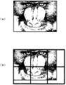
本発明は、処理すべき画像データを正方形とし、それを再帰的に三角形領域へ分割してその三角形領域に対して画像処理を行う。たとえば、画像データ入力手段1から得られた画像データのある1つの色成分が図3(a)のようであるとする。本発明は、これを、図3(b)のように三角形領域の集合として表現する。
【0064】
このように、本発明では処理すべき画像データが正方形であることを前提に処理を行うが、画像データ入力手段1から得られる画像データは必ずしも正方形であるとは限らない。そこで、画像データが正方形ではない場合の処理について説明する。
【0065】
入力された画像データが正方形ではない場合、正方形領域分割手段2によって入力された画像データを1つ以上の正方形領域へ分割する。たとえば、入力された画像データが、図4(a)のような横長の長方形画像である場合、これを図4(b)で示すような複数の正方形領域へ分割する。この時、分割される正方形の1辺に含まれる画素数をLとすると、Lは2のN剰+1であることが望ましい。この理由は後述する。なお、Nは自然数である。
【0066】
このように、もともと正方形でない画像を正方形領域分割手段2によって正方形領域へ分割すると、図4(b)に示すように、画像の端部に重なる正方形部分には画像の存在しない空白部が生じる。また、一般的には、画像データの幅と高さは、Lの整数倍とはならない。この空白部に対する処理と画像データの幅と高さが、Lの整数倍とはならない場合の処理について図5のフローチャートと図6の画像例を参照しながら説明する。
【0067】
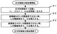
図5は正方形領域分割処理手段2が行う正方形領域分割処理手順を説明するフローチャートであり、まず、分割すべき正方形領域の1辺値としてLを入力する(ステップS1)。ただし、上述したように、Lは2のN剰+1とする(Nは自然数)とする。ここで、当該画像の幅WがLの整数倍ではないとき、当該画像の幅がLの整数倍となるまで0を挿入する(ステップS2)。また、同様に、当該画像の高さHがLの整数倍ではないとき、当該画像の高さHがLの整数倍となるまで0を挿入する(ステップS3)。
【0068】
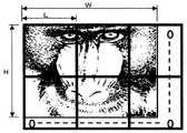
図6は、ある横長の画像に対し、図5で説明した正方形領域分割処理を施した例である。この図6からもわかるように、当該画像の幅WはLの整数倍ではないので、当該画像の幅がLの整数倍であるとして、その余白部に0を補填している。同様に、当該画像の高さHはLの整数倍ではないので、当該画像の高さHがLの整数倍であるとして、その余白部に0を補填している。
【0069】
この図5および図6で説明した例は、画像の幅方向および高さ方向をLの整数倍として、それによって生じる余白部に0を補填するようにした例について説明したが、それ以外にも、たとえば、JPEGなどの処理に見られるように、幅方向においては、当該画像における最も右側の列の画素値を繰り返し、また高さ方向においては、当該画像における最も下側の行の画素値を繰り返すと言うようなものであってもよい。また、JPEG2000などに見られるように、幅方向においては、当該画像における最も右側の列で画像値を折り返す、また高さ方向においては、当該画像における最も下側の行で画像値を折り返すと言うようなものであってもよい。
【0070】
なお、これ以降の処理は、JPEGなどと同様に、この分割された正方形領域のそれぞれにおいて独立した処理となるので、一般性を損なうことなく、画像データは正方形であるとして説明を続ける。
【0071】
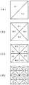
次に上述したように正方形領域に分割されたそれぞれの正方形を三角形に分割する処理について説明する。この三角形に分割する処理は、再帰的三角形領域分割手段3によって行われる。この再帰的三角形領域分割手段3は、それぞれの正方形領域を再帰的に三角形領域へ分割するもので、たとえば、図7(a),(b)に示すように、ある1つの正方形領域は、2つの三角形に分割される。そして、この図7(a),(b)では図示されていないが、分割された三角形はさらにそれぞれ三角形に分割される。
【0072】
この正方形を三角形に分割する方法は二通りあり、その第1の方法としては図7(a)示すような分割の仕方であり、第2の方法としては図7(b)に示すような分割の仕方である。
【0073】
すなわち、正方形の4つの角部の画素値をa,b,c,dとしたとき、図7(a)は第1の方法によって2つの三角形に分割し、図7(b)は第2の方法によって2つの三角形に分割した例であり、これら第1および第2の方法を用いて分割されることによって生成される三角形の型を、それぞれの図中で示したように、#1、#2、#3、#4と表すことにする。
【0074】
ところで、この図7(a),(b)のように分割された三角形を再帰的に分割して得られる三角形は合計で8種あり、その8種類のそれぞれを図8に示すように、#1、#2、#3、#4、#5、#6、#7、#8の型番号を付す。なお、この図8に示される各三角形のそれぞれの頂点に付されたa,b,cはそれぞれその位置における画素値を表しており、また、それぞれの斜辺に付されたdは、その斜辺中点位置における画素値を表すが、これについては後に説明する。
【0075】
このような再帰的三角形領域分割されたそれぞれの三角形の型(三角形型)は相互に関連つけることができる。たとえば、図9に示すように、#6の型の三角形を分割すると、#1と#4の型の三角形が生成される。つまり、本発明の再帰的三角形領域分割処理において、分割処理後の3角形の型は、その元となる三角形の型から自動的に定まるので、出力データの中に三角形の型を保存する必要はない。
【0076】
ところで、上述した図7により正方形を三角形に分割する方法(第1の方法および第2の方法)について説明をしたが、このとき、正方形の4頂点の位置の画素値がどのようにして三角形に継承されるのかを説明する。
【0077】
ここで、正方形の4頂点の画素値がa,b,c,dであったとすると、この正方形の4頂点の画素値a,b,c,dの継承パタンとしては図7(a),(b)で説明した分割の仕方によって2種類がある。
【0078】
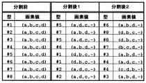
図10はこの継承規則を示したものである。たとえば、正方形が図7(a)のような方法(第1の方法)で三角形に分割されたとすると、図10の上段に示すように、分割前(正方形)の型をここでは#0と表すものとすると、この正方形の4頂点の画素値(a,b,c,d)は、三角形分割において得られた#1型の三角形の画素値として(a,b,c,−)が継承され、#2型の三角形の画素値として(b,c,d,−)が継承される。
【0079】
一方、正方形が図7(b)のような方法(第2の方法)で三角形分割されたとすると、図10の下段に示すように、分割前(正方形)の型をここでも#0と表すものとすると、この正方形の4頂点の画素値(a,b,c,d)は、三角形分割において得られた#3型の三角形の画素値として(a,c,d,)が継承され、#4型の三角形の画素値として(a,b,d,−)が継承される。
【0080】
なお、本発明においては、それぞれの三角形の3頂点の画素値に加え、三角形の斜辺中点の画素情報も加えた4つの画素値を考慮するが、図10の中で、ハイフン「−」で示した部分が斜辺中点の画素値であり、このハイフンはそれが不明であること、あるいは、その画素値の設定を必要とすることを示している。
【0081】
図11は図8で示した8種類の三角形をさらに分割したときの画素値の継承規則を示すものであり、この図11に示されるように、分割前にある型(#1から#8)であった三角形は、それを分割すると、それぞれ2つの型の三角形となるが、そのときの画素値はこの図11に示すように継承される。なお、この図11においても、ハイフン「−」で示した部分が斜辺中点の画素値であり、このハイフンはそれが不明であること、あるいは、その画素値の設定を必要とすることを示している。
【0082】
この図11によれば、たとえば、頂点の画素値がa,b,c、斜辺中点の画素値がdである#6型の三角形を分割すると、#1型と#4型の2つの三角形に分割され(図9参照)、#1型の三角形の画素値は(a,d,c,−)、#4型の三角形の画素値は(c,d,b,−)となる。
【0083】
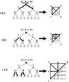
以上の再帰的三角形分割処理のまとめを図12により説明する。ある1つの正方形を、たとえば、#1と#2の型の三角形に分割するものとする。この、#1と#2の型の三角形は、#1型についてはさらに#5型と#6型に分割され、#2型についてはさらに#7型と#8型に分割される。この分割された三角形は、さらに、より小さな三角形に分割される。なお、この再帰的な分割処理は、斜辺中点に画素が存在する限りは次々と分割可能であるが、分割限界に達しなくても所定の段階で分割処理を終了することも可能である。どの段階まで分割するかは予め設定しておくことができる。
【0084】
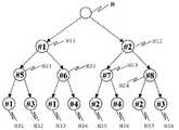
上述した再帰的三角形分割処理は、図13に示すような2分木で表現することができる。図13において、○の中の数字は三角形の型を示す。最も上部の内部に数字の無い○を正方形とし、これをルート(根)Rとした2分木が生成される。
【0085】
ルートRから生成される2つのノード(節)N11,N12の三角形型は、図7(a),(b)の2つの分割方法(第1の方法または第2の方法)に対応しているが、これが決定されてしまえば、それぞれのノードを2分割してできる三角形は、図11に示すような継承規則により一意に定まる。たとえば、#1型を持つ三角形は、図11からわかるように、#5型と#6型の三角形に2分される。同様に、#5型を持つ三角形は、図11からわかるように、#1型と#3型の三角形に2分される。
【0086】
以降、記述の簡略化のため、三角形型がT、3頂点の画素値がa,b,cであって、斜辺中点の画素値がdである三角形を、T(a,b,c,d)と表す。たとえば、三角形型が#6でその3頂点の画素値がa,b,cであって、斜辺中点の画素値がdである三角形は、#6(a,b,c,d)で表され、それは、#1(d,b,c,−)と#4(a,d,c,−)へ分割されるというように表される。
【0087】
この例から明らかなように、このそれぞれの三角形を分割した後の三角形において、ハイフンで示した不定である斜辺中点の画素値を補うことにより、図11の継承規則を用いて三角形領域分割を再帰的に行うことができる。
【0088】
これは、前述の従来技術の項で引用した特開平9−191409号公報に記載された技術のように、一つの三角形を表現するために、3つの頂点のX座標値が3個、Y座標値が3個、3つの頂点の画素値として3個の合計9個の画素情報を必要としそれを保持する必要のあるものに比較して、ワーストケースにおいて、1/9のデータ量である。
【0089】
以上より、図1に示した再帰的三角形領域分割手段3は、少なくとも、#1型1から#8型の8通りの三角形型を記憶する形状型記憶手段31と、三角形の3つの頂点の画素値および斜辺中点の画素値を記憶する頂点画素値記憶手段32と、三角形の斜辺中点画素値を補う斜辺中点画素値取得手段33と、図11に示す継承規則用いて三角形型を更新する形状型更新手段34と、三角形の3つの頂点の画素値および斜辺中点の画素値を更新する頂点画素値更新手段35により、再帰的に三角形領域を分割することができる。
【0090】
以上の再帰的三角形領域分割処理を具体的な数値例を用いて説明する。説明を簡単にするために、図14に示すように、1辺の画素数LがL=3(この場合は、Lが2のN乗+1であるという条件において、N=1とした場合である)の正方形を例にとる。なお、図14において、それぞれの画素を黒丸で表し、それぞれの画素に付された数値はその画素における画素値を表している。
【0091】
このような正方形に対し、図7(a)で示したような方法(第1の方法)で2分割したとすると、図15(a)に示すように、2つの三角形に分割される。この左上の三角形は、#1型の三角形であり、その頂点の画素値は(3,9,1)であるので、#1(3,9,1,−)と表され、これに斜辺中点の画素値7を補うことにより、#1(3,9,1,7)という情報を生成することができる。
【0092】
このような情報が生成されたら、この情報を用い、図16のフローチャートに示す手順で分割後の三角形を得る。すなわち、現在の型情報を用いて図11で示した継承規則の検索を行い、分割後の2つの三角形の情報を求める(ステップS21)。そして、図11で示した継承規則の情報に基づき、現三角形の4つの画素値の並べ替えを行い、2つの新三角形を得る(ステップS22)。
【0093】
つまり、この例では、図17に示すように、#1(3,9,1,7)の情報を有する三角形は、#5(3,7,1,−)と、#6(3,9,7,−)に分割されることになる。これを示したものが、図15(a),(b)であり、#1(3,9,1,−)の情報を有する三角形は、その斜辺中点に7の画素値を補填し、それを2分割すると、#5(3,7,1,−)の情報を有する三角形と#6(3,9,7,−)の情報を有する三角形が得られる。以降、これら三角形のそれぞれの斜辺中点の画素値として、図15(c)に示すように、#5型の三角形については5を補填し、#6型の三角形T12については4を補填するという処理を行うことにより再帰的三角形領域分割を行う。
【0094】
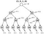
以上の図14から図17で説明した処理は、図18に示すような2分木で表現できる。この図18の2分木表現も図13で示した2分木表現と同様に、2分木の○の中に示した三角形型は、その上位の型から一意に定まるために、データとして出力する必要はなく、その○の下に示した斜辺中点の画素値のみを補うことにより、より下位の三角形領域分割を行うことができる。
【0095】
この図18は、図14で示した正方形を三角形領域分割する場合の2分木表現であり、ルートRに相当する正方形は図14からもわかるように、その4頂点の画素値は(3,9,1,8)であって、このような正方形を図15(a),(b),(c)で説明したような三角形領域分割処理を行ったものである。
【0096】
このように、処理対象となる画像データに対し、最初の正方形の4頂点の画素値、それを最初に3角形分割したときの三角形の型、分割された三角形の斜辺中点の画素値の連鎖の3種のデータによって、正方形領域の画像を表現することができる。
【0097】
なお、このデータのうち、正方形を最初に三角形に分割する際、図7(a),(b)の第1の方法または第2の方法のいずれかで行うかを固定することは可能である。また、正方形領域の1辺に含まれる画素数Lは、2のN剰+1(Nは自然数)となるような条件を満たすようにすると、分割された三角形の斜辺中点には必ず画素が存在する。このため、処理を容易にするためには、正方形領域の1辺に含まれる画素数Lが2のN剰+1(Nは自然数)であることが望ましい。
【0098】
以上のような処理の結果、たとえば図19に示すように、ある画像が複数の正方形領域に分割されている場合、そのそれぞれの正方形領域は、図20に示されるような複数の2分木に変換されることになる。
【0099】
ところで、2分木として表現された画像データを、伝送、記録するためには、それを1次元のデータ列に変換する必要がある。その順序には幾つもの方法が考えられるが、たとえば、以下のような2種の方法も可能である。
【0100】
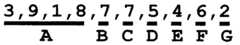
図21は、2分木の幅方向優先の出力方法を示したものである。これは数字の下にアルファベットA,B,C,・・・で示した順番(アルファベット順)にデータが1次元化される。たとえば、最初に、ルートRとして正方形のデータ(4頂点の画素値)Aが出力され、その後、このルートRの下位の同じ深さのノードN11、N12のデータ(斜辺中点の画素値)B,Cが出力され、さらに、その後、ノードN11,N12の下位の同じ深さのノードN21,N22,N23,N24のデータ(斜辺中点の画素値)D,E,F,Gが出力される。
【0101】
図22は、この方法により1次元化されたデータの結果を示すものであり、アルファベットA,B,C,・・・の順に、それぞれのアルファベットA,B,C,・・・に対応した画素値が出力される。
【0102】
図23は、2分木の深さ方向優先の出力方法を示したものである。これも図21と同様にアルファベットA,B,C,・・・で出力の順番を示してある。この場合、ルートRのデータAを出力したあと、ノードN11のデータBを出力し、その後は、それの下位にあたるノードN21のデータCの出力が行われる。このように、2分木の底に到達するまでの出力が行われると、ノードN22のデータDの出力が行われる。そして、今度は、ノードN12のデータEの出力が行われ、続いて、そのノードN12の下位にあたるノードルN23のデータFを出力するというようなデータ出力順序となる。
【0103】
図24は、この方法により1次元化されたデータの結果を示すものであり、アルファベットA,B,C,・・・の順に、それぞれのアルファベットA,B,C,・・・に対応した画素値が出力される。
【0104】
以上のようにして、処理対象となる画像データの符号化処理が終了する。これによって符号化されたデータは、たとえば、図21または図23示されるような2分木のデータ構造となっており、その2分木に基づいて、図22または図24のようなデータ形式で出力される。
【0105】
以上説明した符号化処理をフローチャートにまとめたものが図25である。各部の詳細については説明済みであるので、ここでは概略を説明する。
【0106】
図25において、まず、正方形領域分割処理を行う(ステップS31)。これは、図3から図6で説明したように、処理対象となる画像データを1つ以上の正方形領域へ分割する処理であり、この正方形領域分割処理によって得られたそれぞれの正方形について符号化処理を行うが、すべての正方形領域を符号化したか否かを判断し(ステップS32)、すべての正方形に対してすでに符号化されていれば処理が終了したものとするが、符号化されていなければ、その正方形の4頂点画素値を出力する(ステップS33)。
【0107】
そして、三角形分割処理が終了したか否かを判断し(ステップS34)、終了していれば、ステップS32に戻り、終了していなければ、すべての三角形を符号化したかを判断する(ステップS35)。ここで、すべての三角形の符号化が終了していなければ、斜辺中点の画素値を出力し(ステップS36)、三角形領域更新処理を行い(ステップS37)、ステップS35に戻る。
【0108】
そして、すべての三角形の符号化が終了し、かつ、三角形分割処理が終了し、さらに、すべての正方形領域の符号化が終了していれば、その画像に対する符号化処理を終了する。
【0109】
以上の説明は処理対象となる画像データを符号化する処理についての説明であるが、そのおおまかな処理としては、処理対象の画像データを正方形領域として取り出し、取り出された正方形を再帰的に三角形領域に分割し、得られたそれぞれの三角形領域の3頂点の画素値と斜辺中点の画素値を得るようにしている。このとき、再帰的分割処理によって得られるそれぞれの三角形の型は、元の正方形を2分割の仕方を決めておけば、以降は分割順に従って自動的に決めることができる。また、それぞれの三角形の頂点の画素値は正方形の持っている画素値をそのまま継承できるので、斜辺中点の画素値を元の正方形から求めれば、画像全体を図18に示すような2分木で表現でき、それを図21と図22または図23と図24に示すように1次元化して出力することができる。
【0110】
このような処理を行うことにより、処理対象となる画像データを表現するために保持すべきデータはごく少量ですみ、それによって、演算を大幅に簡略化することができるとともにメモリの使用量を大幅に減らすことができる。
【0111】
次に、符号化されたデータを復号化する処理について説明する。図26は本発明の基礎となる画像処理装置の復号化側の構成を示すブロック図である。この復号化側の構成としては、大きく分けると、符号化データ入力手段11、符号化データ解析手段12、再帰的三角形領域合成手段13、三角形領域合成制御手段14、正方形領域合成手段15、画像データ出力手段16を有している。
【0112】
再帰的三角形領域合成手段13は、少なくとも、分割された三角形の型(前述の符号化の説明においては#1型から#8型の8種類としているので、ここでも#1型から#8型の8種類とする)の三角形型を記憶する形状型記憶手段131と、三角形の3つの頂点の画素値および斜辺中点画素値を記憶する頂点画素値記憶手段132と、三角形の斜辺中点の画素値を補う斜辺中点画素値取得手段133と、前述の図11の継承規則を用いて三角形型を更新する形状型更新手段134と、三角形の3つの頂点の画素値および斜辺中点の画素値を更新する頂点画素値更新手段135とを有している。
【0113】
また、符号化データ入力手段11は、図1で示した符号化データ出力手段6からの符号化データ(たとえば、図22や図24に示したような符号化データ)を、伝送路や記憶媒体から入力する。この符号化データ入力手段11に入力される符号化データとしては、図27(a)に示されるように、最初に、正方形の4頂点の画素値が入力される。たとえば、符号化データとして図24を例にとれば、まず、図24で示す符号化データにおける下線部Aの部分が読み込まれ、正方形の4頂点の画素値(3、9、1、8)が復元される。その後、図24の下線部Bに対応する画素値(7)が読み込まれ、図27(a)に示すような2分木の太線の部分が復元される。またそれは、正方形領域の太線部分に対応する。以降、次々にデータ(画素値)が読み込まれ、図27(b),(c)のように、データの2分木の太線部分が復元され、それによって、正方形領域の太線部分が復元される。
【0114】
図28は、図27の処理内容をプログレッシブな復元の立場から説明したものである。図22で示す符号化データフォーマットによれば、最初に図28(a)のように2分木の上位層のみが復元され、続いて、同図(b)のように2分木の次の階層が復元され、さらに、同図(c)のように2分木のさらに次の階層が復元されというように、2分木の階層ごとに順次復元され、最終的には同図(d)に示すように、2分木の底までの復元がなされる。
【0115】
これによって、処理対象となる画像は、2分木の階層ごとの復元に伴って、順次、大きく、あるいは、解像度が上がったものとなる。
【0116】
なお、たとえば、図28(a)のようなデータ量が少なく小さい画像をそのまま最終画像と同じように拡大しようとすると、解像度の小さい画像となる。すなわち、これは、画像の見え方と言う観点で言えば、画像全体を縮小表示したものであると考えることができる。あるいは、画像サイズを元データと同じとした場合は、それを低い解像度で示したものであると考えることもできる。
【0117】
仮に、画像全体を低い解像度で表現したものであると考える場合、各々の三角形領域は拡大されることになる。この時、三角形領域の内部は、その3頂点の画素値を用いて平面として内挿することにより求めることもできる。勿論、その周辺の三角形領域のデータを用いて、より高次の推定を行うことも可能である。
【0118】
3頂点の画素値を用いて平面として内挿する場合は、図29のような方法を用いることが可能である。この図29について簡単に説明する。三角形の3頂点への位置ベクトルをa,b,c(a,b,cそれぞれの上に→が付される)とし、その頂点における画素値をA,B,Cとする。ここで、画素値を求めるべき位置(pとする)の位置ベクトルをp(pの上に→が付される)とし、この位置ベクトルp(pの上に→が付される)が、
【0119】
【数2】
で与えられるものとする。なお、画素値を求めるべき位置pがその三角形領域の内部であるためには、x、y、zは0以上の実数または重み係数であり、かつ、
x+y+z=1 (3)
の条件を満たす必要がある。このx,y,zを用い、位置pにおける画素値Pは、
P=xA+yB+zC (4)
により求められる。
【0121】
ところで、前述の実施形態1における図21、図22または図23、図24で示したデータの1次元化方法は、画像データの内容とは無関係なものである。しかし、符号化方法あるいは記憶媒体からのデータの読み出し方法を変えることにより、関心領域あるいはROI(Region Of Interest)を優先的に高画質化することができる。
【0122】
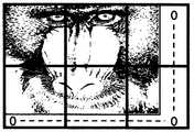
たとえば、図30に示すように、2分木の中の斜線を施した部分を優先的に伝送あるいは読み出すとする。仮に、この2分木の階層の深い部分が、図31に示すように、本発明の実施形態1および実施形態2の説明で用いている画像例としての猿の顔画像の目の部分であるとする。そうすると、図30の2分木の浅い階層の復元処理では図32(a)のように、画像全体が低解像度で復元されたものが、階層が深くなるに連れ、図32(b)のように、先ず目の部分から高解像度化が進行し、最終的に、図32(c)のように全体が高解像度化されるというような表示が可能である。勿論、このような表示は途中の段階で中止することもできる。
【0123】
このように、2分木で表されるデータの伝送あるいは読み出し順に、関心領域あるいはROIに基づいて優先度を設定することによって、画像全体の中のある特定部分のみをいち早く高解像度で表示させることができる。
【0124】
これによって、多数の画像データの中から所望とする画像データを検索したり画像データの分類を行うような場合、個々の画像の特徴的な部分のみをいち早く高解像度で表示させることができるので、検索や分類を効率よく行うことができる。また、このとき、個々の画像の内容がわかった段階で表示処理を中止し、それ以降の表示処理を行わないようにすることもできる。
【0125】
以上説明した復号化処理をフローチャートにまとめたものが図33である。各部の詳細については説明済みであるので、ここでは概略を説明する。
【0126】
図33において、まず、すべての正方形領域を復号化したか否かを判断し(ステップS41)、すべての正方形領域の復号化が終了していなければ、その正方形の4頂点画素値を復号する(ステップS42)。そして、三角形合成処理が終了かを判断し(ステップS43)、終了していれば、ステップS41に戻り、終了していなければ、すべての三角形を合成したかを判断する(ステップS44)。そして、すべての三角形の合成が終了していなければ、斜辺中点の画素値を復号し(ステップS45)、三角形領域合成処理を行い(ステップS46)、ステップS44に戻る。
【0127】
そして、すべての正方形領域の復号化が終了していれば(ステップS41)、正方形領域合成処理を行い(ステップS47)、復号化処理を終了する。
【0128】
このステップS47による正方形領域合成処理された画像データは、図26で示した画像データ出力手段16によって出力処理される。この画像データ出力手段16は、図34に示すように、色データ入力手段161、間引きデータ復元手段162、色変換手段163、画素データ復元手段164を有した構成となっており、復元された画像データから、画像幅、画像高さを正方形の1辺の整数倍にするために補填されたデータを取り除き、元の画像を出力する。なお、この画像データ出力手段16が行う画像データ出力処理には、ノイズ低減処理であるとか、何らかの後処理などが含まれても良い。
【0129】
次にこれまで説明した画像処技術を基に、本発明の画像処理方法および画像処理装置ならびに画像処理プログラムについて説明する。
【0130】
本発明では、上述したような画像処理技術において用いた2分木のデータ構造をもとに、フレーム間相関を用いることで動画符号化およびその復号化を行うものである。なお、本発明は、フレーム間相関を用いるが動き補償は行わないのが特徴であり、また、動画符号化処理はこれまで説明した本発明の基礎となる画像処理技術における符号化の後処理として実行されるものである。以下、詳細に説明する。
【0131】
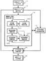
図35は本発明の画像処理装置の符号化側の構成を示すもので、その構成を大きく分けると、画像データ入力手段1、正方形領域分割手段2、再帰的三角形領域分割手段3、三角形領域分割制御手段4、符号化データ生成手段5、符号化データ出力手段6、符号化データ差分化手段20(符号化データ記憶手段7、前フレーム符号化データ記憶手段8、符号化データ比較手段9、符号化データ選択手段10からなる)を有した構成となっている。
【0132】
この図35の構成は図1で示した構成に対して、符号化データ生成手段5と符号化データ出力手段6との間に、符号化データ差分化手段20としての符号化データ記憶手段7、前フレーム符号化データ記憶手段8、符号化データ比較手段9、符号化データ選択手段10が設けられている点が異なるだけで、その他は図1と同じ構成であるので、同一構成要素についての説明はここでは省略する。
【0133】
符号化データ記憶手段7は符号化データ生成手段5からの符号化データ、つまり、本発明の基礎となる画像処理技術において符号化された符号化データを一時的に記憶するものである。
【0134】
前フレーム符号化データ記憶手段8は、符号化データ出力手段6から出力された前フレームの符号化データを記憶するものである。この前フレーム符号化データ記憶手段8に記憶される前フレーム符号化データは、符号化データ記憶手段7に記憶されている前フレームに対応する符号化データそのものではなく、たとえば、符号化データ選択手段10で現フレームデータが選択された場合は、その現フレームデータによって前フレーム符号化データ記憶手段8の内容が更新され、それによって、その更新データが前フレームの符号化データとなる。
【0135】
符号化データ比較手段9は、符号化データ記憶手段7に記憶された現フレーム符号化データと前フレーム符号化データ記憶手段8に記憶された前フレーム符号化データとを比較し、その差異が所定値未満であるか否かを判定し、所定値未満であると判断された場合は、現フレームの符号化データを前フレームの符号化データで置換する。
【0136】
符号化データ選択手段10は、現フレーム符号化データか前フレーム符号化データのいずれかを選択するもので、符号化データ比較手段9の比較判定結果に基づき、差異が所定値未満の場合は、置換された符号化データ(前フレームの符号化データ)を選択し、差異が所定値以上である場合は現フレーム符号化データを選択する。
【0137】
符号化データ出力手段6は、符号化データ選択手段10で選択結果を当該フレームの符号化データ(1次元配列化されたデータ)として出力する。
【0138】
図36は画像を1つ以上の正方形領域に分割して、分割されたそれぞれの正方形領域の符号化を行う処理手順を示すもので、図37は分割されたある1つの正方形領域内における符号化手順を示すものであり、これらのフローチャートは、先に説明した本発明の基礎となる画像処理技術における符号化処理の説明に用いた図25のフローチャートを、画像を1つ以上の正方形領域に分割して、それぞれの正方形領域の符号化を行う処理手順と、分割されたある1つの正方形領域内における符号化を行う処理手順とに分けて示すものである。
【0139】
この図36および図37の処理手順は基本的には図25と同じであるが、図36および図37においては、切り出されたある1つの正方形領域内を符号化する処理が終了したあと、前フレームの符号化データとの差異を出力する処理が追加されている。なお、この処理についての詳細は後述する。
【0140】
図36において、まず、正方形領域分割処理を行う(ステップS51)。これは、図3から図6で説明したように、処理対象となる画像データを1つ以上の正方形領域へ分割する処理であり、この正方形領域分割処理によって得られたそれぞれの正方形について符号化処理を行うが、すべての正方形領域を符号化したか否かを判断し(ステップS52)、すべての正方形に対してすでに符号化されていれば符号化処理が終了したものとするが、すべての正方形領域の符号化がなされていなければ、その正方形領域の4頂点画素値を符号化データ記憶手段7に出力(ステップS53)するとともに、その正方形領域内の符号化処理(図37参照)を行う(ステップS54)。そして、その正方形領域内の符号化処理が終了すると、前フレームの符号化データとの差異を符号化する処理を行う(ステップS55)。なお、この前フレームの符号化データとの差異を符号化する処理の具体例については図44から図47を参照して後に説明する。
【0141】
図37は図36におけるステップS54の処理、つまり、ある1つの正方形領域内の符号化処理手順であり、まず、ある1つの正方形領域における2分木の全階層について符号化したかを判断し(ステップS61)、全階層の符号化が終了していれば符号化処理を終了し、全階層の符号化が終了していなければ、その階層のすべての三角形領域を符号化したかを判断する(ステップS62)。
【0142】
ここで、その階層のすべての三角形領域の符号化が終了していれば、ステップS61に戻る。また、その階層のすべての三角形領域の符号化が終了していなければ、その三角形領域の斜辺中点画素値を取得する(ステップS63)。そして、その取得した斜辺中点画素値を符号化し、符号化データ記憶手段7に出力し(ステップS64)、ステップS62に戻り、その階層のすべての三角形の符号化が終了していなければ、ステップS62以降の処理を繰り返し、その階層のすべての三角形領域の符号化が終了していれば、ステップS61に戻って、全階層の符号化を終了したか否かを判断し、全階層の符号化を終了していれば、符号化処理を終了し、全階層の符号化を終了していなければ、ステップS62以降の処理を繰り返す。
【0143】
ここで、図35に示した符号化データ差分化手段20の処理、つまり、符号化データ生成手段5によって生成された個々のフレーム対応の符号化データに対し、フレーム間相関を用い、現フレームに対する符号化データを前フレーム符号化データで置換できるか否かを判定し、前フレーム符号化データで置換できると判定された場合は、それを示す情報を出力する処理について説明する。
【0144】
この処理は、前フレーム符号化データ記憶手段8に記憶された前フレーム符号化データと、符号化データ記憶手段7に一時的に記憶された現フレーム符号化データとの比較を符号化データ比較手段9が行って、その比較結果に基づいた符号化データを符号化データ選択手段10が選択して出力するもので、これは、前述した2分木で示すデータ構造の最終階層から、上位の階層に向かって行われる。
【0145】
この2分木における最終階層の三角形領域は、それ以上分割できない三角形領域であり、斜辺中点画素値を考慮する必要がないので、3つの頂点の画素値で構成される。したがって、この最終階層の三角形領域の前フレームと現フレームとの比較は、それぞれの3頂点画素値の比較で済むため、下記の(5)式のような単純な計算式で両者の差異Errを求めることができる。
【0146】
【数3】
この(5)式において、Diは現フレームのある三角形領域の画素値(iは3つの頂点の位置を表すので1から3の値をとる)、Piは前フレームの同じ三角形領域の画素値であり、iは同じく1から3の値をとる。この(5)式を前述した従来技術の説明で用いた(4)式と比べると、計算が単純であり計算量が大幅に少ないことがわかる。
【0148】
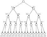
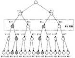
ここで、具体例を参照しながら説明する。この具体例の説明で用いる2分木を図38に示す。この図38に示す2分木は、ある1つの正方形領域について図39の(a)〜(d)に示すような三角形領域分割処理を行った場合に生成されるものであり、ここでは、説明の都合上、2分木を構成するそれぞれの三角形領域に付される符号(型番号)は、これまでの説明で用いた2分木(たとえば、図13など)とは異なった符号が付されている。
【0149】
この場合、正方形を2分割して得られた第1階層の2つの三角形領域に#10,#11の型番号を付し、この第1階層の三角形領域#10,#11をそれぞれ2分割して得られた第2階層の4つの三角形領域に#20,#21,#22,#23の型番号を付し、この第2階層の三角形領域#20,#21,#22,#23#をそれぞれ2分割して得られた第3階層の8つの三角形領域に#30,#31,#32,#33,#34,#35,#36,#37の型番号を付し、この第3階層の8つの三角形領域#30,#31,#32,#33,#34,#35,#36,#37をそれぞれ2分割して得られた第4階層の16個の三角形領域に#40,#41,#42,・・・,#49,#4a,#4b,#4c,#4d,#4e,#4fの型番号を付すことにする。
【0150】
このような第1階層から第4階層の4つの階層で構成される2分木として表現された画像データを、1次元のデータ列に変換する。ここでは、図40で示すように2分木の幅方向優先の出力方法によって、データ(各三角形領域の斜辺中点画素値)を出力、すなわち、第1階から第4階層において、それぞれの階層ごとに太線で示す矢印方向に沿ってデータ(各三角形領域の斜辺中点画素値)を出力すると、図41のような1次元のデータ列が得られる。
【0151】
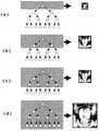
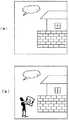
図42はここで用いられる画像例を示すもので、(a)はある1つの正方形領域における前フレーム画像、(b)はその現フレーム画像である。この図42からもわかるように、現フレーム画像が前フレーム画像と異なるのは、画像の左下部分に人間が存在している点だけであり、その他は何ら変化していない。
【0152】
この図42に示す画像例の正方形領域を再帰的三角形領域分割したものが図43(a)、(b)である。この図43(a)、(b)の再帰的三角形領域分割は、図39に対応するものであるので、図43(a)の前フレーム画像および(b)の現フレーム画像は、それぞれ図38のような2分木のデータ構造として表される。
【0153】
ここで、図43(a)、(b)における最終階層(第4階層)の三角形領域、つまり、図38の2分木における第4階層の16個の三角形領域#40,#41,#42,・・・,#49,#4a,#4b,#4c,#4d,#4e,#4fそれぞれについて、上述の(5)式を用いて、前フレームとデータと現フレームデータとの差異Errを求め、求められたそれぞれの差異Errが所定値未満であるか否かを判定する。
【0154】
この判定の結果、この場合、#42,#43,#48,#49の4つの三角形領域だけが前フレーム画像の対応する三角形領域と差異Errが所定値以上であると判定される。これを2分木で表したものが図44である。この場合、図44における破線枠で囲った第4階層の三角形領域のうち、#42,#43,#48,#49の4つの三角形領域(斜線が施されている)だけが前フレーム画像の対応する三角形領域と差異が所定値以上異なっていると判定される。
【0155】
これによって、#42,#43,#48,#49の4つの三角形領域は前フレームの符号化データを用いることはできない(前フレームの符号化データで置換することはできない)と判定され、それ以外の三角形領域は、前フレームの符号化データで置換できると判定される。
【0156】
このようにして、最終階層(第4階層)のそれぞれの三角形領域において(5)式を計算して、求められた差異Errが所定値以上か否かの判定を行えば、それより上位の階層については、(5)式を用いた比較計算を行う必要はなく、自身を2分割して得られた三角形領域(自身から下位に伸びる2つの枝の三角形領域)の結果に基づいて、前フレーム符号化データで置換できるか否かの判断が行える。これについて、図45、図46、図47を用いて説明する。
【0157】
図45は第3階層に対して第4階層の結果を用いて前フレーム符号化データで置換できるか否かの判断を行った結果を示すものである。この場合、自身の三角形領域#30,#31,・・・,#37の三角形領域を表すノードから下に伸びる2つの枝で示される2つの三角形領域が前フレーム符号化データで置換可能であれば、自身も置換可能であると判定され、2つの枝で示される2つの三角形領域の一方が置換可能でなければ、自身も置換可能ではないと判定される。
【0158】
すなわち、この第3階層においては、#30の三角形領域は、それよりも下位の#40、#41の2つの三角形領域がともに置換可能であるので、自身(#30の三角形領域)も置換可能であると判定され、同様に、#32、#33、#33、#35、#36、#37の三角形領域も、自身よりも下位の2つの三角形領域がそれぞれともに置換可能であるので、自身も置換可能であると判定される。
【0159】
これに対して、#31の三角形領域は、それよりも下位の#42、#43の2つの三角形領域がともに置換可能ではないので、自身(#31の三角形領域)も置換可能ではないと判定される。同様に、#34の三角形領域は、それよりも下位の#48、#49の2つの三角形領域がともに置換可能ではないので、自身(#34の三角形領域)も置換可能ではないと判定される。
【0160】
続いて、第2階層について同様の判定を行う(図46参照)。この第2階層においては、#20の三角形領域は、それよりも下位の#30、#31の2つの三角形領域のうち、#31の三角形領域が置換可能でないので、自身(#20の三角形領域)も置換可能でないと判定され、同様に、#22の三角形領域も、自身よりも下位の#34、#35の2つの三角形領域のうち、#34の三角形領域が置換可能でないので、自身(#22の三角形領域)も置換可能でないと判定される。
【0161】
これに対して、#21の三角形領域は、それよりも下位の#32、#33の2つの三角形領域がともに置換可能であるので、自身(#21の三角形領域)も置換可能であると判定され、同様に、#23の三角形領域は、それよりも下位の#36、#37の2つの三角形領域がともに置換可能であるので、自身(#23の三角形領域)も置換可能であると判定される。
【0162】
続いて、第1階層について同様の判定を行う(図47参照)。この第1階層においては、#10の三角形領域は、それよりも下位の#20、#21の2つの三角形領域のうち、#20の三角形領域が置換可能でないので、自身(#10の三角形領域)も置換可能でないと判定され、同様に、#11の三角形領域も、自身よりも下位の#22、#23の2つの三角形領域のうち、#22の三角形領域が置換可能でないので、自身(#11の三角形領域)も置換可能でないと判定される。
【0163】
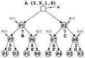
以上の処理がなされることによって、処理対象となっているある1つの正方形領域の現フレーム符号化データは、その一部が前フレーム符号化データで置き換えることができる。以上のような処理がなされたあとの現フレーム符号化データを2分木で表したものが図48である。
【0164】
この図48において、四角で示したノードで示される三角形領域は、それ以下の階層すべてを前フレーム符号化データの2分木の同じ位置の符号化データで置換できることを示している。この例では、#21、#23、#30、#35の三角形領域は、前フレーム符号化データの2分木の同じ位置の符号化データで置換できる。
【0165】
この図48に示される2分木構造の符号化データに対し、図40と同様のデータ読み出しが行われることによって、1次元のデータ配列を生成することができる。
【0166】
図49は図48に示した2分木を第1階層から第4階層までそれぞれの階層ごとに図示の太線矢印で示すような方向にデータ読み出しを行う例を説明する図であり、これを縦に並べて示したものが図50である。
【0167】
この図50は先に説明した図41の1次元化されたデータ配列に対応するものである。この図50の右端に示される四角で囲った“0”または“1”の1ビットのデータは、符号化データの置換がなされているか否かを示すもので、“0”が与えられた三角形領域はデータ置換がなされていないことを示し、“1” が与えられた三角形領域はそれ以降において符号化データ置換がなされていることを示している。
【0168】
この例では、#10、#11,#20、#22、#31、#34、#42、#43、#48、#49の三角形領域はそれぞれ“0”が与えられ、#21、#23、#30、#35の三角形領域はそれぞれ“1”が与えられている。
【0169】
これは、#21、#23、#30、#35の三角形領域はその符号化データが前フレームの同じ領域の符号化データで置換されていることを示し、#21の三角形領域は、前フレームにおける#21の三角形領域の符号化データが用いられる。同様に、#23の三角形領域は、前フレームにおける#23の三角形領域の符号化データが用いられる。同様に、#30の三角形領域は、前フレームにおける#30の三角形領域の符号化データが用いられる。同様に、#35の三角形領域は、前フレームにおける#35の三角形領域の符号化データが用いられる。
【0170】
この図50で示す1次元化されたデータ配列を図41で示した1次元化されたデータ配列と比較すると、より多くのデータが省略されていることがわかり(省略されている三角形領域は破線枠で示されている)、データ圧縮率がより高いものとなっている。
【0171】
また、この図50からもわかるように、ある三角形領域(たとえば、#21,#23,#30,#35の三角形領域)において符号化データ置換がなされている場合、それよりも下位の三角形領域においては、符号化データ置換がなされていることを明示的に示す必要がないことも特徴の1つである。これは、本発明においては、それぞれの三角形領域の位置関係が自明であるため、上位の三角形領域において符号化データ置換がなされた場合、それより下位のどの三角形領域が符号化データ置換対象であるかが自明となるためであり、それによって、下位の三角形領域において、データ置換を示す符号の付加は不要となる。そして、この図51で示す符号化データは復号化側に送られて復号化される。
【0172】
図51は本発明に係る画像処理装置の復号化側の構成を示すブロック図である。この復号化側の構成としては、大きく分けると、符号化データ入力手段11、符号化データ解析手段12、再帰的三角形領域合成手段13、三角形領域合成制御手段14、正方形領域合成手段15、画像データ出力手段16、符号化データ選択判定手段30(前フレーム符号化データ記憶手段17、符号化データ選択手段18からなる)を有している。
【0173】
符号化データ解析手段12は、符号化データ入力手段11に入力された符号化データを解析し、符号化データに与えられた1ビットの情報(図50に示す符号化データ置換の有無を示す情報)に基づいて、その符号化データが現フレームに対する差分データであるのか、それとも、前フレーム符号化データを用いることを要求したデータ(データ置換の要求されたデータ)であるのかを判定する。
【0174】
前フレーム符号化データ記憶手段17は、前フレーム符号化データを記憶するものであるが、この前フレーム符号化データ記憶手段17に記憶される前フレーム符号化データは、符号化データ入力手段11が入力した前フレームに対応する符号化データそのものではなく、たとえば、符号化データ選択手段18によって選択されたデータによってデータ更新がなされた場合は、その更新されたデータが前フレームの符号化データとして記憶される。
【0175】
符号化データ選択手段18は、符号化データ解析手段12の解析結果に基づき、現フレームの差分データか、あるいは、前フレーム符号化データ記憶手段17に記憶されたデータのいずれかを選択する。そして、選択されたデータが現フレームに対する差分データであった場合には、それを用いて、前フレーム符号化データ記憶手段17の内容を更新する。
【0176】
このように、図51の構成は本発明の基礎となる画像処理技術で説明した復号化側の構成(図26参照)に対して、符号化データ解析手段12と三角形領域合成制御手段14との間に、前フレーム符号化データ記憶手段17と符号化データ選択手段18が設けられている点が異なるだけで、あとは、図26と同じであるので、同一構成要素については同一符号を付すことでその詳細な説明はここでは省略する。
【0177】
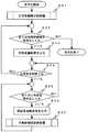
図52および図53は本発明の復号化処理手順を説明するためのフローチャートであり、図52は分割されたすべての正方形領域の復号化を行う処理手順を示すもので、図53はある1つの正方形領域における復号化手順を示すものである。
【0178】
なお、これら図52および図53のフローチャートは、先に説明した本発明の基礎となる画像処理技術における復号化処理の説明に用いた図33のフローチャートを、分割されたすべての正方形領域の復号化を行う処理手順と、ある1つの正方形領域内における復号化を行う処理手順とに分けて示すものであり、基本的な処理は図33と同じであるが、図53に示すある1つの正方形領域内を復号化する処理において、現在処理対象となっている三角形領域に対して前フレームの符号化データが選択されたか否か判定する処理と、その判定結果に対応した処理が追加されている。
【0179】
図52において、まず、すべての正方形領域を復号化したか否かを判断し(ステップS71)、すべての正方形領域の復号化が終了していれば、正方形領域合成処理を行って(ステップS72)、復号化処理を終了し、すべての正方形領域の復号化が終了していなければ、その正方形の4頂点画素値を復号し(ステップS73)、その正方形領域内の合成処理(図53参照)を行う(ステップS74)。
【0180】
図53はある1つの正方形領域の復号化処理を示すもので、まず、全階層を復号化したかを判断し(ステップS81)、全階層の復号化が終了していれば復号化処理を終了し、全階層の復号化が終了していなければ、その階層(現在処理対象となっている階層)のすべての三角形を合成したかを判断する(ステップS82)。
【0181】
そして、その階層のすべての三角形の合成が終了していなければ、その三角形領域(現在、符号化処理対象となっている三角形領域)に対し、前フレームの符号化データを選択か否かを判定し(ステップS83)、前フレームの符号化データを選択すると判定された場合は前フレームの符号化データを取得し(ステップS84)、ステップS82に戻る。また、前フレームの符号化データを選択しないと判定された場合は、現フレームの斜辺中点画素値を復号し(ステップS85)、前フレーム符号化データを更新して(ステップS86)、ステップS82に戻る。
【0182】
そして、ステップS82において、その階層(現在処理対象となっている階層)のすべての三角形を合成したかを判断し、当該階層のすべての三角形について処理を終了していれば、その階層の三角形領域合成処理を行い(ステップS87)、ステップS81に戻る。
【0183】
このように、この復号化処理では、前フレーム符号化データを選択か否か、つまり、この場合、図50で示したデータ置換を行うか否かを示す情報(“0”または“1”)を調べ、現在、復号化対象の三角形領域の上位の三角形領域でデータ置換が可能でないことを示す“0”が与えられていれば、その三角形領域については斜辺中点画素値を復号化し、かつ、前フレーム符号化データ記憶手段17に記憶されている前フレーム符号化データの更新を行う。一方、上位の三角形領域でデータ置換を行うことを示す“1”が与えられていれば、当該三角形領域以降の階層の三角形領域全体を、前フレーム符号化データを用いて復号化する。
【0184】
なお、本発明は上述の各実施形態に限られるものではなく、本発明の要旨を逸脱しない範囲で種々変形実施可能となるものである。たとえば、上述した符号化データ(図50で示す1次元化されたデータ)を所定の暗号化鍵を用いて暗号化してそれを復号化側に送信し、復号化側ではその暗号化された符号化データを所定の復号化鍵を用いて復号化するということもできる。
【0185】
たとえば、この暗号化として、2分木の各階層ごとの符号化データを階層に対応して用意された暗号化鍵を用いて暗号化する。これによって、各階層ごとのそれぞれの三角形領域のデータ(斜辺中点画素値)がその階層に用意された暗号化鍵で暗号化されたデータとして出力することができる。そして、このような符号化側からの暗号化データを復号化する際は、2分木の各階層に対応して用意された復号化鍵を取得して各階層ごとに復号するようにする。これにより、各階層対応の復号化鍵によってそれぞれの階層に応じた解像度の画像が復元されるので、たとえば、第2階層までの復号化鍵しか取得できなかった場合には、第2階層に対応した解像度での画像しか得ることができず、また、第3階層までの復号化鍵を取得すれば、第3階層までの解像度の画像を得ることができるというように、どの階層までの復号化鍵を取得したかによって、その階層に応じた解像度の画像を得ることができる。
【0186】
これによって、たとえば、画像データの閲覧システムなどにおいて、ユーザが閲覧できる階層(解像度)を制限することができ、閲覧する解像度に応じた課金の設定などを行うことができる。また、著作権の保護の目的などにも適用することができるといった効果が得られる。
【0187】
また、本発明は個々のフレーム(静止画像)に対し、省略できるデータはそれを省略するデータ省略処理を行ったあとに、前述した本発明の処理を行うようにすることもできる。
【0188】
このデータ省略処理は、ある1つのフレーム、つまり、ある1つの静止画像データにおいて、それを幾つかの正方形領域に分割し、分割されたぞれぞれの正方形領域を再帰的に三角形領域に分割して、それによって得られた三角形領域を平面近似した画素値と当該三角形領域の実際の画素値との誤差を求め、その誤差に基づいて当該三角形領域のそれ以降の分割を省略することができるか否かを判定する。そして、この判定結果に基づいて符号化すべき三角形領域の符号化データを生成する。
【0189】
さらに具体的に説明すると、再帰的に分割されたそれぞれの三角形領域を、その元となる正方形領域を根とする2分木で表現する。そして、前述したデータ省略判定処理は、処理対象の三角形領域の斜辺両端を結ぶ直線上の中点画素値を近似的な画素値とし、その近似的な画素値と当該三角形領域の実際の斜辺中点画素値との誤差の大きさが所定値未満であるか否かを判定する処理と、当該三角形領域が分割可能であるか否かを判定する処理とを含む処理をデータ省略判定処理として行い、このデータ省略判定処理を、前記処理対象の三角形領域を基点に、当該三角形領域を再帰的分割して得られる個々の三角形領域について順次行い、自身の三角形領域の誤差の大きさが所定値未満であると判定され、かつ、2分割されて生成された双方の三角形領域の誤差の大きさが所定値未満であると判定され、それが最終段の三角形領域にまで到達した場合に、当該処理対象となる三角形領域のそれ以上の分割が省略可能であることを示す情報を出力する。
【0190】
このように、個々のフレームにおいてこのようなデータ省略処理を行ったあとに本発明の動画処理を行うことによって、演算量、メモリ量をより一層削減することができる。
【0191】
また、本発明はこのようなデータ省略処理を行ったのちに、これまで説明した本発明の動画の符号化処理を行い、さらにそのあとに上述した暗号化処理することもできる。
【0192】
また、本発明は以上説明した本発明を実現するための処理手順が記述された処理プログラムを作成し、その処理プログラムをフロッピィディスク、光ディスク、ハードディスクなどの記録媒体に記録させておくこともでき、本発明は、その処理プログラムの記録された記録媒体をも含むものである。また、ネットワークから当該処理プログラムを得るようにしてもよい。
【0193】
【発明の効果】
以上説明したように本発明は、処理対象となるフレーム対応の画像をフレーム間相関を用いて符号化するものであるが、動き補償処理を行わないので、動きベクトルを求めるために多くの計算量、メモリ量を必要としていた従来技術に比べると、計算量やメモリ量を大幅に削減できる効果がある。なお、動き補償を行わないことによる符号化効率の劣化は、本発明の基礎となる画像処理技術である正方形領域を再帰的三角形領域分割することによって得られた2分木のデータ構造により、前フレームとの差異のある部分をそれに最も適したサイズの領域として表現することを可能とすることによって改善できる。つまり、従来例においては、前述したように、処理の単位が16画素×16画素のマクロブックという固定された大きさであったが、本発明においては、可能である限り、大きな領域を前フレームの符号化データで置換できるというような符号化を行う。逆に言うと、差異のある部分をできるだけ小さな領域で表現することによって、トータルとしての符号化効率を改善する効果がある。
【0194】
また、本発明の動画符号化で用いる符号化データ差分化処理は、個々のフレームデータ(静止画データ)の符号化を行ったあとのデータを用いて行われるので、これによっても、計算量やメモリ量を削減でき、さらに、本発明の基礎となる画像処理技術による符号化や、それを基にした個々のフレームのデータ省略処理とは独立して行うことができる。そのため、たとえば、本発明で用いる符号化データ差分化処理を行っている最中に、他の処理負荷が増加して、本発明の符号化データ差分化処理に割り当てられる演算処理量が少なくなった場合、その符号化データ差分化処理を中断し、それまでに処理された結果を直接に符号化出力とすることが可能である。また、他の処理負荷が始めから大きい場合には本発明の符号化データ差分化処理を全く行わないようにすることもできる。このように、システムの処理負荷の大きさに応じて、柔軟に対応することができる。
【0195】
また、符号化側からの符号化データを復号する際は、符号化側からの符号化データを解析し、その符号化データが現フレーム対する差分データであるのか、それとも、データ置換の要求されたデータであるのかを判定して、その判定結果に基づいて、三角形領域の合成を行うようにしている。このとき、データ置換の要求されたデータであるのか否かの判定は、データ置換の可能な最上位の三角形領域に付されたデータ置換が可能であることを示す情報に基づいて行い、ある三角形領域に対してデータ置換が可能であることを示す情報が与えられている場合には、当該三角形領域より下の階層の三角形領域全体を、そのデータ置換が可能であることを示す情報の付加された三角形領域の符号化データを用いて復号化するようにしているので、効率的な三角形領域の合成が行える。
【図面の簡単な説明】
【図1】 本発明の基礎となる画像処理技術についての符号化側の構成図である。
【図2】 図1で示した画像データ入力手段の構成を説明する図である。
【図3】 処理対象画像が正方形である場合、その画像を三角形に分割した例を示す図である。
【図4】 処理対象画像が正方形でない場合、その画像を複数の正方形領域に分割した例を示す図である。
【図5】 画像を複数の正方形領域に分割する際の分割処理手順を説明するフローチャートである。
【図6】 画像を複数の正方形領域に分割する際に生じる空白部分へ画素値0を補填する例を説明する図である。
【図7】 ある1つの正方形を2つの三角形に分割する2つの方法(第1の方法と第2の方法)について説明する図である。
【図8】 ある1つの正方形を2分割して2つの三角形を得て、さらに、その2つの三角形を再帰的に分割して得られた三角形の8種類の型を示す図である。
【図9】 図8で示した三角形の型が相互に関連つけられることを説明する図である。
【図10】 図7で示した2つの分割方法によって分割された三角形と元の正方形との画素値の継承規則を示す図である。
【図11】 図8で示した8種類の型をそれぞれ2分割して得られた三角形の型とその画素値の継承規則を示す図である。
【図12】 ある1つの正方形を第1の方法で2分割して得られた2つの三角形をさらに2分割して得られる三角形の型を示す図である。
【図13】 ある1つの正方形を第1の方法で2分割して得られた2つの三角形をさらに2分割し、それをさらに2分割して得られる三角形の型を2分木で表現した図である。
【図14】 図1で示した符号側の具体的な処理を説明するために一辺の画素数が3で、それぞれの画素に具体的な数値(画素値)を与えた図である。
【図15】 図14を用いて三角形領域の再帰的分割処理を行う例を説明する図である。
【図16】 図15で示した三角形領域の再帰的分割処理手順を説明するフローチャートである。
【図17】 図15で示した三角形領域の再帰的分割処理手順を行う際の求めるべき画素値を図11に示す継承規則を参照して得る処理を説明する図である。
【図18】 図15から図17で示した処理を2分木で表現した図であり、図13の2分木表現に斜辺中点の画素値を加えた図である。
【図19】 処理対象画像を複数の正方形領域に分割した例を示す図である。
【図20】 図19で得られた正方形領域それぞれを2分木で表現した例を説明する図である。
【図21】 ある1つの2分木で表現される画像データを符号化する順序の一例を説明する図である。
【図22】 図21で説明した符号化手順によって符号化されたデータ例を示す図である。
【図23】 ある1つの2分木で表現される画像データを符号化する順序の他の例を説明する図である。
【図24】 図23で説明した符号化手順によって符号化されたデータ例を示す図である。
【図25】 本発明の基礎となる画像処理技術についての符号化処理手順を説明するフローチャートである。
【図26】 本発明の基礎となる画像処理技術についての復号化側の構成図である。
【図27】 図22の符号化データを復号化する手順を説明する図である。
【図28】 図27の復号化手順を実際の画像の復元を例にとって説明する図である。
【図29】 画像データを復号化する際の三角形内部にデータを補間する処理の一例を説明する図である。
【図30】 画像データを復号化する際、ある特定の領域(たとえば関心領域)を優先的に高解像度で複合する処理を説明する図である。
【図31】 図30におけるある特定の領域を処理対象となる画像に対応させた例を示す図である。
【図32】 図30による復号化手順によって復元される画像の復元度合い変化を示す図である。
【図33】 本発明の基礎となる画像処理技術についての復号化処理手順を説明するフローチャートである。
【図34】 図26で示した画像データ出力手段の構成を説明する図である。
【図35】 本発明の画像処理装置の符号化側の実施形態を説明する構成図である。
【図36】 本発明の符号化側の処理手順を説明するフローチャートであり、正方形領域分割とその符号化手順を説明するフローチャートである。
【図37】 本発明の符号化側の処理手順を説明するフローチャートであり、分割されたある1つの正方形領域内の符号化手順を説明するフローチャートである。
【図38】 本発明の実施形態の具体例を説明するための2分木の例を示す図である。
【図39】 図38に示す2分木に対応する再帰的三角形領域分割例を示す図である。
【図40】 図39の2分木で表現される画像データを符号化する順序を説明する図である。
【図41】 図40に示す順序で符号化されたデータを縦方向に並べたデータ配列を示す図である。
【図42】 本発明の実施形態で用いる画像例であり、(a)は前フレームデータ、(b)は現フレームデータを示す図である。
【図43】 図42の画像例を再帰的三角形領域分割した図である。
【図44】 前フレーム符号化データと現フレーム符号化データとの差分に基づいて個々の三角形領域がデータ置換可能か否かを判定する例を説明する図であり、最終階層の三角形領域における処理例を説明する図である。
【図45】 前フレーム符号化データと現フレーム符号化データとの差分に基づいて個々の三角形領域がデータ置換可能か否かを判定する例を説明する図であり、第3階層の三角形領域における処理例を説明する図である。
【図46】 前フレーム符号化データと現フレーム符号化データとの差分に基づいて個々の三角形領域がデータ置換可能か否かを判定する例を説明する図であり、第2階層の三角形領域における処理例を説明する図である。
【図47】 前フレーム符号化データと現フレーム符号化データとの差分に基づいて個々の三角形領域がデータ置換可能か否かを判定する例を説明する図であり、第1階層の三角形領域における処理例を説明する図である。
【図48】 図38の2分木において図44から図47の処理を行った結果の2分木を示す図である。
【図49】 図48に示す2分木において符号化データ出力例を説明する図である。
【図50】 図49による符号化データを縦に並べたデータ配列を示す図である。
【図51】 本発明の画像処理装置の復号化側の実施形態を説明する構成図である。
【図52】 本発明の復号化側の処理手順を説明するフローチャートであり、それぞれの正方形領域の復号化と正方形領域の合成処理手順を説明するフローチャートである。
【図53】 本発明の復号化側の処理手順を説明するフローチャートであり、分割されたある1つの正方形領域内の復号化手順を説明するフローチャートである。
【図54】 従来の動画符号化の一例としてのH.261の構成を示す図である。
【符号の説明】
1 画像データ入力手段
2 正方形領域分割手段
3 再帰的三角形領域分割手段
4 三角形領域分割制御手段
5 符号化データ生成手段
6 符号化データ出力手段
7 符号化データ記憶手段
8 前フレーム符号化データ記憶手段
9 符号化データ比較手段
10 符号化データ選択手段
11 符号化データ入力手段
12 符号化データ解析手段
13 再帰的三角形領域合成手段
14 三角形領域合成制御手段
15 正方形領域合成手段
16 画像データ出力手段
17 前フレーム符号化データ記憶手段
18 符号化データ選択手段
20 符号化データ差分化手段
30 符号化データ選択判定手段
31 形状型記憶手段
32 頂点画素値記憶手段
33 斜辺中点画素値取得手段
34 形状型更新手段
35 頂点画素値更新手段
#1〜#8 三角形型[0001]
BACKGROUND OF THE INVENTION
The present invention relates to an image processing method, an image processing apparatus, and an image processing program. In particular, an image processing method and an image for encoding a moving image data using an image processing technique in which the image is a square region, the square region is divided into triangular regions, and image processing is performed on the divided triangular regions, and the moving image data is decoded. The present invention relates to a processing apparatus and an image processing program.
[0002]
[Prior art]
The need for video coding technology that compresses and decompresses video signals with high efficiency is increasing along with the widespread use of mobile phones and the Internet, and the demand for multimedia communication on them.
[0003]
In this video encoding technology, in order to enable processing on a small portable device, encoding efficiency is high so that a low bit rate can be realized, and the amount of calculation and memory during the processing are small. Is required. Furthermore, when the encoding process is executed on a general-purpose device instead of a dedicated machine, it is required that it is possible to flexibly cope with load fluctuations of other processes processed in parallel on the device.
[0004]
As a method of encoding a moving image, there is a method of encoding data of each frame as independent still image data for each frame. An example of this is motion JPEG. This method is characterized in that, since each encoded frame is independent, it is easy to edit, fast forward, and rewind.
[0005]
In addition, many devices capable of image input often have hardware for still image processing, which is advantageous in that it can be used. However, it cannot be said that the encoding efficiency as a moving image is high.
[0006]
As an encoding method for improving the encoding efficiency of moving images, there is a method of encoding only the difference from the previous frame data. This utilizes the fact that the correlation of data between frames is large in moving image data. Furthermore, this method can be divided into a case of obtaining a difference between the previous frame data and the current frame data in consideration of the movement of the object and a case of obtaining the difference without considering the movement.
[0007]
The difference considering the motion of the object is also called motion compensation processing, and considers whether data in a certain range of the previous frame is at a different position in the current frame. For example, a part of the previous frame data is moving in a certain direction on the current frame data is a situation that frequently appears in moving images. In such a case, in the motion compensation process, information called a motion vector indicating which region of the previous frame data has moved in which direction and how much is encoded. This is characterized in that the amount of data to be encoded can be reduced compared to a difference that does not take motion into account. Specific examples of this are as follows. There is encoding such as H.261.
[0008]
On the other hand, the difference that does not take into account the movement of the object simply means how much difference exists in the data at the corresponding position between the previous frame data and the current frame data. The area where the difference is small is processed by using the previous frame data as it is, and only the information that the previous frame data is used is encoded. This process can also be considered as a special case where the motion vector is 0 in the motion compensation process. In this sense, the process including motion compensation is more general, but this assumption has a feature that the process can be made very light.
[0009]
Each of the encoding methods described above is assumed to encode a real-time moving image. However, in the accumulated moving image encoding, the frame data to be referred to is not only the previous frame data, but a plurality of past frames. There is also a method for obtaining a difference between frame data and a plurality of future frame data. Specific examples include moving picture coding in MPEG.
[0010]
Here, a conventional general encoding method will be described. FIG. 261 is a diagram illustrating an encoding method of H.261, schematically, image data input means 201, motion compensation means 202, data selection means 203, DCT (discrete cosine transform) means 204, quantization means 205, and inverse quantization It has a configuration including
[0011]
In such a configuration, image data for one frame input to the image
[0012]
The
[0013]
The data selected by the
[0014]
The data obtained by dequantizing the quantized data by the inverse quantization means 206 and dequantizing by the inverse DCT means 207 is stored in the data storage means 208, and the data of the next frame Used as the previous frame data for the differentiation process. This corresponds to the fact that the previous frame data that can be referred to on the decoding processing side is only data decoded from the encoded data.
[0015]
Here, the motion compensation process is not performed in an area of an arbitrary size, but is performed in units of a square area of 16 pixels × 16 pixels called a macroblock. In addition, since the conversion processing to spatial frequency such as DCT processing disperses information on the position, the motion compensation processing is executed before the DCT processing, quantization processing, etc. are performed on the input image. There is a need.
[0016]
In this encoding process, a DCT process or the like is a process that requires a large amount of calculation, but a motion compensation process is also a process that requires a large amount of calculation. In other words, the process for obtaining the motion vector is performed for each block.
[0017]
[Expression 1]
In this process, i and j are calculated such that the error Err (i, j) given by is minimized and is smaller than a predetermined value.
[0019]
In the above equation (1), it is assumed that a square error is used as an evaluation criterion, and D (x, y) represents a data (pixel) value at a certain coordinate (x, y). Similarly, the data (pixel) value of the previous frame in P (x + i, y + j) is shown. Here, the value (i, j) represents a motion vector. L represents the size of the square block to be processed. As a result of this arithmetic processing, a difference Err (i, j) with respect to a certain motion vector (i, j) is obtained.
[0020]
H. In the H.261 encoding method, L = 16. As a set of i and j, the calculation is performed in the range of −15 to +15. Therefore, if it is simply executed, it is necessary to perform the expression (1) 900 times or more.
[0021]
Further, since this motion compensation process is a process using a square area called a macroblock, even if there is a motion in a small part of the process, the entire block must be processed. In addition, when copying a block in motion compensation, there is a possibility that discontinuity occurs at the boundary of the block.
[0022]
As examples of techniques for improving the amount of computation and discontinuity, techniques described in Japanese Patent Application Laid-Open No. 8-37664, “Video Encoding / Decoding Device”, and Japanese Patent Application Laid-Open No. 10-341441. There is a technology such as “a motion estimation method of a moving image using a two-dimensional triangular patch line lattice model”.
[0023]
The technique described in Japanese Patent Application Laid-Open No. 8-37664 is obtained by obtaining representative points from input data, setting a triangular area connecting them, as shown in FIG. The motion vector between frames is obtained. The representative points and the triangular area connecting them can be taken at an arbitrary position and an arbitrary size depending on the target data. As a result, the amount of motion compensation calculation can be reduced, and smoother motion and deformation from the previous frame can be achieved.
[0024]
On the other hand, the technique described in Japanese Patent Laid-Open No. 10-341441 is different from the technique described in Japanese Patent Laid-Open No. 8-37664 described above, and as shown in FIG. On the other hand, a lattice made up of small two-dimensional triangles called a two-dimensional triangular patch line lattice model obtained by dividing a macroblock into two diagonal lines is applied. Thereafter, as shown in FIG. 2 described in the publication, a motion vector is calculated with reference to the vertex of the triangular area. Then, based on the obtained motion vector, the triangular patch line lattice is deformed as shown in FIG. 5C described in the publication. As a result, finally, as in the technique described in JP-A-8-37664, the amount of calculation can be reduced, and smoother movement and deformation from the previous frame can be achieved.
[0025]
[Patent Document 1]
JP-A-8-37664
[Patent Document 2]
JP-A-10-341441
[0026]
[Problems to be solved by the invention]
However, in the technique described in Japanese Patent Application Laid-Open No. 8-37664, a large amount of calculation is required for obtaining the representative point itself, and if the representative point is erroneously detected, the image quality is greatly deteriorated. There is a problem. Also in Japanese Patent Application Laid-Open No. 10-341441, a large amount of calculation is required to obtain a motion vector.
[0027]
The motion compensation process greatly improves the compression efficiency of moving images. However, although there are various improvement measures, the motion compensation processing still requires a very large amount of calculation and memory, for example, a situation in which hardware capability and power supply capability such as portable information equipment are severely restricted. The use below is often difficult. In addition, although dedicated hardware improves these problems, new problems arise in terms of versatility and cost.
[0028]
In addition, when the video encoding process is performed in parallel with other processes on a general-purpose device, the calculation capacity allocated to the video encoding process can be flexibly changed depending on the load fluctuation of the other processes. Is more convenient.
[0029]
However, when the motion compensation process exists in the forefront of the process as in the conventional example (see FIG. 54), the motion compensation process is integrated with the encoding process, and it is difficult to cope with load fluctuations. . In addition, the fact that the motion compensation process exists in the forefront of the process means that the obtained encoded data amount is not the target encoded data amount, and when performing a retry, it goes back to the motion compensation process and many Since it is necessary to redo processing, there is a problem that the amount of calculation at the time of retry increases.
[0030]
Accordingly, an object of the present invention is to provide an image processing method, an image processing apparatus, and an image processing program that can realize encoding and decoding of a moving image with a small amount of calculation and a small amount of memory.
[0031]
[Means for Solving the Problems]
The present invention encodes and decodes moving image data. However, when encoding and decoding the moving image data, it is assumed that an image to be processed is a square. When the image is squared, a method of dividing the processing target image into one or more square regions, and another method of generating one square region by transforming the processing target image into a square can be considered. In the present invention, the former, that is, a method of dividing the processing target image into one or more square areas is adopted.
[0032]
First, regarding the image processing method of the present invention, the encoding side of this image processing method is an image processing method that encodes image data corresponding to continuous individual frames constituting a moving image using inter-frame correlation. As the image processing procedure, an image input step for inputting image data corresponding to a frame, a square region dividing step for dividing the input image data for a frame into one or more square regions, A recursive triangular region dividing step for recursively dividing each square region into triangular regions, an encoded data generating step for encoding the divided triangular regions, and individual data generated by the encoded data generating step. Use interframe correlation for encoded data corresponding to the frame, and change the encoded data for the current frame to the encoded data of the previous frame. If it is determined whether or not it can be replaced with the encoded data of the previous frame, the encoded data difference step that outputs information indicating that, and the determination result of this encoded data difference step And an encoded data output step for outputting encoded data based on the above.
[0033]
In such an image processing method, the coded data difference step uses the coded data corresponding to each individual frame as the current frame coded data, and converts the current frame coded data and the previous frame coded data into the respective encoded data. The corresponding triangle areas are compared, and it is determined whether or not the magnitude of the difference is less than a predetermined value. If the difference is less than the predetermined value, the current frame encoded data in the triangle area is converted to the previous frame code. If the difference is greater than or equal to a predetermined value, the triangle area outputs the encoded data of the current frame.
[0034]
Further, in this image processing method, each of the recursively divided triangular regions is represented by a binary tree having a square region as a root as a root, and the encoded data differentiation step includes the previous frame. Find the difference between the triangular area of the final hierarchy of the binary tree corresponding to the encoded data and the triangular area of the final hierarchy of the binary tree corresponding to the current frame encoded data, and based on the magnitude of the difference It is determined whether or not the triangular area can be replaced with the encoded data of the same area in the previous frame. In the triangular area in a higher hierarchy, the two triangular areas obtained by dividing itself into two are both When it can be replaced with encoded data in the same area of the frame, it is determined that its own triangular area can also be replaced with encoded data in the same area of the previous frame.
[0035]
Further, in this image processing method, the information indicating the replacement with the previous frame encoded data is attached only to the uppermost triangular area to be replaced with the previous frame encoded data.
[0036]
Also, the decoding side of the image processing method of the present invention divides image data corresponding to continuous individual frames constituting a moving image into one or more square areas, and each square area is recursively divided into triangular areas. After the processing, the divided triangular region is encoded, and the image data corresponding to the frame to be processed is encoded using the inter-frame correlation, and the encoded data is decoded. An image processing procedure includes an encoded data input step for inputting encoded data, an encoded data analysis step for analyzing the encoded data input to the encoded data input step, and the code A code for determining whether to select the previous frame encoded data or the current frame encoded data based on the analysis result of the encoded data analysis step. Based on the determination result of the encoded data selection determination step, the recursive triangle region combining step for recursively combining the triangle regions based on the determination result of the encoded data selection determination step, and the square region for combining the square regions with the combined triangle regions The image processing apparatus includes a combining step and an image data output step for restoring and outputting the image data from the combined square area.
[0037]
In such an image processing method, the determination whether to select the previous frame encoded data or the current frame encoded data performed in the encoded data selection determination step is information indicating that the previous frame data is to be replaced. If the information indicating that a certain triangular area is to be replaced with the previous frame data is given, the entire triangular area below the triangular area is converted to the encoded data of the same area in the previous frame. It is used for decoding.
[0038]
Further, the encoding side of the image processing apparatus of the present invention is an image processing apparatus that encodes image data corresponding to continuous individual frames constituting a moving image by using inter-frame correlation. Image input means for inputting data, square area dividing means for dividing input image data into one or more square areas, and recursion for recursively dividing each divided square area into triangular areas Using the inter-frame correlation for the encoded data corresponding to each frame generated by the encoded data generation means, and the encoded data generation means for encoding the divided triangle areas. It is determined whether or not the encoded data for the frame can be replaced with the encoded data for the previous frame. Encoded data differentiating means for outputting information indicating is characterized by including the encoded data output means for outputting the encoded data based on the determination result of the coded data difference means.
[0039]
In such an image processing apparatus, the encoded data differentiating means uses the encoded data corresponding to each frame as the current frame encoded data, and the current frame encoded data and the previous frame encoded data are respectively The corresponding triangle areas are compared, and it is determined whether or not the magnitude of the difference is less than a predetermined value. If the difference is less than the predetermined value, the current frame encoded data in the triangle area is converted to the previous frame code. If the difference is greater than or equal to a predetermined value, the triangle area outputs the encoded data of the current frame.
[0040]
Further, in this image processing apparatus, each of the recursively divided triangular regions is represented by a binary tree having a root of the square region as the root, and the encoded data differentiating means includes a previous frame code The difference between the triangular area of the final hierarchy of the binary tree corresponding to the encoded data and the triangular area of the final hierarchy of the binary tree corresponding to the current frame encoded data is obtained, and the triangle is determined based on the magnitude of the difference It is determined whether or not the area can be replaced with the encoded data of the same area of the previous frame. In the triangular area of the higher hierarchy, the two triangular areas obtained by dividing itself into two are both the previous frame. If it can be replaced with encoded data in the same area, it is determined that its own triangular area can also be replaced with encoded data in the same area of the previous frame.
[0041]
In this image processing apparatus, the information indicating that replacement is performed with the previous frame encoded data is attached only to the uppermost triangular area that is to be replaced with the previous frame encoded data.
[0042]
Also, the decoding side of the image processing apparatus of the present invention divides image data corresponding to continuous individual frames constituting a moving image into one or more square areas, and each square area is subjected to recursive triangle area division processing. After that, the divided triangular area is encoded, and the image data corresponding to the frame to be processed is encoded using the inter-frame correlation, and the encoded image data is decoded. An encoded data input unit for inputting encoded data, an encoded data analyzing unit for analyzing the encoded data input to the encoded data input unit, and the encoded data Encoded data selection determining means for determining whether to select previous frame encoded data or current frame encoded data based on the analysis result by the analyzing means Based on the determination result of the encoded data selection determining means, the recursive triangle area combining means for recursively combining the triangle areas and the square area combining means for combining the square areas with the combined triangle areas are combined. And image data output means for restoring and outputting the image data from the square area.
[0043]
In such an image processing apparatus, the determination of whether to select the previous frame encoded data or the current frame encoded data performed by the encoded data selection determination means indicates that the previous frame encoded data is replaced. If information indicating that a certain triangular area is to be replaced with the previous frame encoded data is given, the entire triangular area below the triangular area is assigned to the same area of the previous frame. Decoding is performed using the encoded data.
[0044]
Further, the encoding side of the image processing program of the present invention is an image processing method for encoding image data corresponding to continuous individual frames constituting a moving image using inter-frame correlation, and as an image processing procedure thereof, An image input step for inputting image data corresponding to a frame, a square region dividing step for dividing the input image data corresponding to a frame into one or more square regions, and recursively dividing each divided square region A recursive triangular region dividing step for dividing the divided triangular region into an encoded data generation step for encoding the divided triangular region, and encoded data corresponding to individual frames generated by the encoded data generating step. Use inter-frame correlation to determine whether the encoded data for the current frame can be replaced with the encoded data of the previous frame, When it is determined that the encoded data of the frame can be replaced, an encoded data difference step that outputs information indicating the frame, and a code that outputs encoded data based on the determination result of the encoded data difference step And a data output step.
[0045]
In such an image processing program, the coded data differentiation step uses the coded data corresponding to each frame as the current frame coded data, and the current frame coded data and the previous frame coded data are respectively The corresponding triangle areas are compared, and it is determined whether or not the magnitude of the difference is less than a predetermined value. If the difference is less than the predetermined value, the current frame encoded data in the triangle area is converted to the previous frame code. If the difference is greater than or equal to a predetermined value, the triangle area outputs the encoded data of the current frame.
[0046]
In this image processing program, each of the recursively divided triangular regions is represented by a binary tree having a root of the original square region, and the encoded data differentiation step includes the previous frame. Find the difference between the triangular area of the final hierarchy of the binary tree corresponding to the encoded data and the triangular area of the final hierarchy of the binary tree corresponding to the current frame encoded data, and based on the magnitude of the difference It is determined whether or not the triangular area can be replaced with the encoded data of the same area in the previous frame. In the triangular area in a higher hierarchy, the two triangular areas obtained by dividing itself into two are both When it can be replaced with encoded data in the same area of the frame, it is determined that its own triangular area can also be replaced with encoded data in the same area of the previous frame.
[0047]
Further, in this image processing program, information indicating that the previous frame encoded data is to be replaced is attached only to the uppermost triangular area to be replaced with the previous frame encoded data.
[0048]
Further, the decoding side of the image processing program of the present invention divides image data corresponding to continuous individual frames constituting a moving image into one or more square areas, and each square area is recursively divided into triangular areas. After the processing, the divided triangular region is encoded, and the image data corresponding to the frame to be processed is encoded using the inter-frame correlation, and the encoded data is decoded. An image processing procedure includes an encoded data input step for inputting encoded data, an encoded data analysis step for analyzing the encoded data input to the encoded data input step, and the code Determine whether to select previous frame encoded data or current frame encoded data based on the analysis result of the encoded data analysis step An encoded data selection determining step, a recursive triangle area combining step for recursively combining triangular areas based on the determination result of the encoded data selection determining step, and a combined square area by combining the triangular areas The method includes a square area synthesis step and an image data output step for restoring and outputting image data from the synthesized square area.
[0049]
In such an image processing program, the determination whether to select the previous frame encoded data or the current frame encoded data performed in the encoded data selection determination step is information indicating that the previous frame data is to be replaced. If the information indicating that a certain triangular area is to be replaced with the previous frame data is given, the entire triangular area below the triangular area is converted to the encoded data of the same area in the previous frame. It is used for decoding.
[0050]
As described above, the present invention performs processing after making an image into a square area, and when encoding the image data to be processed, the encoding side converts the image data to be processed into one or more image data. Dividing into square areas, recursively dividing the extracted squares into triangle areas, and obtaining pixel information of the three vertices of each triangle area (hereinafter referred to as pixel values) and the pixel value of the hypotenuse midpoint I have to. At this time, the shape of each triangle obtained by the recursive division process can be automatically determined according to the division order if the method of dividing the original square is determined. Further, the pixel value at the apex of each triangle can inherit the pixel value of the square as it is, and the pixel value at the midpoint of the hypotenuse can also be obtained from the original square. The triangle type and the pixel value to be held (the hypotenuse midpoint pixel value) can be represented by a binary tree, and the encoded data is one-dimensionalized based on the binary tree. Can be output as
[0051]
According to this, when encoding image data to be processed, only a small amount of data is to be held or transmitted when encoding is performed, which can greatly simplify the calculation and memory. The usage of can be greatly reduced.
[0052]
In the present invention, this image processing technique is used to encode and decode a moving image, and the moving image encoding uses an inter-frame correlation for a frame-corresponding image to be processed. Is encoded without performing. As described above, since the present invention does not use motion compensation processing, the calculation amount and the memory amount can be greatly reduced as compared with the conventional technique that requires a large amount of calculation amount and memory amount to obtain the motion vector. is there.
[0053]
In addition, since the difference between frames is calculated using only the encoded data, the amount of calculation and the amount of memory can also be reduced. Note that the deterioration in coding efficiency due to the absence of motion compensation differs depending on the data structure of the binary tree obtained by recursively dividing the square area, which is the image processing technique underlying the present invention. This can be improved by making it possible to express a certain part as a region of the most suitable size.
[0054]
That is, in the conventional example, as described above, the processing unit has a fixed size of a macro book of 16 pixels × 16 pixels. However, in the present invention, a large area is set to the previous frame as much as possible. Encoding that can be replaced with the encoded data is performed. In other words, expressing the difference portion in as small an area as possible has the effect of improving the overall coding efficiency.
[0055]
In addition, as described above, the code data differentiating process used in the moving image encoding of the present invention is performed using the encoded data, so that the encoding by the image processing technology that forms the basis of the present invention, It can be performed independently of the data omission processing of individual frames based on it. Therefore, for example, while the code data differentiating process used in the present invention is being performed, another processing load increases, and the amount of calculation processing allocated to the code data differentiating process used in the present invention decreases. In such a case, it is possible to interrupt the encoded data difference process and directly output the processed result as an encoded output. In addition, when the other processing load is large from the beginning, the encoded data differentiation process of the present invention can be prevented from being performed at all. Thus, it can respond flexibly according to the size of the processing load of the system. In addition to the above-described various effects, performing encoded data difference processing using encoded data may cause the finally obtained encoded data to differ from the target data. In this case, it is possible to reduce the amount of calculation when performing the retry process.
[0056]
In other words, in the conventional technique, after performing motion compensation on the input image data, the method of encoding and outputting the encoded data, when retrying, goes back to the motion compensation process, and again However, it is necessary to redo multiple stages of processing, such as encoding after motion compensation processing, but in the present invention, it is only necessary to redo the encoded data difference processing, so the amount of computation when retrying is performed. Can be reduced.
[0057]
Also, when decoding the encoded data from the encoding side, the encoded data from the encoding side is analyzed, and whether the encoded data is differential data for the current frame, or data replacement is requested It is determined whether the data is data, and the triangular regions are synthesized based on the determination result. At this time, whether or not the data is requested to be replaced is determined based on information indicating that data replacement is possible for the uppermost triangular area where data replacement is possible. When information indicating that data replacement is possible is given to an area, information indicating that the data replacement is possible is added to the entire triangular area below the triangle area. Since the decoding is performed using the encoded data of the triangular area, the triangular area can be efficiently synthesized.
[0058]
DETAILED DESCRIPTION OF THE INVENTION
Hereinafter, embodiments of the present invention will be described with reference to the drawings. First, as a technique underlying the present invention, an image to be processed is divided into one or more square areas, each square area is recursively divided into triangle areas, and the divided triangle areas are encoded. The image processing to be performed and the image processing to decode the encoded data encoded thereby will be described, and then the moving image encoding processing of the present invention and the decoding processing to decode it will be described.
[0059]
FIG. 1 shows the encoding of an image processing apparatus according to the present invention, that is, an image to be processed is divided into one or more square areas, and each square area is recursively divided into triangular areas. It is a block diagram which shows the structure of the encoding side which encodes a triangular area | region. The configuration is roughly divided into image data input means 1, square area division means 2, recursive triangle area division means 3, triangle area division control means 4, encoded data generation means 5, and encoded data output means 6. It has a configuration.
[0060]
As shown in FIG. 2, the image data input means 1 is separated into a pixel data input means 101 for inputting individual pixel data and a color component separation means 102 for separating the input pixel color data into each color component. Based on the color data, for example, it has a color conversion means 103 for converting RGB to YUV data, and a data thinning means 104 for thinning data if necessary. The image data input to the image data input means 1 may be image data from a camera, image data from a file, image data from some communication means, and the like.
[0061]
The recursive triangle
[0062]
The operation of each component shown in FIG. 1 will be described in detail below.
[0063]
In the present invention, the image data to be processed is a square, and is recursively divided into triangular areas, and image processing is performed on the triangular areas. For example, assume that one color component of image data obtained from the image data input means 1 is as shown in FIG. The present invention expresses this as a set of triangular regions as shown in FIG.
[0064]
Thus, in the present invention, processing is performed on the assumption that the image data to be processed is a square, but the image data obtained from the image data input means 1 is not necessarily a square. Therefore, processing when image data is not square will be described.
[0065]
When the input image data is not square, the image data input by the square area dividing means 2 is divided into one or more square areas. For example, when the input image data is a horizontally long rectangular image as shown in FIG. 4A, it is divided into a plurality of square areas as shown in FIG. At this time, if the number of pixels included in one side of the divided square is L, it is desirable that L is an N remainder of 2 + 1. The reason for this will be described later. N is a natural number.
[0066]
As described above, when an image that is not originally square is divided into square areas by the square
[0067]
FIG. 5 is a flowchart for explaining the square area division processing procedure performed by the square area division processing means 2. First, L is input as one side value of the square area to be divided (step S1). However, as described above, L is an N remainder of 2 + 1 (N is a natural number). Here, when the width W of the image is not an integer multiple of L, 0 is inserted until the width of the image becomes an integer multiple of L (step S2). Similarly, when the height H of the image is not an integral multiple of L, 0 is inserted until the height H of the image is an integral multiple of L (step S3).
[0068]
FIG. 6 shows an example in which the square area division processing described in FIG. 5 is performed on a certain horizontally long image. As can be seen from FIG. 6, since the width W of the image is not an integral multiple of L, it is assumed that the width of the image is an integral multiple of L, and 0 is filled in the margin. Similarly, since the height H of the image is not an integral multiple of L, it is assumed that the height H of the image is an integral multiple of L, and 0 is filled in the margin.
[0069]
In the example described with reference to FIGS. 5 and 6, the width direction and the height direction of the image are set to integer multiples of L, and the resulting blank portion is filled with 0, but other than that, For example, as seen in processing such as JPEG, the pixel values in the rightmost column in the image are repeated in the width direction, and the pixel values in the lowermost row in the image are repeated in the height direction. It may be something like repeating. Further, as seen in JPEG2000, the image value is folded at the rightmost column in the image in the width direction, and the image value is folded at the lowermost row in the image in the height direction. It may be something like this.
[0070]
Since the subsequent processing is independent processing in each of the divided square areas as in JPEG, the description will be continued assuming that the image data is square without impairing generality.
[0071]
Next, the process of dividing each square divided into square areas as described above into triangles will be described. The process of dividing into triangles is performed by the recursive triangle area dividing means 3. The recursive triangular area dividing means 3 recursively divides each square area into triangular areas. For example, as shown in FIGS. Divided into two triangles. Although not shown in FIGS. 7A and 7B, the divided triangles are further divided into triangles.
[0072]
There are two ways to divide the square into triangles. The first method is as shown in FIG. 7 (a), and the second method is as shown in FIG. 7 (b). It is how.
[0073]
That is, when the pixel values at the four corners of the square are a, b, c, and d, FIG. 7A is divided into two triangles by the first method, and FIG. This is an example of dividing into two triangles by the method, and the types of triangles generated by being divided by using the first and second methods are represented by # 1, #, as shown in the respective drawings. It will be expressed as 2, # 3, # 4.
[0074]
Incidentally, there are a total of eight types of triangles obtained by recursively dividing the triangles divided as shown in FIGS. 7A and 7B, and each of the eight types is shown in FIG. 1, # 2, # 3, # 4, # 5, # 6, # 7, and # 8 are assigned model numbers. Note that a, b, and c attached to the respective vertices of each triangle shown in FIG. 8 represent pixel values at the respective positions, and d attached to the respective hypotenuses is in the hypotenuse. This represents the pixel value at the point position, which will be described later.
[0075]
Each triangle type (triangle type) divided into such recursive triangle regions can be associated with each other. For example, as shown in FIG. 9, when a triangle of
[0076]
By the way, the method of dividing the square into triangles (first method and second method) has been described with reference to FIG. 7 described above. At this time, how the pixel values at the positions of the four vertices of the square are converted into triangles. Explain whether it is inherited.
[0077]
Here, if the pixel values of the four vertices of the square are a, b, c, and d, the inheritance patterns of the pixel values a, b, c, and d of the four vertices of the square are shown in FIGS. There are two types according to the division method described in b).
[0078]
FIG. 10 shows this inheritance rule. For example, if the square is divided into triangles by the method (first method) as shown in FIG. 7A, the type before the division (square) is represented here as # 0 as shown in the upper part of FIG. Assuming that the pixel values (a, b, c, d) of the four vertices of the square are inherited as (a, b, c,-) as the pixel values of the # 1 type triangle obtained in the triangulation. , (B, c, d,-) is inherited as the pixel value of the # 2 type triangle.
[0079]
On the other hand, if the square is triangulated by the method (second method) as shown in FIG. 7B, the shape before the division (square) is again expressed as # 0 as shown in the lower part of FIG. Then, the pixel values (a, b, c, d) at the four vertices of the square are inherited as (a, c, d,) as the # 3 type triangular pixel values obtained in the triangulation. (A, b, d,-) is inherited as the pixel value of the
[0080]
In the present invention, in addition to the pixel values of the three vertices of each triangle, four pixel values including the pixel information of the midpoint of the hypotenuse of the triangle are considered. In FIG. The portion shown is the pixel value of the hypotenuse midpoint, and this hyphen indicates that it is unknown or that the pixel value needs to be set.
[0081]
FIG. 11 shows the inheritance rules of the pixel values when the eight types of triangles shown in FIG. 8 are further divided. As shown in FIG. 11, the types before the division (# 1 to # 8) When the triangle is divided into two types of triangles, the pixel values at that time are inherited as shown in FIG. In FIG. 11 as well, the portion indicated by a hyphen “-” is the pixel value of the hypotenuse midpoint, and this hyphen indicates that it is unknown or that the pixel value needs to be set. ing.
[0082]
According to FIG. 11, for example, when a # 6 type triangle whose vertex pixel values are a, b and c and whose hypotenuse midpoint pixel value is d is divided, two triangles of # 1 type and # 4 type are divided. The pixel values of the # 1 type triangle are (a, d, c, −), and the pixel value of the # 4 type triangle is (c, d, b, −).
[0083]
A summary of the above recursive triangulation process will be described with reference to FIG. A certain square is divided into triangles of
[0084]
The recursive triangulation process described above can be expressed by a binary tree as shown in FIG. In FIG. 13, the numbers in the circles indicate triangle shapes. A binary tree having a circle without a number in the uppermost portion as a square and this as a root R is generated.
[0085]
The triangles of the two nodes (nodes) N11 and N12 generated from the route R correspond to the two division methods (first method or second method) in FIGS. 7A and 7B. However, once this is determined, the triangle formed by dividing each node into two is uniquely determined by the inheritance rule as shown in FIG. For example, as shown in FIG. 11, a
[0086]
Hereinafter, for the sake of simplification of description, a triangle having a triangle type T, pixel values at the vertices a, b, and c, and a pixel value at the midpoint of the hypotenuse is denoted by T (a, b, c, d). For example, a triangle whose triangle type is # 6, the pixel values of its three vertices are a, b, and c, and the pixel value of the hypotenuse midpoint is d is represented by # 6 (a, b, c, d). It is expressed as being divided into # 1 (d, b, c,-) and # 4 (a, d, c,-).
[0087]
As is clear from this example, the triangle region division is performed using the inheritance rule of FIG. 11 by supplementing the pixel value of the midpoint of the hypotenuse that is indefinite indicated by a hyphen in the triangle after dividing each triangle. Can be done recursively.
[0088]
This is because, in order to express one triangle, like the technique described in Japanese Patent Laid-Open No. 9-191409 cited in the above-mentioned prior art section, three X coordinate values of three vertices, Compared to the case where three pixel values of three and three vertices are required, and a total of nine pieces of pixel information are necessary and held, the data amount is 1/9 in the worst case.
[0089]
As described above, the recursive triangle area dividing means 3 shown in FIG. 1 includes at least the shape type storage means 31 for storing eight types of triangles from # 1
[0090]
The above recursive triangle area division processing will be described using specific numerical examples. In order to simplify the explanation, as shown in FIG. 14, the number of pixels L on one side is L = 3 (in this case, when N = 1 under the condition that L is 2 to the Nth power + 1). Take a square) as an example. In FIG. 14, each pixel is represented by a black circle, and the numerical value given to each pixel represents the pixel value of that pixel.
[0091]
If such a square is divided into two by the method (first method) shown in FIG. 7A, it is divided into two triangles as shown in FIG. 15A. This upper left triangle is a # 1 type triangle, and its pixel value is (3, 9, 1), so it is represented as # 1 (3, 9, 1,-). By supplementing the
[0092]
When such information is generated, this information is used to obtain a divided triangle according to the procedure shown in the flowchart of FIG. That is, the inheritance rule shown in FIG. 11 is searched using the current type information to obtain information on two divided triangles (step S21). Then, based on the inheritance rule information shown in FIG. 11, the four pixel values of the current triangle are rearranged to obtain two new triangles (step S22).
[0093]
That is, in this example, as shown in FIG. 17, the triangles having the information # 1 (3, 9, 1, 7) are # 5 (3, 7, 1,-) and # 6 (3, 9). , 7,-). This is shown in FIGS. 15A and 15B, where the triangle having the information of # 1 (3, 9, 1, −) compensates for the pixel value of 7 at the midpoint of the hypotenuse, When it is divided into two, a triangle having information of # 5 (3, 7, 1, −) and a triangle having information of # 6 (3, 9, 7, −) are obtained. Thereafter, as shown in FIG. 15C, 5 is compensated for the pixel value of the hypotenuse midpoint of each of these triangles, and 4 is compensated for the # 6 triangle T12. Perform recursive triangle segmentation by performing processing.
[0094]
The processing described in FIGS. 14 to 17 can be expressed by a binary tree as shown in FIG. Similarly to the binary tree representation shown in FIG. 13, the binary tree representation of FIG. 18 is also output as data because the triangle type shown in the circle of the binary tree is uniquely determined from the upper type. There is no need to do this, and by subtracting only the pixel value at the midpoint of the hypotenuse shown below the circle, lower triangular region division can be performed.
[0095]
FIG. 18 is a binary tree representation when the square shown in FIG. 14 is divided into triangular regions. As can be seen from FIG. 14, the pixel value at the four vertices of the square corresponding to the root R is (3, 9, 1, 8), and such a square is obtained by performing the triangular area division processing as described in FIGS. 15A, 15 </ b> B, and 15 </ b> C.
[0096]
In this way, for the image data to be processed, the pixel values at the four vertices of the first square, the triangle shape when it is first divided into triangles, and the chain of pixel values at the midpoint of the hypotenuse of the divided triangles An image of a square area can be expressed by these three types of data.
[0097]
In this data, when the square is first divided into triangles, it is possible to fix whether the first method or the second method in FIGS. 7A and 7B is used. . In addition, if the number of pixels L included in one side of the square area is set so as to satisfy the condition of 2 N + 1 + 1 (N is a natural number), there is always a pixel at the midpoint of the divided triangle. To do. For this reason, in order to facilitate the processing, it is desirable that the number L of pixels included in one side of the square region is an N remainder + 1 (N is a natural number) of 2.
[0098]
As a result of the above processing, for example, as shown in FIG. 19, when an image is divided into a plurality of square areas, each square area is divided into a plurality of binary trees as shown in FIG. Will be converted.
[0099]
Incidentally, in order to transmit and record image data expressed as a binary tree, it is necessary to convert it into a one-dimensional data string. Several methods can be considered for the order. For example, the following two methods are also possible.
[0100]
FIG. 21 shows an output method giving priority to the width direction of the binary tree. This is one-dimensional data in the order (alphabetical order) indicated by alphabets A, B, C,. For example, square data (pixel values at four vertices) A is first output as the route R, and then data (pixel values at the midpoint of the hypotenuse) B at nodes N11 and N12 at the same depth below the route R. , C are output, and then data (pixel values at the midpoint of the hypotenuse) D, E, F, G of the nodes N21, N22, N23, N24 of the same depth below the nodes N11, N12 are output. .
[0101]
FIG. 22 shows the result of data one-dimensionalized by this method. Pixels corresponding to alphabets A, B, C,... In the order of alphabets A, B, C,. The value is output.
[0102]
FIG. 23 shows an output method with priority in the depth direction of the binary tree. Similarly to FIG. 21, the order of output is indicated by alphabets A, B, C,. In this case, after outputting the data A of the route R, the data B of the node N11 is output, and thereafter, the data C of the node N21, which is the lower level, is output. As described above, when the output until reaching the bottom of the binary tree is performed, the data D of the node N22 is output. Then, the data output order is such that the data E of the node N12 is output, and then the data F of the node N23, which is the lower level of the node N12, is output.
[0103]
FIG. 24 shows the result of data one-dimensionalized by this method. Pixels corresponding to alphabets A, B, C,... In the order of alphabets A, B, C,. The value is output.
[0104]
As described above, the encoding process of the image data to be processed ends. The data encoded thereby has a binary tree data structure as shown in FIG. 21 or 23, for example, and based on the binary tree, the data format as shown in FIG. 22 or FIG. Is output.
[0105]
FIG. 25 summarizes the encoding processing described above in a flowchart. Since the details of each part have been described, the outline will be described here.
[0106]
In FIG. 25, first, square area division processing is performed (step S31). As described with reference to FIGS. 3 to 6, this is a process of dividing the image data to be processed into one or more square areas, and the encoding process is performed for each square obtained by the square area dividing process. However, it is determined whether or not all square areas have been encoded (step S32), and if all the squares have already been encoded, the process is completed. For example, the four-vertex pixel value of the square is output (step S33).
[0107]
Then, it is determined whether or not the triangulation process has been completed (step S34). If completed, the process returns to step S32. If not completed, it is determined whether all the triangles have been encoded (step S35). ). Here, if all the triangles have not been encoded, the pixel value of the hypotenuse midpoint is output (step S36), the triangle area update process is performed (step S37), and the process returns to step S35.
[0108]
If all the triangles have been encoded, the triangulation process has been completed, and if all the square areas have been encoded, the encoding process for the image ends.
[0109]
The above description is about the process of encoding the image data to be processed. As a rough process, the image data to be processed is extracted as a square area, and the extracted square is recursively set as a triangular area. The pixel values of the three vertices and the pixel values of the midpoint of the hypotenuse are obtained. At this time, the shape of each triangle obtained by the recursive division process can be automatically determined in accordance with the division order after the method of dividing the original square into two is determined. Further, since the pixel value of the square can be directly inherited as the pixel value of each triangle, if the pixel value of the midpoint of the hypotenuse is obtained from the original square, the entire image is represented as a binary tree as shown in FIG. It can be expressed in one dimension as shown in FIG. 21 and FIG. 22 or FIG. 23 and FIG.
[0110]
By performing this kind of processing, only a small amount of data needs to be stored to represent the image data to be processed, which can greatly simplify operations and greatly increase the amount of memory used. Can be reduced.
[0111]
Next, a process for decoding the encoded data will be described. FIG. 26 is a block diagram showing the configuration of the decoding side of the image processing apparatus as the basis of the present invention. The decoding side is roughly divided into encoded data input means 11, encoded data analysis means 12, recursive triangle area synthesis means 13, triangle area synthesis control means 14, square area synthesis means 15, image data. Output means 16 is provided.
[0112]
The recursive triangle region synthesizing means 13 has at least divided triangle types (in the above description of encoding, since there are eight types from # 1 type to # 8 type, here again, from # 1 type to # 8
[0113]
The encoded data input means 11 receives the encoded data (for example, encoded data as shown in FIGS. 22 and 24) from the encoded data output means 6 shown in FIG. Enter from. As encoded data to be input to the encoded data input means 11, first, pixel values of four vertices of a square are input as shown in FIG. For example, taking FIG. 24 as an example of encoded data, first, the underlined portion A in the encoded data shown in FIG. 24 is read, and the pixel values (3, 9, 1, 8) of the four vertices of the square are obtained. Restored. Thereafter, the pixel value (7) corresponding to the underlined portion B in FIG. 24 is read, and the thick line portion of the binary tree as shown in FIG. 27A is restored. It also corresponds to the thick line portion of the square area. Thereafter, data (pixel values) are read one after another, and the thick line portion of the binary tree of the data is restored as shown in FIGS. 27B and 27C, whereby the thick line portion of the square area is restored. .
[0114]
FIG. 28 explains the processing content of FIG. 27 from the standpoint of progressive restoration. According to the encoded data format shown in FIG. 22, only the upper layer of the binary tree is first restored as shown in FIG. 28A, and then the next tree of the binary tree as shown in FIG. The hierarchy is restored, and further, the next hierarchy of the binary tree is restored as shown in FIG. 10C, so that the hierarchy is restored sequentially for each hierarchy of the binary tree. Finally, FIG. As shown in Fig. 3, the bottom of the binary tree is restored.
[0115]
As a result, the image to be processed becomes sequentially larger or the resolution is increased with the restoration of each hierarchy of the binary tree.
[0116]
For example, if a small image with a small amount of data as shown in FIG. 28A is enlarged as it is in the same way as the final image, an image with a small resolution is obtained. In other words, this can be considered as a reduced display of the entire image in terms of how the image is viewed. Alternatively, when the image size is the same as that of the original data, it can be considered that the image size is shown at a low resolution.
[0117]
If it is assumed that the entire image is expressed at a low resolution, each triangular area is enlarged. At this time, the inside of the triangular area can also be obtained by interpolating as a plane using the pixel values of the three vertices. Of course, it is also possible to perform higher-order estimation using the data of the surrounding triangular regions.
[0118]
When interpolating as a plane using the pixel values of the three vertices, a method as shown in FIG. 29 can be used. This FIG. 29 will be briefly described. The position vectors to the three vertices of the triangle are a, b, c (→ is added on each of a, b, c), and the pixel values at the vertices are A, B, C. Here, the position vector of the position where the pixel value is to be obtained (referred to as p) is p (→ is added to p), and this position vector p (→ is applied to p) is
[0119]
[Expression 2]
It shall be given by Note that in order for the position p at which the pixel value is to be obtained to be within the triangular area, x, y, z are real numbers or weighting factors of 0 or more, and
x + y + z = 1 (3)
It is necessary to satisfy the conditions. Using this x, y, z, the pixel value P at position p is
P = xA + yB + zC (4)
It is calculated by.
[0121]
By the way, the data one-dimensionalization method shown in FIG. 21, FIG. 22, or FIG. 23 and FIG. 24 in the first embodiment is irrelevant to the contents of the image data. However, by changing the encoding method or the method for reading data from the storage medium, the region of interest or ROI (Region Of Interest) can be preferentially improved in image quality.
[0122]
For example, as shown in FIG. 30, it is assumed that the hatched portion in the binary tree is preferentially transmitted or read. As shown in FIG. 31, the deep part of the binary tree is an eye part of a monkey face image as an image example used in the description of the first and second embodiments of the present invention. And Then, in the restoration process of the shallow hierarchy of the binary tree in FIG. 30, as shown in FIG. 32A, the whole image restored at a low resolution is as shown in FIG. 32B as the hierarchy becomes deeper. First, a display in which the resolution is increased from the eye portion and finally the resolution is increased as shown in FIG. 32C is possible. Of course, such a display can be canceled at an intermediate stage.
[0123]
In this way, by setting priority based on the region of interest or ROI in the order of transmission or reading of data represented by a binary tree, only a specific part of the entire image can be quickly displayed with high resolution. Can do.
[0124]
As a result, when searching for desired image data from among a large number of image data or classifying image data, only characteristic portions of individual images can be quickly displayed with high resolution. Search and classification can be performed efficiently. At this time, it is also possible to stop the display process when the contents of the individual images are known and not perform the subsequent display process.
[0125]
FIG. 33 summarizes the decoding processing described above in a flowchart. Since the details of each part have been described, the outline will be described here.
[0126]
In FIG. 33, it is first determined whether or not all square areas have been decoded (step S41). If decoding of all square areas has not been completed, the four-vertex pixel values of the square are decoded (step S41). Step S42). Then, it is determined whether the triangle synthesis processing is completed (step S43). If completed, the process returns to step S41. If not completed, it is determined whether all the triangles are synthesized (step S44). If synthesis of all the triangles has not been completed, the pixel value at the hypotenuse midpoint is decoded (step S45), triangle area synthesis processing is performed (step S46), and the process returns to step S44.
[0127]
If the decoding of all the square areas has been completed (step S41), the square area synthesis process is performed (step S47), and the decoding process is terminated.
[0128]
The image data that has undergone the square area synthesis processing in step S47 is output by the image data output means 16 shown in FIG. As shown in FIG. 34, the image
[0129]
Next, an image processing method, an image processing apparatus, and an image processing program according to the present invention will be described based on the image processing technique described so far.
[0130]
In the present invention, video coding and decoding are performed by using inter-frame correlation based on the data structure of the binary tree used in the image processing technique as described above. Note that the present invention uses inter-frame correlation but does not perform motion compensation, and the moving image encoding process is a post-coding process in the image processing technology that has been described above. Is to be executed. Details will be described below.
[0131]
FIG. 35 shows the configuration on the encoding side of the image processing apparatus of the present invention. The configuration is roughly divided into image data input means 1, square area dividing means 2, recursive triangular area dividing means 3, triangular area dividing. Control means 4, encoded data generation means 5, encoded data output means 6, encoded data difference means 20 (encoded data storage means 7, previous frame encoded data storage means 8, encoded data comparison means 9, code It is configured to include the data conversion means 10).
[0132]
35 differs from the configuration shown in FIG. 1 in that an encoded
[0133]
The encoded data storage means 7 temporarily stores the encoded data from the encoded data generation means 5, that is, the encoded data encoded in the image processing technology that is the basis of the present invention.
[0134]
The previous frame encoded
[0135]
The encoded data comparison means 9 compares the current frame encoded data stored in the encoded data storage means 7 with the previous frame encoded data stored in the previous frame encoded data storage means 8, and the difference is predetermined. It is determined whether or not the value is less than the value. If it is determined that the value is less than the predetermined value, the encoded data of the current frame is replaced with the encoded data of the previous frame.
[0136]
The encoded data selection means 10 selects either the current frame encoded data or the previous frame encoded data. Based on the comparison determination result of the encoded data comparison means 9, if the difference is less than a predetermined value, The replaced encoded data (encoded data of the previous frame) is selected, and if the difference is equal to or greater than a predetermined value, the current frame encoded data is selected.
[0137]
The encoded data output means 6 outputs the selection result by the encoded data selection means 10 as encoded data (one-dimensionally arranged data) of the frame.
[0138]
FIG. 36 shows a processing procedure for dividing an image into one or more square areas, and encoding each divided square area. FIG. 37 shows coding in one divided square area. The flowchart shows the procedure, and these flowcharts divide the image into one or more square areas from the flowchart of FIG. 25 used for the description of the encoding process in the image processing technology that is the basis of the present invention described above. Thus, the processing procedure for encoding each square area and the processing procedure for encoding within one divided square area are shown separately.
[0139]
The processing procedure of FIGS. 36 and 37 is basically the same as that of FIG. 25. However, in FIG. 36 and FIG. 37, after the process of encoding one extracted square area is completed, A process for outputting the difference from the encoded data of the frame has been added. Details of this process will be described later.
[0140]
In FIG. 36, first, square area division processing is performed (step S51). As described with reference to FIGS. 3 to 6, this is a process of dividing the image data to be processed into one or more square areas, and the encoding process is performed for each square obtained by the square area dividing process. However, it is determined whether or not all square areas have been encoded (step S52), and if all the squares have already been encoded, the encoding process is completed. If the area is not encoded, the four-vertex pixel values of the square area are output to the encoded data storage means 7 (step S53), and the encoding process in the square area (see FIG. 37) is performed (see FIG. 37). Step S54). When the encoding process in the square area is completed, a process for encoding the difference from the encoded data of the previous frame is performed (step S55). A specific example of the process for encoding the difference from the encoded data of the previous frame will be described later with reference to FIGS. 44 to 47.
[0141]
FIG. 37 shows the processing of step S54 in FIG. 36, that is, the encoding processing procedure in one square area. First, it is determined whether or not all layers of the binary tree in one square area have been encoded ( Step S61) If the encoding of all layers has been completed, the encoding process ends, and if the encoding of all layers has not ended, it is determined whether all the triangular regions of that layer have been encoded (step S61). Step S62).
[0142]
Here, if the encoding of all the triangular regions in the hierarchy has been completed, the process returns to step S61. On the other hand, if encoding of all the triangular areas in the hierarchy is not completed, the hypotenuse midpoint pixel value of the triangular area is acquired (step S63). Then, the acquired hypotenuse midpoint pixel value is encoded and output to the encoded data storage means 7 (step S64), and the process returns to step S62. If encoding of all the triangles in the hierarchy has not been completed, step If the processing of S62 and subsequent steps is repeated and all the triangular regions in the hierarchy have been encoded, the process returns to step S61 to determine whether or not the encoding of all the layers has been completed. If the process is completed, the encoding process ends. If the encoding of all layers has not been completed, the processes after step S62 are repeated.
[0143]
Here, the process of the encoded
[0144]
This process is performed by comparing the previous frame encoded data stored in the previous frame encoded data storage means 8 with the current frame encoded data temporarily stored in the encoded data storage means 7. 9, the encoded data selection means 10 selects and outputs the encoded data based on the comparison result, which is higher than the final hierarchy of the data structure shown by the binary tree described above. To be done.
[0145]
The triangular area of the final hierarchy in this binary tree is a triangular area that cannot be divided any further, and it is not necessary to consider the hypotenuse midpoint pixel value, and is therefore composed of pixel values of three vertices. Therefore, since the comparison between the previous frame and the current frame of the triangular area of the final layer is only a comparison of the respective three vertex pixel values, the difference Err between them can be calculated by a simple calculation formula such as the following formula (5). Can be sought.
[0146]
[Equation 3]
In this equation (5), Di is a pixel value of a triangular area in the current frame (i represents the position of three vertices, and thus takes a value of 1 to 3), and Pi is a pixel value of the same triangular area of the previous frame. Yes, i also takes a value of 1 to 3. Comparing the equation (5) with the equation (4) used in the description of the prior art described above, it can be seen that the calculation is simple and the calculation amount is significantly small.
[0148]
Here, it demonstrates, referring a specific example. A binary tree used in the description of this specific example is shown in FIG. The binary tree shown in FIG. 38 is generated when a triangular area dividing process as shown in FIGS. 39A to 39D is performed for a certain square area. For the sake of convenience, the reference numerals (type numbers) assigned to the triangular areas constituting the binary tree are different from the binary trees used in the above description (for example, FIG. 13). ing.
[0149]
In this case, model numbers of # 10 and # 11 are assigned to the two triangular areas of the first hierarchy obtained by dividing the square into two, and the triangular areas # 10 and # 11 of the first hierarchy are divided into two respectively. The model numbers of # 20, # 21, # 22, and # 23 are assigned to the four triangular areas of the second hierarchy obtained in this way, and the triangular areas # 20, # 21, # 22, and # 23 # of the second hierarchy are assigned. Are assigned the model numbers of # 30, # 31, # 32, # 33, # 34, # 35, # 36, and # 37 to the eight triangular regions in the third hierarchy obtained by dividing each of the Eight
[0150]
Such image data expressed as a binary tree composed of four layers from the first layer to the fourth layer is converted into a one-dimensional data string. Here, as shown in FIG. 40, the data (the pixel value of the midpoint of the hypotenuse of each triangular area) is output by the output method with priority in the width direction of the binary tree. When data (the hypotenuse midpoint pixel value of each triangular area) is output along the arrow direction indicated by the bold line for each, a one-dimensional data string as shown in FIG. 41 is obtained.
[0151]
FIG. 42 shows an example of an image used here. (A) is a previous frame image in a certain square area, and (b) is its current frame image. As can be seen from FIG. 42, the current frame image differs from the previous frame image only in that a human is present in the lower left part of the image, and nothing else is changed.
[0152]
FIGS. 43A and 43B are obtained by dividing the square area of the image example shown in FIG. 42 into recursive triangular areas. Since the recursive triangular region division in FIGS. 43A and 43B corresponds to FIG. 39, the previous frame image in FIG. 43A and the current frame image in FIG. It is expressed as a data structure of a binary tree such as
[0153]
Here, the triangular area of the last hierarchy (fourth hierarchy) in FIGS. 43A and 43B, that is, the sixteen triangular areas # 40, # 41, and # 42 of the fourth hierarchy in the binary tree of FIG. ,..., # 49, # 4a, # 4b, # 4c, # 4d, # 4e, # 4f, the difference Err between the previous frame, the data, and the current frame data by using the above equation (5). It is determined whether each calculated difference Err is less than a predetermined value.
[0154]
As a result of this determination, in this case, it is determined that only the four
[0155]
As a result, it is determined that the encoded data of the previous frame cannot be used for the four triangular areas # 42, # 43, # 48, and # 49 (cannot be replaced with the encoded data of the previous frame). It is determined that the other triangular regions can be replaced with the encoded data of the previous frame.
[0156]
In this way, if the formula (5) is calculated in each triangular area of the final hierarchy (fourth hierarchy) and it is determined whether or not the obtained difference Err is greater than or equal to a predetermined value, the hierarchy higher than that With respect to, it is not necessary to perform the comparison calculation using the equation (5), and based on the result of the triangular region obtained by dividing itself into two (triangular regions of two branches extending downward from itself), the previous frame It can be determined whether or not replacement with encoded data is possible. This will be described with reference to FIGS. 45, 46, and 47. FIG.
[0157]
FIG. 45 shows the result of determining whether or not the third layer can be replaced with the previous frame encoded data using the result of the fourth layer. In this case, if two triangular areas indicated by two branches extending downward from a node representing the triangular area of its own
[0158]
That is, in this third layer, the
[0159]
On the other hand, since the
[0160]
Subsequently, the same determination is performed for the second hierarchy (see FIG. 46). In this second hierarchy, the
[0161]
On the other hand, since the
[0162]
Subsequently, the same determination is performed for the first hierarchy (see FIG. 47). In this first hierarchy, the
[0163]
By performing the above processing, a part of the current frame encoded data of a certain square area to be processed can be replaced with the previous frame encoded data. FIG. 48 shows the current frame encoded data after the above processing is represented by a binary tree.
[0164]
In FIG. 48, a triangular area indicated by a node indicated by a square indicates that all lower layers can be replaced with encoded data at the same position in the binary tree of the previous frame encoded data. In this example, the triangular areas # 21, # 23, # 30, and # 35 can be replaced with encoded data at the same position in the binary tree of the previous frame encoded data.
[0165]
A one-dimensional data array can be generated by performing data reading similar to that in FIG. 40 on the encoded data having the binary tree structure shown in FIG.
[0166]
FIG. 49 is a diagram for explaining an example in which the binary tree shown in FIG. 48 is read out in the direction as indicated by the bold arrow shown for each layer from the first layer to the fourth layer. FIG. 50 shows those arranged side by side.
[0167]
FIG. 50 corresponds to the one-dimensional data array of FIG. 41 described above. The 1-bit data “0” or “1” surrounded by a square shown at the right end of FIG. 50 indicates whether or not the encoded data is replaced, and is a triangle to which “0” is given. The area indicates that data replacement has not been performed, and the triangular area given “1” indicates that encoded data replacement has been performed thereafter.
[0168]
In this example, the triangular areas of # 10, # 11, # 20, # 22, # 31, # 34, # 42, # 43, # 48, and # 49 are each given “0”, and # 21, # 23 , # 30 and # 35 are each assigned "1".
[0169]
This indicates that the # 21, # 23, # 30, and # 35 triangular areas are replaced with the encoded data of the same area of the previous frame, and the # 21 triangular area is the previous frame. The encoded data of the
[0170]
When the one-dimensional data array shown in FIG. 50 is compared with the one-dimensional data array shown in FIG. 41, it can be seen that more data is omitted (the triangle area that is omitted is a broken line). Data compression rate is higher).
[0171]
Also, as can be seen from FIG. 50, when coded data replacement is performed in a certain triangular area (for example, the triangular area of # 21, # 23, # 30, and # 35), a triangular area lower than that is converted. One of the features is that it is not necessary to explicitly indicate that the encoded data replacement is performed. This is because, in the present invention, the positional relationship of each triangular area is self-explanatory, and therefore, when the encoded data replacement is performed in the upper triangular area, which lower triangular area is the target of the encoded data replacement. This is because it becomes self-evident, and therefore, it is not necessary to add a code indicating data replacement in the lower triangular area. The encoded data shown in FIG. 51 is sent to the decoding side and decoded.
[0172]
FIG. 51 is a block diagram showing the configuration of the decoding side of the image processing apparatus according to the present invention. The decoding side is roughly divided into encoded data input means 11, encoded data analysis means 12, recursive triangle area synthesis means 13, triangle area synthesis control means 14, square area synthesis means 15, image data. Output means 16 and encoded data selection determining means 30 (consisting of previous frame encoded data storage means 17 and encoded data selection means 18) are provided.
[0173]
The encoded
[0174]
The previous frame encoded data storage unit 17 stores the previous frame encoded data. The encoded
[0175]
The encoded data selection means 18 selects either the current frame difference data or the data stored in the previous frame encoded data storage means 17 based on the analysis result of the encoded data analysis means 12. If the selected data is differential data for the current frame, the content of the previous frame encoded data storage means 17 is updated using the selected data.
[0176]
As described above, the configuration in FIG. 51 is different from the configuration on the decoding side (see FIG. 26) described in the image processing technology that is the basis of the present invention. The only difference is that the previous frame encoded data storage means 17 and the encoded data selection means 18 are provided, and the rest is the same as in FIG. 26, so that the same components are denoted by the same reference numerals. Detailed description thereof will be omitted here.
[0177]
52 and 53 are flowcharts for explaining the decoding processing procedure of the present invention. FIG. 52 shows the processing procedure for decoding all divided square areas. FIG. The decoding procedure in a square area is shown.
[0178]
Note that these flowcharts of FIGS. 52 and 53 are the same as the flowchart of FIG. 33 used for the description of the decoding process in the image processing technique that is the basis of the present invention described above, but the decoding of all divided square areas. Is divided into a processing procedure for performing decoding and a processing procedure for performing decoding within a certain square area, and the basic processing is the same as in FIG. 33, but a certain square area shown in FIG. In the process of decoding the inside, a process for determining whether or not the encoded data of the previous frame has been selected for the triangular area currently being processed, and a process corresponding to the determination result are added.
[0179]
In FIG. 52, it is first determined whether or not all square areas have been decoded (step S71). If decoding of all square areas has been completed, square area synthesis processing is performed (step S72). When the decoding process is completed and all the square areas have not been decoded, the four vertex pixel values of the square are decoded (step S73), and the synthesis process in the square area (see FIG. 53) is performed. This is performed (step S74).
[0180]
FIG. 53 shows a decoding process for a single square area. First, it is determined whether or not all layers have been decoded (step S81). If all layers have been decoded, the decoding process ends. If decoding of all hierarchies has not been completed, it is determined whether or not all triangles of that hierarchy (hierarchy currently being processed) have been combined (step S82).
[0181]
If the synthesis of all the triangles in the hierarchy has not been completed, it is determined whether or not the previous frame encoded data is selected for the triangle area (the triangle area currently being encoded). If it is determined to select the encoded data of the previous frame (step S83), the encoded data of the previous frame is acquired (step S84), and the process returns to step S82. If it is determined not to select the encoded data of the previous frame, the hypotenuse midpoint pixel value of the current frame is decoded (step S85), the previous frame encoded data is updated (step S86), and step S82 is performed. Return to.
[0182]
In step S82, it is determined whether all the triangles in the hierarchy (hierarchy currently being processed) have been combined, and if the process has been completed for all the triangles in the hierarchy, the triangle area of the hierarchy A synthesis process is performed (step S87), and the process returns to step S81.
[0183]
Thus, in this decoding process, information (“0” or “1”) indicating whether or not the previous frame encoded data is selected, that is, whether or not the data replacement shown in FIG. 50 is performed in this case. If “0” indicating that data replacement is not possible in the triangle area higher than the triangle area to be decoded is currently given, the hypotenuse midpoint pixel value is decoded for that triangle area, and The previous frame encoded data stored in the previous frame encoded data storage means 17 is updated. On the other hand, if “1” indicating that data replacement is to be performed in the upper triangular area is given, the entire triangular area in the hierarchy after the triangular area is decoded using the previous frame encoded data.
[0184]
The present invention is not limited to the above-described embodiments, and various modifications can be made without departing from the gist of the present invention. For example, the above-described encoded data (one-dimensional data shown in FIG. 50) is encrypted using a predetermined encryption key and transmitted to the decryption side, and the decryption side uses the encrypted code. It can also be said that the encrypted data is decrypted using a predetermined decryption key.
[0185]
For example, as this encryption, the encoded data for each hierarchy of the binary tree is encrypted using an encryption key prepared corresponding to the hierarchy. As a result, the data of each triangular area (pixel value of the oblique side midpoint) for each layer can be output as data encrypted with the encryption key prepared for that layer. When decrypting such encrypted data from the encoding side, a decryption key prepared corresponding to each hierarchy of the binary tree is acquired and decrypted for each hierarchy. As a result, an image having a resolution corresponding to each layer is restored by using the decryption key corresponding to each layer. For example, when only the decryption key up to the second layer can be obtained, it corresponds to the second layer. Decoding up to which layer can be obtained, such that only an image with the same resolution can be obtained, and if a decoding key up to the third layer is obtained, an image with a resolution up to the third layer can be obtained. Depending on whether the key has been acquired, an image with a resolution corresponding to the hierarchy can be obtained.
[0186]
Thereby, for example, in the image data browsing system or the like, the hierarchy (resolution) that can be browsed by the user can be restricted, and billing can be set according to the viewing resolution. Further, an effect that it can be applied to the purpose of copyright protection and the like can be obtained.
[0187]
Further, in the present invention, the above-described processing of the present invention can be performed after performing data omission processing for omitting data that can be omitted for individual frames (still images).
[0188]
In this data omission process, in one frame, that is, one still image data, it is divided into several square areas, and each divided square area is recursively divided into triangular areas. Then, an error between a pixel value obtained by plane approximation of the obtained triangular area and an actual pixel value of the triangular area can be obtained, and subsequent division of the triangular area can be omitted based on the error. It is determined whether or not. Based on the determination result, encoded data of a triangular area to be encoded is generated.
[0189]
More specifically, each triangular area that is recursively divided is represented by a binary tree having a square area as a root as a root. In the data omission determination process described above, the midpoint pixel value on the straight line connecting the hypotenuses of the triangle area to be processed is set as an approximate pixel value, and the approximate pixel value and the actual hypotenuse area of the triangle area are set. A process including a process for determining whether or not the magnitude of an error from the point pixel value is less than a predetermined value and a process for determining whether or not the triangle area can be divided is performed as a data omission determination process. The data omission determination process is sequentially performed for each triangular area obtained by recursively dividing the triangular area with the triangular area to be processed as a base point, and the error size of the triangular area is less than a predetermined value. If it is determined that the error magnitude of both triangular areas generated by being divided into two is less than a predetermined value and it reaches the final triangular area, the processing is performed. Target More sub prismatic region outputs information indicating that it is optional.
[0190]
Thus, by performing the moving image processing of the present invention after performing such data omission processing in each frame, the amount of calculation and the amount of memory can be further reduced.
[0191]
In addition, after performing the data omission processing, the present invention can perform the moving image encoding processing of the present invention described so far, and then perform the above-described encryption processing.
[0192]
Further, the present invention can create a processing program in which the processing procedure for realizing the present invention described above is described, and the processing program can be recorded on a recording medium such as a floppy disk, an optical disk, a hard disk, The present invention also includes a recording medium on which the processing program is recorded. Further, the processing program may be obtained from a network.
[0193]
【The invention's effect】
As described above, the present invention encodes a frame-corresponding image to be processed using inter-frame correlation, but does not perform motion compensation processing. Therefore, a large amount of calculation is required to obtain a motion vector. Compared with the prior art that required a memory amount, the calculation amount and the memory amount can be greatly reduced. Note that the deterioration in coding efficiency due to the absence of motion compensation is due to the binary tree data structure obtained by recursively dividing the square area, which is the image processing technique underlying the present invention, into This can be improved by allowing a portion having a difference from the frame to be expressed as a region having the most suitable size. That is, in the conventional example, as described above, the processing unit has a fixed size of a macro book of 16 pixels × 16 pixels. However, in the present invention, a large area is set to the previous frame as much as possible. Encoding that can be replaced with the encoded data is performed. In other words, expressing the difference portion in as small an area as possible has the effect of improving the overall coding efficiency.
[0194]
In addition, the encoded data difference process used in the moving image encoding of the present invention is performed using data after encoding individual frame data (still image data). The amount of memory can be reduced, and furthermore, encoding by the image processing technology that forms the basis of the present invention and data omission processing for individual frames based on it can be performed independently. For this reason, for example, while the encoded data difference process used in the present invention is being performed, the other processing load increases, and the amount of calculation processing allocated to the encoded data difference process of the present invention is reduced. In this case, it is possible to interrupt the encoded data difference process and directly output the result processed so far. In addition, when the other processing load is large from the beginning, the encoded data differentiation process of the present invention can be prevented from being performed at all. Thus, it can respond flexibly according to the size of the processing load of the system.
[0195]
Also, when decoding the encoded data from the encoding side, the encoded data from the encoding side is analyzed, and whether the encoded data is differential data for the current frame, or data replacement is requested It is determined whether the data is data, and the triangular regions are synthesized based on the determination result. At this time, whether or not the data is requested to be replaced is determined based on information indicating that data replacement is possible for the uppermost triangular area where data replacement is possible. When information indicating that data replacement is possible is given to an area, information indicating that the data replacement is possible is added to the entire triangular area below the triangle area. Since the decoding is performed using the encoded data of the triangular area, the triangular area can be efficiently synthesized.
[Brief description of the drawings]
FIG. 1 is a configuration diagram on the encoding side of an image processing technique as a basis of the present invention.
FIG. 2 is a diagram for explaining the configuration of image data input means shown in FIG. 1;
FIG. 3 is a diagram illustrating an example in which, when a processing target image is a square, the image is divided into triangles.
FIG. 4 is a diagram illustrating an example in which when a processing target image is not a square, the image is divided into a plurality of square regions.
FIG. 5 is a flowchart illustrating a division processing procedure when an image is divided into a plurality of square regions.
FIG. 6 is a diagram illustrating an example in which a
FIG. 7 is a diagram illustrating two methods (a first method and a second method) for dividing a certain square into two triangles.
FIG. 8 is a diagram showing eight types of triangles obtained by dividing one square into two to obtain two triangles and then recursively dividing the two triangles.
FIG. 9 is a diagram for explaining that the triangle types shown in FIG. 8 are related to each other;
10 is a diagram showing inheritance rules for pixel values of a triangle and an original square divided by the two division methods shown in FIG. 7; FIG.
FIG. 11 is a diagram showing a triangle type obtained by dividing each of the eight types shown in FIG. 8 into two and inheritance rules for pixel values thereof.
FIG. 12 is a diagram showing a triangle type obtained by further dividing two triangles obtained by dividing a certain square into two by the first method;
FIG. 13 is a diagram in which two triangles obtained by dividing one square into two by the first method are further divided into two, and the type of triangle obtained by further dividing the triangle into two is expressed by a binary tree. It is.
FIG. 14 is a diagram in which the number of pixels on one side is 3, and specific numerical values (pixel values) are given to the respective pixels in order to explain specific processing on the code side shown in FIG. 1;
FIG. 15 is a diagram illustrating an example in which a triangular area is recursively divided using FIG. 14;
FIG. 16 is a flowchart illustrating a recursive division processing procedure for the triangular area shown in FIG. 15;
17 is a diagram for explaining processing for obtaining pixel values to be obtained with reference to the inheritance rule shown in FIG. 11 when performing the recursive division processing procedure for the triangular area shown in FIG. 15;
18 is a diagram in which the processing shown in FIGS. 15 to 17 is represented by a binary tree, and is a diagram in which the pixel value at the midpoint of the hypotenuse is added to the binary tree representation of FIG.
FIG. 19 is a diagram illustrating an example in which a processing target image is divided into a plurality of square regions.
20 is a diagram for explaining an example in which each square region obtained in FIG. 19 is expressed by a binary tree.
FIG. 21 is a diagram illustrating an example of an order in which image data expressed by a single binary tree is encoded.
FIG. 22 is a diagram illustrating an example of data encoded by the encoding procedure described in FIG.
FIG. 23 is a diagram illustrating another example of the order in which image data represented by a single binary tree is encoded.
FIG. 24 is a diagram illustrating an example of data encoded by the encoding procedure described in FIG.
FIG. 25 is a flowchart illustrating an encoding processing procedure for an image processing technique that is a basis of the present invention.
FIG. 26 is a block diagram on the decoding side of an image processing technique as a basis of the present invention.
27 is a diagram for describing a procedure for decoding the encoded data in FIG. 22. FIG.
FIG. 28 is a diagram for explaining the decoding procedure of FIG. 27 by taking actual image restoration as an example.
FIG. 29 is a diagram illustrating an example of processing for interpolating data within a triangle when decoding image data.
FIG. 30 is a diagram illustrating a process of preferentially combining a specific area (for example, a region of interest) with high resolution when decoding image data.
31 is a diagram illustrating an example in which a specific area in FIG. 30 is associated with an image to be processed.
32 is a diagram showing a change in restoration degree of an image restored by the decoding procedure shown in FIG. 30. FIG.
FIG. 33 is a flowchart for describing a decoding processing procedure for an image processing technique as a basis of the present invention.
34 is a diagram for explaining the configuration of the image data output means shown in FIG. 26. FIG.
FIG. 35 is a configuration diagram illustrating an embodiment on the encoding side of the image processing apparatus of the present invention.
FIG. 36 is a flowchart for explaining the processing procedure on the encoding side according to the present invention, and is a flowchart for explaining square area division and its encoding procedure.
FIG. 37 is a flowchart illustrating a processing procedure on the encoding side according to the present invention, and is a flowchart illustrating an encoding procedure in one divided square area.
FIG. 38 is a diagram illustrating an example of a binary tree for explaining a specific example of the embodiment of the present invention.
FIG. 39 is a diagram illustrating an example of recursive triangle area division corresponding to the binary tree shown in FIG. 38;
FIG. 40 is a diagram for describing the order in which image data represented by the binary tree in FIG. 39 is encoded.
FIG. 41 is a diagram showing a data array in which data encoded in the order shown in FIG. 40 is arranged in the vertical direction.
42A and 42B are examples of images used in the embodiment of the present invention, in which FIG. 42A shows previous frame data, and FIG. 42B shows current frame data.
43 is a diagram in which the example of FIG. 42 is recursively divided into triangular regions.
FIG. 44 is a diagram for explaining an example of determining whether or not each triangle area can be replaced based on the difference between the previous frame encoded data and the current frame encoded data; It is a figure explaining an example.
FIG. 45 is a diagram for explaining an example of determining whether or not each triangular area can be replaced based on the difference between the previous frame encoded data and the current frame encoded data; It is a figure explaining the example of a process.
FIG. 46 is a diagram for explaining an example of determining whether or not each triangle area can be replaced based on the difference between the previous frame encoded data and the current frame encoded data; It is a figure explaining the example of a process.
FIG. 47 is a diagram for explaining an example of determining whether or not each triangle area can be replaced based on the difference between the previous frame encoded data and the current frame encoded data; It is a figure explaining the example of a process.
48 is a diagram illustrating a binary tree obtained as a result of performing the processing of FIGS. 44 to 47 on the binary tree of FIG. 38;
49 is a diagram for describing an example of encoded data output in the binary tree shown in FIG. 48. FIG.
FIG. 50 is a diagram showing a data array in which encoded data according to FIG. 49 are vertically arranged.
FIG. 51 is a block diagram illustrating an embodiment on the decoding side of the image processing apparatus of the present invention.
FIG. 52 is a flowchart for explaining the processing procedure on the decoding side of the present invention, and is a flowchart for explaining the decoding processing of each square region and the synthesis processing procedure of the square region.
FIG. 53 is a flowchart for explaining a processing procedure on the decoding side of the present invention, and is a flowchart for explaining a decoding procedure in one divided square area.
FIG. 54 shows an example of H.264 as an example of conventional moving image encoding. FIG.
[Explanation of symbols]
1 Image data input means
2 Square area dividing means
3 Recursive triangle area segmentation means
4 Triangular area division control means
5 Encoded data generation means
6 Encoded data output means
7 Encoded data storage means
8 Previous frame encoded data storage means
9 Encoded data comparison means
10 Encoded data selection means
11 Encoded data input means
12 Encoded data analysis means
13 Recursive triangle region synthesis means
14 Triangular area synthesis control means
15 Square area synthesis means
16 Image data output means
17 Previous frame encoded data storage means
18 Encoded data selection means
20 Encoded data differencing means
30 Encoded data selection judging means
31 Shape type memory means
32. Vertex pixel value storage means
33 Oblique side midpoint pixel value acquisition means
34 Shape update means
35 Vertex pixel value update means
# 1 to # 8 Triangle type
Claims (12)
Translated fromJapaneseフレーム対応の画像データを入力する画像入力ステップと、
入力されたフレーム対応の画像データを1つ以上の正方形領域に分割する正方形領域分割ステップと、
分割されたぞれぞれの正方形領域を再帰的に三角形領域に分割する再帰的三角形領域分割ステップと、
分割された三角形領域について、得られた三角形領域の3頂点の画素値と斜辺中点の画素値に基づいて、各三角形領域の3頂点の画素値を得て、この得られた三角形領域の3頂点の画素値を三角形領域の符号化データとして、各三角形領域について生成する符号化データ生成ステップと、
この符号化データ生成ステップによって生成された個々のフレーム対応の符号化データに対しフレーム間相関を用い、現フレームに対する符号化データを前フレームの符号化データで置換できるか否かを判定し、前フレームの符号化データで置換できると判定された場合は、それを示す情報を出力する符号化データ差分化ステップと、
この符号化データ差分化ステップの判定結果に基づいた符号化データを出力する符号化データ出力ステップと、を有し、
前記符号化データ差分化ステップは、前記個々のフレーム対応の符号化データを現フレーム符号化データとし、この現フレーム符号化データと前フレーム符号化データとをそれぞれの対応する三角形領域で比較し、その符号化データの画素値の差異の大きさが所定値未満であるか否かを判定し、差異が所定値未満である場合には、置換できると判定し、当該三角形領域における現フレーム符号化データを前フレーム符号化データで置換することを示す情報を前記出力ステップが出力し、一方、前記符号化データ差分化ステップは、差異が所定値以上である場合には、置換できないと判定し、当該三角形領域は現フレームの符号化データを前記出力ステップが出力する
ことを特徴とする画像処理方法。An image processing method for encoding image data corresponding to continuous individual frames constituting a moving image using inter-frame correlation, and as an image processing procedure thereof,
An image input step for inputting image data corresponding to a frame;
A square area dividing step of dividing the input frame-corresponding image data into one or more square areas;
A recursive triangular region dividing step for recursively dividing each divided square region into triangular regions;
Withrespect to the divided triangle area, pixel values of the three vertices of each triangle area are obtained based on the pixel values of the three vertices of the obtained triangle area and the pixel value of the midpoint of the hypotenuse. An encoded data generation stepfor generating the pixel value of the vertex as the encoded data of the triangular area for each triangular area ;
The inter-frame correlation is used for the encoded data corresponding to each frame generated in this encoded data generation step, and it is determined whether the encoded data for the current frame can be replaced with the encoded data of the previous frame. If it is determined that the frame can be replaced with the encoded data of the frame, an encoded data differentiating step for outputting information indicating it;
An encoded data output step for outputting encoded data based on the determination result of the encoded data difference step;
In the coded data difference step, the coded data corresponding to the individual frames is set as the current frame coded data, and the current frame coded data and the previous frame coded data are compared in the corresponding triangular regions, It is determined whether or not the difference between the pixel values of the encoded data is less than a predetermined value. If the difference is less than the predetermined value, it is determined that replacement is possible, and the current frame encoding in the triangular area is performed. The output step outputs information indicating that the data is replaced with the previous frame encoded data, while the encoded data differentiating step determines that the replacement cannot be performed when the difference is equal to or greater than a predetermined value; The image processing method, wherein the output step outputs the encoded data of the current frame in the triangular area .
符号化データを入力する符号化データ入力ステップと、
この符号化データ入力ステップに入力された符号化データに与えられた符号化データ置換の有無を示す情報に基づいて、その符号化データが原フレームに対する差分データであるのか、前フレーム符号化データを用いることを要求したデータであるのかを判定する符号化データ解析ステップと、
この符号化データ解析ステップによる判定結果に基づいて、前フレーム符号化データを選択するか現フレーム符号化データを選択するかを判定する符号化データ選択判定ステップと、
この符号化データ選択判定ステップの判定結果に基づいて、再帰的に三角形領域を合成する再帰的三角形領域合成ステップと、
合成された三角形領域により正方形領域を合成する正方形領域合成ステップと、
前記合成された各三角形領域の符号化データに基づいて、合成された正方形領域から画像データを復元して出力する画像データ出力ステップと、を有し、
前記符号化データ選択判定ステップが行う前フレーム符号化データを選択するか現フレーム符号化データを選択するかの判定は、前フレームデータで置換することを示す情報に基づいて行い、ある三角形領域に前フレームデータで置換することを示す情報が与えられている場合には、当該三角形領域より下の階層の三角形領域全体を、前フレームの同じ領域の符号化データを用いて復号化する
ことを特徴とする画像処理方法。An image processing method for decoding encoded data encodedby any one of the image processing methods according to claim 1 , wherein the image processing procedure includes:
An encoded data input step for inputting encoded data;
Based on the information indicating the presence / absence of replacement of the encoded datagiven to the encoded data input to the encoded data input step,whether the encoded data is difference data with respect to the original frame or not An encoded data analysis stepfor determining whether the data is requested to be used ;
Based on thedetermination result of the encoded data analysis step, an encoded data selection determination step for determining whether to select the previous frame encoded data or the current frame encoded data;
Based on the determination result of the encoded data selection determination step, a recursive triangle region combining step that recursively combines triangle regions;
A square area synthesis step of synthesizing a square area with the synthesized triangle area;
An image data output step of restoring and outputting image data fromthe synthesized square areabased on the encoded data of each synthesized triangle area; and
The determination whether to select the previous frame encoded data or the current frame encoded data performed in the encoded data selection determination step is performed based on information indicating that the previous frame data is to be replaced. When information indicating replacement with the previous frame data is given, the entire triangular area in the hierarchy below the triangular area is decoded using the encoded data of the same area of the previous frame. An image processing method.
画像データを入力する画像入力手段と、
入力された画像データを1つ以上の正方形領域に分割する正方形領域分割手段と、
分割されたぞれぞれの正方形領域を再帰的に三角形領域に分割する再帰的三角形領域分割手段と、
分割された三角形領域について、得られた三角形領域の3頂点の画素値と斜辺中点の画素値に基づいて、各三角形領域の3頂点の画素値を得て、この得られた三角形領域の3頂点の画素値を三角形領域の符号化データとして、各三角形領域について生成する符号化データ生成手段と、
この符号化データ生成手段によって生成された個々のフレーム対応の符号化データに対しフレーム間相関を用い、現フレームに対する符号化データを前フレームの符号化データで置換できるか否かを判定し、前フレームの符号化データで置換できると判定された場合は、それを示す情報を出力する符号化データ差分化手段と、
この符号化データ差分化手段の判定結果に基づいた符号化データを出力する符号化データ出力手段と、を有し、
前記符号化データ差分化手段は、前記個々のフレーム対応の符号化データを現フレーム符号化データとし、この現フレーム符号化データと前フレーム符号化データとをそれぞれの対応する三角形領域で比較し、その符号化データの画素値の差異の大きさが所定値未満であるか否かを判定し、差異が所定値未満である場合には、置換できると判定し、当該三角形領域における現フレーム符号化データを前フレーム符号化データで置換することを示す情報を前記符号化データ出力手段が出力し、差異が所定値以上である場合には、置換できないと判定し、当該三角形領域は現フレームの符号化データを前記符号化データ出力手段が出力する
ことを特徴とする画像処理装置。An image processing apparatus that encodes image data corresponding to continuous individual frames constituting a moving image using inter-frame correlation, and as a component thereof,
Image input means for inputting image data;
Square area dividing means for dividing input image data into one or more square areas;
Recursive triangular area dividing means for recursively dividing each divided square area into triangular areas;
Withrespect to the dividedtriangle area, the pixel values of the three vertices of each triangle area are obtained based on the pixel values of the three vertices of the obtained triangle area and the pixel value of the midpoint of the hypotenuse. Encoded data generating meansfor generating each triangular area using the pixel value of the vertex as the encoded data of the triangular area ;
The inter-frame correlation is used for the encoded data corresponding to each frame generated by the encoded data generating means to determine whether the encoded data for the current frame can be replaced with the encoded data of the previous frame. If it is determined that the frame can be replaced with the encoded data of the frame, the encoded data differentiating means for outputting information indicating it;
Encoded data output means for outputting encoded data based on the determination result of the encoded data difference means,
The encoded data differencing means uses the encoded data corresponding to each individual frame as current frame encoded data, and compares the current frame encoded data with the previous frame encoded data in their corresponding triangular regions, It is determined whether or not the difference between the pixel values of the encoded data is less than a predetermined value. If the difference is less than the predetermined value, it is determined that replacement is possible, and the current frame encoding in the triangular area is performed. The encoded data output means outputs information indicating that the data is to be replaced with the previous frame encoded data. If the difference is equal to or greater than a predetermined value, it is determined that the replacement cannot be performed, and the triangular area is the code of the current frame. The encoded data output means outputs the encoded data
The image processing apparatuscharacterized by.
符号化データを入力する符号化データ入力手段と、
この符号化データ入力手段に入力された符号化データに与えられた符号化データ置換の有無を示す情報に基づいて、その符号化データが原フレームに対する差分データであるのか、前フレーム符号化データを用いることを要求したデータであるのかを判定する符号化データ解析手段と、
この符号化データ解析手段による判定結果に基づいて、前フレーム符号化データを選択するか現フレーム符号化データを選択するかを判定する符号化データ選択判定手段と、
この符号化データ選択判定手段の判定結果に基づいて、再帰的に三角形領域を合成する再帰的三角形領域合成手段と、
合成された三角形領域により正方形領域を合成する正方形領域合成手段と、
前記合成された各三角形領域の符号化データに基づいて、合成された正方形領域から画像データを復元して出力する画像データ出力手段と、を有し、
前記符号化データ選択判定手段が行う前フレーム符号化データを選択するか現フレーム符号化データを選択するかの判定は、前フレーム符号化データで置換することを示す情報に基づいて行い、ある三角形領域に前フレーム符号化データで置換することを示す情報が与えられている場合には、当該三角形領域より下の階層の三角形領域全体を、前フレームの同じ領域の符号化データを用いて復号化する
ことを特徴とする画像処理装置。An image processing apparatus that decodes encoded data encodedby any of the image processing apparatuses according to claim 5 , wherein the constituent elements are:
Encoded data input means for inputting encoded data;
Based on the information indicating the presence / absence of replacement of the encoded datagiven to the encoded data input to the encoded data input means,whether the encoded data is difference data with respect to the original frame or not Encoded data analysis meansfor determining whether the data is requested to be used ;
Based on thedetermination result by the encoded data analyzing means, the encoded data selection determining means for determining whether to select the previous frame encoded data or the current frame encoded data;
Based on the determination result of the encoded data selection determination means, recursive triangle area synthesis means for recursively synthesizing triangle areas;
Square area synthesis means for synthesizing a square area with the synthesized triangle area;
Image data output means for restoring and outputting image data fromthe synthesized square areabased on the encoded data of each synthesized triangle area;
The determination of whether to select the previous frame encoded data or the current frame encoded data performed by the encoded data selection determination means is performed based on information indicating that the previous frame encoded data is to be replaced, and a certain triangle When information indicating that the area is to be replaced with the previous frame encoded data is given, the entire triangular area below the triangular area is decoded using the encoded data of the same area of the previous frame. An image processing apparatus.
処理対象となるフレーム対応の画像データを入力する画像入力ステップと、
入力されたフレーム対応の画像データを1つ以上の正方形領域に分割する正方形領域分割ステップと、
分割されたぞれぞれの正方形領域を再帰的に三角形領域に分割する再帰的三角形領域分割ステップと、
分割された三角形領域について、得られた三角形領域の3頂点の画素値と斜辺中点の画素値に基づいて、各三角形領域の3頂点の画素値を得て、この得られた三角形領域の3頂点の画素値を三角形領域の符号化データとして、各三角形領域について生成する符号化データ生成ステップと、
この符号化データ生成ステップによって生成された個々のフレーム対応の符号化データに対しフレーム間相関を用い、現フレームに対する符号化データを前フレームの符号化データで置換できるか否かを判定し、前フレームの符号化データで置換できると判定された場合は、それを示す情報を出力する符号化データ差分化ステップと、
この符号化データ差分化ステップの判定結果に基づいた符号化データを出力する符号化データ出力ステップと、を有し、
前記符号化データ差分化ステップは、前記個々のフレーム対応の符号化データを現フレーム符号化データとし、この現フレーム符号化データと前フレーム符号化データとをそれぞれの対応する三角形領域で比較し、その符号化データの画素値の差異の大きさが所定値未満であるか否かを判定し、差異が所定値未満である場合には、置換できると判定し、当該三角形領域における現フレーム符号化データを前フレーム符号化データで置換することを示す情報を前記出力ステップが出力し、一方、前記符号化データ差分化ステップは、差異が所定値以上である場合には、置換できないと判定し、当該三角形領域は現フレームの符号化データを前記出力ステップが出力する
ことを特徴とする画像処理プログラム。An image processing program for encoding image data corresponding to continuous individual frames constituting a moving image using inter-frame correlation, and the image processing program includes:
An image input step for inputting image data corresponding to a frame to be processed;
A square area dividing step of dividing the input frame-corresponding image data into one or more square areas;
A recursive triangular region dividing step for recursively dividing each divided square region into triangular regions;
Withrespect to the divided triangle area, pixel values of the three vertices of each triangle area are obtained based on the pixel values of the three vertices of the obtained triangle area and the pixel value of the midpoint of the hypotenuse. An encoded data generation stepfor generating the pixel value of the vertex as the encoded data of the triangular area for each triangular area ;
The inter-frame correlation is used for the encoded data corresponding to each frame generated in this encoded data generation step, and it is determined whether the encoded data for the current frame can be replaced with the encoded data of the previous frame. If it is determined that the frame can be replaced with the encoded data of the frame, an encoded data differentiating step for outputting information indicating it;
An encoded data output step for outputting encoded data based on the determination result of the encoded data difference step;
In the encoded data differentiation step, the encoded data corresponding to each individual frame is set as current frame encoded data, and the current frame encoded data and the previous frame encoded data are compared with each other in a corresponding triangular area. It is determined whether or not the difference between the pixel values of the encoded data is less than a predetermined value. If the difference is less than the predetermined value, it is determined that replacement is possible, and the current frame encoding in the triangular area is performed. The output step outputs information indicating that the data is replaced with the previous frame encoded data, while the encoded data differentiating step determines that the replacement cannot be performed when the difference is equal to or greater than a predetermined value; An image processing program characterizedin that theoutput step outputs the encoded data of the current frame in the triangular area .
符号化データを入力する符号化データ入力ステップと、
この符号化データ入力ステップに入力された符号化データに与えられた符号化データ置換の有無を示す情報に基づいて、その符号化データが原フレームに対する差分データであるのか、前フレーム符号化データを用いることを要求したデータであるのかを判定する符号化データ解析ステップと、
この符号化データ解析ステップによる判定結果に基づいて、前フレーム符号化データを選択するか現フレーム符号化データを選択するかを判定する符号化データ選択判定ステップと、
この符号化データ選択判定ステップの判定結果に基づいて、再帰的に三角形領域を合成する再帰的三角形領域合成ステップと、
合成された三角形領域により正方形領域を合成する正方形領域合成ステップと、
前記合成された各三角形領域の符号化データに基づいて、合成された正方形領域から画像データを復元して出力する画像データ出力ステップと、を有し、
前記符号化データ選択判定ステップが行う前フレーム符号化データを選択するか現フレーム符号化データを選択するかの判定は、前フレーム符号化データで置換することを示す情報に基づいて行い、ある三角形領域に前フレーム符号化データで置換することを示す情報が与えられている場合には、当該三角形領域より下の階層の三角形領域全体を、前フレームの同じ領域の符号化データを用いて復号化する
ことを特徴とする画像処理プログラム。An image processing program for decoding encoded data encodedby any one of the image processing methods according to claim 9 , wherein the image processing program includes:
An encoded data input step for inputting encoded data;
Based on the information indicating the presence / absence of replacement of the encoded datagiven to the encoded data input to the encoded data input step,whether the encoded data is difference data with respect to the original frame or not An encoded data analysis stepfor determining whether the data is requested to be used ;
Based on thedetermination result of the encoded data analysis step, an encoded data selection determination step for determining whether to select the previous frame encoded data or the current frame encoded data;
Based on the determination result of the encoded data selection determination step, a recursive triangle region combining step that recursively combines triangle regions;
A square area synthesis step of synthesizing a square area with the synthesized triangle area;
An image data output step of restoring and outputting image data fromthe synthesized square areabased on the encoded data of each synthesized triangle area; and
The determination whether to select the previous frame encoded data or the current frame encoded data performed in the encoded data selection determination step is performed based on information indicating that the previous frame encoded data is to be replaced. When information indicating that the area is to be replaced with the previous frame encoded data is given, the entire triangular area below the triangular area is decoded using the encoded data of the same area of the previous frame. An image processing program.
Priority Applications (1)
| Application Number | Priority Date | Filing Date | Title |
|---|---|---|---|
| JP2003076243AJP4232496B2 (en) | 2003-03-19 | 2003-03-19 | Image processing method, image processing apparatus, and image processing program |
Applications Claiming Priority (1)
| Application Number | Priority Date | Filing Date | Title |
|---|---|---|---|
| JP2003076243AJP4232496B2 (en) | 2003-03-19 | 2003-03-19 | Image processing method, image processing apparatus, and image processing program |
Publications (2)
| Publication Number | Publication Date |
|---|---|
| JP2004289284A JP2004289284A (en) | 2004-10-14 |
| JP4232496B2true JP4232496B2 (en) | 2009-03-04 |
Family
ID=33291347
Family Applications (1)
| Application Number | Title | Priority Date | Filing Date |
|---|---|---|---|
| JP2003076243AExpired - Fee RelatedJP4232496B2 (en) | 2003-03-19 | 2003-03-19 | Image processing method, image processing apparatus, and image processing program |
Country Status (1)
| Country | Link |
|---|---|
| JP (1) | JP4232496B2 (en) |
Families Citing this family (6)
| Publication number | Priority date | Publication date | Assignee | Title |
|---|---|---|---|---|
| JP4408794B2 (en) | 2004-11-18 | 2010-02-03 | ザイオソフト株式会社 | Image processing program |
| US9876638B2 (en) | 2012-06-22 | 2018-01-23 | Palo Alto Research Center Incorporated | System and method for compressed level-ordered edge sequence encoding |
| KR102528387B1 (en)* | 2017-01-09 | 2023-05-03 | 에스케이텔레콤 주식회사 | Apparatus and Method for Video Encoding or Decoding |
| CN113163206B (en)* | 2019-06-24 | 2022-11-01 | 杭州海康威视数字技术股份有限公司 | Encoding and decoding method, device and equipment |
| CN113362233B (en)* | 2020-03-03 | 2023-08-29 | 浙江宇视科技有限公司 | Picture processing method, device, equipment, system and storage medium |
| CN113438484B (en)* | 2021-06-28 | 2023-02-07 | 遥聚信息服务(上海)有限公司 | Data transmission method and system for remote sensing image |
- 2003
- 2003-03-19JPJP2003076243Apatent/JP4232496B2/ennot_activeExpired - Fee Related
Also Published As
| Publication number | Publication date |
|---|---|
| JP2004289284A (en) | 2004-10-14 |
Similar Documents
| Publication | Publication Date | Title |
|---|---|---|
| US12250387B2 (en) | Information processing apparatus and method | |
| US8977066B2 (en) | Image compression using sub-resolution images | |
| KR100437187B1 (en) | Picture encoder, picture decoder, picture encoding method, picture decoding method, and medium | |
| US6798977B2 (en) | Image data encoding and decoding using plural different encoding circuits | |
| US7574063B2 (en) | Image coding method and apparatus | |
| KR20010053286A (en) | Image coding/decoding method and recorded medium on which program is recorded | |
| JP2003018602A (en) | Method and device for encoding and decoding image data | |
| CN112601095B (en) | Method and system for creating fractional interpolation model of video brightness and chrominance | |
| JP4232496B2 (en) | Image processing method, image processing apparatus, and image processing program | |
| JP4082194B2 (en) | Image processing method, image processing apparatus, and image processing program | |
| CN103299635B (en) | Image prediction encoding device and method, image prediction/decoding device and method | |
| US20230245273A1 (en) | Image processing apparatus, image processing method and storage medium | |
| JP4042594B2 (en) | Image processing method, image processing apparatus, and image processing program | |
| US20080260029A1 (en) | Statistical methods for prediction weights estimation in video coding | |
| JP2004048116A (en) | Method and apparatus for encoding and decoding image data | |
| JP2002199401A (en) | Image encoding device, image decoding device, electronic camera, and recording medium | |
| JP4375662B2 (en) | Image processing apparatus, image processing method, program, information recording medium, and imaging apparatus | |
| WO2024193709A9 (en) | Method, apparatus, and medium for visual data processing | |
| WO2025077744A1 (en) | Method, apparatus, and medium for visual data processing | |
| WO2025200931A1 (en) | Method, apparatus, and medium for visual data processing | |
| US20230245425A1 (en) | Image processing apparatus, image processing method and storage medium | |
| WO2025131046A1 (en) | Method, apparatus, and medium for visual data processing | |
| WO2025149063A1 (en) | Method, apparatus, and medium for visual data processing | |
| WO2025157163A1 (en) | Method, apparatus, and medium for visual data processing | |
| US20230110665A1 (en) | Image processing apparatus and method, and storage medium |
Legal Events
| Date | Code | Title | Description |
|---|---|---|---|
| A621 | Written request for application examination | Free format text:JAPANESE INTERMEDIATE CODE: A621 Effective date:20060308 | |
| RD04 | Notification of resignation of power of attorney | Free format text:JAPANESE INTERMEDIATE CODE: A7424 Effective date:20070403 | |
| A977 | Report on retrieval | Free format text:JAPANESE INTERMEDIATE CODE: A971007 Effective date:20080129 | |
| A131 | Notification of reasons for refusal | Free format text:JAPANESE INTERMEDIATE CODE: A131 Effective date:20080304 | |
| A521 | Written amendment | Free format text:JAPANESE INTERMEDIATE CODE: A523 Effective date:20080507 | |
| RD03 | Notification of appointment of power of attorney | Free format text:JAPANESE INTERMEDIATE CODE: A7423 Effective date:20080507 | |
| TRDD | Decision of grant or rejection written | ||
| A01 | Written decision to grant a patent or to grant a registration (utility model) | Free format text:JAPANESE INTERMEDIATE CODE: A01 Effective date:20081118 | |
| A01 | Written decision to grant a patent or to grant a registration (utility model) | Free format text:JAPANESE INTERMEDIATE CODE: A01 | |
| A61 | First payment of annual fees (during grant procedure) | Free format text:JAPANESE INTERMEDIATE CODE: A61 Effective date:20081201 | |
| FPAY | Renewal fee payment (event date is renewal date of database) | Free format text:PAYMENT UNTIL: 20111219 Year of fee payment:3 | |
| R150 | Certificate of patent or registration of utility model | Free format text:JAPANESE INTERMEDIATE CODE: R150 | |
| FPAY | Renewal fee payment (event date is renewal date of database) | Free format text:PAYMENT UNTIL: 20111219 Year of fee payment:3 | |
| FPAY | Renewal fee payment (event date is renewal date of database) | Free format text:PAYMENT UNTIL: 20121219 Year of fee payment:4 | |
| LAPS | Cancellation because of no payment of annual fees |