JP4232139B2 - Lighting system - Google Patents
Lighting systemDownload PDFInfo
- Publication number
- JP4232139B2 JP4232139B2JP2001378082AJP2001378082AJP4232139B2JP 4232139 B2JP4232139 B2JP 4232139B2JP 2001378082 AJP2001378082 AJP 2001378082AJP 2001378082 AJP2001378082 AJP 2001378082AJP 4232139 B2JP4232139 B2JP 4232139B2
- Authority
- JP
- Japan
- Prior art keywords
- address
- lighting
- signal
- lighting fixture
- setting
- Prior art date
- Legal status (The legal status is an assumption and is not a legal conclusion. Google has not performed a legal analysis and makes no representation as to the accuracy of the status listed.)
- Expired - Lifetime
Links
Images


Landscapes
- Circuit Arrangement For Electric Light Sources In General (AREA)
Description
Translated fromJapanese【0001】
【発明の属する技術分野】
この発明は、天井面に配置した複数台の照明器具を制御信号により点灯制御するようにした照明システムに関するものである。
【0002】
【従来の技術】
図6は、従来の一般的な照明システムを示す構成図である。図6において、1は信号線2を介して天井面aに所定間隔で取り付けられた複数台の照明器具3と接続され、蛍光ランプ4の点灯、消灯、減光の各動作を実行する照明コントローラであり、その内部に人感センサ5が搭載される。このような構成を有する照明システムは、照明コントローラ1内の人感センサ5の検知エリアを人が通過すると、人感センサ5が人体より放射される赤外線を検知し、照明コントローラ1が人感センサ5の出力に基づいて複数の照明器具3の蛍光ランプ4を一斉に点灯する。これと同時に、照明コントローラ1のタイマー(図示なし)が蛍光ランプ4の点灯時間のカウントを開始し、予め決められた時間になると一斉に消灯する。したがって、人感センサ5の検知エリア内に人が入らない限り、照明コントローラ1はランプ4を点灯することがないため、不要な点灯動作がなくなり、省電力化が図れるものである。
【0003】
【発明が解決しようとする課題】
しかしながら、従来の照明システムによれば、照明コントローラと複数の照明器具、さらに複数台の照明器具間を信号線で直接接続して蛍光ランプを点灯および消灯させる構成を採用しているため、例えば新たに照明器具の増設工事を行うような場合、或いは室内のレイアウト等を変更するような場合に、施工のための手数を必要とし、かつ多大な工事費が必要とされる等の問題点があった。
【0004】
この発明は、前述のような問題点を解決するためになされたもので、複数の照明器具間を接続する信号線が不要となって照明器具の施設工事が簡単に行えると共に、照明器具に器具個体を特定するアドレス情報を設定して、室内のレイアウト変更の際に照明器具のグループ変更を容易にし、かつそのアドレス情報が正確に設定されたかを確認する確認機能を有した照明システムを提供するものである。
【0005】
【課題を解決するための手段】
この発明に係わる照明システムは、天井面に隣接して照明制御部を備え、それぞれ異なるアドレスが設定される照明器具を複数台設置し、照明器具間に制御信号を、無線送信して照明制御部を制御するようにした照明システムにおいて、各照明器具のそれぞれは、照明器具を特定するアドレス番号をリモコンから受信する受信器と、この受信器で受信したアドレス番号を設定するアドレス設定部と、このアドレス設定部により設定されたアドレスが他の照明器具と重複していないか、また、アドレス設定部に対してアドレスの未設定が無いかを確認するアドレス確認手段と、蛍光ランプの点灯状態を変化させ、アドレスの設定が正常に行なわれてアドレスの重複設定およびアドレスの未設定がないことを報知する報知手段と、隣接する他の照明器具へ所定の信号を無線送信により送信する送信器とを備え、受信器は、アドレス設定確認の際に、一列に配置された照明器具の一端側から他端側に無線送信により順次送信される、各アドレス番号に対応した各データエリアを形成するアドレス確認用の信号を受信器で受信し、アドレス確認手段は、アドレス設定部により既にアドレス番号が設定されている場合であって、且つ受信器で受信したアドレス確認用信号の該当のデータエリアに所定のデータが書き込まれていない場合には、アドレス確認用信号の該当のデータエリアに所定のデータを書き込み、その書き込み後のアドレス確認用信号を送信器から送信させ、また、アドレス設定部によりアドレス番号が設定されていないアドレス未設定の場合又は該当のデータエリアに既に所定のデータが書き込まれているアドレス重複設定の場合には、受信したアドレス確認用信号をそのまま送信器から送信させ、報知手段は、アドレス確認手段でアドレス確認用信号の該当のデータエリアに所定のデータを書き込み、その書き込み後のアドレス確認用信号を送信器から送信した場合、自己の照明器具の蛍光ランプの点灯状態を、第1の点灯状態から第2の点灯状態に変化させ、アドレス未設定又はアドレス重複設定の場合、自己の照明器具の蛍光ランプの点灯状態を、アドレス未設定又はアドレス重複設定であることを示すように第1の点灯状態から第3の点灯状態に変化させるようにしたものである。
【0006】
また、アドレス確認手段は、外部からアドレス確認用信号が入力されない場合に、照明器具の蛍光ランプを、第1の点灯状態を継続させることで外部からアドレス確認用信号が入力されないことを報知する報知手段を設けたものである。
【0007】
また、書き込み手段により書き込まれたデータ数をカウントするカウント手段と、このカウント手段でカウントされたデータ数に基づいて照明器具の台数を認識する台数認識手段と、この台数認識手段で認識した照明器具の台数を隣接する他の照明器具へ伝達する伝達手段と、台数認識手段で認識された照明器具の設置台数又は伝達手段で伝達された信号により、自己の照明器具が他の照明器具へ制御信号を送信するまでの時間を決定する決定手段とを備えたものである。
【0009】
【発明の実施の形態】
実施の形態1.
図1は、この発明の実施の形態1に係る照明システムを示す構成図である。図1において、6は天井面に設置した第1の照明器具で、人感センサ7、赤外線信号受信器8、赤外線信号送信器9を搭載している。10〜12は第1の照明器具6に対して隣接配置する第2の照明器具〜第4の照明器具で、赤外線信号受信器13および赤外線信号送信器14を搭載している。
図2は、人感センサ7を搭載した第1の照明器具6の回路構成を示すブロック図である。図2において、制御部15は人感センサ7からの人体検知信号が入力すると、インバータ16を駆動して蛍光ランプ17を点灯すると共に、赤外線信号送信器9を駆動して所定の赤外線信号を送信する。さらに、制御部15には第1の照明器具6を特定するアドレス番号を設定するアドレス番号設定部18が設けられる。なお、赤外線信号送信器9は約38kHzの搬送波で振幅変調された赤外線を、データコードによってバルス変調された赤外線信号を送信する。一方、赤外線信号受信器8は受信した赤外線信号の復調を行って電気信号に変換する。
【0010】
また、図3は第2の照明器具10〜第4の照明器具12の回路構成を示すブロック図である。図3において、第1の照明器具6内の赤外線信号送信器9から送信され、床面で反射した赤外線信号を第2の照明器具10〜第4の照明器具12内の赤外線信号受信器13が受信する。これにより、制御部19は赤外線信号を入力信号としてインバータ20を駆動して蛍光ランプ21を点灯し、同時に赤外線信号発信器14から所定の赤外線信号を床面に向かって送信する。さらに、制御部19には第2の照明器具10〜第4の照明器具12を特定するアドレス番号を設定するアドレス番号設定部22が設けられる。
【0011】
次に、こうした構成を有する照明システムにおける各照明器具のアドレス番号の設定方法、設定確認方法について、図1に示す照明システムの運用図および図2,3に示すブロック図を併用して説明する。図1〜図3において、使用者が第1の照明器具6〜第4の照明器具12内の制御部15,19に格納するアドレス番号格納部18,22に、各照明器具を特定するアドレス番号を赤外線リモコン(図示なし)から赤外線信号を送信して設定する。例えば、第1の照明器具6にアドレス番号1、第2の照明器具10にアドレス番号2、第3の照明器具11にアドレス番号3、第4の照明器具12にアドレス番号4をそれぞれ設定する。なお、アドレス番号の設定方法は各照明器具にアドレス設定用スイッチを設け、この設定用スイッチをON動作させて行なうようにしても良い。
【0012】
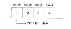
次に、各照明器具にアドレス番号を設定した後で、その設定の確認方法について説明する。人感センサ7を搭載した第1の照明器具6内には、図4に示すようにアドレス設定の有無のデータを書き込みするデータエリアを形成する赤外線信号、例えばアドレス1用〜アドレス4用のデータエリアの赤外線信号が形成する。このデータエリアの各エリアには、初期データとして”0”が書き込まれている。なお、このときに各照明器具の蛍光ランプは全光点灯状態とする。そして、赤外線リモコンからアドレス設定確認開始用の赤外線信号を送信することで、第1の照明器具6にアドレス番号1が設定されている場合には、アドレス1用のデータエリア1に”1”のデータが書き込まれる。なお、ここでアドレス設定の確認を行なう際に赤外線リモコンから赤外線信号を送信する他に、第1の照明器具6にアドレス設定確認開始用スイッチを設け、このスイツチをON動作して行なうようにしても良い。
【0013】
次に、第1の照明器具6内の赤外線信号送信器9からアドレス1用のデータエリア1に”1”のデータが書き込まれ、アドレス2用のデータエリア2〜アドレス4用のデータエリア4に”0”のデータが書き込まれた状態のアドレス設定確認信号を床面に向けて送信する(図1中のa)。第1の照明器具6は、このアドレス設定確認信号の送信時にアドレス番号1が設定されていることを使用者に対して報知するために、蛍光ランプ17の調光度を下降変化させる。そして、第2の照明器具10内の赤外線信号受信器13は床面で反射した赤外線信号即ち前述のアドレス設定確認信号の赤外線信号(図1中のb)を受信する。この後で、第2の照明器具10にアドレス番号2が設定されている場合に、アドレス2用のデータエリア2に”1”のデータが書き込まれる。次に、第2の照明器具10内の赤外線信号送信器14からアドレス1用のデータエリア2及びアドレス2用のデータエリア2に”1”のデータが書き込まれ、アドレス3用のデータエリア3及びアドレス4用のデータエリア4に”0”のデータが書き込まれた状態のアドレス設定確認信号を床面に向けて送信する(図1中のc)。第2の照明器具10は、このアドレス設定データの送信時にアドレス番号2が設定されていることを報知するために、蛍光ランプ21の調光度を下降変化させる。
【0014】
次に、第3の照明器具11内の赤外線信号受信器13は床面で反射したアドレス設定確認信号の赤外線信号(図1中のd)を受信する。この後で、第3の照明器具11にアドレス番号3が設定されている場合に、アドレス3用のデータエリア3に”1”のデータが書き込まれる。そして、第3の照明器具11内の赤外線信号送信器14からアドレス1用のデータエリア1〜アドレス3用のデータエリア3に”1”、アドレス4用のデータエリア4に”0”のデータが書き込まれた状態のアドレス設定確認信号を床面に向けて送信する(図1中のe)。第3の照明器具11は、このアドレス設定データの送信時にアドレス番号3が設定されていることを報知するために、蛍光ランプ21の調光度を下降変化させる。第4の照明器具12のアドレス設定の確認動作についても、前述と同様の方法で行なう。
【0015】
また、使用者が第1の照明器具6〜第4の照明器具12に赤外線リモコンからアドレス番号を設定した際に、例えば第1の照明器具6と第2の照明器具10とにアドレス番号1を誤って重複設定した場合を想定し、これについて説明する。赤外線リモコンから各照明器具にアドレス設定を行なった後で、アドレス設定確認用の赤外線信号を送信する。そして、第1の照明器具6にアドレス番号1が設定している場合に、アドレス1用のデータエリア1に”1”のデータが書き込まれる。次に、第1の照明器具6からアドレス1用のデータエリア1に“1”のデータを書き込んだ状態のアドレス設定確認信号を、第2の照明器具10に送信する。第1の照明器具6は、アドレス設定確認信号の送信時にアドレス番号1が設定していることを報知するために、蛍光ランプ17の調光度を下降変化させる。次に、第2の照明器具10にはアドレス番号1が誤って重複設定され、送信されたアドレス1用のデータエリア1に既に“1”のデータが書き込まれている関係上、第2の照明器具10は”1”のデータをデータエリア1に書き込むことができない。そのため、第2の照明器具10はデータを書き込むことなく、アドレス設定確認信号を第3の照明器具11へ送信する。このとき、第2の照明器具10は既にデータエリア1に”1”のデータが書き込まれていることから、自己照明器具にアドレスが重複設定されていることを認識する。そして、第2の照明器具10はこの状態を報知するために蛍光ランプ21を点滅させる。これ以降の、第3の照明器具11および第4の照明器具12のアドレス設定の確認動作は前述と同様である。
【0016】
また、使用者が第1の照明器具6〜第4の照明器具12に赤外線リモコンからアドレス番号を設定した際に、例えば第2の照明器具10のみにアドレス番号2を未設定した場合を想定し、これについて説明する。赤外線リモコンから各照明器具にアドレス設定を行なった後で、アドレス設定確認用の赤外線信号を送信する。そして、第1の照明器具6にアドレス番号1が設定している場合に、アドレス1用のデータエリア1に”1”のデータが書き込まれ、このアドレス設定確認信号を第2の照明器具10に送信する。このとき、第1の照明器具1はアドレス番号1を設定していることを報知するために、蛍光ランプ17の調光度を下降変化させる。次に、第2の照明器具10はアドレス番号2が未設定であるために、対応するデータエリアを判別することが不可能であるため、何れのデータエリアにもデータ“1”を書き込むことなく、第3の照明器具11にアドレス設定確認信号を送信する。このとき、第2の照明器具10は受信したアドレス設定確認信号の何れのデータエリアにもデータ”1”を書き込んでいない関係上、アドレス番号が未設定であることを報知するために蛍光ランプ21を点滅させる。なお、このときの蛍光ランプ21の点滅時間は前述のアドレス重複を報知する際の蛍光ランプ21の点滅時間よりも例えば遅くするものとし、重複と未設定状態とを区別可能にする。これ以降の、第3の照明器具11および第4の照明器具12のアドレス設定の確認動作は前述と同様である。
【0017】
なお、第1の照明器具6〜第4の照明器具12のアドレス番号の設定確認の動作において、アドレス番号が重複或いは未設定であるかを報知する手段として、前述のように蛍光ランプの点灯状態の変化を利用する他に、可視光LEDなどの表示器を用いて点灯状態を変化するようにしても良い。
【0018】
以上、こうした構成を有する照明システムは赤外線リモコンから各照明器具にアドレス番号を設定し、その後にアドレス番号が各照明器具に対応しているか即ちアドレス番号が重複設定されたり、或いは未設定であるかを蛍光ランプの点灯状態の変化により使用者側へ報知させる構成を有しているので、アドレス設定に際して不具合が有った場合に、速やかに再設定を行なって対処することができる。
【0019】
実施の形態2.
実施の形態2は、アドレス番号の設定確認動作を行う際に、実施の形態1で述べたアドレス設定確認信号の赤外線信号が床面を反射して、その信号を照明器具が受信することが出来るか、即ち照明器具間に赤外線信号の床面反射作用を妨げる物体(机、パーティションなど)が有るかどうかを確認する方法を述べたものである。図1に示す照明システムの運用図において、第1の照明器具6〜第4の照明器具12に照明器具を特定するアドレス番号を設定した後で、アドレス番号の確認動作を開始する。なお、ここではアドレス番号設定の確認動作前では、各照明器具内の蛍光ランプの点灯状態が全光点灯状態とする。次に、アドレス番号の設定の確認動作を開始すると、実施の形態1と同様に第1の照明器具6からアドレス設定データを含む赤外線信号が第2の照明器具10へ送信される。第1の照明器具6は、このアドレス設定データの送信時にアドレス番号1が設定されていることを報知するために、蛍光ランプ17の調光度を下降変化させる。
【0020】
次に、第2の照明器具10からアドレス設定確認信号の赤外線信号が第3の照明器具11に送信され、これと同時に第2の照明器具10はアドレス番号2が設定されていることを報知するために、蛍光ランプ21の調光度を下降変化させる。そして、第2の照明器具10からアドレス設定確認信号の赤外線信号を第3の照明器具11へ送信する際に、これらの照明器具間に床面反射作用によるアドレス設定確認信号の送信を妨げる例えば机、パーティションなどが存在した場合には、そのデータが第3の照明器具11へに到達しない。したがって、第3の照明器具11はアドレス設定確認信号の赤外線信号を受信することが不可能な状態であるために、蛍光ランプ21は全光点灯状態を続行する。また、第4の照明器具12についても第3の照明器具11からアドレス設定データを受信することが不可能なために、蛍光ランプ21は全光点灯状態を続行する。
【0021】
以上、こうした構成を有する照明システムは各照明器具にアドレス番号を設定した後で、アドレス番号の確認動作を行なう際に、アドレス設定データを含む赤外線信号の床面反射作用による受信を妨げる物体が存在するかどうかを確認する方法を採用しているので、受信の不具合状態を速やかに把握することができる。したがって、赤外線信号の受信を妨げる物体の移動、撤去などを迅速に行って照明器具間での赤外線による通信がスムーズとなるように対処できる。
【0022】
実施の形態3.
実施の形態3は、照明器具のアドレス番号の設定確認の動作を行なった後で、天井面に設置された照明器具の合計台数を各照明器具が認識し、実用運転時における点灯命令信号の赤外線信号を効率良く送信する方法について述べたものである。図5に示す照明システムの運用図において、第1の照明器具6〜第4の照明器具12のアドレス番号の設定確認の動作におけるアドレス設定確認信号の送信は、実施の形態1と同様にa〜fの昇順路で行なわれる。そして、第4の照明器具12はアドレス番号4が設定されたと確認した場合に、アドレス4用のデータエリア4に“1”のデータを書き込みし、蛍光ランプ21の調光度を下降変化させる。次に、データエリア1〜データエリア4に”1”のデータが書き込まれたアドレス設定データを、第4の照明器具12から第3の照明器具11へ、第3の照明器具11から第2の照明器具10へ、さらに第2の照明器具10から第1の照明器具6へ、f′〜a′の降順路で送信する。
【0023】
次に、第1の照明器具6は前述のf′〜a′の降順路で送信されたアドレス設定データに基づいて、照明システムを構築する照明器具の設置台数を把握する。例えば、送信されたデータエリア1〜データエリア4に“1”のデータが書き込まれている場合に、第1の照明器具6は4台の照明器具が天井面に設置していると認識する。また、送信されたデータエリア1〜データエリア50に“1”のデータが書き込まれている場合に、第1の照明器具6は50台の照明器具が天井面に設置していると認識する。さらに、送信されたデータエリア1〜データエリア100に“1”のデータが書き込まれている場合に、第1の照明器具6は100台の照明器具が天井面に設置していると認識する。
【0024】
次に、第1の照明器具6は照明器具の全設置台数のデータを赤外線信号によって第2の照明器具10へ、第2の照明器具10は第3の照明器具11へ、さらに第3の照明器具11は第4の照明器具12へ、a〜fの昇順路で送信する。そして、各照明器具が照明システムを構築する照明器具の全設置台数を認識した上で、実用運転時において第1の照明器具6内の人感センサ(図示なし)が人体を検知し、点灯命令信号である赤外線信号を各照明器具へ送信し、他の照明器具とでその点灯命令信号の送受信を行っている過程で、再度人感センサが人体を検知した場合に近傍配置の他の照明器具へ再点灯命令信号を送信するまでの時間を決定する。人体の再検知による再点灯命令信号を送信するまでの時間tは、初回に点灯命令信号を送信した直後からt=赤外線信号の送信所要時間(0.2秒)×設置台数の時間を要する経過時間である。例えば、照明器具の設置台数が4台の場合において、前述の時間tの算出式に基づいて第1の照明器具6が点灯命令信号を送信した後で、0.8秒以内に再度人体検知しても、再点灯命令信号の送信は即座に行なわず、0.8秒の時間を待機してその信号を送信する。
【0025】
また、照明器具の設置台数が50台の場合には前述の時間tの算出式に基づいて、第2の照明器具0は10秒の時間を待機して再点灯命令信号を送信する。さらに、照明器具の設置台数が100台の場合には前述の時間tの算出式に基づいて、20秒の時間を待機して再点灯命令信号を送信する。このように、各照明器具は点灯命令信号を送信し、その後で所定時間内に他の照明器具から再点灯命令信号を受信した場合に、時間tを待機して再点灯命令信号を送信するシステム構成を採用している。
【0026】
したがって、初回時に照明器具間を点灯命令信号が床面を介して送信し、点灯命令信号が最後部の照明器具へ送信し終わった後で、再度点灯命令信号を送信することができる。これにより、複数の照明器具から点灯命令信号が同時に送信されることがなく、信号の干渉作用による送信エラーを未然に防止することができる。さらに、各照明器具がレイアウト変更に伴う照明器具の設置台数の変更に応じて再点灯命令信号を送信するまでの時間を自己認識する構成を有しているので、設置台数が比較的少ない場合には照明システム全体における再点灯命令信号の所要時間を最適に設定することができる。
【0027】
以上、こうした構成を有する照明システムは各照明器具が点灯命令信号を送信する際に、照明器具間に跨ってその信号を同時に送信させることがないために、点灯命令信号の送信エラーを防止すると共に、照明システム全体における照明器具の点灯命令信号の所要時間を設置台数に応じて適宜変更し、最適に設定することができる。
【0028】
【発明の効果】
この発明は、以上説明したように構成されているので、以下に記載されるような効果を奏する。
【0029】
この発明に係る照明システムは、天井面に隣接して照明制御部を備え、それぞれ異なるアドレスが設定される照明器具を複数台設置し、照明器具間に制御信号を、無線送信して照明制御部を制御するようにした照明システムにおいて、各照明器具のそれぞれは、照明器具を特定するアドレス番号をリモコンから受信する受信器と、この受信器で受信したアドレス番号を設定するアドレス設定部と、このアドレス設定部により設定されたアドレスが他の照明器具と重複していないか、また、アドレス設定部に対してアドレスの未設定が無いかを確認するアドレス確認手段と、蛍光ランプの点灯状態を変化させ、アドレスの設定が正常に行なわれてアドレスの重複設定およびアドレスの未設定がないことを報知する報知手段と、隣接する他の照明器具へ所定の信号を無線送信により送信する送信器とを備え、受信器は、アドレス設定確認の際に、一列に配置された照明器具の一端側から他端側に無線送信により順次送信される、各アドレス番号に対応した各データエリアを形成するアドレス確認用の信号を受信器で受信し、アドレス確認手段は、アドレス設定部により既にアドレス番号が設定されている場合であって、且つ受信器で受信したアドレス確認用信号の該当のデータエリアに所定のデータが書き込まれていない場合には、アドレス確認用信号の該当のデータエリアに所定のデータを書き込み、その書き込み後のアドレス確認用信号を送信器から送信させ、また、アドレス設定部によりアドレス番号が設定されていないアドレス未設定の場合又は該当のデータエリアに既に所定のデータが書き込まれているアドレス重複設定の場合には、受信したアドレス確認用信号をそのまま送信器から送信させ、報知手段は、アドレス確認手段でアドレス確認用信号の該当のデータエリアに所定のデータを書き込み、その書き込み後のアドレス確認用信号を送信器から送信した場合、自己の照明器具の蛍光ランプの点灯状態を、第1の点灯状態から第2の点灯状態に変化させ、アドレス未設定又はアドレス重複設定の場合、自己の照明器具の蛍光ランプの点灯状態を、アドレス未設定又はアドレス重複設定であることを示すように第1の点灯状態から第3の点灯状態に変化させるようにしたので、アドレス番号が重複設定されたり、或いは未設定であるかを迅速に確認し、仮に不具合が有った場合には照明器具へのアドレスを再設定して対処することができる。したがって、アドレス設定に際して不具合が有った場合に速やかに再設定を行なって対処することができる。
また、使用者は例えば蛍光ランプの点滅状態によりアドレス番号が重複設定、或いは未設定であるかを容易に判別して、アドレス番号を再設定することができる。
【0030】
また、アドレス確認手段は、外部からアドレス確認用信号が入力されない場合に、照明器具の蛍光ランプを、第1の点灯状態を継続させることで外部からアドレス確認用信号が入力されないことを報知する報知手段を設けたので、アドレス番号の確認を行なう際にアドレス設定データを含む赤外線信号の床面反射作用による受信を妨げる物体、例えば机、パーティションなどの存在を確認し、受信の不具合を速やかに把握することができる。これにより、送信を妨げる物体の移動、撤去などを行って、照明器具間での赤外線の受信がスムーズとなるように対処できる。
【0031】
また、書き込み手段により書き込まれたデータ数をカウントするカウント手段を設け、カウント手段でカウントされたデータ数に基づいて照明器具の台数を認識する台数認識手段を設け、台数認識手段で認識した照明器具の台数を隣接する他の照明器具へ伝達する伝達手段を設け、台数認識手段で認識された照明器具の設置台数又は伝達手段で伝達された信号により、自己の照明器具が他の照明器具へ制御信号を送信するまでの時間を決定する決定手段を設けるようにしたので、各照明器具が再点灯命令信号を送信する際に赤外線信号の干渉により発生する送信エラーを解消し、かつ照明器具間の再点灯命令信号の所要時間を設置台数に応じて適宜変更し、最適に設定することができる。
【図面の簡単な説明】
【図1】 この発明の照明システムに係る実施の形態1を示す運用図である。
【図2】 実施の形態1の照明システムを示す回路ブロック図である。
【図3】 実施の形態1の他の照明システムを示す回路ブロック図である。
【図4】 実施の形態1に係るアドレス設定データの一例である。
【図5】 実施の形態3の照明システムを示す運用図である。
【図6】 従来の照明システムを示す構成図である。
【符号の説明】
1 照明コントローラ、2 信号線、3 照明器具、4 蛍光ランプ、5 人感センサ、6 第1の照明器具、7 人感センサ、8 赤外線信号受信器、9 赤外線信号送信器、10 第2の照明器具、11 第3の照明器具、12 第4の照明器具、13 赤外線信号受信器、14 赤外線信号送信器、15 制御部、16 インバータ、17 蛍光ランプ、18 アドレス番号設定部、19 制御部、20 インバータ、21 蛍光ランプ、22 アドレス番号設定部。[0001]
BACKGROUND OF THE INVENTION
The present invention relates to a lighting system that controls lighting of a plurality of lighting fixtures arranged on a ceiling surface by a control signal.
[0002]
[Prior art]
FIG. 6 is a configuration diagram showing a conventional general illumination system. In FIG. 6,
[0003]
[Problems to be solved by the invention]
However, the conventional lighting system employs a configuration in which a fluorescent lamp is turned on and off by directly connecting a lighting controller and a plurality of lighting fixtures and a plurality of lighting fixtures with signal lines. However, there are problems such as requiring a lot of construction work and a lot of construction costs when installing additional lighting fixtures or changing indoor layouts. It was.
[0004]
The present invention has been made to solve the above-described problems. A signal line for connecting a plurality of lighting fixtures is not necessary, and the facility construction of the lighting fixture can be easily performed. Provided is an illumination system that sets address information for identifying an individual, makes it easy to change a group of lighting fixtures when a room layout is changed, and has a confirmation function for confirming whether the address information is correctly set Is.
[0005]
[Means for Solving the Problems]
An illumination system according to the present invention includes an illumination control unit adjacent to a ceiling surface., Different addresses are set In a lighting system in which a plurality of lighting fixtures are installed and a control signal is wirelessly transmitted between the lighting fixtures to control the lighting control unit, each lighting fixture assigns an address number for identifying the lighting fixture from a remote controller. The receiver to receive, the address setting unit for setting the address number received by this receiver, whether the address set by this address setting unit does not overlap with other lighting fixtures, and to the address setting unit Address confirmation means for confirming that there is no unset address,Change the lighting state of the fluorescent lamp, Informing means for notifying that address setting is normally performed and there is no address duplication setting and address non-setting, and a transmitter for transmitting a predetermined signal to other adjacent lighting fixtures by wireless transmission, The receiverWhen checking the address settings, from one end of the lighting fixtures arranged in a row to the other end When the receiver receives a signal for address confirmation that forms each data area corresponding to each address number, which is sequentially transmitted by wireless transmission, and the address confirmation means has already set the address number by the address setting unit If the predetermined data is not written in the corresponding data area of the address confirmation signal received by the receiver, the predetermined data is written in the corresponding data area of the address confirmation signal and the data is written. Send a later address confirmation signal from the transmitter, and if the address setting unit has not set an address number or the address has not been set, or the specified data has already been written to the corresponding data area. In this case, the received address confirmation signal is transmitted as it is from the transmitter, and the notification meansWhen predetermined data is written in the corresponding data area of the address confirmation signal by the address confirmation means, and the address confirmation signal after the writing is transmitted from the transmitter, the lighting state of the fluorescent lamp of the own lighting fixture is changed to the first state. From the lighting state of to the second lighting state, If the address is not set or the address is duplicated, the lighting state of the fluorescent lamp of its own lighting fixture indicates that the address is not set or the address is duplicated.From the first lighting state to the third lighting state It is intended to change.
[0006]
In addition, the address confirmation means can detect the fluorescent lamp of the lighting fixture when no address confirmation signal is input from the outside.By continuing the first lighting state Informing means for informing that an address confirmation signal is not inputted from the outside is provided.
[0007]
Also,Count means for counting the number of data written by the writing means, number recognition means for recognizing the number of lighting fixtures based on the number of data counted by the counting means, and the number of lighting fixtures recognized by the number recognition means Is transmitted to other adjacent lighting fixtures, and the number of installed lighting fixtures recognized by the number recognition unit or the signal transmitted by the transmission means, the own lighting fixture transmits a control signal to the other lighting fixtures. And a determination means for determining the time until Is.
[0009]
DETAILED DESCRIPTION OF THE INVENTION
1 is a block diagram showing an illumination system according to
FIG. 2 is a block diagram showing a circuit configuration of the first lighting fixture 6 on which the human sensor 7 is mounted. In FIG. 2, when the human body detection signal from the human sensor 7 is input, the
[0010]
FIG. 3 is a block diagram showing a circuit configuration of the
[0011]
Next, an address number setting method and a setting confirmation method for each lighting fixture in the lighting system having such a configuration will be described with reference to the operation diagram of the lighting system shown in FIG. 1 and the block diagrams shown in FIGS. In FIG. 1 to FIG. 3, the address number for identifying each lighting fixture in the address
[0012]
Next, after setting an address number for each lighting fixture, a method for confirming the setting will be described. In the first lighting fixture 6 equipped with the human sensor 7, as shown in FIG. 4, an infrared signal forming a data area for writing data indicating presence / absence of address setting, for example, data for
[0013]
Next, “1” data is written in the
[0014]
Next, the
[0015]
When the user sets an address number from the infrared remote controller to the first lighting fixture 6 to the
[0016]
In addition, when the user sets an address number from the infrared remote controller to the first lighting fixture 6 to the
[0017]
In addition, in the operation of confirming the address number setting of the first lighting fixture 6 to the
[0018]
As described above, in the lighting system having such a configuration, an address number is set to each lighting fixture from the infrared remote controller, and then the address number corresponds to each lighting fixture, that is, whether the address number is duplicated or not set. Is notified to the user by the change in the lighting state of the fluorescent lamp, so that if there is a problem in the address setting, it can be quickly reset and dealt with.
[0019]
In the second embodiment, when the address number setting confirmation operation is performed, the infrared signal of the address setting confirmation signal described in the first embodiment reflects the floor surface, and the lighting apparatus can receive the signal. That is, a method for confirming whether or not there is an object (a desk, a partition, etc.) that hinders the floor reflection of the infrared signal between the lighting fixtures. In the operation diagram of the lighting system shown in FIG. 1, an address number confirmation operation is started after an address number for specifying the lighting fixture is set in the first lighting fixture 6 to the
[0020]
Next, the infrared signal of the address setting confirmation signal is transmitted from the
[0021]
As described above, in the lighting system having such a configuration, there is an object that prevents the reception of the infrared signal including the address setting data due to the floor reflection effect when the address number is confirmed after setting the address number for each lighting fixture. Since the method of confirming whether or not to do so is adopted, it is possible to quickly grasp the reception failure state. Accordingly, it is possible to quickly move and remove an object that hinders reception of an infrared signal so that infrared communication between the luminaires can be performed smoothly.
[0022]
In the third embodiment, after the operation of confirming the setting of the address number of the lighting fixture is performed, each lighting fixture recognizes the total number of lighting fixtures installed on the ceiling surface, and the infrared of the lighting command signal during practical operation A method for efficiently transmitting a signal is described. In the operation diagram of the lighting system shown in FIG. 5, transmission of the address setting confirmation signal in the operation of confirming the setting of the address numbers of the first lighting fixture 6 to the
[0023]
Next, the 1st lighting fixture 6 grasps | ascertains the installation number of the lighting fixtures which construct | assemble a lighting system based on the address setting data transmitted by the above-mentioned descending path of f'-a '. For example, when “1” data is written in the transmitted
[0024]
Next, the first lighting fixture 6 sends data of the total number of installed lighting fixtures to the
[0025]
When the number of installed lighting fixtures is 50, the second lighting fixture 0 waits for a time of 10 seconds and transmits a relighting command signal based on the above-described calculation formula for time t. Further, when the number of installed lighting fixtures is 100, a relighting command signal is transmitted after waiting for a time of 20 seconds based on the above-described formula for calculating time t. As described above, when each lighting fixture transmits a lighting command signal and then receives a lighting command signal from another lighting fixture within a predetermined time, the system waits for time t and transmits the lighting command signal. The configuration is adopted.
[0026]
Therefore, a lighting command signal can be transmitted between the lighting fixtures through the floor at the first time, and after the lighting command signal has been sent to the last lighting fixture, the lighting command signal can be transmitted again. Thereby, a lighting command signal is not transmitted simultaneously from a some lighting fixture, and the transmission error by the interference effect of a signal can be prevented beforehand. In addition, each lighting fixture has a configuration that self-recognizes the time until a relighting command signal is transmitted in response to a change in the number of installed lighting fixtures due to a layout change. Can optimally set the time required for the relighting command signal in the entire lighting system.
[0027]
As described above, the lighting system having such a configuration prevents a lighting command signal transmission error because each lighting device does not transmit the lighting command signal across the lighting fixtures at the same time. The time required for the lighting command signal of the lighting fixture in the entire lighting system can be appropriately changed according to the number of installed units, and can be set optimally.
[0028]
【The invention's effect】
Since the present invention is configured as described above, the following effects can be obtained.
[0029]
An illumination system according to the present invention includes an illumination control unit adjacent to a ceiling surface., Different addresses are set In a lighting system in which a plurality of lighting fixtures are installed and a control signal is wirelessly transmitted between the lighting fixtures to control the lighting control unit, each lighting fixture assigns an address number for identifying the lighting fixture from a remote controller. The receiver to receive, the address setting unit for setting the address number received by this receiver, whether the address set by this address setting unit does not overlap with other lighting fixtures, and to the address setting unit Address confirmation means for confirming that there is no unset address,Change the lighting state of the fluorescent lamp, Informing means for notifying that address setting is normally performed and there is no address duplication setting and address non-setting, and a transmitter for transmitting a predetermined signal to other adjacent lighting fixtures by wireless transmission, The receiverWhen checking the address settings, from one end of the lighting fixtures arranged in a row to the other end When the receiver receives a signal for address confirmation that forms each data area corresponding to each address number, which is sequentially transmitted by wireless transmission, and the address confirmation means has already set the address number by the address setting unit If the predetermined data is not written in the corresponding data area of the address confirmation signal received by the receiver, the predetermined data is written in the corresponding data area of the address confirmation signal and the data is written. Send a later address confirmation signal from the transmitter, and if the address setting unit has not set an address number or the address has not been set, or the specified data has already been written to the corresponding data area. In this case, the received address confirmation signal is transmitted as it is from the transmitter, and the notification meansWhen predetermined data is written in the corresponding data area of the address confirmation signal by the address confirmation means, and the address confirmation signal after the writing is transmitted from the transmitter, the lighting state of the fluorescent lamp of the own lighting fixture is changed to the first state. From the lighting state of to the second lighting state, If the address is not set or the address is duplicated, the lighting state of the fluorescent lamp of its own lighting fixture indicates that the address is not set or the address is duplicated.From the first lighting state to the third lighting state Because it was changed, it is possible to quickly check whether the address number is duplicated or not set, and if there is a problem, reset the address to the lighting fixture and deal with it it can. Therefore, if there is a problem in address setting, it can be quickly reset and dealt with.
Further, the user can easily determine whether the address number is duplicated or not set, for example, according to the blinking state of the fluorescent lamp, and can reset the address number.
[0030]
In addition, the address confirmation means can detect the fluorescent lamp of the lighting fixture when no address confirmation signal is input from the outside.By continuing the first lighting state Since the notification means for notifying that the address confirmation signal is not input from the outside is provided, an object that prevents reception of the infrared signal including the address setting data by the floor surface reflection action when confirming the address number, for example, a desk or partition Etc. can be confirmed, and reception failures can be quickly grasped. Accordingly, it is possible to cope with the smooth reception of infrared rays between the luminaires by moving or removing an object that hinders transmission.
[0031]
Also,book A counting means for counting the number of data written by the writing means is provided, a number recognizing means for recognizing the number of lighting fixtures based on the number of data counted by the counting means, and a number of lighting fixtures recognized by the number recognizing means. A transmission means is provided for transmitting the number of units to other adjacent lighting fixtures. The number of installed lighting fixtures recognized by the number recognition unit or a signal transmitted by the transmission means causes a control signal from the lighting fixture to be transmitted to the other lighting fixtures. Since the determination means for determining the time until the transmission of the light is transmitted, the transmission error caused by the interference of the infrared signal when each lighting apparatus transmits the re-lighting command signal is eliminated, and the re-intermission between the lighting apparatuses is performed. The required time of the lighting command signal can be changed as appropriate according to the number of installed units, and can be set optimally.
[Brief description of the drawings]
FIG. 1 is an operation
FIG. 2 is a circuit block diagram illustrating the lighting system according to the first embodiment.
FIG. 3 is a circuit block diagram showing another lighting system of the first embodiment.
4 is an example of address setting data according to the first embodiment. FIG.
FIG. 5 is an operation diagram showing a lighting system according to a third embodiment.
FIG. 6 is a block diagram showing a conventional illumination system.
[Explanation of symbols]
DESCRIPTION OF
Claims (3)
Translated fromJapanese各照明器具のそれぞれは、照明器具を特定するアドレス番号をリモコンから受信する受信器と、この受信器で受信したアドレス番号を設定するアドレス設定部と、このアドレス設定部により設定されたアドレスが他の照明器具と重複していないか、また、前記アドレス設定部に対してアドレスの未設定が無いかを確認するアドレス確認手段と、前記蛍光ランプの点灯状態を変化させ、アドレスの設定が正常に行なわれてアドレスの重複設定およびアドレスの未設定がないことを報知する報知手段と、隣接する他の照明器具へ所定の信号を無線送信により送信する送信器とを備え、
前記受信器は、アドレス設定確認の際に、一列に配置された照明器具の一端側から他端側に無線送信により順次送信される、各アドレス番号に対応した各データエリアを形成するアドレス確認用の信号を前記受信器で受信し、
前記アドレス確認手段は、前記アドレス設定部により既にアドレス番号が設定されている場合であって、且つ前記受信器で受信したアドレス確認用信号の該当のデータエリアに所定のデータが書き込まれていない場合には、前記アドレス確認用信号の前記該当のデータエリアに所定のデータを書き込み、その書き込み後のアドレス確認用信号を前記送信器から送信させ、また、前記アドレス設定部によりアドレス番号が設定されていないアドレス未設定の場合又は該当のデータエリアに既に所定のデータが書き込まれているアドレス重複設定の場合には、前記受信したアドレス確認用信号をそのまま前記送信器から送信させ、
前記報知手段は、前記アドレス確認手段で前記アドレス確認用信号の前記該当のデータエリアに所定のデータを書き込み、その書き込み後のアドレス確認用信号を前記送信器から送信した場合、自己の照明器具の蛍光ランプの点灯状態を、第1の点灯状態から第2の点灯状態に変化させ、前記アドレス未設定又は前記アドレス重複設定の場合、自己の照明器具の蛍光ランプの点灯状態を、アドレス未設定又はアドレス重複設定であることを示すように前記第1の点灯状態から第3の点灯状態に変化させることを特徴とする照明システム。A lighting control unit is provided adjacent to the ceiling surface, and a plurality of lighting fixtureseach having a different address are installed, and a control signal is wirelessly transmitted between the lighting fixtures to control the lighting control unit. In the lighting system,
Each of the lighting fixtures includes a receiver that receives an address number identifying the lighting fixture from the remote control, an address setting unit that sets the address number received by the receiver, and an address set by the address setting unit. The address setting means for confirming whether there is no overlap with the lighting fixtures and whether the address setting unit has not been set with an address,and changing the lighting state of the fluorescent lamp so that the address is set correctly. An informing means for notifying that there is no address overlap setting and no address setting, and a transmitter for transmitting a predetermined signal by radio transmission to other adjacent lighting fixtures,
When theaddress setting is confirmed , the receiver is sequentially transmitted by radio transmissionfrom one end side of the lighting fixtures arranged in a row to the other end side, for address confirmation that forms each data area corresponding to each address number Is received by the receiver,
The address confirmation means is a case where an address number has already been set by the address setting unit, and predetermined data is not written in the corresponding data area of the address confirmation signal received by the receiver The predetermined data is written in the corresponding data area of the address confirmation signal, the address confirmation signal after the writing is transmitted from the transmitter, and an address number is set by the address setting unit. In the case of no address not set or in the case of address duplication setting where predetermined data has already been written in the corresponding data area, the received address confirmation signal is transmitted as it is from the transmitter,
The notification meanswrites predetermined data in the corresponding data area of the address confirmation signal by the address confirmation means, and transmits the address confirmation signal after the writing from the transmitter. When the lighting state of the fluorescent lamp is changed from the first lighting state to the second lighting state, and the address is not set or the address is overlapped, the lighting state of the fluorescent lamp of its own lighting fixture is not set or The lighting system is characterized in thatthe first lighting state is changedto the third lighting state so as to indicate the address duplication setting.
Priority Applications (1)
| Application Number | Priority Date | Filing Date | Title |
|---|---|---|---|
| JP2001378082AJP4232139B2 (en) | 2001-12-12 | 2001-12-12 | Lighting system |
Applications Claiming Priority (1)
| Application Number | Priority Date | Filing Date | Title |
|---|---|---|---|
| JP2001378082AJP4232139B2 (en) | 2001-12-12 | 2001-12-12 | Lighting system |
Publications (2)
| Publication Number | Publication Date |
|---|---|
| JP2003178889A JP2003178889A (en) | 2003-06-27 |
| JP4232139B2true JP4232139B2 (en) | 2009-03-04 |
Family
ID=19185903
Family Applications (1)
| Application Number | Title | Priority Date | Filing Date |
|---|---|---|---|
| JP2001378082AExpired - LifetimeJP4232139B2 (en) | 2001-12-12 | 2001-12-12 | Lighting system |
Country Status (1)
| Country | Link |
|---|---|
| JP (1) | JP4232139B2 (en) |
Families Citing this family (17)
| Publication number | Priority date | Publication date | Assignee | Title |
|---|---|---|---|---|
| JP4640634B2 (en)* | 2004-11-15 | 2011-03-02 | 東芝ライテック株式会社 | Disaster prevention lighting equipment with automatic inspection function and disaster prevention lighting equipment control system |
| JP4548275B2 (en)* | 2005-08-23 | 2010-09-22 | パナソニック電工株式会社 | Emergency light automatic inspection system |
| US10070501B2 (en) | 2012-04-05 | 2018-09-04 | Panasonic Intellectual Property Management Co., Ltd. | Lighting system and support apparatus |
| US9980350B2 (en) | 2012-07-01 | 2018-05-22 | Cree, Inc. | Removable module for a lighting fixture |
| US10219338B2 (en) | 2012-07-01 | 2019-02-26 | Cree, Inc. | Modular lighting control |
| US9872367B2 (en) | 2012-07-01 | 2018-01-16 | Cree, Inc. | Handheld device for grouping a plurality of lighting fixtures |
| US10721808B2 (en) | 2012-07-01 | 2020-07-21 | Ideal Industries Lighting Llc | Light fixture control |
| US9572226B2 (en) | 2012-07-01 | 2017-02-14 | Cree, Inc. | Master/slave arrangement for lighting fixture modules |
| CN104982093B (en)* | 2012-12-18 | 2018-07-20 | 科锐 | Lighting device device for distributed AC servo system |
| US9913348B2 (en) | 2012-12-19 | 2018-03-06 | Cree, Inc. | Light fixtures, systems for controlling light fixtures, and methods of controlling fixtures and methods of controlling lighting control systems |
| US10154569B2 (en) | 2014-01-06 | 2018-12-11 | Cree, Inc. | Power over ethernet lighting fixture |
| US9723680B2 (en) | 2014-05-30 | 2017-08-01 | Cree, Inc. | Digitally controlled driver for lighting fixture |
| JP2017212514A (en)* | 2016-05-24 | 2017-11-30 | 株式会社リコー | Communication system, communication device, setting method of identification information, and program |
| US9967944B2 (en) | 2016-06-22 | 2018-05-08 | Cree, Inc. | Dimming control for LED-based luminaires |
| US10595380B2 (en) | 2016-09-27 | 2020-03-17 | Ideal Industries Lighting Llc | Lighting wall control with virtual assistant |
| JP7715011B2 (en)* | 2021-11-02 | 2025-07-30 | 三菱電機株式会社 | Lighting Control System |
| CN116347698A (en)* | 2023-04-10 | 2023-06-27 | 深圳御光新材料有限公司 | Wireless address-writing programmable lamp bead and wireless address-writing programmable lamp string |
- 2001
- 2001-12-12JPJP2001378082Apatent/JP4232139B2/ennot_activeExpired - Lifetime
Also Published As
| Publication number | Publication date |
|---|---|
| JP2003178889A (en) | 2003-06-27 |
Similar Documents
| Publication | Publication Date | Title |
|---|---|---|
| JP4232139B2 (en) | Lighting system | |
| JP4409294B2 (en) | Wireless controlled lighting system initialization | |
| CN1756452B (en) | Setting method of lighting system, setting unit and lighting system | |
| US8049434B2 (en) | Lighting commissioning device and method | |
| JP6223576B2 (en) | Tablet-based commissioning tool for addressable lighting | |
| CN100592838C (en) | Method of configuring a wireless controlled lighting system | |
| TWI511616B (en) | Control system and control method based on synchronous AC power frequency | |
| US8100545B2 (en) | Wireless convenience lighting system and method of making same | |
| US20100237783A1 (en) | Wireless convenience lighting system and method of making same | |
| CN105230129A (en) | Lighting apparatus | |
| JP3918460B2 (en) | Lighting system | |
| JP2008027822A (en) | Illumination control system | |
| JP4811312B2 (en) | Hot wire wireless transmitter and wireless receiver | |
| JP3813881B2 (en) | Lighting system | |
| JP2003347066A (en) | Lighting control system | |
| CN110510468B (en) | Elevator car personnel detection system, elevator, detection method and storage medium | |
| JP2002075663A (en) | Illumination equipment | |
| JP3719019B2 (en) | Lighting device | |
| JP4995607B2 (en) | Hot wire wireless transmitter | |
| JP4980108B2 (en) | Lighting control device | |
| JPH10125475A (en) | Lighting control device | |
| JP2003133083A (en) | Lighting system | |
| JP3921587B2 (en) | Lighting system | |
| JP2003217870A (en) | Lighting equipment | |
| JP6600950B2 (en) | Lighting system |
Legal Events
| Date | Code | Title | Description |
|---|---|---|---|
| RD01 | Notification of change of attorney | Free format text:JAPANESE INTERMEDIATE CODE: A7421 Effective date:20040810 | |
| A977 | Report on retrieval | Free format text:JAPANESE INTERMEDIATE CODE: A971007 Effective date:20060927 | |
| A131 | Notification of reasons for refusal | Free format text:JAPANESE INTERMEDIATE CODE: A131 Effective date:20061003 | |
| A521 | Written amendment | Free format text:JAPANESE INTERMEDIATE CODE: A523 Effective date:20061201 | |
| RD03 | Notification of appointment of power of attorney | Free format text:JAPANESE INTERMEDIATE CODE: A7423 Effective date:20061201 | |
| A131 | Notification of reasons for refusal | Free format text:JAPANESE INTERMEDIATE CODE: A131 Effective date:20070109 | |
| A521 | Written amendment | Free format text:JAPANESE INTERMEDIATE CODE: A523 Effective date:20070305 | |
| A02 | Decision of refusal | Free format text:JAPANESE INTERMEDIATE CODE: A02 Effective date:20070327 | |
| A521 | Written amendment | Free format text:JAPANESE INTERMEDIATE CODE: A523 Effective date:20070525 | |
| A911 | Transfer to examiner for re-examination before appeal (zenchi) | Free format text:JAPANESE INTERMEDIATE CODE: A911 Effective date:20070601 | |
| A912 | Re-examination (zenchi) completed and case transferred to appeal board | Free format text:JAPANESE INTERMEDIATE CODE: A912 Effective date:20070615 | |
| A01 | Written decision to grant a patent or to grant a registration (utility model) | Free format text:JAPANESE INTERMEDIATE CODE: A01 | |
| A61 | First payment of annual fees (during grant procedure) | Free format text:JAPANESE INTERMEDIATE CODE: A61 Effective date:20081127 | |
| FPAY | Renewal fee payment (event date is renewal date of database) | Free format text:PAYMENT UNTIL: 20111219 Year of fee payment:3 | |
| R150 | Certificate of patent or registration of utility model | Free format text:JAPANESE INTERMEDIATE CODE: R150 Ref document number:4232139 Country of ref document:JP Free format text:JAPANESE INTERMEDIATE CODE: R150 | |
| FPAY | Renewal fee payment (event date is renewal date of database) | Free format text:PAYMENT UNTIL: 20111219 Year of fee payment:3 | |
| FPAY | Renewal fee payment (event date is renewal date of database) | Free format text:PAYMENT UNTIL: 20121219 Year of fee payment:4 | |
| FPAY | Renewal fee payment (event date is renewal date of database) | Free format text:PAYMENT UNTIL: 20121219 Year of fee payment:4 | |
| FPAY | Renewal fee payment (event date is renewal date of database) | Free format text:PAYMENT UNTIL: 20131219 Year of fee payment:5 | |
| R250 | Receipt of annual fees | Free format text:JAPANESE INTERMEDIATE CODE: R250 | |
| R250 | Receipt of annual fees | Free format text:JAPANESE INTERMEDIATE CODE: R250 | |
| R250 | Receipt of annual fees | Free format text:JAPANESE INTERMEDIATE CODE: R250 | |
| R250 | Receipt of annual fees | Free format text:JAPANESE INTERMEDIATE CODE: R250 | |
| R250 | Receipt of annual fees | Free format text:JAPANESE INTERMEDIATE CODE: R250 | |
| R250 | Receipt of annual fees | Free format text:JAPANESE INTERMEDIATE CODE: R250 | |
| EXPY | Cancellation because of completion of term |