JP4232038B2 - Film-clad electrical device and method for manufacturing the same - Google Patents
Film-clad electrical device and method for manufacturing the sameDownload PDFInfo
- Publication number
- JP4232038B2 JP4232038B2JP2004234524AJP2004234524AJP4232038B2JP 4232038 B2JP4232038 B2JP 4232038B2JP 2004234524 AJP2004234524 AJP 2004234524AJP 2004234524 AJP2004234524 AJP 2004234524AJP 4232038 B2JP4232038 B2JP 4232038B2
- Authority
- JP
- Japan
- Prior art keywords
- film
- heat
- electrical device
- exterior
- cross
- Prior art date
- Legal status (The legal status is an assumption and is not a legal conclusion. Google has not performed a legal analysis and makes no representation as to the accuracy of the status listed.)
- Expired - Fee Related
Links
- 238000004519manufacturing processMethods0.000titleclaimsdescription17
- 238000000034methodMethods0.000titleclaimsdescription14
- 229920005989resinPolymers0.000claimsdescription146
- 239000011347resinSubstances0.000claimsdescription146
- 230000004927fusionEffects0.000claimsdescription101
- 238000007789sealingMethods0.000claimsdescription81
- 238000004132cross linkingMethods0.000claimsdescription40
- 238000003860storageMethods0.000claimsdescription32
- 238000010894electron beam technologyMethods0.000claimsdescription27
- 230000002093peripheral effectEffects0.000claimsdescription13
- 230000001678irradiating effectEffects0.000claimsdescription5
- 239000010408filmSubstances0.000description165
- 239000010410layerSubstances0.000description118
- 229910052751metalInorganic materials0.000description15
- 239000002184metalSubstances0.000description15
- 229920000642polymerPolymers0.000description9
- 150000001875compoundsChemical class0.000description7
- 229910052782aluminiumInorganic materials0.000description6
- 239000003990capacitorSubstances0.000description6
- 239000011888foilSubstances0.000description6
- 238000000926separation methodMethods0.000description6
- RYGMFSIKBFXOCR-UHFFFAOYSA-NCopperChemical compound[Cu]RYGMFSIKBFXOCR-UHFFFAOYSA-N0.000description5
- PXHVJJICTQNCMI-UHFFFAOYSA-NNickelChemical compound[Ni]PXHVJJICTQNCMI-UHFFFAOYSA-N0.000description5
- XAGFODPZIPBFFR-UHFFFAOYSA-NaluminiumChemical compound[Al]XAGFODPZIPBFFR-UHFFFAOYSA-N0.000description5
- 229920006037cross link polymerPolymers0.000description5
- 239000003792electrolyteSubstances0.000description5
- XEEYBQQBJWHFJM-UHFFFAOYSA-NironSubstances[Fe]XEEYBQQBJWHFJM-UHFFFAOYSA-N0.000description5
- 239000000463materialSubstances0.000description5
- -1polyethylene terephthalatePolymers0.000description5
- NIXOWILDQLNWCW-UHFFFAOYSA-MAcrylateChemical compound[O-]C(=O)C=CNIXOWILDQLNWCW-UHFFFAOYSA-M0.000description4
- NIXOWILDQLNWCW-UHFFFAOYSA-Nacrylic acid groupChemical groupC(C=C)(=O)ONIXOWILDQLNWCW-UHFFFAOYSA-N0.000description4
- 239000013078crystalSubstances0.000description4
- 239000008151electrolyte solutionSubstances0.000description4
- 229910052744lithiumInorganic materials0.000description4
- 239000005022packaging materialSubstances0.000description4
- 229920000098polyolefinPolymers0.000description4
- 239000011342resin compositionSubstances0.000description4
- WHXSMMKQMYFTQS-UHFFFAOYSA-NLithiumChemical compound[Li]WHXSMMKQMYFTQS-UHFFFAOYSA-N0.000description3
- 238000006243chemical reactionMethods0.000description3
- 230000000052comparative effectEffects0.000description3
- 229910052802copperInorganic materials0.000description3
- 239000010949copperSubstances0.000description3
- 239000007772electrode materialSubstances0.000description3
- 239000005001laminate filmSubstances0.000description3
- 229910052759nickelInorganic materials0.000description3
- 239000011255nonaqueous electrolyteSubstances0.000description3
- 239000011241protective layerSubstances0.000description3
- 239000000126substanceSubstances0.000description3
- VXNZUUAINFGPBY-UHFFFAOYSA-N1-ButeneChemical compoundCCC=CVXNZUUAINFGPBY-UHFFFAOYSA-N0.000description2
- LYCAIKOWRPUZTN-UHFFFAOYSA-NEthylene glycolChemical compoundOCCOLYCAIKOWRPUZTN-UHFFFAOYSA-N0.000description2
- HBBGRARXTFLTSG-UHFFFAOYSA-NLithium ionChemical compound[Li+]HBBGRARXTFLTSG-UHFFFAOYSA-N0.000description2
- PPBRXRYQALVLMV-UHFFFAOYSA-NStyreneChemical compoundC=CC1=CC=CC=C1PPBRXRYQALVLMV-UHFFFAOYSA-N0.000description2
- 230000005856abnormalityEffects0.000description2
- 239000000853adhesiveSubstances0.000description2
- 230000001070adhesive effectEffects0.000description2
- 239000012298atmosphereSubstances0.000description2
- 229920001577copolymerPolymers0.000description2
- 239000011889copper foilSubstances0.000description2
- 238000000354decomposition reactionMethods0.000description2
- 230000007423decreaseEffects0.000description2
- 230000000694effectsEffects0.000description2
- 239000005038ethylene vinyl acetateSubstances0.000description2
- 229920006244ethylene-ethyl acrylatePolymers0.000description2
- 229920006225ethylene-methyl acrylatePolymers0.000description2
- 229910052742ironInorganic materials0.000description2
- 229910001416lithium ionInorganic materials0.000description2
- 238000002844meltingMethods0.000description2
- 230000008018meltingEffects0.000description2
- 239000007769metal materialSubstances0.000description2
- 239000000203mixtureSubstances0.000description2
- 238000012986modificationMethods0.000description2
- 230000004048modificationEffects0.000description2
- 229920001200poly(ethylene-vinyl acetate)Polymers0.000description2
- 229920005992thermoplastic resinPolymers0.000description2
- 239000010409thin filmSubstances0.000description2
- 239000010936titaniumSubstances0.000description2
- 229910052719titaniumInorganic materials0.000description2
- MYWOJODOMFBVCB-UHFFFAOYSA-N1,2,6-trimethylphenanthreneChemical compoundCC1=CC=C2C3=CC(C)=CC=C3C=CC2=C1CMYWOJODOMFBVCB-UHFFFAOYSA-N0.000description1
- MZNSQRLUUXWLSB-UHFFFAOYSA-N2-ethenyl-1h-pyrroleChemical compoundC=CC1=CC=CN1MZNSQRLUUXWLSB-UHFFFAOYSA-N0.000description1
- KGIGUEBEKRSTEW-UHFFFAOYSA-N2-vinylpyridineChemical compoundC=CC1=CC=CC=N1KGIGUEBEKRSTEW-UHFFFAOYSA-N0.000description1
- OKTJSMMVPCPJKN-UHFFFAOYSA-NCarbonChemical compound[C]OKTJSMMVPCPJKN-UHFFFAOYSA-N0.000description1
- 239000004593EpoxySubstances0.000description1
- VGGSQFUCUMXWEO-UHFFFAOYSA-NEtheneChemical compoundC=CVGGSQFUCUMXWEO-UHFFFAOYSA-N0.000description1
- 239000005977EthyleneSubstances0.000description1
- 229910000861Mg alloyInorganic materials0.000description1
- GNULGOSSPWDTMD-UHFFFAOYSA-NNC(=O)OCC.C(CCCCCN=C=O)N=C=O.C(C=C)(=O)OCC(COC(C=C)=O)(COC(C=C)=O)COChemical compoundNC(=O)OCC.C(CCCCCN=C=O)N=C=O.C(C=C)(=O)OCC(COC(C=C)=O)(COC(C=C)=O)COGNULGOSSPWDTMD-UHFFFAOYSA-N0.000description1
- 239000004677NylonSubstances0.000description1
- 239000002033PVDF binderSubstances0.000description1
- 239000004698PolyethyleneSubstances0.000description1
- 229920002367PolyisobutenePolymers0.000description1
- 239000004743PolypropyleneSubstances0.000description1
- 229910001069Ti alloyInorganic materials0.000description1
- RTAQQCXQSZGOHL-UHFFFAOYSA-NTitaniumChemical compound[Ti]RTAQQCXQSZGOHL-UHFFFAOYSA-N0.000description1
- ZJCCRDAZUWHFQH-UHFFFAOYSA-NTrimethylolpropaneChemical compoundCCC(CO)(CO)COZJCCRDAZUWHFQH-UHFFFAOYSA-N0.000description1
- XTXRWKRVRITETP-UHFFFAOYSA-NVinyl acetateChemical compoundCC(=O)OC=CXTXRWKRVRITETP-UHFFFAOYSA-N0.000description1
- MPIAGWXWVAHQBB-UHFFFAOYSA-N[3-prop-2-enoyloxy-2-[[3-prop-2-enoyloxy-2,2-bis(prop-2-enoyloxymethyl)propoxy]methyl]-2-(prop-2-enoyloxymethyl)propyl] prop-2-enoateChemical compoundC=CC(=O)OCC(COC(=O)C=C)(COC(=O)C=C)COCC(COC(=O)C=C)(COC(=O)C=C)COC(=O)C=CMPIAGWXWVAHQBB-UHFFFAOYSA-N0.000description1
- KLARSDUHONHPRF-UHFFFAOYSA-N[Li].[Mn]Chemical compound[Li].[Mn]KLARSDUHONHPRF-UHFFFAOYSA-N0.000description1
- 230000002159abnormal effectEffects0.000description1
- 230000004308accommodationEffects0.000description1
- 230000002411adverseEffects0.000description1
- 230000015572biosynthetic processEffects0.000description1
- OJIJEKBXJYRIBZ-UHFFFAOYSA-Ncadmium nickelChemical compound[Ni].[Cd]OJIJEKBXJYRIBZ-UHFFFAOYSA-N0.000description1
- 229910052799carbonInorganic materials0.000description1
- 150000007942carboxylatesChemical class0.000description1
- 239000011248coating agentSubstances0.000description1
- 238000000576coating methodMethods0.000description1
- 238000004891communicationMethods0.000description1
- 239000002131composite materialSubstances0.000description1
- 239000012141concentrateSubstances0.000description1
- 239000003431cross linking reagentSubstances0.000description1
- 238000013461designMethods0.000description1
- 238000005868electrolysis reactionMethods0.000description1
- 239000005042ethylene-ethyl acrylateSubstances0.000description1
- 238000007499fusion processingMethods0.000description1
- 239000011521glassSubstances0.000description1
- 230000012447hatchingEffects0.000description1
- 229920001519homopolymerPolymers0.000description1
- WGCNASOHLSPBMP-UHFFFAOYSA-NhydroxyacetaldehydeNatural productsOCC=OWGCNASOHLSPBMP-UHFFFAOYSA-N0.000description1
- 230000010354integrationEffects0.000description1
- 238000005304joiningMethods0.000description1
- 239000011133leadSubstances0.000description1
- 229920000092linear low density polyethylenePolymers0.000description1
- 239000004707linear low-density polyethyleneSubstances0.000description1
- 229910003002lithium saltInorganic materials0.000description1
- 159000000002lithium saltsChemical class0.000description1
- 229920001684low density polyethylenePolymers0.000description1
- 239000004702low-density polyethyleneSubstances0.000description1
- 239000011159matrix materialSubstances0.000description1
- 238000005259measurementMethods0.000description1
- 229920001179medium density polyethylenePolymers0.000description1
- 239000004701medium-density polyethyleneSubstances0.000description1
- 229910052987metal hydrideInorganic materials0.000description1
- 238000002156mixingMethods0.000description1
- 239000004745nonwoven fabricSubstances0.000description1
- 229920001778nylonPolymers0.000description1
- 229920000728polyesterPolymers0.000description1
- 229920000573polyethylenePolymers0.000description1
- 229920000139polyethylene terephthalatePolymers0.000description1
- 239000005020polyethylene terephthalateSubstances0.000description1
- 229920000193polymethacrylatePolymers0.000description1
- 229920001155polypropylenePolymers0.000description1
- 229920002981polyvinylidene fluoridePolymers0.000description1
- 239000007774positive electrode materialSubstances0.000description1
- 238000012545processingMethods0.000description1
- QQONPFPTGQHPMA-UHFFFAOYSA-NpropyleneNatural productsCC=CQQONPFPTGQHPMA-UHFFFAOYSA-N0.000description1
- 125000004805propylene groupChemical group[H]C([H])([H])C([H])([*:1])C([H])([H])[*:2]0.000description1
- 229920005653propylene-ethylene copolymerPolymers0.000description1
- 150000003839saltsChemical class0.000description1
- 239000002904solventSubstances0.000description1
- 239000010935stainless steelSubstances0.000description1
- 229910001220stainless steelInorganic materials0.000description1
- 125000001424substituent groupChemical group0.000description1
- 238000012360testing methodMethods0.000description1
- 230000007704transitionEffects0.000description1
- ZIBGPFATKBEMQZ-UHFFFAOYSA-Ntriethylene glycolChemical compoundOCCOCCOCCOZIBGPFATKBEMQZ-UHFFFAOYSA-N0.000description1
- 238000013022ventingMethods0.000description1
- 125000000391vinyl groupChemical group[H]C([*])=C([H])[H]0.000description1
- 238000004804windingMethods0.000description1
- 239000002759woven fabricSubstances0.000description1
- 239000004711α-olefinSubstances0.000description1
Images


Classifications
- H—ELECTRICITY
- H01—ELECTRIC ELEMENTS
- H01M—PROCESSES OR MEANS, e.g. BATTERIES, FOR THE DIRECT CONVERSION OF CHEMICAL ENERGY INTO ELECTRICAL ENERGY
- H01M50/00—Constructional details or processes of manufacture of the non-active parts of electrochemical cells other than fuel cells, e.g. hybrid cells
- H01M50/30—Arrangements for facilitating escape of gases
- H01M50/317—Re-sealable arrangements
- H01M50/325—Re-sealable arrangements comprising deformable valve members, e.g. elastic or flexible valve members
- H—ELECTRICITY
- H01—ELECTRIC ELEMENTS
- H01G—CAPACITORS; CAPACITORS, RECTIFIERS, DETECTORS, SWITCHING DEVICES, LIGHT-SENSITIVE OR TEMPERATURE-SENSITIVE DEVICES OF THE ELECTROLYTIC TYPE
- H01G11/00—Hybrid capacitors, i.e. capacitors having different positive and negative electrodes; Electric double-layer [EDL] capacitors; Processes for the manufacture thereof or of parts thereof
- H01G11/14—Arrangements or processes for adjusting or protecting hybrid or EDL capacitors
- H—ELECTRICITY
- H01—ELECTRIC ELEMENTS
- H01G—CAPACITORS; CAPACITORS, RECTIFIERS, DETECTORS, SWITCHING DEVICES, LIGHT-SENSITIVE OR TEMPERATURE-SENSITIVE DEVICES OF THE ELECTROLYTIC TYPE
- H01G11/00—Hybrid capacitors, i.e. capacitors having different positive and negative electrodes; Electric double-layer [EDL] capacitors; Processes for the manufacture thereof or of parts thereof
- H01G11/78—Cases; Housings; Encapsulations; Mountings
- H01G11/80—Gaskets; Sealings
- H—ELECTRICITY
- H01—ELECTRIC ELEMENTS
- H01G—CAPACITORS; CAPACITORS, RECTIFIERS, DETECTORS, SWITCHING DEVICES, LIGHT-SENSITIVE OR TEMPERATURE-SENSITIVE DEVICES OF THE ELECTROLYTIC TYPE
- H01G2/00—Details of capacitors not covered by a single one of groups H01G4/00-H01G11/00
- H01G2/08—Cooling arrangements; Heating arrangements; Ventilating arrangements
- H—ELECTRICITY
- H01—ELECTRIC ELEMENTS
- H01G—CAPACITORS; CAPACITORS, RECTIFIERS, DETECTORS, SWITCHING DEVICES, LIGHT-SENSITIVE OR TEMPERATURE-SENSITIVE DEVICES OF THE ELECTROLYTIC TYPE
- H01G2/00—Details of capacitors not covered by a single one of groups H01G4/00-H01G11/00
- H01G2/10—Housing; Encapsulation
- H01G2/103—Sealings, e.g. for lead-in wires; Covers
- H—ELECTRICITY
- H01—ELECTRIC ELEMENTS
- H01G—CAPACITORS; CAPACITORS, RECTIFIERS, DETECTORS, SWITCHING DEVICES, LIGHT-SENSITIVE OR TEMPERATURE-SENSITIVE DEVICES OF THE ELECTROLYTIC TYPE
- H01G9/00—Electrolytic capacitors, rectifiers, detectors, switching devices, light-sensitive or temperature-sensitive devices; Processes of their manufacture
- H01G9/004—Details
- H01G9/08—Housing; Encapsulation
- H01G9/12—Vents or other means allowing expansion
- H—ELECTRICITY
- H01—ELECTRIC ELEMENTS
- H01M—PROCESSES OR MEANS, e.g. BATTERIES, FOR THE DIRECT CONVERSION OF CHEMICAL ENERGY INTO ELECTRICAL ENERGY
- H01M50/00—Constructional details or processes of manufacture of the non-active parts of electrochemical cells other than fuel cells, e.g. hybrid cells
- H01M50/10—Primary casings; Jackets or wrappings
- H01M50/102—Primary casings; Jackets or wrappings characterised by their shape or physical structure
- H01M50/105—Pouches or flexible bags
- H—ELECTRICITY
- H01—ELECTRIC ELEMENTS
- H01M—PROCESSES OR MEANS, e.g. BATTERIES, FOR THE DIRECT CONVERSION OF CHEMICAL ENERGY INTO ELECTRICAL ENERGY
- H01M50/00—Constructional details or processes of manufacture of the non-active parts of electrochemical cells other than fuel cells, e.g. hybrid cells
- H01M50/10—Primary casings; Jackets or wrappings
- H01M50/116—Primary casings; Jackets or wrappings characterised by the material
- H01M50/121—Organic material
- H—ELECTRICITY
- H01—ELECTRIC ELEMENTS
- H01M—PROCESSES OR MEANS, e.g. BATTERIES, FOR THE DIRECT CONVERSION OF CHEMICAL ENERGY INTO ELECTRICAL ENERGY
- H01M50/00—Constructional details or processes of manufacture of the non-active parts of electrochemical cells other than fuel cells, e.g. hybrid cells
- H01M50/10—Primary casings; Jackets or wrappings
- H01M50/116—Primary casings; Jackets or wrappings characterised by the material
- H01M50/124—Primary casings; Jackets or wrappings characterised by the material having a layered structure
- H—ELECTRICITY
- H01—ELECTRIC ELEMENTS
- H01M—PROCESSES OR MEANS, e.g. BATTERIES, FOR THE DIRECT CONVERSION OF CHEMICAL ENERGY INTO ELECTRICAL ENERGY
- H01M50/00—Constructional details or processes of manufacture of the non-active parts of electrochemical cells other than fuel cells, e.g. hybrid cells
- H01M50/30—Arrangements for facilitating escape of gases
- H01M50/342—Non-re-sealable arrangements
- H01M50/3425—Non-re-sealable arrangements in the form of rupturable membranes or weakened parts, e.g. pierced with the aid of a sharp member
- H—ELECTRICITY
- H01—ELECTRIC ELEMENTS
- H01M—PROCESSES OR MEANS, e.g. BATTERIES, FOR THE DIRECT CONVERSION OF CHEMICAL ENERGY INTO ELECTRICAL ENERGY
- H01M50/00—Constructional details or processes of manufacture of the non-active parts of electrochemical cells other than fuel cells, e.g. hybrid cells
- H01M50/10—Primary casings; Jackets or wrappings
- H01M50/172—Arrangements of electric connectors penetrating the casing
- H01M50/174—Arrangements of electric connectors penetrating the casing adapted for the shape of the cells
- H01M50/178—Arrangements of electric connectors penetrating the casing adapted for the shape of the cells for pouch or flexible bag cells
- H—ELECTRICITY
- H01—ELECTRIC ELEMENTS
- H01M—PROCESSES OR MEANS, e.g. BATTERIES, FOR THE DIRECT CONVERSION OF CHEMICAL ENERGY INTO ELECTRICAL ENERGY
- H01M50/00—Constructional details or processes of manufacture of the non-active parts of electrochemical cells other than fuel cells, e.g. hybrid cells
- H01M50/10—Primary casings; Jackets or wrappings
- H01M50/183—Sealing members
- H01M50/186—Sealing members characterised by the disposition of the sealing members
- H—ELECTRICITY
- H01—ELECTRIC ELEMENTS
- H01M—PROCESSES OR MEANS, e.g. BATTERIES, FOR THE DIRECT CONVERSION OF CHEMICAL ENERGY INTO ELECTRICAL ENERGY
- H01M50/00—Constructional details or processes of manufacture of the non-active parts of electrochemical cells other than fuel cells, e.g. hybrid cells
- H01M50/50—Current conducting connections for cells or batteries
- H01M50/531—Electrode connections inside a battery casing
- H—ELECTRICITY
- H01—ELECTRIC ELEMENTS
- H01M—PROCESSES OR MEANS, e.g. BATTERIES, FOR THE DIRECT CONVERSION OF CHEMICAL ENERGY INTO ELECTRICAL ENERGY
- H01M50/00—Constructional details or processes of manufacture of the non-active parts of electrochemical cells other than fuel cells, e.g. hybrid cells
- H01M50/50—Current conducting connections for cells or batteries
- H01M50/543—Terminals
- H01M50/547—Terminals characterised by the disposition of the terminals on the cells
- H01M50/55—Terminals characterised by the disposition of the terminals on the cells on the same side of the cell
- H—ELECTRICITY
- H01—ELECTRIC ELEMENTS
- H01M—PROCESSES OR MEANS, e.g. BATTERIES, FOR THE DIRECT CONVERSION OF CHEMICAL ENERGY INTO ELECTRICAL ENERGY
- H01M50/00—Constructional details or processes of manufacture of the non-active parts of electrochemical cells other than fuel cells, e.g. hybrid cells
- H01M50/50—Current conducting connections for cells or batteries
- H01M50/543—Terminals
- H01M50/552—Terminals characterised by their shape
- H01M50/553—Terminals adapted for prismatic, pouch or rectangular cells
- H01M50/557—Plate-shaped terminals
- H—ELECTRICITY
- H01—ELECTRIC ELEMENTS
- H01M—PROCESSES OR MEANS, e.g. BATTERIES, FOR THE DIRECT CONVERSION OF CHEMICAL ENERGY INTO ELECTRICAL ENERGY
- H01M50/00—Constructional details or processes of manufacture of the non-active parts of electrochemical cells other than fuel cells, e.g. hybrid cells
- H01M50/50—Current conducting connections for cells or batteries
- H01M50/543—Terminals
- H01M50/562—Terminals characterised by the material
- H—ELECTRICITY
- H01—ELECTRIC ELEMENTS
- H01M—PROCESSES OR MEANS, e.g. BATTERIES, FOR THE DIRECT CONVERSION OF CHEMICAL ENERGY INTO ELECTRICAL ENERGY
- H01M50/00—Constructional details or processes of manufacture of the non-active parts of electrochemical cells other than fuel cells, e.g. hybrid cells
- H01M50/50—Current conducting connections for cells or batteries
- H01M50/543—Terminals
- H01M50/564—Terminals characterised by their manufacturing process
- H01M50/566—Terminals characterised by their manufacturing process by welding, soldering or brazing
- Y—GENERAL TAGGING OF NEW TECHNOLOGICAL DEVELOPMENTS; GENERAL TAGGING OF CROSS-SECTIONAL TECHNOLOGIES SPANNING OVER SEVERAL SECTIONS OF THE IPC; TECHNICAL SUBJECTS COVERED BY FORMER USPC CROSS-REFERENCE ART COLLECTIONS [XRACs] AND DIGESTS
- Y02—TECHNOLOGIES OR APPLICATIONS FOR MITIGATION OR ADAPTATION AGAINST CLIMATE CHANGE
- Y02E—REDUCTION OF GREENHOUSE GAS [GHG] EMISSIONS, RELATED TO ENERGY GENERATION, TRANSMISSION OR DISTRIBUTION
- Y02E60/00—Enabling technologies; Technologies with a potential or indirect contribution to GHG emissions mitigation
- Y02E60/10—Energy storage using batteries
- Y—GENERAL TAGGING OF NEW TECHNOLOGICAL DEVELOPMENTS; GENERAL TAGGING OF CROSS-SECTIONAL TECHNOLOGIES SPANNING OVER SEVERAL SECTIONS OF THE IPC; TECHNICAL SUBJECTS COVERED BY FORMER USPC CROSS-REFERENCE ART COLLECTIONS [XRACs] AND DIGESTS
- Y02—TECHNOLOGIES OR APPLICATIONS FOR MITIGATION OR ADAPTATION AGAINST CLIMATE CHANGE
- Y02E—REDUCTION OF GREENHOUSE GAS [GHG] EMISSIONS, RELATED TO ENERGY GENERATION, TRANSMISSION OR DISTRIBUTION
- Y02E60/00—Enabling technologies; Technologies with a potential or indirect contribution to GHG emissions mitigation
- Y02E60/13—Energy storage using capacitors
Landscapes
- Engineering & Computer Science (AREA)
- Power Engineering (AREA)
- Microelectronics & Electronic Packaging (AREA)
- General Chemical & Material Sciences (AREA)
- Chemical & Material Sciences (AREA)
- Electrochemistry (AREA)
- Chemical Kinetics & Catalysis (AREA)
- Sealing Battery Cases Or Jackets (AREA)
- Gas Exhaust Devices For Batteries (AREA)
- Electric Double-Layer Capacitors Or The Like (AREA)
- Battery Mounting, Suspending (AREA)
- Insulated Conductors (AREA)
- Organic Insulating Materials (AREA)
- Treatments Of Macromolecular Shaped Articles (AREA)
Description
Translated fromJapanese本発明は、電池やキャパシタに代表される、化学電池要素やキャパシタ要素などの電気デバイス要素をフィルムからなる外装材で封止したフィルム外装電気デバイスおよびその製造方法に関する。 The present invention relates to a film-covered electrical device represented by a battery or a capacitor, in which electrical device elements such as chemical battery elements and capacitor elements are sealed with a packaging material made of a film, and a method for manufacturing the same.
フィルム外装電気デバイスの一種に、フィルム外装電池がある。従来、フィルム外装電池としては、電池要素をその厚み方向両側から、電池要素の平面寸法よりも大きな寸法を有する外装フィルムで挟み、電池要素の外周で、対向する外装フィルム同士を接合することによって、電池要素を気密封止(以下、単に「封止」ともいう)した構成のものが知られている。電池要素には電極として正極および負極のタブが接続されており、電池要素が封止された状態では、これらタブは外装フィルムから引き出された状態とされる。外装フィルムには一般に、金属層と熱融着樹脂層とを積層したラミネートフィルムが用いられ、電池要素の封止は熱融着樹脂層同士の熱融着によって行われる。 One type of film-clad electrical device is a film-clad battery. Conventionally, as a film-clad battery, by sandwiching a battery element from both sides in its thickness direction, with an exterior film having a dimension larger than the planar dimension of the battery element, and joining the facing exterior films on the outer periphery of the battery element, A battery element is known that is hermetically sealed (hereinafter also simply referred to as “sealing”). The battery element is connected to positive and negative electrode tabs as electrodes. When the battery element is sealed, these tabs are drawn from the exterior film. In general, a laminate film in which a metal layer and a heat-sealing resin layer are laminated is used as the exterior film, and the battery element is sealed by heat-sealing the heat-sealing resin layers.
金属缶などフィルム以外の他の外装材を用いた場合と同様、フィルムを外装材とする電池においても、電池内部への外気の進入や電解液の漏れが生じないように、熱融着部分での封止信頼性が確保されることが要求される。特に、非水電解液を含む電池(以下、「非水電解電池」ともいう)では、封止信頼性は重要である。熱融着不良があった場合、外気の成分により電解液が劣化し、電池性能が著しく低下する。 As in the case of using a packaging material other than a film, such as a metal can, in a battery having a film as a packaging material, in order to prevent outside air from entering the battery and leakage of the electrolyte, It is required to ensure the reliability of sealing. In particular, sealing reliability is important in a battery containing a non-aqueous electrolyte (hereinafter also referred to as “non-aqueous electrolyte battery”). When there is a poor heat fusion, the electrolyte solution deteriorates due to the components of the outside air, and the battery performance is significantly reduced.
ところで、電池の使用時に、規格範囲外の電圧が電池に印加されたりすると、電解液溶媒の電気分解によりガス種が発生することがある。さらに、電池が規格範囲外の高温で使用されたりしても、電解質塩の分解などによりガス種のもとになる物質が生成される。基本的には、規格範囲内で電池を使用してガスを発生させないようにすることが理想であるが、電池の制御回路が何らかの原因で故障して異常な電圧が印加されたり、何らかの原因で周囲が以上に高温となったりすると、場合によっては大量にガスが発生することもある。 By the way, when a voltage outside the standard range is applied to the battery during use of the battery, gas species may be generated due to electrolysis of the electrolyte solvent. Furthermore, even if the battery is used at a high temperature outside the standard range, a substance that is a source of gas species is generated due to decomposition of the electrolyte salt or the like. Basically, it is ideal to use the battery within the standard range so as not to generate gas, but the battery control circuit may fail for some reason and an abnormal voltage is applied, or for some reason. If the surroundings become hotter than that, a large amount of gas may be generated in some cases.
電池内部でのガスの発生は、電池の内圧上昇をもたらす。内圧が極度に上昇することにより電池が暴発するのを防ぐために、外装材として金属缶を用いた電池の多くは、電池の内圧が上昇した際にガスを電池の外部へ逃がす圧力安全弁を有している。しかし、フィルムを外装材とするフィルム外装電池においては、圧力安全弁を設けることが構造上難しい。フィルム外装電池では内圧が上昇しすぎるとフィルムが膨張し、最終的にはフィルムが破裂してその箇所からガスが噴出するが、破裂がどの箇所で発生するか特定できないため、破裂した箇所によっては周囲の機器や部材に悪影響を及ぼすことがある。 The generation of gas inside the battery causes an increase in the internal pressure of the battery. In order to prevent the battery from exploding due to an extreme rise in internal pressure, many batteries using metal cans as exterior materials have a pressure relief valve that allows gas to escape outside the battery when the internal pressure of the battery rises. ing. However, it is structurally difficult to provide a pressure safety valve in a film-clad battery using a film as a packaging material. If the internal pressure is too high in a film-coated battery, the film expands and eventually the film ruptures and gas is ejected from that location, but it is not possible to specify where the rupture occurs, so depending on the location where the rupture occurred It may adversely affect surrounding equipment and components.
そこで、従来のフィルム外装電池においては、こういった電池内部でのガスの発生による不具合を解消するための圧力開放構造がいくつか提案されている。 In view of this, in the conventional film-clad battery, several pressure release structures have been proposed in order to eliminate such problems caused by the generation of gas inside the battery.
例えば、特許文献1には、図13に示すように、電池要素(不図示)の周囲で外装フィルム104を熱融着することによって形成した熱融着部106の一部を、電池要素を収納する領域に向かって突出させたフィルム外装電池101が開示されている。また、外装フィルム104には、ガス開放部107が、その先端部を熱融着部の突出した部分に臨ませて形成されている。ガス開放部107は、外装フィルム104を熱融着しないことによって形成される。 For example, in Patent Document 1, as shown in FIG. 13, a battery element is accommodated in a part of a heat-sealed
このフィルム外装電池101においては、ガスの発生によって内圧が上昇して外装フィルム104が膨張すると、熱融着部106に引き剥がし応力が働く。熱融着部106は、その一部が突出して形成されているので、引き剥がし応力は、熱融着部の突出した部分に集中し、他の部分と比べてこの部分で優先的に外装フィルム104の剥離が進行する。外装フィルム104の剥離がガス開放部107まで達すると、フィルム外装電池101の内部と外気が連通し、ガス開放部107からガスが放出される。
しかしながら、上述した従来の圧力開放構造では、外装フィルムの剥離が、対向する外装フィルムの熱融着樹脂層の間で進行する場合は問題ないが、それ以外の箇所で進行すると、圧力開放構造として十分に機能しなくなることがあるという問題点があった。 However, in the above-described conventional pressure release structure, there is no problem when the peeling of the exterior film proceeds between the heat-sealing resin layers of the facing exterior film. There was a problem that it might not function properly.
以下に、その問題点について、図14〜16を参照して説明する。 The problem will be described below with reference to FIGS.
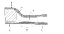
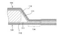
図14は、図13に示したフィルム外装電池の、ガス開放部での断面図である。図14に示すように、外装フィルム104は、熱融着樹脂層111同士を対面させて配され、熱融着部106においては、熱融着樹脂層111同士が熱融着によって一体化されている。熱融着樹脂層111の外側の層は金属層112である。この状態でフィルム外装電池の内圧が上昇すると、外装フィルム104の引き剥がし応力が熱融着部106の内縁に加わり、外装フィルム104の剥離が、熱融着樹脂層111を破壊しながら進行する。 14 is a cross-sectional view of the film-clad battery shown in FIG. 13 at the gas release portion. As shown in FIG. 14, the
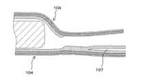
このとき、図15に示すように、熱融着樹脂層111の破壊が熱融着樹脂層111の厚さ方向の成分を有する方向に進行すると、剥離位置は、熱融着樹脂層111と金属層112との界面へ移行する。剥離位置が一旦、熱融着樹脂層111と金属層112との界面へ移行すると、それ以降は図15に太線で示すように熱融着樹脂層111と金属層112との界面に沿って剥離が進行する。最終的には、図16に示すように、剥離がガス開放部107を経由せず外装フィルム104の外端縁に達した段階で、フィルム外装電池の内部と外気が連通し、圧力が開放される。 At this time, as shown in FIG. 15, when the breakage of the heat-
このように、熱融着樹脂層と金属層との界面で剥離が進行すると、ガス開放部は安全弁として機能せず、剥離が外装フィルムの外端縁に達するまで圧力開放がなされないので、結果的に、開放圧力が高くなってしまう。また、剥離が熱融着部の突出した部分を通過した後は、熱融着樹脂層と金属層との界面での剥離の進行方向が定まらないので、圧力開放位置が大きくばらつく可能性がある。つまり、従来の圧力開放構造では、剥離の進行状況によっては、開放圧力および圧力開放位置が不安定となることがあった。 Thus, when peeling proceeds at the interface between the heat-sealing resin layer and the metal layer, the gas release part does not function as a safety valve, and pressure release is not performed until the peeling reaches the outer edge of the exterior film. As a result, the opening pressure increases. In addition, after the separation passes through the protruding part of the heat fusion part, the direction of the separation at the interface between the heat fusion resin layer and the metal layer is not fixed, so the pressure release position may vary greatly. . That is, in the conventional pressure release structure, the release pressure and the pressure release position may become unstable depending on the progress of peeling.
上述のことは、フィルム外装電池に限らず、ガスを発生する可能性のある電気デバイス要素を外装フィルムで封止したフィルム外装電気デバイスに共通の課題である。 The above is not limited to a film-clad battery, but is a problem common to a film-clad electrical device in which an electrical device element that may generate gas is sealed with a crust film.
本発明の目的は、異常時のガス発生による外装フィルムの膨張時の開放圧力および圧力開放位置を容易かつ確実に設定することのできる、フィルム外装電気デバイスおよびその製造方法を提供することにある。 An object of the present invention is to provide a film-covered electrical device and a method for manufacturing the same, which can easily and reliably set an opening pressure and a pressure-release position when the exterior film is expanded due to gas generation at the time of abnormality.
上記目的を達成するため本発明のフィルム外装電気デバイスは、電気デバイス要素と、少なくとも熱融着樹脂層を含み、該熱融着樹脂層同士を対向させて前記電気デバイス要素を包囲し、対向した前記熱融着樹脂層同士が外周部で熱融着されることによって、前記熱融着された領域を熱融着部とするとともにその内側の空間を電気デバイス要素収納部として前記電気デバイス要素を封止した外装フィルムとを有し、対向した前記外装フィルムの少なくとも一方に、前記電気デバイス要素収納部に露出する部位および外気と接する他の部位を有するように、前記熱融着部の一部を含む連続した領域で、前記熱融着樹脂層が架橋処理された架橋構造部が形成されている。 In order to achieve the above object, the film-covered electrical device of the present invention includes an electrical device element and at least a heat-sealing resin layer, and surrounds and opposes the electrical device element with the heat-sealing resin layers facing each other. The heat-sealed resin layers are heat-sealed at the outer peripheral portion, whereby the heat-fused region is used as a heat-fused portion, and the inner space is used as an electric device element storage portion to A part of the heat-sealed portion so that at least one of the facing exterior films has a portion exposed to the electrical device element storage portion and another portion in contact with the outside air. A cross-linked structure portion in which the heat-sealing resin layer is subjected to a cross-linking process is formed in a continuous region including
本発明のフィルム外装電気デバイスにおいては、対向する外装フィルムは熱融着樹脂層同士が熱融着され、これによって電気デバイス要素が封止される。熱融着によって形成された熱融着部の一部を含む領域では、対向した外装フィルムの少なくとも一方が、上記のように特定の領域で熱融着樹脂層に架橋処理が施されて架橋構造部が形成されている。熱融着部に引き剥がし応力が作用した際、架橋構造部が形成された領域では他の領域と比較して小さな力で剥離するので、フィルム外装電気デバイスの内圧上昇によって熱融着部に引き剥がし応力が作用すると、架橋構造部が形成された領域において、対向する外装フィルムの界面で優先的に剥離が進行する。その結果、剥離位置および圧力開放位置が特定され、このことから開放圧力の設定も容易になる。 In the film-covered electrical device of the present invention, the heat-seal resin layers of the facing exterior film are heat-sealed, thereby sealing the electrical device element. In a region including a part of the heat fusion part formed by heat fusion, at least one of the facing exterior films is subjected to a crosslinking treatment on the heat fusion resin layer in a specific region as described above. The part is formed. When peeling stress is applied to the heat-sealed part, the region where the cross-linked structure is formed peels off with a smaller force than other regions. When the peeling stress acts, peeling proceeds preferentially at the interface of the facing exterior film in the region where the crosslinked structure portion is formed. As a result, the separation position and the pressure release position are specified, and this makes it easy to set the release pressure.
本発明のフィルム外装電気デバイスにおいて、熱融着部を、電気デバイス要素収納部に向かって突出した突出融着部を有する形状とし、架橋構造部をこの突出融着部を含む範囲に形成することで、熱融着部に加わる引き剥がし応力は突出融着部に集中するので、架橋構造部が形成された領域での剥離の進行が促進される。また、外気と連通し且つ電池要素収納部と連通しないガス開放部を外装フィルムの外周部に有し、架橋構造部が、外気と接する他の部位としてガス開放部と接した領域を含んでいる構成とすれば、圧力開放は確実にガス開放部からなされる。この場合、ガス開放部にチューブを接続することで、圧力開放時に放出されるガスが適宜位置に導かれる。また、架橋構造部は、外装フィルムの熱融着樹脂層自身に架橋処理を施すことによって形成してもよいし、架橋処理された樹脂シートを外装フィルムに融着することによって形成してもよい。 In the film-covered electrical device of the present invention, the heat fusion part has a shape having a protrusion fusion part protruding toward the electric device element storage part, and the bridging structure part is formed in a range including the protrusion fusion part. Thus, the peeling stress applied to the heat fusion part concentrates on the protruding fusion part, so that the progress of peeling in the region where the crosslinked structure part is formed is promoted. Further, the outer peripheral portion of the exterior film has a gas release portion that communicates with the outside air but does not communicate with the battery element storage portion, and the cross-linking structure portion includes a region that is in contact with the gas release portion as another portion that contacts the outside air. With this configuration, the pressure release is surely performed from the gas release portion. In this case, by connecting a tube to the gas release portion, the gas released when the pressure is released is guided to an appropriate position. Further, the crosslinked structure portion may be formed by performing a crosslinking treatment on the heat-sealing resin layer itself of the exterior film, or may be formed by fusing the crosslinked resin sheet to the exterior film. .
本発明のフィルム外装電気デバイスの製造方法は、電気デバイス要素を、少なくとも熱融着樹脂層を含む外装フィルムで包囲し、対向した外装フィルムの外周部同士を熱融着することによって、熱融着された領域を熱融着部とするとともにその内側の空間を電気デバイス要素収納部として前記電気デバイス要素を封止するフィルム外装電気デバイスの製造方法であって、前記電気デバイス要素収納部に露出する部位と外気と接する他の部位とを有するように、前記外装フィルムの前記熱融着部とされる領域の一部を含む連続した領域で、対向する前記外装フィルムの少なくとも一方の前記熱融着樹脂層を架橋処理して架橋構造部を形成する工程と、前記架橋構造部を形成した外装フィルムで、前記熱融着樹脂層を対向させて前記電気デバイス要素を挟んで包囲する工程と、前記電気デバイス要素を包囲することによって対向した前記外装フィルムの外周部同士を熱融着し、前記電気デバイス要素を封止する工程とを有する。 The method for producing a film-clad electrical device according to the present invention includes a thermal fusion process in which an electrical device element is surrounded by an exterior film including at least a thermal fusion resin layer, and the outer peripheral portions of the opposed exterior films are thermally fused. A method for manufacturing a film-clad electrical device in which the electric device element is sealed with the region formed as a heat-sealed portion and the inner space as an electric device element accommodating portion, and is exposed to the electric device element accommodating portion The heat-sealing of at least one of the facing exterior films in a continuous region including a part of the region to be the heat-sealing portion of the exterior film so as to have a site and another site in contact with the outside air The step of forming a crosslinked structure portion by crosslinking the resin layer and the exterior film on which the crosslinked structure portion is formed with the heat sealing resin layer facing each other and the electric device A step of enclosing across the element, the outer peripheral portions of the outer film facing by surrounding the electrical device element and heat fusion, and a step of sealing said electrical device element.
このように、本発明のフィルム外装電気デバイスの製造方法は、外装フィルムを熱融着する前に、外装フィルムの所定の領域に、熱融着樹脂層を架橋処理した架橋構造部を予め形成しておく。これを用い、通常と同様に電気デバイス要素を外装フィルムで包囲し、その対面した外周部同士を熱融着することで、前述した本発明のフィルム外装電気デバイスが得られる。 As described above, in the method for producing a film-clad electrical device of the present invention, before heat-sealing the exterior film, a crosslinked structure portion obtained by crosslinking the heat-sealing resin layer is formed in a predetermined region of the exterior film in advance. Keep it. The film-covered electrical device of the present invention described above is obtained by using this and surrounding the electrical device element with the exterior film in the same manner as usual, and heat-sealing the facing outer peripheral portions.
架橋構造部は、熱融着樹脂層への電子線の照射によって形成することができる。架橋構造部が形成された領域での剥離力は、架橋構造部を形成する際の電子線の照射量によって容易に制御できる。 The crosslinked structure portion can be formed by irradiating the heat-fusion resin layer with an electron beam. The peeling force in the region where the crosslinked structure portion is formed can be easily controlled by the electron beam irradiation amount when forming the crosslinked structure portion.
本発明によれば、熱融着樹脂層の一部の領域に架橋構造部を形成し、この架橋構造部を利用して外装フィルムを熱融着することで、異常時のガス発生による外装フィルムの膨張時の開放圧力および圧力開放位置を容易かつ確実に設定することができる。 According to the present invention, a cross-linked structure portion is formed in a partial region of the heat-sealing resin layer, and the external film is heat-sealed using the cross-linked structure portion, whereby the external film caused by gas generation at the time of abnormality is obtained. It is possible to easily and reliably set the release pressure and the pressure release position during expansion.
次に、本発明の実施形態について図面を参照して説明する。 Next, embodiments of the present invention will be described with reference to the drawings.
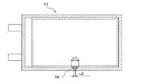
図1は、本発明の第1の実施形態によるフィルム外装電池の分解斜視図である。図2は、図1に示すフィルム外装電池の、圧力開放構造の周辺での部分平面図である。図3は、図2のA−A線断面図である。 FIG. 1 is an exploded perspective view of a film-clad battery according to a first embodiment of the present invention. FIG. 2 is a partial plan view of the film-clad battery shown in FIG. 1 around the pressure release structure. FIG. 3 is a cross-sectional view taken along line AA in FIG.
本実施形態のフィルム外装電池1は、複数の正極および複数の負極を積層した構造を有する扁平な略直方体状の電池要素2と、電池要素2の正極および負極にそれぞれ接続された正極タブ3aおよび負極タブ3bと、電池要素2を封止する2枚の外装フィルム4,5とを有する。 The film-clad battery 1 according to the present embodiment includes a flat, substantially rectangular
電池要素2は、それぞれ電極材料が両面に塗布された金属箔からなる複数の正極と複数の負極とが、セパレータを介して交互に積層された構造を有する。各正極および各負極の一辺からはそれぞれ電極材料が塗布されていない未塗布部分が突出して設けられており、正極の未塗布部分同士、および負極の未塗布部分同士がそれぞれ一括して超音波溶接されて、正極タブ3aおよび負極タブ3bと接続されている。正極および負極の超音波溶接された未塗布部分は集電部と呼ばれる。つまり、正極タブ3aおよび負極タブ3bは、それぞれ電池要素2の集電部に接続されている。 The
電池要素2を構成する正極および負極は、電極材料の未塗布部分を同じ向き揃えて重ねられている。したがって、正極タブ3aおよび負極タブ3bは、電池要素2の同じ辺に接続されている。正極タブ3aおよび負極タブ3bは、外部との電気的接続用の電極となるものであり、図2に示すように、正極タブ3aおよび負極タブ3bの先端部分は外装フィルム4,5の外側へ引き出されている。本実施形態では、フィルム外装電池1の平面形状を略長方形とし、正極タブ3aおよび負極タブ3bを、その長方形の短辺から引き出している。 The positive electrode and the negative electrode constituting the
リチウムイオン電池などの非水電解質電池の場合、一般に、正極を構成する金属箔にはアルミニウム箔が用いられ、負極を構成する金属箔には銅箔が用いられる。さらに、正極タブ3aにはアルミニウム板が用いられ、負極タブ3bにはニッケル板または銅板が用いられる。負極タブ3bを銅板で構成する場合、表面にニッケルめっきを施してもよい。 In the case of a non-aqueous electrolyte battery such as a lithium ion battery, generally, an aluminum foil is used for the metal foil constituting the positive electrode, and a copper foil is used for the metal foil constituting the negative electrode. Further, an aluminum plate is used for the
セパレータは、ポリオレフィン等の熱可塑性樹脂から作られた、マイクロポーラスフィルム(微多孔フィルム)、不織布あるいは織布など、電解液を含浸することができるシート状の部材を用いることができる。 As the separator, a sheet-like member that can be impregnated with an electrolytic solution, such as a microporous film (microporous film), a nonwoven fabric, or a woven fabric made of a thermoplastic resin such as polyolefin can be used.
外装フィルム4,5は、電池要素2をその厚み方向両側から挟んで包囲するため、電池要素2の平面寸法よりも大きな平面寸法を有するものであり、電池要素2の周囲で重なり合った対向面同士を熱融着することで、電池要素2が封止される。したがって、電池要素2の周囲は全周に亘って封止領域とされ、特にその熱融着された領域を、図面では熱融着部6として斜線で示している。一方の外装フィルム4には、電池要素2を包囲する空間である電池要素収納部を形成するために、中央領域にカップ部4aを有する。熱融着部6は、このカップ部4aの周囲全周に亘って形成されている。カップ部4aの加工は、深絞り成形によって行うことができる。本実施形態では、一方の外装フィルム4のみにカップ部4aを形成しているが、両方の外装フィルム4,5にカップ部を形成してもよいし、また、カップ部を形成せずに外装フィルム4,5の柔軟性を利用して電池要素2を包囲してもよい。 Since the
外装フィルム4,5は、ラミネートフィルムである。外装フィルム4,5を構成するラミネートフィルムとしては、柔軟性を有しており、かつ電解液が漏洩しないように熱融着によって電池要素2を封止できるものが用いられる。代表的には、図3に示されるように、熱融着性樹脂からなる熱融着樹脂層11と、金属薄膜などからなる非通気層12と、ポリエチレンテレフタレートなどのポリエステルやナイロンなどのフィルムからなる保護層13とをこの順番に積層したものが挙げられる。外装フィルム4,5は、これらのうち少なくとも熱融着層樹脂11と非通気層12とを有していればよく、保護層13は必要に応じて設けられる。電池要素2を封止するに際しては、熱融着樹脂層11を対向させて電池要素2を包囲する。 The
非通気層12を構成する金属薄膜としては、例えば、厚さが10〜100μmの、Al、Ti、Ti合金、Fe、ステンレス、Mg合金などの箔を用いることができる。熱融着樹脂層11に用いられる熱融着性樹脂については後述する。良好な熱融着を行うためには、熱融着樹脂層11の厚さは10〜200μmが好ましく、より好ましくは30〜100μmである。 As the metal thin film constituting the non-air-
封止領域の一部には、圧力開放構造が設けられている。圧力開放構造は、本実施形態では、正極タブ3aと負極タブ3bとの間に位置しており、熱融着部6の内縁の一部を電池要素側に突出させて形成した突出融着部6aと、外装フィルム4,5の外縁から突出融着部6aに向かって延び、かつ先端が突出融着部6aに達するガス開放部7とを有する。ガス開放部7は、外装フィルム4,5を熱融着せず単に外装フィルム4,5同士が向き合っているだけの外装フィルム4,5間の領域として形成され、これによりガス開放部7は外気と連通している。また、ガス開放部7は、電池要素収納部とは隔てられた位置に形成され、したがって、ガス開放部7は電池要素収納部とは連通していない。 A part of the sealing region is provided with a pressure release structure. In this embodiment, the pressure release structure is located between the
さらに、下側すなわちカップ部が形成されていない方の外装フィルム5の熱融着樹脂層11の一部には、架橋処理によって架橋構造部8が形成されている。架橋構造部8は、少なくとも突出融着部6aを含む領域に形成され、したがって、架橋構造部8は一部位が電池要素収納部に露出し、他の一部位がガス開放部7に露出している一つの連続した領域である。また、架橋構造部8が突出融着部6aを含む領域に形成されているため、突出融着部6aでは、上側の外装フィルム4の熱融着樹脂層11は下側の外装フィルム5の架橋構造部8と熱融着されている。 Further, a
なお、実際のフィルム外装電池1ではその外側からは架橋構造部8を目視することはできないが、図2では、架橋構造部8をその位置を示すものとして表している。このことは、以降の実施形態を示すフィルム外装電池の平面図においても同様である。 In the actual film-clad battery 1, the
架橋構造部8は、熱融着樹脂層11に電子線を照射することによって形成することができる。熱融着性樹脂の架橋方法としては、樹脂に架橋剤を添加する方法もあるが、電子線を利用することによって、電子線を遮蔽するマスクを用いて容易に、特定の位置のみに選択的に架橋構造部8を形成することができる。 The
このように、熱融着樹脂層11には電子線を照射することによって架橋構造部8が形成されるので、熱融着樹脂層11を構成する熱融着性樹脂としては、熱融着が可能であり、かつ電子線の照射によって架橋構造部8を形成することのできる樹脂組成物を用いることができる。このような樹脂組成物であれば、熱融着樹脂層11を構成する樹脂には、単独の樹脂、複数種の樹脂の混合物、あるいは、電子線分解型の樹脂であっても電子線反応性化合物を添加(混合・塗布等も含む。以下同様。)した樹脂組成物を用いることができる。 As described above, since the
このような樹脂組成物としては、ポリエチレン(高・中・低密度ポリエチレン、直鎖状低密度ポリエチレン)およびポリプロピレン等のポリオレフィンホモポリマー;プロピレン−エチレン共重合体、プロピレンおよび/またはエチレンとブテン−1などのα−オレフィンとの共重合体等のポリオレフィン共重合体;エチレン−酢酸ビニル共重合体(EVA)、エチレン−エチルアクリレート共重合体(EEA)、エチレン−メチルアクリレート共重合体(EMA)、エチレン−グリシジメタクリレート共重合体(EGMA)等の、変成ポリオレフィン等の−(CH2−CHX)−なる繰り返し単位(Xは、H、CH3等の置換基)を有する樹脂を挙げることができる。Examples of such a resin composition include polyolefin homopolymers such as polyethylene (high / medium / low density polyethylene, linear low density polyethylene) and polypropylene; propylene-ethylene copolymer, propylene and / or ethylene and butene-1 Polyolefin copolymers such as copolymers with α-olefins such as: ethylene-vinyl acetate copolymer (EVA), ethylene-ethyl acrylate copolymer (EEA), ethylene-methyl acrylate copolymer (EMA), Examples thereof include resins having a repeating unit of — (CH2 —CHX) — such as a modified polyolefin, such as an ethylene-glycidyl methacrylate copolymer (EGMA) (where X is a substituent such as H or CH3 ). .
また、ポリイソブチレン、ポリメタアクリレート、ポリフッ化ビニリデン等の電子線分解型の樹脂であっても、以下に示すような電子線反応性化合物を添加すれば、熱融着樹脂層11を構成する樹脂として使用可能である。 Moreover, even if it is electron beam decomposition-type resin, such as polyisobutylene, polymethacrylate, and polyvinylidene fluoride, if the electron beam reactive compound as shown below is added, resin which comprises the heat-
電子線反応性化合物としては、電子線の照射により反応する化合物であれば特に限定されないが、多官能であって架橋構造を形成しうるものが好ましい。例えば、トリエチレングリコールジ(メタ)アクリレート、トリメチロールプロパントリ(メタ)アクリレート、ペンタエリスリトールテトラアクリレート、ジペンタエリスリトールヘキサアクリレート、ペンタエリスリトールトリアクリレートヘキサメチレンジイソシアネートウレタンポリマー等の多官能アクリル系化合物;メチル(メタ)アクリレート、メトキシポリエチレングリコール(メタ)アクリレート等の単官能アクリル系化合物;多官能アクリル系化合物と単官能アクリル系化合物との混合物;3,4−エポキシシクロヘキシルメチル−3',4'−エポキシシクロヘキサンカルボキシレート、1,4−(6−メチル−3,4−エポキシシクロヘキシルメチルカルボキシレート)ブタン等の脂環式エポキシ化合物;ビニルピロリドン、ビニルアセテート、ビニルピリジン、スチレン等のビニル化合物等を用いることができる。これらの電子線反応化合物は、熱融着性樹脂層の全体に混入されていてもよいし、表面に塗布されていてもよい。 The electron beam reactive compound is not particularly limited as long as it is a compound that reacts upon irradiation with an electron beam, but is preferably a polyfunctional compound capable of forming a crosslinked structure. For example, polyfunctional acrylic compounds such as triethylene glycol di (meth) acrylate, trimethylolpropane tri (meth) acrylate, pentaerythritol tetraacrylate, dipentaerythritol hexaacrylate, pentaerythritol triacrylate hexamethylene diisocyanate urethane polymer; Monofunctional acrylic compounds such as meth) acrylate and methoxypolyethylene glycol (meth) acrylate; mixtures of polyfunctional acrylic compounds and monofunctional acrylic compounds; 3,4-epoxycyclohexylmethyl-3 ′, 4′-epoxycyclohexane Alicyclic epoxy compounds such as carboxylate and 1,4- (6-methyl-3,4-epoxycyclohexylmethylcarboxylate) butane; vinylpyrrole Emissions, vinyl acetate, vinyl pyridine, can be used vinyl compounds such as styrene. These electron beam reaction compounds may be mixed in the whole heat-fusible resin layer, and may be apply | coated to the surface.
熱融着樹脂層11への電子線の照射は、電池要素2の封止工程の前、具体的には、外装フィルム4,5で電池要素2を包囲する前に、外装フィルム5単体に対して、架橋構造部8を形成しない領域を電子線遮蔽部材でマスクして行う。電子線遮蔽部材としては、架橋構造部8を形成しない領域へ電子線が照射されないようにすることができるものであれば任意の材料を用いることができ、例えば、アルミニウム、鉄、鉛、チタン、銅等の金属材料、あるいはガラス材が挙げられる。これらの中でも、所望の形状への加工や成形が容易であるという観点から、アルミニウムや鉄などの金属材料が好ましい。 Irradiation of the electron beam to the heat-sealing
次に、本実施形態のフィルム外装電池1の製造方法の一例を説明する。 Next, an example of the manufacturing method of the film-clad battery 1 of this embodiment is demonstrated.
まず、2枚の外装フィルム4,5のうち一方の外装フィルム5に、上述のようにして所定の領域に電子線を照射することによって架橋構造部8を形成する。 First, the
次いで、予め用意しておいた、正極タブ3aおよび負極タブ3bを接続した電池要素2を、上記の外装フィルム4,5で挟んで包囲する。この際、外装フィルム4,5は、熱融着樹脂層11同士を対向させた向きとする。その後、外装フィルム4,5の、電池要素2の周囲で対向している領域を、熱融着ヘッド(不図示)で加圧および加熱して熱融着部6を形成し、これによって電池要素2を封止する。熱融着の際、熱融着ヘッドとして、熱融着部6の形状に対応した加圧面を有する熱融着ヘッドを用いれば、突出融着部6aおよびガス開放部7を形成するための特別な工程は不要となる。また、突出融着部6aを形成する位置が外装フィルム5の架橋構造部8の位置と一致するように、外装フィルム4,5と熱融着ヘッドとが相対的に位置決めされる。 Next, the
電池要素2の封止は、例えば、外装フィルム4,5の3辺を一括または各辺ごとに先に熱融着して、外装フィルム4,5を1辺が開放した袋状に形成しておき、その袋状となった外装フィルム4,5の開放している残りの1辺から電解液を注入し、その後、残りの1辺を熱融着することによって行うことができる。また、残りの1辺の熱融着を減圧雰囲気中(減圧チャンバ内)で行えば、封止後のフィルム外装電池1を大気圧雰囲気中に戻すことによって、外装フィルム4,5は大気圧によって電池要素2に押し付けられ、外装フィルム4,5を電池要素2に密着させることができる。 The
以上のように構成されたフィルム外装電池1によれば、使用中に規格範囲外の電圧が印加されたり、一時的に高温になったりすることなどによって電池要素2からガスが発生すると、フィルム外装電池1の内圧が上昇する。内圧が上昇すると、外装フィルム4,5内の電池要素2を包囲する空間である電池要素収納部はドーム状に膨らもうとし、熱融着部6の内縁には外装フィルム4,5の引き剥がし応力が作用する。 According to the film-clad battery 1 configured as described above, when gas is generated from the
熱融着部6には前述した突出融着部6aが形成されているので、引き剥がし応力は、この突出融着部6aに集中し、外装フィルム4,5の剥離は突出融着部6aで優先的に進行する。突出融着部6aは、図3に明確に示すように、外装フィルム5の架橋構造部8と外装フィルム4の熱融着樹脂層11とが熱融着された領域である。架橋構造部8は、熱融着樹脂層11と比べて高温で軟化しにくく、両者を熱融着しても架橋構造部8と熱融着樹脂層11とは完全には一体化せず、架橋構造部8と熱融着樹脂層11との間に境界が存在している。ここで、「高温で軟化しにくい」とは、例えば樹脂を一定の応力で加圧しながら昇温させたときの温度−ひずみ特性、いわゆるクリープ曲線において、横軸を温度としたときにそのクリープ曲線の傾きが小さくなることをいう。 Since the protruding
突出融着部6aでは架橋構造部8と熱融着樹脂層11とが熱融着された構造となっているため、外装フィルム4,5の剥離は、外装フィルム5の架橋構造部8と外装フィルム4の熱融着樹脂層11との境界に沿って進行する。剥離の進行に伴い、図4に示すように、突出融着部6aにおいては、外装フィルム4,5は外装フィルム4の架橋されていない熱融着樹脂層11と外装フィルム5の架橋構造部8との境界で分離し、電池要素収納部とガス開放部7とが連通する。電池要素収納部とガス開放部7とが連通することにより、電池要素収納部内のガスはガス開放部7を介してフィルム外装電池1の外部へ放出され、電池要素収納部の圧力が開放される。このように、架橋構造部8によって外装フィルム4,5の剥離界面が規定されるので、ガスの開放圧力が安定しており、かつ、圧力開放がガス開放部7で確実になされる、信頼性の高いフィルム外装電池1が提供される。 Since the protruding
以下に、外装フィルム4,5のうちの一方に、架橋構造部8を形成することによって、外装フィルム4,5の界面で剥離が進行する原理について説明する。 Below, the principle by which peeling progresses in the interface of the
架橋された樹脂層(以下、架橋樹脂層という)と架橋されていない樹脂層(以下、非架橋樹脂層)とを熱融着した場合、架橋樹脂層と非架橋樹脂層との融着界面では次のようなことが起こる。架橋樹脂層においては、架橋された高分子鎖は流動することができないため、非架橋樹脂層中の高分子鎖との間で相互に溶融し合って一体化することは起こりにくい。ただし、架橋樹脂層であってもその架橋度によっては、架橋された高分子鎖のマトリクスの隙間あるいは内部に、架橋されていない高分子鎖も存在する。そのような架橋されていないフリーな高分子鎖が集まっている微小部分では、高分子鎖は融点以上の温度で溶融・流動することができる。 When a cross-linked resin layer (hereinafter referred to as a cross-linked resin layer) and a non-cross-linked resin layer (hereinafter referred to as a non-cross-linked resin layer) are heat-sealed, at the fusion interface between the cross-linked resin layer and the non-cross-linked resin layer, The following happens: In the cross-linked resin layer, the cross-linked polymer chain cannot flow, and therefore, it is difficult for the polymer chains in the non-cross-linked resin layer to melt and integrate with each other. However, even in the crosslinked resin layer, depending on the degree of crosslinking, there are polymer chains that are not crosslinked in the gaps or inside the matrix of the crosslinked polymer chains. In such a minute portion where free non-crosslinked polymer chains are gathered, the polymer chains can melt and flow at a temperature higher than the melting point.
したがって、上記微小部分が非架橋樹脂層との融着界面に接しているような場合、互いに接している架橋樹脂層および非架橋樹脂層を融点以上の温度に加熱すると、融着界面を通じて各樹脂層間で高分子鎖が相互に流動し合う。そして加熱された各樹脂層が冷却されて固化したときには、架橋樹脂層中の架橋されていない高分子鎖と、架橋樹脂層中の高分子鎖とが混ざり合った凝集体あるいは結晶体が、融着界面を通じて各樹脂層間で連続一体化した状態で形成されることが可能となる。 Therefore, when the minute portion is in contact with the fusion interface with the non-crosslinked resin layer, when the crosslinked resin layer and the non-crosslinked resin layer in contact with each other are heated to a temperature equal to or higher than the melting point, each resin passes through the fusion interface. Polymer chains flow between each other between layers. When each heated resin layer is cooled and solidified, aggregates or crystals in which the polymer chains in the crosslinked resin layer and the polymer chains in the crosslinked resin layer are mixed are melted. It can be formed in a state of continuous integration between the resin layers through the adhesion interface.
以上のように、架橋樹脂層と非架橋樹脂層とを熱融着した場合は、融着界面では、両樹脂層同士の融着に寄与するのは架橋樹脂層中の架橋されていない高分子鎖であり、架橋樹脂層中の架橋された高分子鎖は非架橋樹脂層と連続一体化はしていない。このような、連続一体化していない部分が存在するのは両樹脂層の融着界面であり、したがって、両樹脂層に引き剥がし応力が作用すると、両樹脂層の融着界面、すなわち外装フィルム4,5の界面で剥離が進行する。 As described above, when the cross-linked resin layer and the non-cross-linked resin layer are heat-sealed, it is the non-cross-linked polymer in the cross-linked resin layer that contributes to the fusing between the two resin layers at the fusing interface. The crosslinked polymer chain in the crosslinked resin layer is not continuously integrated with the non-crosslinked resin layer. Such a portion that is not continuously integrated exists in the fusion interface between the two resin layers. Therefore, when peeling stress acts on both resin layers, the fusion interface between the two resin layers, that is, the
ここで、架橋樹脂層の架橋度を変化させると、架橋されていないフリーな高分子鎖が集まっている上記微小部分の占める割合が変化する。その結果、架橋樹脂層と非架橋樹脂層とを熱融着させたとき、融着界面を通じて各樹脂層間で連続一体化した上記凝集体あるいは結晶体の割合が変化する。具体的には、架橋樹脂層の架橋度を低くすると、上記微小部分の占める割合が高くなり、各樹脂層間で連続一体化した凝集体あるいは結晶体の割合が高くなる。各樹脂層間で連続一体化した凝集体あるいは結晶体の割合が高ければ高いほど、各樹脂層の融着強度は高くなる。架橋樹脂層の架橋度は、電子線の照射量を変化させることなどにより制御可能であるから、電子線の照射量を制御することにより各樹脂層の融着強度も自由に制御できることになる。 Here, when the degree of cross-linking of the cross-linked resin layer is changed, the proportion of the minute portion in which free polymer chains that are not cross-linked are gathered changes. As a result, when the crosslinked resin layer and the non-crosslinked resin layer are heat-sealed, the ratio of the aggregates or crystals continuously integrated between the resin layers through the fusion interface changes. Specifically, when the degree of cross-linking of the cross-linked resin layer is lowered, the proportion of the fine portions increases, and the proportion of aggregates or crystals continuously integrated between the resin layers increases. The higher the ratio of aggregates or crystals continuously integrated between the resin layers, the higher the fusion strength of the resin layers. Since the degree of cross-linking of the cross-linked resin layer can be controlled by changing the amount of electron beam irradiation, the fusion strength of each resin layer can be freely controlled by controlling the amount of electron beam irradiation.
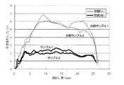
融着強度は、別の言い方をすれば剥離強度を意味する。すなわち、融着強度が高ければそれだけ剥離しにくくなり、剥離強度も高くなる。本発明者は、架橋構造層の有無による剥離強度の違いを調べるため、以下のような引き剥がし試験を行った。 In other words, the fusing strength means peel strength. That is, the higher the fusion strength, the more difficult it is to peel, and the higher the peel strength. The present inventor conducted the following peeling test in order to examine the difference in peel strength depending on the presence or absence of the crosslinked structure layer.
まず、対向させる外装フィルムのうち一方の側に架橋構造層を形成し、架橋構造層と非架橋構造層とを対向させて外装フィルムの一部を10mm幅で熱融着した。比較のため、架橋構造層を形成していない外装フィルムを用い、同様に、外装フィルムの一部を10mmの熱融着幅で熱融着した。次いで、熱融着したそれぞれの外装フィルムについて、外装フィルムの熱融着した部分を、熱融着の幅方向と直角な方向に、熱融着していない部分も含めて同じ長さに切り出し、それぞれサンプルおよび比較サンプルとした。 First, a crosslinked structure layer was formed on one side of the facing exterior film, and a part of the exterior film was heat-sealed with a width of 10 mm with the crosslinked structure layer and the non-crosslinked structure layer facing each other. For comparison, an exterior film having no crosslinked structure layer was used, and similarly, a part of the exterior film was thermally fused with a thermal fusion width of 10 mm. Next, for each of the heat-sealed exterior films, the heat-sealed part of the exterior film is cut out in the direction perpendicular to the width direction of the heat-sealing, including the part that is not thermally fused, to the same length, Samples and comparative samples were used respectively.
これらサンプルおよび比較サンプルをそれぞれ2つずつ作製し、熱融着されていない部分をチャックして、熱融着された部分を180°方向に引き剥がしていき、そのときに作用する力を測定した。その測定結果を図5に示す。なお、図5において、横軸は引き剥がし長さを示しているが、これはチャック間の距離を意味している。したがって、この引き剥がし長さは、実際には外装フィルムの延びも含まれており、熱融着部が完全に引き剥がされた際のチャック間の距離は約25mmとなっている。図5から明らかなように、サンプル1,2は、比較サンプル1,2と比較して全般的に小さな引き剥がし力で剥離している。すなわち、対向する外装フィルムの界面に架橋構造層が存在することで、剥離強度が小さくなる。 Two each of these samples and comparative samples were prepared, the non-heat-sealed part was chucked, the heat-fused part was peeled off in the 180 ° direction, and the force acting at that time was measured. . The measurement results are shown in FIG. In FIG. 5, the horizontal axis indicates the peeling length, which means the distance between chucks. Therefore, the peeling length actually includes the extension of the exterior film, and the distance between the chucks when the heat-sealed portion is completely peeled is about 25 mm. As is clear from FIG. 5, the
本実施形態でのガスの開放圧力は、突出融着部6aにおける外装フィルム4,5の剥離強度に依存する。融着強度は、上述したように架橋構造部8を形成する際の電子線の照射量に依存する。電子線の照射量が大きければ、電子線を照射した熱融着樹脂層11の架橋度が高くなり、突出融着部6aでの外装フィルム4,5の剥離強度は小さくなる傾向にある。剥離強度を小さくすることによって、より低い圧力で圧力開放がなされる。すなわち、熱融着樹脂層11の架橋度を適宜調整することによって、開放圧力を任意に設定することができる。 The gas release pressure in the present embodiment depends on the peel strength of the
フィルム外装電池1においては、好ましい設計上の開放圧力は、大気圧からの上昇分として0.05MPa〜1MPaであり、より好ましくは0.1MPa〜0.2MPaである。開放圧力が低すぎると、一時的に大電流が流れたり一次的に高温になったりしたときなどの軽微なトラブルでも開放してしまい、フィルム外装電池1が作動しなくなるという不具合を招く。一方、開放圧力が高すぎると、ガス開放部7まで剥離が進行する前に他の部位で開放し、意図しない方向へガスが噴出してしまう危険性が増大する。 In the film-clad battery 1, a preferable design opening pressure is 0.05 MPa to 1 MPa, more preferably 0.1 MPa to 0.2 MPa as an increase from atmospheric pressure. If the opening pressure is too low, even a minor trouble such as when a large current flows temporarily or when the temperature becomes temporarily high can be released, leading to a problem that the film-clad battery 1 becomes inoperable. On the other hand, if the release pressure is too high, the risk of gas being released in an unintended direction is increased at other sites before the
上述した実施形態では、1つの圧力開放構造をフィルム外装電池1の短辺の、特に正極タブ3aおよび負極タブ3bが引き出された辺に配置した例を示したが、圧力開放構造の数、および配置する位置はフィルム外装電池1の使用目的や使用条件等に応じて適宜変更することができる。図6に、その一例を本発明の第2の実施形態として示す。 In the above-described embodiment, an example in which one pressure release structure is arranged on the short side of the film-clad battery 1, particularly on the side from which the
図6に示すフィルム外装電池21は、その長辺に圧力開放構造を有する。本実施形態においても、正極タブ23aおよび負極タブ23bはフィルム外装電池21の短辺から引き出されており、したがって本実施形態では、圧力開放構造は正極タブ23aおよび負極タブ23bが引き出された辺とは異なる辺に設けられている。なお、電池要素(不図示)はその厚み方向両側から2枚の外装フィルム24に挟まれるように包囲され、外装フィルム24の周縁部を全周にわたって熱融着することによって、正極タブ23aおよび負極タブ23bが引き出された状態で封止されている。電池要素の構成および外装フィルム24の層構成は第1の実施形態と同様であるので、その詳細な説明は省略する。 The film-clad
圧力開放構造は、外装フィルム24の熱融着によって形成された熱融着部26の内縁の一部を電池要素側に突出させて形成した突出融着部26aと、外装フィルム24の外縁から突出融着部26aに向かって延び、かつ先端が突出融着部26aに達するガス開放部27とを有する。ガス開放部27は、外装フィルム24を熱融着せず単に外装フィルム24同士が向き合っているだけの領域として形成され、これによりガス開放部27は外気と連通している。 The pressure release structure has a protruding
圧力開放構造を正極タブ23aおよび負極タブ23bが引き出された辺に設ける場合は、正極タブ23aおよび負極タブ23bが引き出された辺においては電池要素と熱融着部26との間に集電部のためのスペースが必要となるため、フィルム外装電池21の外形寸法を変更することなく熱融着部26に突出融着部を設けることができる。しかし、圧力開放構造を正極タブ23aおよび負極タブ23bが引き出されていない辺に設ける場合は、その辺においては電池要素と熱融着部26との間に上記のようなスペースはないため、熱融着部26に単純に突出融着部26aを付加しようとすると、フィルム外装電池21の外形寸法が大きくなってしまう。 In the case where the pressure release structure is provided on the side where the
そこで本実施形態では、外装フィルム24を部分的に外側に張り出した形状とし、この張り出した部分で電池要素収納部に連通した入り江状の領域が形成されるように熱融着部26を形成するとともに、入り江状の領域に突出融着部26aを形成している。突出融着部26aの両側は外装フィルム24が熱融着されていない非融着部24aとして形成される。このように、電池要素収納部に連通した入り江状の領域を形成し、この領域に突出融着部26aを形成することで、フィルム外装電池21の外形寸法の増大を最小限に抑えつつ、応力集中部としての機能を有する突出融着部26aを形成することができる。 Therefore, in the present embodiment, the
さらに、本実施形態においても、2枚の外装フィルム24のうち1枚には、電子線の照射により熱融着樹脂層に架橋構造部28が形成されている。 Furthermore, also in this embodiment, the cross-linking structure portion 28 is formed on the heat-sealing resin layer on one of the two
架橋構造部28は、突出融着部26aを含む領域に形成され、その一部が電池要素収納部およびガス開放部27に露出している。したがって、電池要素収納部の内圧上昇に伴う外装フィルム24の剥離は、第1の実施形態と同様に、架橋構造部8ともう一方の外装フィルムの熱融着樹脂層との境界に沿って進行するので、ガスの開放圧力が安定しており、かつ圧力開放がガス開放部27で確実になされる、信頼性の高いフィルム外装電池21が提供される。 The bridging structure portion 28 is formed in a region including the protruding fused
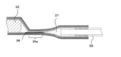
図7は、本発明の第3の実施形態によるフィルム外装電池の平面図である。図8は、図7のB−B線断面図である。 FIG. 7 is a plan view of a film-clad battery according to the third embodiment of the present invention. 8 is a cross-sectional view taken along line BB in FIG.
本実施形態のフィルム外装電池31は、第2の実施形態と比較して、ガス開放部37にチューブ39を接続した点が異なる。その他、圧力開放構造として、熱融着部36の一部に応力集中部として突出融着部36aが形成されていること、外装フィルム34が熱融着されていない空間であるガス開放部37が、突出融着部36aに先端部を臨ませて形成されていること、突出融着部36aを含む領域において2枚の外装フィルム34のうち一方の熱融着樹脂層に架橋構造部38を形成すること等は、第2の実施形態と同様である。 The film-clad
チューブ39は、一端部がガス開放部37に気密に接続され、開放した他端部は、電池要素32から発生したガスが放出されても影響のない適宜位置に引き回されている。チューブ39の他端部は開放しているので、ガス開放部37はチューブ39を介して外気と連通している。電池要素32からガスが発生すると、電池要素32を収納する空間である電池要素収納部の内圧が上昇し、それに伴い、突出融着部36aで外装フィルム34が剥離する。この剥離によって、電池要素収納部からガス開放部37にガスが導入され、導入されたガスは、チューブ39を通って、チューブ39の開放端から放出される。 One end of the
このように、ガス開放部37にチューブ39を接続することによって、ガスの放出位置を任意に設定することができる。また、ガスの放出位置をチューブ39によって任意に設定できるので、圧力開放構造の位置も任意に設定することができる。本実施形態は、フィルム外装電池31の周囲にガスの影響を受け易い部材や機器が存在しており、ガス開放部37からガスを直接放出させるのが好ましくない場合に特に有効である。チューブ39の開放端をフィルム外装電池31から離した位置に設置すれば、フィルム外装電池31から離れた位置にガスを放出させることができる。チューブ39は、外装フィルム34の剥離界面を規定し電池要素収納部とガス開放部37とが確実を連通させることができてはじめて、有効に機能する。 Thus, by connecting the
チューブ39は、可撓性を有する部材で構成するのが好ましい。可撓性を有する部材でチューブ39を構成することで、チューブ39の引き回しを容易に行うことができ、また、フィルム外装電池31の設置後も、ガスの放出位置を自由に変更することができる。ガス開放部37へのチューブ39の接続は、2枚の外装フィルム34の間にチューブ39の端部を挟み、その状態で外装フィルム34の外縁部をチューブ39の外周面に接着することによって行うことができる。外装フィルム34とチューブ39との接着方法は、チューブ39を気密に接続できれば特に限定されず、接着剤によって接着することもできるし、チューブ39が熱可塑性樹脂からなるものであれば熱融着によって接着することもできる。特に、チューブ39を外装フィルム34の熱融着樹脂層を構成する熱融着性樹脂と同種の樹脂で構成すれば、熱融着によってチューブ39を接続することができる。チューブ39の熱融着は、ガス開放部37を形成する際にチューブ39を挿入するための口部を残して外装フィルム34を熱融着し、次いで、口部を介してガス開放部37内にチューブ39の端部を挿入し、その状態でチューブ39を外装フィルム34に熱融着することによって行ってもよい。あるいは、電池要素32の封止の際に、チューブ39を外装フィルム34間に挟まれる所定の位置に設置しておき、外装フィルム34への熱融着部36の形成と同時にチューブ39を接続することができる。 The
本実施形態では、第2の実施形態にチューブ39を適用した例を示したが、第1の実施形態にも同様に適用することができる。 In this embodiment, the example which applied the
上述した各実施形態は何れも、外装フィルムの剥離を優先的に進行させる応力集中部を熱融着部に設け、その部分に架橋構造部を形成した例を示した。架橋構造部は、前述したように、他の領域と比べて高温で軟化しにくい領域であり、結果的に架橋構造部が形成された領域自身も他の領域と比べて剥離強度が小さくなっている。したがって、架橋構造部を形成するだけで十分に剥離位置を規定できる場合は、応力集中部を設けず単に熱融着部の一部に架橋構造部を形成した構成とすることもできる。その幾つかの例を以下に示す。 Each embodiment mentioned above showed the example which provided the stress concentration part which advances peeling of an exterior film preferentially in a heat-fusion part, and formed the bridge | crosslinking structure part in the part. As described above, the crosslinked structure portion is a region that is hard to be softened at a high temperature as compared with other regions. As a result, the region where the crosslinked structure portion is formed itself has a lower peel strength than the other regions. Yes. Therefore, in the case where the peeling position can be sufficiently defined only by forming the crosslinked structure portion, a configuration in which the crosslinked structure portion is formed in a part of the heat fusion portion without providing the stress concentration portion can be adopted. Some examples are shown below.
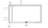
図9は、本発明の第4の実施形態によるフィルム外装電池の平面図である。本実施形態のフィルム外装電池41は、矩形状の外装フィルム44を用いており、その周縁部に、全周にわたって一定の幅で熱融着部46が形成され、これによって電池要素(不図示)が封止されている。そして、熱融着部46の一部には、内縁を、電池要素を収納する電池要素収納部に露出させ、かつ、外縁を熱融着部46の外縁と一致させて、熱融着樹脂層に架橋構造部48が形成されている。つまり、架橋構造部48は、電池要素収納部に露出した部位以外の部位を外気と連通させて形成されている。 FIG. 9 is a plan view of a film-clad battery according to a fourth embodiment of the present invention. The film-clad
本実施形態のように、応力集中部を熱融着部46に設けない構造としても、架橋構造部48が形成された領域は熱融着部46の他の領域と比べて剥離強度が小さくなっており、フィルム外装電池41の内圧上昇に伴う外装フィルム44の剥離は、架橋構造部48が形成された領域で優先的に進行する。そして、剥離が架橋構造部48の外縁まで達することによって、電池要素収納部と外気とが連通し、架橋構造部48が形成された領域の外縁からガスが放出されて圧力解放がなされる。 Even if the stress concentration portion is not provided in the
架橋構造部48の形状やサイズは、架橋構造部48が、一部が電池要素収納部に露出し、かつ、電池要素収納部に露出していない他の部位が外気と連通するような形状やサイズであれば特に限定されない。図9では矩形状に架橋構造部48を形成した例を示したが、例えば図10に示すフィルム外装電池51のように、台形形状に架橋構造部58を形成してもよい。図10には、内縁の長さL1が外縁の長さL2よりも長く、電池要素収納部側の縁から外側に向かって寸法が小さくなるように形成された架橋構造部58が示される。架橋構造部58をこのように形成することで、架橋構造部58が外装フィルム54の剥離の進行に合わせた形状となるので、剥離をよりスムーズに進行させることができる。 The shape and size of the bridging
図11に、応力集中部を有しない圧力開放構造の他の例を示す。図11に示すフィルム外装電池61は、図10に示した例に、第3の実施形態で示したチューブ69を適用したものである。すなわち、外装フィルム64には、その架橋構造部68が形成された領域に先端部を臨ませて、外装フィルム64同士を熱融着しないことによってガス開放部67が形成され、このガス開放部67にチューブ69が気密に接続されている。このように、架橋構造部68がガス開放部67およびチューブ69を介して外気と連通する構造としても、安定した圧力で、かつ特定の位置からガスを放出させることができる。外装フィルム64の外縁からガスを放出しても構わない場合は、第1の実施形態のように、チューブ69を設けずガス開放部67が外気と直接連通する構成としてもよい。 FIG. 11 shows another example of a pressure release structure that does not have a stress concentration portion. A film-clad
また、上述した例では外装フィルム自身に架橋構造部を形成した例を示したが、架橋構造部は、外装フィルム自身に形成するのではなく、架橋させた樹脂シートを対向する外装フィルム間に挟むこと、言い換えれば、対向する外装フィルムの一方に、架橋させた樹脂シートを融着させることによって形成してもよい。その例の、熱融着部近傍での断面図を図12に示す。図12に示す例では、熱融着部76の一部において、2枚の外装フィルム74,75間に、架橋処理された樹脂シート78が挟み込まれている。樹脂シート78は、一部位が、電池要素72を収納している電池要素収納部に露出し、他の一部位がガス開放部77に露出しており、この条件を満たしていれば、そのサイズや形状等は特に限定されず、他の構造も含めて、上述した各例と同様に配置することができる。 Moreover, although the example which formed the crosslinked structure part in exterior film itself was shown in the example mentioned above, a crosslinked structure part is not formed in exterior film itself, but sandwiches the crosslinked resin sheet between opposing exterior films. In other words, it may be formed by fusing a cross-linked resin sheet to one of the facing exterior films. A cross-sectional view of the example in the vicinity of the heat fusion part is shown in FIG. In the example illustrated in FIG. 12, a
樹脂シート78は、対向する2枚の外装フィルム74,75のいずれか一方に、外装フィルム74,85同士を熱融着する前に、予め熱融着されることによって設けられている。樹脂シート78を構成する樹脂は、電池要素72を封止するのに必要な最低限の融着強度を確保するために、外装フィルム74,75の熱融着樹脂層74a,75aと同種の樹脂を用いるのが好ましい。また、樹脂シート78の形態としては、フィルム状であってもよいし、メッシュ状であってもよい。メッシュ状とすれば、熱融着によって溶融した熱融着樹脂層74a,75aが樹脂シート78の網目中に浸透することによって生じるアンカー効果による、必要な融着強度の確保が期待できる。もちろん、樹脂シート78の形態にかかわらず、樹脂シート78の架橋度を適宜調整することによって、外装フィルム74,75との融着強度を任意に制御することもできる。熱融着部76の剥離は、一方の外装フィルム74と樹脂シート78との界面、またはもう一方の外装フィルム75と樹脂シート78の界面のいずれかで生じるが、いずれの場合でも、樹脂シート78が介在した領域で剥離が進行する。 The
このように、樹脂シート78によって架橋構造部を形成しても、上述した各例と同様の効果が得られる。特に本例においては、架橋構造部を外装フィルム74,75とは別の樹脂シート78で形成するので、外装フィルム74,75に架橋構造部を形成しているか否かの区別が容易に行え、製造工程中での部品管理が容易になるとともに、外装フィルム74,75(特に熱融着樹脂層74a,75a)の材料の選択の幅が広がる。 As described above, even when the crosslinked structure portion is formed by the
以上、本発明について代表的な幾つかの例を挙げて説明したが、本発明はこれらに限定されるものではなく、本発明の技術的思想の範囲内で適宜変更されうることは明らかである。 The present invention has been described above with some typical examples. However, the present invention is not limited to these examples, and it is obvious that the present invention can be appropriately modified within the scope of the technical idea of the present invention. .
例えば、上述した例では2枚の外装フィルムのうち1枚に架橋構造部を形成した例を示したが、電池要素を封止するのに十分な接着力が得られれば双方の外装フィルムに架橋構造部を形成してもよい。その場合の、各外装フィルムへの電子線の照射量は等しくてもよいし互いに異なっていてもよい。この構成を図12に示した例に適用する場合は、各外装フィルムにそれぞれ、架橋処理された樹脂シートを融着することになる。 For example, in the above-described example, an example in which a crosslinked structure portion is formed on one of the two exterior films is shown. If sufficient adhesive strength is obtained to seal the battery element, both exterior films are crosslinked. A structure part may be formed. In that case, the irradiation amount of the electron beam to each exterior film may be equal, or may be different from each other. When this configuration is applied to the example shown in FIG. 12, a resin sheet that has been subjected to a crosslinking treatment is fused to each exterior film.
また、上述した例では2枚の外装フィルムで電池要素をその厚み方向両側から挟んで周囲の4辺を熱融着した例を示したが、その他にも、1枚の外装フィルムを2つ折りにして電池要素を挟み、開放している3辺を熱融着することによって電池要素を封止してもよい。 In the above-described example, the battery element is sandwiched from two sides in the thickness direction with two exterior films, and the surrounding four sides are heat-sealed. In addition, one exterior film is folded in two. The battery element may be sealed by sandwiching the battery element and thermally fusing the three open sides.
電池要素の構造について、上述した例では複数の正極および複数の負極を交互に積層した積層型を示したが、正極、負極およびセパレータを帯状に形成し、セパレータを挟んで正極および負極を重ね合わせ、これを捲回した後、扁平状に圧縮することによって、正極と負極とを交互に配置させた捲回型の電池要素であってもよい。 Regarding the structure of the battery element, the above example shows a stacked type in which a plurality of positive electrodes and a plurality of negative electrodes are alternately stacked. However, the positive electrode, the negative electrode, and the separator are formed in a strip shape, and the positive electrode and the negative electrode are stacked with the separator interposed therebetween. After winding this, it may be a wound battery element in which the positive electrode and the negative electrode are alternately arranged by compressing in a flat shape.
また、電池要素としては、正極、負極および電解質を含む物であれば、通常の電池に用いられる任意の電池要素が適用可能である。一般的なリチウムイオン二次電池における電池要素は、リチウム・マンガン複合酸化物、コバルト酸リチウム等の正極活物質をアルミニウム箔などの両面に塗布した正極板と、リチウムをドープ・脱ドープ可能な炭素材料を銅箔などの両面に塗布した負極板とを、セパレータを介して対向させ、それにリチウム塩を含む電解液を含浸させて形成される。電池要素としては、この他に、ニッケル水素電池、ニッケルカドミウム電池、リチウムメタル一次電池あるいは二次電池、リチウムポリマー電池等、他の種類の化学電池の電池要素が挙げられる。さらに、本発明は、電気二重層キャパシタなどのキャパシタや電解コンデンサなどに例示されるキャパシタ要素のような、電気エネルギーを内部に蓄積し化学反応または物理反応でガスを発生し得る電気デバイスを外装フィルムで封止した電気デバイスに適用可能である。 As the battery element, any battery element used for a normal battery can be applied as long as it includes a positive electrode, a negative electrode, and an electrolyte. Battery elements in a typical lithium ion secondary battery include a positive electrode plate in which a positive electrode active material such as lithium-manganese composite oxide and lithium cobaltate is applied on both sides of an aluminum foil, etc., and carbon that can be doped / undoped with lithium. A negative electrode plate coated with a material on both sides of a copper foil or the like is opposed to each other with a separator interposed between them and impregnated with an electrolytic solution containing a lithium salt. Other battery elements include battery elements of other types of chemical batteries such as nickel metal hydride batteries, nickel cadmium batteries, lithium metal primary batteries or secondary batteries, lithium polymer batteries, and the like. Furthermore, the present invention provides an exterior film as an electrical device capable of accumulating electrical energy and generating gas by chemical reaction or physical reaction, such as a capacitor element exemplified by a capacitor such as an electric double layer capacitor and an electrolytic capacitor. It is applicable to an electric device sealed with
さらに、上述した各例では正極タブと負極タブとをフィルム外装電池の同じ辺から引き出した例を示したが、これらは互いに異なる辺、例えば対向する2辺、あるいは隣り合う2辺から引き出されてもよい。 Furthermore, in each of the above-described examples, the positive electrode tab and the negative electrode tab are drawn from the same side of the film-clad battery, but these are drawn from different sides, for example, two opposite sides or two adjacent sides. Also good.
1,21,31,41,51,61 フィルム外装電池
2,32,72 電池要素
3a,23a 正極タブ
3b,23b 負極タブ
4,5,24,34,44,54,64,74,75 外装フィルム
4a カップ部
6,26,36,46,76 熱融着部
6a,26a,36a 突出融着部
7,27,37,67,77 ガス開放部
8,28,38,48,58,68 架橋構造部
11 熱融着樹脂層
12 非通気層
13 保護層
24a 非融着部
39,69 チューブ
78 樹脂シート1, 21, 31, 41, 51, 61
Claims (18)
Translated fromJapanese少なくとも熱融着樹脂層を含み、該熱融着樹脂層同士を対向させて前記電気デバイス要素を包囲し、対向した前記熱融着樹脂層同士が外周部で熱融着されることによって、前記熱融着された領域を熱融着部とするとともにその内側の空間を電気デバイス要素収納部として前記電気デバイス要素を封止した外装フィルムとを有し、
前記熱融着部は、前記電気デバイス要素収納部に向かって突出した突出融着部を有し、
対向した前記外装フィルムの少なくとも一方に、前記電気デバイス要素収納部に露出する部位および外気と接する他の部位を有するように、前記突出融着部を含む連続した領域で、架橋処理された樹脂からなる架橋構造部が形成されているフィルム外装電気デバイス。An electrical device element;
Including at least a heat-sealing resin layer, surrounding the electric device elements with the heat-sealing resin layers facing each other, and the heat-sealing resin layers facing each other being heat-sealed at an outer peripheral portion, The heat-sealed region is used as a heat-sealed portion, and the outer space having the inner space as an electric device element storage portion and sealing the electric device element,
The thermal fusion part has a protruding fusion part protruding toward the electrical device element storage part,
From a cross-linked resin in a continuous region including theprotruding fusion part so that at least one of the facing exterior films has a part exposed to the electrical device element storage part and another part in contact with outside air A film-clad electrical device in which a cross-linked structure is formed.
前記電気デバイス要素収納部に露出する部位と外気と接する他の部位とを有するように、前記外装フィルムの前記突出融着部を含む連続した領域で、対向する前記外装フィルムの少なくとも一方に、架橋処理された樹脂からなる架橋構造部を形成する工程と、
前記架橋構造部を形成した外装フィルムで、前記熱融着樹脂層を対向させて前記電気デバイス要素を挟んで包囲する工程と、
前記電気デバイス要素を包囲することによって対向した前記外装フィルムの外周部同士を熱融着し、前記電気デバイス要素を封止する工程とを有するフィルム外装電気デバイスの製造方法。The electrical device element is surrounded by an exterior film including at least a heat-sealing resin layer, and the outer peripheral portions of the facing exterior films are heat-sealed to form a heat-sealed region as a heat-sealing portion.A film-covered electrical device having an inner space as an electrical device element storage portion and sealing the electrical device element, and theheat fusion portion having a protruding fusion portion protruding toward the electrical device element storage portion A manufacturing method comprising:
Cross-linking to at least one of the facing exterior films in a continuous region including theprotruding fused portion of the exterior film so as to have a portion exposed to the electrical device element storage portion and another portion in contact with outside air Forming a crosslinked structure portion made of the treated resin;
A step of enclosing the electric device element with the heat sealing resin layer facing the exterior film in which the crosslinked structure portion is formed;
A method of manufacturing a film-covered electrical device, comprising: heat-sealing outer peripheral portions of the exterior films facing each other by surrounding the electrical device element, and sealing the electrical device element.
Priority Applications (9)
| Application Number | Priority Date | Filing Date | Title |
|---|---|---|---|
| JP2004234524AJP4232038B2 (en) | 2004-08-11 | 2004-08-11 | Film-clad electrical device and method for manufacturing the same |
| CN2005800273065ACN101010817B (en) | 2004-08-11 | 2005-08-05 | Film-encapsulated electrical device and manufacturing method thereof |
| KR1020077004313AKR100887792B1 (en) | 2004-08-11 | 2005-08-05 | Film-enclosed electric device and production method therefor |
| US11/573,538US8283061B2 (en) | 2004-08-11 | 2005-08-05 | Film-encased electric device and production method therefor |
| CN2013100549546ACN103187177A (en) | 2004-08-11 | 2005-08-05 | Film-enclosed electric device |
| DE602005024287TDE602005024287D1 (en) | 2004-08-11 | 2005-08-05 | FILM-CONNECTED ELECTRICAL EQUIPMENT AND METHOD OF MANUFACTURING THEREOF |
| PCT/JP2005/014428WO2006016535A1 (en) | 2004-08-11 | 2005-08-05 | Film-enclosed electric device and production method therefor |
| EP05768917AEP1793436B1 (en) | 2004-08-11 | 2005-08-05 | Film-enclosed electric device and production method therefor |
| AT05768917TATE485604T1 (en) | 2004-08-11 | 2005-08-05 | FILM-INCLUDED ELECTRICAL DEVICE AND METHOD OF PRODUCTION THEREOF |
Applications Claiming Priority (1)
| Application Number | Priority Date | Filing Date | Title |
|---|---|---|---|
| JP2004234524AJP4232038B2 (en) | 2004-08-11 | 2004-08-11 | Film-clad electrical device and method for manufacturing the same |
Related Child Applications (1)
| Application Number | Title | Priority Date | Filing Date |
|---|---|---|---|
| JP2008199491ADivisionJP4900339B2 (en) | 2008-08-01 | 2008-08-01 | Film-clad electrical device and method for manufacturing the same |
Publications (2)
| Publication Number | Publication Date |
|---|---|
| JP2006054099A JP2006054099A (en) | 2006-02-23 |
| JP4232038B2true JP4232038B2 (en) | 2009-03-04 |
Family
ID=35839305
Family Applications (1)
| Application Number | Title | Priority Date | Filing Date |
|---|---|---|---|
| JP2004234524AExpired - Fee RelatedJP4232038B2 (en) | 2004-08-11 | 2004-08-11 | Film-clad electrical device and method for manufacturing the same |
Country Status (8)
| Country | Link |
|---|---|
| US (1) | US8283061B2 (en) |
| EP (1) | EP1793436B1 (en) |
| JP (1) | JP4232038B2 (en) |
| KR (1) | KR100887792B1 (en) |
| CN (2) | CN103187177A (en) |
| AT (1) | ATE485604T1 (en) |
| DE (1) | DE602005024287D1 (en) |
| WO (1) | WO2006016535A1 (en) |
Families Citing this family (49)
| Publication number | Priority date | Publication date | Assignee | Title |
|---|---|---|---|---|
| JP4232038B2 (en) | 2004-08-11 | 2009-03-04 | 日本電気株式会社 | Film-clad electrical device and method for manufacturing the same |
| US8062780B2 (en) | 2005-03-17 | 2011-11-22 | Nec Corporation | Film-covered electric device and method of manufacturing same |
| JP4968423B2 (en)* | 2005-05-30 | 2012-07-04 | 大日本印刷株式会社 | Lithium battery exterior |
| JP4649294B2 (en)* | 2005-08-30 | 2011-03-09 | 株式会社東芝 | Nonaqueous electrolyte battery and portable information device |
| JP5161421B2 (en)* | 2005-10-19 | 2013-03-13 | 株式会社東芝 | Non-aqueous electrolyte battery |
| EP1978550A4 (en) | 2005-12-28 | 2009-07-22 | Nec Corp | FIELD EFFECT TRANSISTOR, AND MULTILAYER EPITAXIAL FILM FOR USE IN FIELD EFFECT TRANSISTOR PREPARATION |
| US8071231B2 (en)* | 2006-08-28 | 2011-12-06 | Lg Chem, Ltd. | Secondary battery including one-way exhaust valve |
| JP4925427B2 (en)* | 2006-09-27 | 2012-04-25 | 日立マクセルエナジー株式会社 | Laminated non-aqueous secondary battery |
| JP2008091583A (en)* | 2006-09-30 | 2008-04-17 | Nippon Chemicon Corp | Laminated film sealing type capacitor |
| US8722241B2 (en) | 2007-02-21 | 2014-05-13 | Nec Corporation | Packaged battery, stacked battery assembly, and film-covered battery |
| KR100944987B1 (en)* | 2007-12-14 | 2010-03-02 | 주식회사 엘지화학 | Secondary battery including novel sealing part structure |
| US8257848B2 (en) | 2009-01-12 | 2012-09-04 | A123 Systems, Inc. | Safety venting mechanism with tearing tooth structure for batteries |
| JP5059890B2 (en) | 2009-03-31 | 2012-10-31 | Jmエナジー株式会社 | Laminate exterior power storage device |
| JP2010267593A (en)* | 2009-05-18 | 2010-11-25 | Fuji Heavy Ind Ltd | Electricity storage device |
| JP5364548B2 (en)* | 2009-12-03 | 2013-12-11 | Udトラックス株式会社 | Module power storage unit and manufacturing method thereof |
| US9240578B2 (en) | 2010-03-09 | 2016-01-19 | Samsung Sdi Co., Ltd. | Secondary battery |
| JP5035397B2 (en) | 2010-07-28 | 2012-09-26 | Tdk株式会社 | Electrochemical devices |
| CN102623749A (en)* | 2011-01-26 | 2012-08-01 | 深圳市崧鼎实业有限公司 | Electrical core packaging method and apparatus thereof |
| KR101531271B1 (en)* | 2011-11-08 | 2015-06-25 | 에스케이이노베이션 주식회사 | Battery cell, and secondary battery |
| WO2013105763A1 (en)* | 2012-01-09 | 2013-07-18 | 주식회사 희성화학 | Aluminum pouch film for secondary battery, packaging material including same, secondary battery including same, and method for manufacturing aluminum pouch film for secondary battery |
| JP5423825B2 (en)* | 2012-02-06 | 2014-02-19 | 大日本印刷株式会社 | Lithium battery exterior |
| KR20140013132A (en)* | 2012-07-09 | 2014-02-05 | 에스케이이노베이션 주식회사 | Secondary battery |
| JP6152260B2 (en)* | 2012-11-01 | 2017-06-21 | 昭和電工パッケージング株式会社 | Battery exterior material and battery |
| JP6426895B2 (en) | 2013-05-31 | 2018-11-21 | 昭和電工パッケージング株式会社 | Battery exterior material and battery |
| CN103383995B (en)* | 2013-07-29 | 2016-01-20 | 宁波慧通新能源科技有限公司 | Anti-explosion battery |
| CN105723558B (en)* | 2013-11-11 | 2019-04-09 | 日产自动车株式会社 | Manufacturing method of thin film encapsulated battery |
| US20150187508A1 (en)* | 2013-12-26 | 2015-07-02 | Minwax Electronic Enterprise Ltd. | Electrolytic Capacitor |
| JP2015153971A (en)* | 2014-02-18 | 2015-08-24 | ローム株式会社 | capacitor device |
| PL225943B1 (en)* | 2014-09-05 | 2017-06-30 | Krawczyk Zenon P P H U Zenex | Power capacitor with protective device |
| JP6634671B2 (en)* | 2014-12-10 | 2020-01-22 | 日本電気株式会社 | Secondary battery, electric vehicle, power storage system, and manufacturing method |
| KR102071894B1 (en)* | 2015-11-12 | 2020-01-31 | 주식회사 엘지화학 | Battery Case Comprising Sheet Released Part and Battery Cell Comprising the Same |
| CN205406573U (en)* | 2016-03-02 | 2016-07-27 | 宁德时代新能源科技股份有限公司 | Soft packet of secondary cell casing |
| CN109155206A (en) | 2016-05-20 | 2019-01-04 | 阿维科斯公司 | Nonaqueous Electrolytes for Supercapacitors |
| JP7061971B2 (en)* | 2016-05-20 | 2022-05-02 | キョーセラ・エイブイエックス・コンポーネンツ・コーポレーション | Multicell ultracapacitor |
| JP6644650B2 (en)* | 2016-06-29 | 2020-02-12 | 太陽誘電株式会社 | Power storage cell, exterior film and power storage module |
| CN106606844B (en)* | 2016-09-27 | 2019-08-20 | 简极科技有限公司 | A kind of more air bag intelligent spheres and its production technology |
| CN106606845A (en)* | 2016-09-27 | 2017-05-03 | 简极科技有限公司 | A double-air bag intelligent ball and a production process therefor |
| KR102347901B1 (en)* | 2017-10-17 | 2022-01-06 | 주식회사 엘지에너지솔루션 | Pouch-Type Battery Case Having Structure to Prevent Crack and Method for Preparing the Same |
| KR102019682B1 (en)* | 2017-12-08 | 2019-09-09 | 주식회사 엘지화학 | Secondary Battery Case Having Vent Filled with Thermoplastic Resin |
| CN110311062B (en)* | 2018-03-27 | 2021-09-21 | 比亚迪股份有限公司 | A safety cover and battery package for tray |
| CN110789200A (en)* | 2018-04-04 | 2020-02-14 | 徐雄剑 | Water-blocking flame-retardant composite film for lithium battery packaging and preparation method thereof |
| CN109004282B (en)* | 2018-07-25 | 2023-11-03 | 柔电(武汉)科技有限公司 | Sealing head for ultrathin soft-package lithium battery, sealing head assembly, packaging device and packaging method |
| DE102018125842A1 (en)* | 2018-10-18 | 2020-04-23 | Bayerische Motoren Werke Aktiengesellschaft | Cell housing for a battery cell of a high-voltage battery of a motor vehicle, battery cell, high-voltage battery and motor vehicle |
| KR102793092B1 (en)* | 2019-11-13 | 2025-04-08 | 주식회사 엘지에너지솔루션 | The Secondary Battery And The Sealing Block |
| WO2022213379A1 (en)* | 2021-04-09 | 2022-10-13 | 宁德新能源科技有限公司 | Battery cell and electrical device |
| EP4224612A4 (en)* | 2021-04-15 | 2025-01-29 | LG Energy Solution, Ltd. | SECONDARY BATTERY |
| CN215896547U (en)* | 2021-08-17 | 2022-02-22 | 宁德新能源科技有限公司 | Packaging shell, battery and electric equipment |
| KR102779018B1 (en)* | 2021-11-23 | 2025-03-12 | 한국과학기술연구원 | Multi-layer film for lead-tab of lithium secondary battery and preparation method thereof |
| KR20230081208A (en)* | 2021-11-30 | 2023-06-07 | 에스케이온 주식회사 | Battery cell |
Family Cites Families (25)
| Publication number | Priority date | Publication date | Assignee | Title |
|---|---|---|---|---|
| US4613550A (en)* | 1985-08-30 | 1986-09-23 | Gnb Incorporated | Venting system for electric storage batteries |
| JP3063924B2 (en) | 1991-06-28 | 2000-07-12 | 株式会社ユアサコーポレーション | Thin battery |
| JP3293287B2 (en)* | 1993-12-07 | 2002-06-17 | 松下電器産業株式会社 | Square sealed alkaline storage battery and its unit battery |
| JPH09115498A (en) | 1995-10-19 | 1997-05-02 | Sanyo Electric Co Ltd | Sealed storage battery |
| JPH1055792A (en) | 1996-08-12 | 1998-02-24 | Yuasa Corp | Thin battery |
| JP3554155B2 (en) | 1997-07-24 | 2004-08-18 | 東芝電池株式会社 | Lithium secondary battery and method of manufacturing the same |
| JP3638765B2 (en)* | 1997-09-05 | 2005-04-13 | 株式会社リコー | Non-aqueous flat battery |
| JP2000235845A (en) | 1998-12-16 | 2000-08-29 | Japan Storage Battery Co Ltd | Thin battery |
| JP2000306565A (en)* | 1999-02-15 | 2000-11-02 | Konno Kogyosho:Kk | Safety mechanism of sealed type battery |
| EP1047137A3 (en)* | 1999-04-19 | 2002-02-27 | Japan Storage Battery Co., Ltd. | Battery sealed in battery case of resin film |
| JP3460805B2 (en)* | 1999-06-24 | 2003-10-27 | 日本電気株式会社 | Battery manufacturing method |
| JP3837004B2 (en) | 2000-03-17 | 2006-10-25 | Tdk株式会社 | Sheet type battery |
| JP4862211B2 (en) | 2000-08-08 | 2012-01-25 | 株式会社Gsユアサ | Sealed secondary battery |
| FR2819036B1 (en)* | 2001-01-04 | 2004-01-16 | Cit Alcatel | VALVE AND ELECTROCHEMICAL GENERATOR COMPRISING SUCH A VALVE |
| JP2002319379A (en)* | 2001-04-20 | 2002-10-31 | Dainippon Printing Co Ltd | Battery packaging material and battery using the same |
| JP2002324526A (en) | 2001-04-24 | 2002-11-08 | Toyota Motor Corp | Battery covering structure, method, and battery capable of preventing air from entering during abnormal heating |
| JP2002362617A (en) | 2001-06-01 | 2002-12-18 | Toppan Printing Co Ltd | Package |
| JP4953527B2 (en) | 2001-07-27 | 2012-06-13 | パナソニック株式会社 | battery |
| JP2003132868A (en) | 2001-10-25 | 2003-05-09 | Mitsubishi Cable Ind Ltd | Sheet-like battery |
| KR20030066895A (en) | 2002-02-05 | 2003-08-14 | 삼성에스디아이 주식회사 | Secondary battery |
| JP4604441B2 (en) | 2002-07-18 | 2011-01-05 | 日本電気株式会社 | Film-clad battery and manufacturing method thereof |
| JP2004213963A (en)* | 2002-12-27 | 2004-07-29 | Nissan Motor Co Ltd | Thin battery |
| JP3859645B2 (en) | 2004-01-16 | 2006-12-20 | Necラミリオンエナジー株式会社 | Film exterior electrical device |
| JP4232038B2 (en) | 2004-08-11 | 2009-03-04 | 日本電気株式会社 | Film-clad electrical device and method for manufacturing the same |
| US8062780B2 (en) | 2005-03-17 | 2011-11-22 | Nec Corporation | Film-covered electric device and method of manufacturing same |
- 2004
- 2004-08-11JPJP2004234524Apatent/JP4232038B2/ennot_activeExpired - Fee Related
- 2005
- 2005-08-05WOPCT/JP2005/014428patent/WO2006016535A1/enactiveApplication Filing
- 2005-08-05DEDE602005024287Tpatent/DE602005024287D1/ennot_activeExpired - Lifetime
- 2005-08-05CNCN2013100549546Apatent/CN103187177A/enactivePending
- 2005-08-05USUS11/573,538patent/US8283061B2/ennot_activeExpired - Fee Related
- 2005-08-05EPEP05768917Apatent/EP1793436B1/ennot_activeExpired - Lifetime
- 2005-08-05CNCN2005800273065Apatent/CN101010817B/ennot_activeExpired - Fee Related
- 2005-08-05KRKR1020077004313Apatent/KR100887792B1/ennot_activeExpired - Fee Related
- 2005-08-05ATAT05768917Tpatent/ATE485604T1/ennot_activeIP Right Cessation
Also Published As
| Publication number | Publication date |
|---|---|
| CN101010817B (en) | 2013-03-27 |
| US8283061B2 (en) | 2012-10-09 |
| EP1793436A4 (en) | 2009-04-15 |
| ATE485604T1 (en) | 2010-11-15 |
| JP2006054099A (en) | 2006-02-23 |
| CN103187177A (en) | 2013-07-03 |
| EP1793436B1 (en) | 2010-10-20 |
| US20080233468A1 (en) | 2008-09-25 |
| KR100887792B1 (en) | 2009-03-09 |
| WO2006016535A1 (en) | 2006-02-16 |
| KR20070038168A (en) | 2007-04-09 |
| CN101010817A (en) | 2007-08-01 |
| DE602005024287D1 (en) | 2010-12-02 |
| EP1793436A1 (en) | 2007-06-06 |
Similar Documents
| Publication | Publication Date | Title |
|---|---|---|
| JP4232038B2 (en) | Film-clad electrical device and method for manufacturing the same | |
| JP4900339B2 (en) | Film-clad electrical device and method for manufacturing the same | |
| JP5010467B2 (en) | Film-clad electrical device and method for manufacturing the same | |
| JP3859645B2 (en) | Film exterior electrical device | |
| JP5692264B2 (en) | Film-clad battery, battery mounting body, and assembled battery | |
| JP4876915B2 (en) | Film exterior electrical device | |
| KR100708023B1 (en) | Film-packaged electric device and its manufacturing method | |
| KR100515833B1 (en) | Jelly-roll type electrode assembly and secondary battery applying the same | |
| JP2003242952A (en) | Rechargeable battery | |
| KR100365769B1 (en) | Method for production of battery | |
| WO2006067979A1 (en) | Case for film jacket electric device | |
| JP5114018B2 (en) | Film-clad electrical device and manufacturing method thereof | |
| WO2017047473A1 (en) | Battery | |
| EP4535538A1 (en) | Battery cell, battery module comprising battery cell, and sealing apparatus | |
| KR20220014566A (en) | Pouch-type battery with CPP tape coated by absorbent | |
| KR20240001973U (en) | Battery cell | |
| KR20250063255A (en) | Secondary battery and manufacturing method for secondary battery |
Legal Events
| Date | Code | Title | Description |
|---|---|---|---|
| A711 | Notification of change in applicant | Free format text:JAPANESE INTERMEDIATE CODE: A711 Effective date:20070111 | |
| A131 | Notification of reasons for refusal | Free format text:JAPANESE INTERMEDIATE CODE: A131 Effective date:20080604 | |
| A521 | Request for written amendment filed | Free format text:JAPANESE INTERMEDIATE CODE: A523 Effective date:20080801 | |
| TRDD | Decision of grant or rejection written | ||
| A01 | Written decision to grant a patent or to grant a registration (utility model) | Free format text:JAPANESE INTERMEDIATE CODE: A01 Effective date:20081112 | |
| A01 | Written decision to grant a patent or to grant a registration (utility model) | Free format text:JAPANESE INTERMEDIATE CODE: A01 | |
| A61 | First payment of annual fees (during grant procedure) | Free format text:JAPANESE INTERMEDIATE CODE: A61 Effective date:20081125 | |
| FPAY | Renewal fee payment (event date is renewal date of database) | Free format text:PAYMENT UNTIL: 20111219 Year of fee payment:3 | |
| R150 | Certificate of patent or registration of utility model | Ref document number:4232038 Country of ref document:JP Free format text:JAPANESE INTERMEDIATE CODE: R150 Free format text:JAPANESE INTERMEDIATE CODE: R150 | |
| FPAY | Renewal fee payment (event date is renewal date of database) | Free format text:PAYMENT UNTIL: 20111219 Year of fee payment:3 | |
| FPAY | Renewal fee payment (event date is renewal date of database) | Free format text:PAYMENT UNTIL: 20121219 Year of fee payment:4 | |
| FPAY | Renewal fee payment (event date is renewal date of database) | Free format text:PAYMENT UNTIL: 20121219 Year of fee payment:4 | |
| FPAY | Renewal fee payment (event date is renewal date of database) | Free format text:PAYMENT UNTIL: 20131219 Year of fee payment:5 | |
| LAPS | Cancellation because of no payment of annual fees |