JP4230775B2 - Shielded surgical scalpel - Google Patents
Shielded surgical scalpelDownload PDFInfo
- Publication number
- JP4230775B2 JP4230775B2JP2002576821AJP2002576821AJP4230775B2JP 4230775 B2JP4230775 B2JP 4230775B2JP 2002576821 AJP2002576821 AJP 2002576821AJP 2002576821 AJP2002576821 AJP 2002576821AJP 4230775 B2JP4230775 B2JP 4230775B2
- Authority
- JP
- Japan
- Prior art keywords
- shield
- shielded
- proximal
- distal
- handle
- Prior art date
- Legal status (The legal status is an assumption and is not a legal conclusion. Google has not performed a legal analysis and makes no representation as to the accuracy of the status listed.)
- Expired - Lifetime
Links
Images


Classifications
- A—HUMAN NECESSITIES
- A61—MEDICAL OR VETERINARY SCIENCE; HYGIENE
- A61B—DIAGNOSIS; SURGERY; IDENTIFICATION
- A61B17/00—Surgical instruments, devices or methods
- A61B17/32—Surgical cutting instruments
- A61B17/3209—Incision instruments
- A61B17/3211—Surgical scalpels, knives; Accessories therefor
- A61B17/3213—Surgical scalpels, knives; Accessories therefor with detachable blades
- A—HUMAN NECESSITIES
- A61—MEDICAL OR VETERINARY SCIENCE; HYGIENE
- A61B—DIAGNOSIS; SURGERY; IDENTIFICATION
- A61B17/00—Surgical instruments, devices or methods
- A61B17/32—Surgical cutting instruments
- A61B17/3209—Incision instruments
- A61B17/3211—Surgical scalpels, knives; Accessories therefor
- A61B2017/32113—Surgical scalpels, knives; Accessories therefor with extendable or retractable guard or blade
Landscapes
- Health & Medical Sciences (AREA)
- Life Sciences & Earth Sciences (AREA)
- Surgery (AREA)
- Heart & Thoracic Surgery (AREA)
- Engineering & Computer Science (AREA)
- Biomedical Technology (AREA)
- Nuclear Medicine, Radiotherapy & Molecular Imaging (AREA)
- Medical Informatics (AREA)
- Molecular Biology (AREA)
- Animal Behavior & Ethology (AREA)
- General Health & Medical Sciences (AREA)
- Public Health (AREA)
- Veterinary Medicine (AREA)
- Surgical Instruments (AREA)
- Materials For Medical Uses (AREA)
Abstract
Description
Translated fromJapanese本発明は、外科用の切断器具に関する。 The present invention relates to a surgical cutting instrument.
従来の外科用器具、たとえば外科用メスには、医療施設内で、外科医、看護師および他の医療従事者に害を与えるという重大な潜在性がある。手術室では、様々な外科用器具が、人から人へと素早く手で渡される。このような露出した鋭い縁部を有する器具を迅速に取り扱うと、不測の切創または刺創をまねくことがある。また、不注意で外科用手袋に穴が開いて手袋の完全性を喪失させ、さらに外科医、看護師または他の医療従事者の感染の危険性を高めることもある。このような不測の切創または刺創は、感染者から他の人に体液の交換によって移ることのある後天性免疫不全症候群(AIDS:Acquired Immunosuppressive Deficiency Syndrome)やC型肝炎といった今日では不治かつ/または致死的な疾病が出現するという理由で特に問題である。 Conventional surgical instruments, such as surgical scalpels, have significant potential for harming surgeons, nurses, and other medical personnel within medical facilities. In the operating room, various surgical instruments are quickly handed from person to person. Quick handling of instruments with such exposed sharp edges can lead to unexpected cuts or stab wounds. It can also inadvertently puncture surgical gloves, losing the integrity of the gloves, and further increasing the risk of infection for surgeons, nurses or other health care workers. Such unexpected cuts or stab wounds are incurable today and / or acquired immunesuppressive deficiency syndrome (AIDS) and hepatitis C, which can be transferred from one infected person to another by exchanging body fluids. Or is particularly problematic because of the emergence of fatal diseases.
これまで、不注意な切断または穿刺を防ぐ試みがなされた結果、外科用メスで使用される刃のための様々なタイプのシールド機構が開発された。たとえば、格納式の刃を備えた設計や、格納式の内部/外部シールドを備えた設計もあった。数多くの様々の設計が開発されたが、これらの設計の多くには重大な欠点があった。一部の設計には、操作に2本の手を必要とし、さもなければ操作が困難で、または故障しやすいものもあった。 To date, attempts have been made to prevent inadvertent cutting or puncturing, and as a result, various types of shield mechanisms have been developed for blades used in surgical scalpels. For example, there were designs with retractable blades and designs with retractable inner / outer shields. Many different designs have been developed, but many of these designs have significant drawbacks. Some designs required two hands for operation, otherwise operation was difficult or prone to failure.
したがって、本発明の目的は、シールド付外科用メスを提供することにある。 Accordingly, an object of the present invention is to provide a shielded surgical knife.
本発明の他の目的は、操作に片手のみを必要とする操作が単純なシールド付外科用メスを提供することにある。 Another object of the present invention is to provide a shielded scalpel with a simple operation requiring only one hand for operation.
本発明の他の目的は、故障しにくいシールド付外科用メスを提供することにある。 Another object of the present invention is to provide a shielded surgical knife which is less prone to failure.
本発明のシールド付外科用メスは、長手軸を画定し、肩部によって隔てられた基端部と末端部とを有する細長いハンドルを含む。刃は、細長いハンドルの末端部に固定して取り付けられている。基端と末端側端とを備えたシールドは、細長いハンドル上にしっかりと装着されており、細長いハンドルの末端部に沿って長手軸方向に移動可能である。シールドは、該シールドが刃への不注意な接近を実質的に妨げる末端側位置と、シールドが使用のために刃を露出させる基端側位置との間で移動可能である。細長いハンドルおよびシールドの設計は、臨床医に、シールド付外科用メスの適正な操作について直感的に認識できる指示を与えるようなものである。それに加えて、細長いハンドル上にある矢印が、刃を保護または露出させるために臨床医がシールドを移動させなければならない方向を臨床医に視覚的に指示する。さらに、シールドを末端側位置でロックすると、細長いハンドルの末端部上にあるロック指示線が、シールドの基端と概ね一直線になる。これは、シールドが適正にロックされ、刃が保護されたことを臨床医に視覚的に示す。 The shielded scalpel of the present invention includes an elongated handle defining a longitudinal axis and having a proximal end and a distal end separated by a shoulder. The blade is fixedly attached to the distal end of the elongated handle. A shield with a proximal end and a distal end is securely mounted on the elongated handle and is movable longitudinally along the distal end of the elongated handle. The shield is movable between a distal position where the shield substantially prevents inadvertent access to the blade and a proximal position where the shield exposes the blade for use. The elongated handle and shield design is such as to give the clinician an intuitively recognizable instruction on the proper operation of the shielded scalpel. In addition, an arrow on the elongated handle visually indicates to the clinician the direction in which the clinician must move the shield to protect or expose the blade. Further, when the shield is locked in the distal position, the lock indicator line on the distal end of the elongated handle is generally aligned with the proximal end of the shield. This visually indicates to the clinician that the shield is properly locked and the blade is protected.
シールドは、細長いハンドルの末端部に形成されたスロット内に配置された少なくとも1つの内向きボスを有する上向きに偏倚された片持ち式の指作動部を含む。スロットは、基端側の上向き端部と末端側の上向き端部とを備え、概ね長手方向に延びている。この上向き端部は、細長いハンドルに対するシールドの最基端側および最末端側の行程を画定する。細長いハンドルの基端側および末端側の上向き端部と、シールドの内向きボスとは、それらが協働してシールドを場合に応じて末端側または基端側位置で堅固に保持するように構成される。シールドの上向きに偏倚された片持ち式の指作動部に下向きの圧力をかけ、ボスを基端側または末端側の上向き端部から出して、スロットの長手方向部分と概ね一直線になるように移動させることによって、末端側位置および基端側位置からシールドを解放することができる。解放した後は、シールドを場合に応じて末端側または基端側に移動させて、刃を保護または露出させることができる。 The shield includes an upwardly biased cantilevered finger actuator having at least one inwardly directed boss disposed in a slot formed at the distal end of the elongated handle. The slot has a proximal-side upward end and a distal-side upward end and extends generally in the longitudinal direction. This upward end defines the most proximal and distal most stroke of the shield relative to the elongated handle. The proximal and distal upward ends of the elongated handle and the inward boss of the shield are configured so that they cooperate to hold the shield firmly in the distal or proximal position, as the case may be Is done. Apply downward pressure to the upwardly biased cantilevered finger actuating portion of the shield and move the boss out of the proximal or distal upward end so that it is generally aligned with the longitudinal portion of the slot By doing so, the shield can be released from the distal position and the proximal position. Once released, the shield can be moved distally or proximally as appropriate to protect or expose the blade.
また、シールドは、細長いハンドルの末端部の表面に係合する内向きのラグを含む。このラグは、確実に、シールドを細長いハンドル上にぴったりと嵌合させ、特にシールドが基端側位置にあるときに、細長いハンドルに対するシールドの望ましくない横方向の移動を妨げる。 The shield also includes an inward lug that engages the surface of the distal end of the elongated handle. This lug ensures that the shield fits snugly on the elongated handle and prevents unwanted lateral movement of the shield relative to the elongated handle, particularly when the shield is in the proximal position.
シールドおよび細長いハンドルは、シールドが基端側位置にあるときに、臨床医の手袋が、シールドの基端と、細長いハンドルの基端部と末端部とを隔てている肩部との間に挟まれないように協働する。スロットは、細長いハンドルに対するシールドの行程長さを画定する。スロットの場所およびその長さは、シールドが基端側位置にあるときに、シールドの基端と細長いハンドル上の肩部との間に確実に隙間ができるように選択されると好ましい。 When the shield and elongated handle are in the proximal position, the clinician's gloves are sandwiched between the proximal end of the shield and the shoulder that separates the proximal and distal ends of the elongated handle. Collaborate so as not to The slot defines the stroke length of the shield for the elongated handle. The location of the slot and its length are preferably selected to ensure a gap between the proximal end of the shield and the shoulder on the elongated handle when the shield is in the proximal position.
シールドは、それが基端側位置にあるとき、使用時に刃の妨げにならないように構成される。具体的には、臨床医が刃を患者に対して浅い角度で使用できるように、シールドの末端側底縁部が、標準的な刃の形状に一致する曲線をもって形成される。 The shield is configured so that it does not interfere with the blade when in use when it is in the proximal position. Specifically, the distal bottom edge of the shield is formed with a curve that matches the shape of a standard blade so that the clinician can use the blade at a shallow angle to the patient.
最後に、本発明のシールド付外科用メスの組立てを容易にするために、シールドの片側に1つのバンプが配置されるようにして1対のバンプをシールドの外表面上に形成する。これらのバンプによって、製造プロセスで使用されるシールドをあるステーションから別のステーションへと運ぶコンベヤレール上に、シールドを乗せることができる。 Finally, to facilitate assembly of the shielded surgical scalpel of the present invention, a pair of bumps are formed on the outer surface of the shield such that one bump is disposed on one side of the shield. These bumps allow the shield to be placed on a conveyor rail that carries the shield used in the manufacturing process from one station to another.
前述および他の目的ならびに利点は、添付図面および以下の詳細な説明を考慮すれば明らかになる。本発明の好ましい実施形態は、図面に示されている。図面において、同一の参照番号は、複数の図面全体を通して同様の要素を表す。 The foregoing and other objects and advantages will become apparent in view of the accompanying drawings and the following detailed description. Preferred embodiments of the invention are illustrated in the drawings. In the drawings, like reference numbers represent like elements throughout the several views.
本明細書で使用する「基端側」という用語は、通常使用時に装置を使用する臨床医に最も近く、関連して装置が使用されている患者から最も遠い本発明のシールド付外科用メス上の場所を指す。反対に、「末端側」という用語は、通常使用時に装置を使用する臨床医から最も遠く、関連して装置が使用されている患者に最も近い、本発明のシールド付外科用メス上の場所を指す。 As used herein, the term “proximal” refers to the shielded scalpel of the present invention that is closest to the clinician using the device during normal use and is furthest from the patient to whom the device is being used. Point to the location. Conversely, the term “distal” refers to the location on the shielded scalpel of the present invention that is furthest from the clinician using the device during normal use and is closest to the patient to whom the device is being used. Point to.
本明細書で使用する「上部」、「上方」または「上向き」という用語は、通常使用時に、装置の長手軸から径方向に離れ、患者の皮膚から離れた本発明のシールド付外科用メス上の場所を示す。反対に、本明細書で使用する「底部」、「下方」または「下向き」という用語は、通常使用時に、装置の長手軸から径方向に離れ、患者の皮膚の方を向いた本発明のシールド付外科用メス上の場所を示す。 As used herein, the terms “upper”, “upper” or “upward” refer to the shielded surgical scalpel of the present invention radially away from the longitudinal axis of the device and away from the patient's skin during normal use. Indicates the location. In contrast, as used herein, the terms “bottom”, “downward” or “downward” refer to the shield of the present invention in normal use, radially away from the longitudinal axis of the device and toward the patient's skin. Shows location on surgical scalpel.
本明細書で使用する「内」または「内向き」という用語は、通常使用時に、装置の内側に向かう本発明のシールド付外科用メスに対する場所を示す。反対に、本明細書で使用する「外」または「外向き」という用語は、通常使用時に、装置の外側に向かう本発明のシールド付外科用メスに対する場所を示す。 As used herein, the term “inward” or “inward” refers to a location relative to the shielded scalpel of the present invention toward the inside of the device during normal use. Conversely, as used herein, the term “out” or “outward” refers to a location for the shielded surgical scalpel of the present invention that faces the outside of the device during normal use.
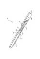
本発明のシールド付外科用メス10の好ましい実施形態は、概ね図面に示されている。シールド付外科用メス10は、長手軸を画定する細長いハンドル20を含み、肩部22によって隔てられた基端部と末端部とを有する。ハンドル20の基端部には、外科処置の際に臨床医を支援するスケール27を含ませることができる。ハンドル20の末端部には、以下に示すように、刃30を露出または保護するためにシールドをハンドル20に対して移動すべき方向を臨床医に視覚的に指示するための矢印28を含ませることができる。図示されるように、矢印28は基端側を指して、刃30を露出させるためにシールド40を移動させなければならない方向を臨床医に示している。ただし、望まれる場合、矢印28は末端側を指してもよく、または、一部の矢印が末端側を指す一方、一部の矢印が基端側を指してもよい。 A preferred embodiment of the shielded
ハンドル20は、ポリマー樹脂や金属材料などの材料から形成することができる。ハンドル20は、ポリプロピレン、ポリエチレン、ポリカーボネート、ポリスルホン、ポリアセタール、ポリアミドなどの熱可塑性材料から形成されると好ましい。ハンドル20は、ガラス繊維強化ナイロン材料から形成されると更に好ましい。たとえば、LNP Engineering Plastics,Inc.からThermocomp(登録商標)RF−1002の名称で提供されているものなど、10%ガラス繊維含有ナイロン6/6を使用することができる。望まれる場合、ハンドル20を成型粉末金属や機械加工金属などの金属材料から形成することができる。材料は、ハンドル20に実質的に剛体構造を提供するように選択され、それは、ほとんどの滅菌方法と適合性があるものであると好ましい。 The
刃30は、細長いハンドル20の末端部に固定して取り付けられる。刃30は、切断のために、研磨して縁部を鋭くするのに適切なステンレス鋼、炭素鋼、セラミックなどの材料から形成されると好ましい。刃30は、その中に開口31を画定しており、開口31を突出部にかぶせて嵌合させることによってハンドル20上の外向きの突出部に固定して取り付けられる。この配置によって、刃30は、確実にハンドル20に対して実質的に固定される。適切な取付手段には、開口31上への突出部の熱カシメや接着結合などが含まれる。 The
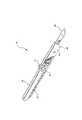
シールド40は、末端側位置と基端側位置との間で移動させるために、細長いハンドル20にスライド自在に装着されている。図2から最もよくわかるように、末端側位置では、シールド40が刃30への不注意な接近を妨げる。この位置では、シールド40の基端は、ハンドル20の末端部に形成されたロック指示線26と概ね一直線になる。ロック指示線26は、刃30がシールド40によって保護された状態で、シールド40が末端側位置でロックされていることを臨床医に視覚的に知らせる。図3から最もよくわかるように、基端側位置では、シールド40が使用のために刃30を露出させる。シールド40が基端側位置にあるときに、シールド40の基端は、肩部22に密に隣接しないと好ましい。代わりに、基端側位置にあるときには、肩部22とシールド40の基端との間に隙間ができる。この隙間は、肩部22とシールド40の基端との間に臨床医の手袋または皮膚が挟まれるのを防ぐ。シールド40は、ポリプロピレン、ポリエチレン、ポリカーボネート、ポリアセタール、ポリアミドなどの熱可塑性材料から形成することができる。特定の用途のために、シールド40の形成に選択される材料をほぼ透明にしてもよい。 The
シールド40は、シールド40の上部表面から上向きに突き出ている、上向きに偏倚された片持ち式の指作動部41を含む。臨床医は、上向きに偏倚された片持ち式の指作動部41に指で十分な圧力をかけて、指作動部41を下方向にたわませ、シールド40を解放して基端側位置と末端側位置との間で移動させることができる。上向きに偏倚された片持ち式の指作動部41は、ハンドル20内に形成されたスロット21と協働して末端側位置と基端側位置との間のシールド40の移動を制御するように設計された少なくとも1つの内向きボス42を含むと好ましい。2つのスロットがハンドル20の片側に形成されている場合、2つの内向きボス42を片持ち式の指作動部41上に形成すると好ましい。 The
スロット21は、ハンドル20の末端部に沿って概ね長手方向に延びている。スロット21は、ハンドル20に対するシールド40の行程長さを画定する。スロット21の場所および長さは、シールド40が基端側位置にあるときにシールド40の基端とハンドル20上の肩部22との間に確実に隙間ができるように選択されると好ましい。このように、隙間によって、確実に臨床医の手袋または皮膚がシールド40の基端と肩部22との間に挟まれなくなる。好ましくは、隙間の長さを0.012インチ(約0.030cm)にするとよい。スロット21は、先が上を向いた末端側終端21aと、先が上を向いた基端側終端21bとの間で延在している。ハンドル20は、先が上を向いた末端側終端および基端側終端をその両側に備えたスロット21を画定すると好ましい。シールド40がそれぞれ末端側位置または基端側位置にあるときには、ボス42は、それぞれ各末端21aおよび21bに係合する。ボス42が末端の1つに係合しているときには、シールド40の移動が妨げられる。臨床医が上向きに偏倚された片持ち式の指作動部41に十分な下向きの力を加えてたわませ、それゆえに、ボス42がもはや末端21aまたは21bに係合しないとき、臨床医は、それによって基端側位置と末端側位置との間でシールド40を望むように選択的に移動させることができる。基端側位置と末端側位置との間を移動する間、ボス42は、シールド40を安定させるようにスロット21内をたどる。末端に到達すると、ボス42は、「パチン(スナップ)」といったボス42が末端に係合したときの可聴音を臨床医に提供する働きをするので、上向きに偏倚された片持ち式の指作動部41を静止位置に戻すことができる。この可聴式の指標は、シールド40の所望の移動が完了したことを臨床医に認識させるのに役立つ。加えて、上向きに偏倚された片持ち式の指作動部41、ボス42および末端21a、21bの構成は、シールド40の所望の移動が完了したことを臨床医に触知させる。 The
基端側縁部が後方に向かってテーパするように、末端側終端21aを形成すると好ましい。上向きに偏倚された片持ち式の指作動部41を押し下げずにシールド40を無理に後方に進めた場合、この構成は、ボス42を上方に向かって押し進ませて末端側終端21aに密に係合させる。したがって、シールド40の末端側位置から基端側位置への不注意な移動が最小限に抑えられる。このテーパは、約60度程度であると好ましい。また、ボス42の上向きの移動を最大限にするために、ボス42の基端側縁部もテーパ化することができる。このテーパは、約55度程度であると好ましい。このテーパの角度は、確実にボス42が末端側終端21a内に完全に嵌合して、ボス42がその中の適切な位置に確実にロックされるように小さくなっている。確実にシールド40を末端側位置の適切な位置で堅固に保持するには、ボス42の長手寸法を、末端側終端21aの長手寸法にほぼ等しく、またはそれよりわずかに小さくすべきである。確実にシールド40を基端側位置の適切な位置で堅固に保持するには、ボス42の長手寸法を基端側終端21bの長手寸法にほぼ等しく、またはそれよりわずかに小さくすべきである。基端側終端21bの長手寸法は、末端側終端21aの長手寸法と同一であると好ましい。 It is preferable to form the
シールド40は、ハンドル20の末端部の外表面にスライド可能に係合するように配置された内向きに突出するラグ46を含むと好ましい。ラグ46がハンドル20の表面に係合すると、シールド40が基端側位置と末端側位置との間で移動する間、シールド40に安定性がもたらされる。それに加えて、ラグ46は、確実にシールド40をハンドル20にぴったりと嵌合させ、特にシールド40が基端側位置にあるときのハンドル20に対するシールド40の望ましくない横方向の移動を妨げる。これは、シールド付外科用メス10の全体的な剛性と、臨床医の手の中における感触とを改善する。 The
また、シールド40は、シールド付外科用メス10の製造プロセス時のシールド40の取扱いを容易にするために、外側に向かって広がるバンプ43を含むと好ましい。バンプ43により、製造プロセス時にシールドを異なるステーション間でコンベヤレールによって運ぶことが可能になる。図9および図10を参照されたい。バンプ43は、シールド40の外部のいずれの場所に配置することも可能であるが、バンプ43をシールド40の一端に向けて配置すべきである。ただし、バンプ43を、シールド40の片側に、その基端に隣接させて配置することが好ましい。バンプ43は、シールド40をコンベヤレールによって運搬可能ないずれかの構成にすることができる。ただし、バンプ43は、シールド40の表面から上方に約0.03インチ(約0.076cm)延びており、短軸約0.12インチ(約0.30cm)、長軸約0.21インチ(約0.53cm)で、丸い外表面を有すると好ましい。 The
シールド40の末端側底縁部44は、使用時に刃30の切断縁部を妨げず、さらにシールド40が末端側位置にあるときにも刃30の切断縁部を覆うように形成されると好ましい。シールドの末端側底縁部44は、標準的な刃の形状に一致するように、半径0.55インチ(約1.4cm)で画定される曲線により形成されると好ましい。シールド40のこの縁部を適正な構成にテーパ化することによって、臨床医は、従来の外科用メスを使用するのと同じように、本発明のシールド付外科用メス10を浅い角度で使用することができる。 The
このように、操作に片手しか必要とせず、そうでなくても操作が容易で故障しにくいシールド付外科用メスが提供されることがわかる。本発明は、数多くの様々な形態の実施形態によって満たされるが、図面に示され、本明細書で詳細に記載される本発明の実施形態において、本開示が本発明の原理を例示するものと見なされるべきであり、本発明の範囲は、例示された実施形態に限定されるものではないことは理解されよう。本発明の範囲は、特許請求の範囲とその均等物とによって判断される。 Thus, it can be seen that there is provided a shielded scalpel that requires only one hand for operation and is easy to operate and less likely to fail. The present invention is fulfilled by a number of different forms of embodiments, but in the embodiments of the invention shown in the drawings and described in detail herein, this disclosure is intended to illustrate the principles of the invention. It should be understood that the scope of the present invention is not limited to the illustrated embodiments. The scope of the invention is determined by the claims and their equivalents.
Claims (11)
Translated fromJapaneseそれらの間に肩部が画定されている基端部および末端部を有し、テーパ化された基端側縁部を有する先が上を向いた末端側終端および先が上を向いた基端側終端を備えて形成されたスロットを画定する細長いハンドルと、
前記ハンドルに固定して取り付けられた刃と、
前記ハンドルに装着されるシールドであって、前記シールドが前記刃への不注意な接近を実質的に妨げる末端側位置と、前記シールドが使用のために前記刃を露出させる基端側位置との間で移動可能なシールドとを備え、前記シールドは、前記スロット内に配置される内向きボスを有する上向きに偏倚された片持ち式の指作動部を含むことを特徴とするシールド付外科用メス。A shielded surgical knife,
A distal end with a proximal end and a distal end with a tapered proximal edge with a proximal end and a distal end with a shoulder defined between them An elongated handle defining a slot formed with side terminations;
A blade fixedly attached to the handle;
A shield attached to the handle, the distal position where the shield substantially prevents inadvertent access to the blade; and a proximal position where the shield exposes the blade for use A shielded scalpel, wherein the shield includes an upwardly biased cantilevered finger actuating portion having an inwardly facing boss disposed in the slot. .
それらの間に肩部が画定されている基端部および末端部を有し、テーパ化された基端側縁部を有する先が上を向いた末端側終端と先が上を向いた基端側終端とを備えて形成されたスロットを画定する細長いハンドルと、 A distal end with a proximal end and a distal end with a tapered proximal edge with a proximal end and a distal end with a shoulder defined between them An elongated handle defining a slot formed with side terminations;
前記ハンドルに固定して取り付けられた刃と、 A blade fixedly attached to the handle;
基端と、前記ハンドルに装着される末端側底縁部とを有するシールドであって、前記シールドが前記刃への不注意な接近を妨げる末端側位置と、前記シールドが使用のために前記刃を露出させる基端側位置との間で移動可能なシールドとを備え、前記シールドは、前記スロット内に配置された内向きボスを有する上向きに偏倚された片持ち式の指作動部を含んでおり、前記細長いハンドルの末端部は、前記シールドの操作の視覚的指示を含み、前記シールドが基端側位置にあるときに前記シールドの基端と前記肩部との間に隙間が画定され、前記シールドの末端側底縁部は、標準的な刃の曲線に一致する曲線を画定することを特徴とするシールド付外科用メス。 A shield having a proximal end and a distal bottom edge attached to the handle, the distal position where the shield prevents inadvertent access to the blade, and the shield being used for the blade A shield that is movable between a proximal position that exposes the shield, the shield including an upwardly biased cantilevered finger actuating portion having an inwardly directed boss disposed in the slot. A distal end of the elongated handle includes a visual indication of operation of the shield, and a gap is defined between the proximal end of the shield and the shoulder when the shield is in a proximal position; A shielded scalpel characterized in that the distal bottom edge of the shield defines a curve that matches a standard blade curve.
Applications Claiming Priority (2)
| Application Number | Priority Date | Filing Date | Title |
|---|---|---|---|
| US09/820,571US6626925B2 (en) | 2001-03-29 | 2001-03-29 | Shielded surgical scalpel |
| PCT/US2002/007323WO2002078550A2 (en) | 2001-03-29 | 2002-03-12 | Shielded surgical scalpel |
Related Child Applications (2)
| Application Number | Title | Priority Date | Filing Date |
|---|---|---|---|
| JP2008267901ADivisionJP4885186B2 (en) | 2001-03-29 | 2008-10-16 | Shielded surgical scalpel |
| JP2008267902ADivisionJP4885187B2 (en) | 2001-03-29 | 2008-10-16 | Shielded surgical scalpel |
Publications (2)
| Publication Number | Publication Date |
|---|---|
| JP2005506108A JP2005506108A (en) | 2005-03-03 |
| JP4230775B2true JP4230775B2 (en) | 2009-02-25 |
Family
ID=25231176
Family Applications (3)
| Application Number | Title | Priority Date | Filing Date |
|---|---|---|---|
| JP2002576821AExpired - LifetimeJP4230775B2 (en) | 2001-03-29 | 2002-03-12 | Shielded surgical scalpel |
| JP2008267902AExpired - LifetimeJP4885187B2 (en) | 2001-03-29 | 2008-10-16 | Shielded surgical scalpel |
| JP2008267901AExpired - LifetimeJP4885186B2 (en) | 2001-03-29 | 2008-10-16 | Shielded surgical scalpel |
Family Applications After (2)
| Application Number | Title | Priority Date | Filing Date |
|---|---|---|---|
| JP2008267902AExpired - LifetimeJP4885187B2 (en) | 2001-03-29 | 2008-10-16 | Shielded surgical scalpel |
| JP2008267901AExpired - LifetimeJP4885186B2 (en) | 2001-03-29 | 2008-10-16 | Shielded surgical scalpel |
Country Status (9)
| Country | Link |
|---|---|
| US (1) | US6626925B2 (en) |
| EP (1) | EP1372497B1 (en) |
| JP (3) | JP4230775B2 (en) |
| AT (1) | ATE369080T1 (en) |
| BR (1) | BRPI0208507B1 (en) |
| CA (1) | CA2441885C (en) |
| DE (1) | DE60221652T2 (en) |
| ES (1) | ES2290324T3 (en) |
| WO (1) | WO2002078550A2 (en) |
Families Citing this family (68)
| Publication number | Priority date | Publication date | Assignee | Title |
|---|---|---|---|---|
| ATE234591T1 (en) | 1999-04-09 | 2003-04-15 | Canica Design Inc | SCALPEL |
| US6645216B2 (en)* | 2002-02-14 | 2003-11-11 | David H. Masury | Surgical scalpel |
| USD482449S1 (en) | 2002-12-27 | 2003-11-18 | Becton Dickinson And Company | Handle |
| USD483123S1 (en) | 2002-12-27 | 2003-12-02 | Becton Dickinson And Company | Blade carrier |
| USD489457S1 (en) | 2002-12-27 | 2004-05-04 | Becton Dickinson And Company | Handle |
| USD482788S1 (en) | 2002-12-27 | 2003-11-25 | Becton Dickinson And Company | Blade carrier |
| USD483124S1 (en) | 2002-12-27 | 2003-12-02 | Becton Dickinson And Company | Handle |
| USD486232S1 (en) | 2002-12-27 | 2004-02-03 | Becton Dickinson And Company | Handle |
| USD490153S1 (en) | 2002-12-27 | 2004-05-18 | Becton Dickinson And Company | Blade carrier |
| USD490154S1 (en) | 2002-12-27 | 2004-05-18 | Becton, Dickinson And Company | Handle |
| USD482122S1 (en) | 2002-12-27 | 2003-11-11 | Becton Dickinson And Company | Handle |
| USD481129S1 (en) | 2003-01-29 | 2003-10-21 | Becton Dickinson And Company | Blade holder |
| US7022128B2 (en)* | 2003-04-22 | 2006-04-04 | Becton, Dickinson And Company | Surgical knife safety handle |
| TW200509851A (en)* | 2003-04-22 | 2005-03-16 | Becton Dickinson Co | Surgical knife safety handle |
| CN2621611Y (en)* | 2003-05-21 | 2004-06-30 | 施国平 | Locking disposable safety lancet |
| US20050033338A1 (en)* | 2003-06-19 | 2005-02-10 | Ferree Bret A. | Surgical instruments particularly suited to severing ligaments and fibrous tissues |
| US7617932B2 (en)* | 2003-09-19 | 2009-11-17 | Diabetes Diagnostics, Inc. | Medical device package, kit and associated methods |
| US20050131433A1 (en)* | 2003-12-10 | 2005-06-16 | Fisher Travis M. | Microkeratome cutting-blade assembly using staking and adhesive |
| USD535399S1 (en) | 2004-03-12 | 2007-01-16 | Griffin Michael D | Safety scalpel holder |
| US7207999B2 (en)* | 2004-03-12 | 2007-04-24 | Griffin Michael D | Safety scalpel |
| US7172611B2 (en)* | 2004-03-22 | 2007-02-06 | Becton, Dickinson And Company | Surgical scalpel assembly |
| US7055248B2 (en)* | 2004-04-30 | 2006-06-06 | Becton, Dickinson And Company | Surgical knife blade attachment and method for using same |
| US20060041266A1 (en)* | 2004-08-17 | 2006-02-23 | Sullivan Stephen J | Surgical scalpel |
| TWI369970B (en) | 2004-10-20 | 2012-08-11 | Beaver Visitec Int Us Inc | Surgical knife safety handle having user operable lock |
| CA2608059C (en) | 2004-10-22 | 2014-06-17 | Canica Design Inc. | Safety scalpel |
| US20060212058A1 (en)* | 2005-03-18 | 2006-09-21 | Ilija Djordjevic | Disposable safety surgical blade |
| US8114103B2 (en)* | 2005-09-14 | 2012-02-14 | James Edwin Rasco | Scalpel blade protector |
| US20090131963A1 (en)* | 2005-09-14 | 2009-05-21 | James Edwin Rasco | Scalpel blade protector |
| US7159713B1 (en) | 2005-11-01 | 2007-01-09 | Georgene Austria | Sharp blade protection device |
| CA2642373C (en)* | 2006-02-27 | 2014-06-03 | Feather Safety Razor Co., Ltd. | Edged tool |
| USD561898S1 (en)* | 2006-02-28 | 2008-02-12 | Feather Safety Razor Co., Ltd. | Blade guard for a surgical knife |
| US20070225763A1 (en)† | 2006-03-23 | 2007-09-27 | Ethicon Endo-Surgery, Inc. | Marked Suture |
| US20070233013A1 (en)* | 2006-03-31 | 2007-10-04 | Schoenberg Stephen J | Covers for tissue engaging members |
| US8959778B2 (en)* | 2007-04-26 | 2015-02-24 | Poly Medicure Limited | Surgical safety scalpel |
| WO2009074863A2 (en)* | 2007-12-11 | 2009-06-18 | Canica Design, Inc. | Safety scalpel |
| US8464430B2 (en) | 2008-02-07 | 2013-06-18 | Beaver-Visitec International (Us), Inc. | Retractable safety knife |
| US8156653B2 (en)* | 2008-07-26 | 2012-04-17 | Georgene Austria | Safety scalpel with blade retention |
| US8256331B2 (en) | 2008-11-20 | 2012-09-04 | Alcon Research, Ltd. | Guarded surgical knife handle |
| US8256330B2 (en)* | 2008-11-20 | 2012-09-04 | Alcon Research, Ltd. | Guarded surgical knife handle |
| US10974406B2 (en)* | 2018-04-27 | 2021-04-13 | Matthew J. Jacobs | Safety utility blades, assemblies and methods of manufacturing |
| US20100305593A1 (en)* | 2009-05-29 | 2010-12-02 | Inzero John R | Safety scalpel |
| WO2011108099A1 (en) | 2010-03-04 | 2011-09-09 | フェザー安全剃刀株式会社 | Cutting tool |
| US8875405B2 (en) | 2010-04-09 | 2014-11-04 | Oasis Medical, Inc. | Micro surgical knife with safety feature |
| CN103501722B (en)* | 2010-12-23 | 2018-01-23 | B·D·罗森汉 | Safety suture cutting instrument and method |
| US8465512B2 (en) | 2011-04-05 | 2013-06-18 | Branden D. Rosenhan | Safety suture cutting device and related methods |
| GB2487950A (en)* | 2011-02-10 | 2012-08-15 | Samuel George | Cutting implement with protective sheath |
| US20120245610A1 (en)* | 2011-03-24 | 2012-09-27 | Southmedic Inc. | Retractable and removable blade unit for a scalpel |
| US8596173B2 (en)* | 2011-07-25 | 2013-12-03 | Conair Corporation | Peeling tool |
| WO2013041982A2 (en)* | 2011-09-23 | 2013-03-28 | Trevor John Milton | Scalpel blade safety accessory |
| US9622773B2 (en) | 2012-03-19 | 2017-04-18 | Aspen Surgical Products, Inc. | Side activated safety scalpel for left and right hand users with blade removal system |
| US9763693B2 (en) | 2012-04-26 | 2017-09-19 | Scalpel Innovation, Inc. | Safety scalpel |
| CN102835992B (en)* | 2012-09-05 | 2014-09-17 | 苏州施莱医疗器械有限公司 | Disposable scalpel blade assembly and assorted non-disposable scalpel handle |
| CN102871706B (en) | 2012-09-05 | 2015-01-07 | 苏州施莱医疗器械有限公司 | Safe scalpel |
| USD755969S1 (en)* | 2012-09-24 | 2016-05-10 | Scalpal Llc | Scalpel tip |
| US9901365B1 (en) | 2013-03-15 | 2018-02-27 | PenBlade, Inc. | Set of safety scalpels |
| WO2015048545A1 (en) | 2013-09-27 | 2015-04-02 | Release Medical, Inc. | Tissue incision device |
| US9901367B2 (en)* | 2014-03-05 | 2018-02-27 | Spectra Medical Devices, Inc. | Safety scalpel |
| US20160095614A1 (en) | 2014-10-03 | 2016-04-07 | Aspen Surgical Products, Inc. | Sharps blade applicator and storage device |
| US10123815B2 (en) | 2015-02-13 | 2018-11-13 | Precision Engineered Products, Llc | Surgical knife |
| USD800905S1 (en) | 2015-03-06 | 2017-10-24 | Aspen Surgical Products, Inc. | Scalpel handle sheath |
| US10575867B2 (en) | 2015-11-20 | 2020-03-03 | A.M. Surgical, Inc. | Shield for endoscopic surgical blade and method of use |
| USD813390S1 (en) | 2016-01-15 | 2018-03-20 | Aspen Surgical Products, Inc. | Surgical scalpel blade attachment |
| US20170265882A1 (en) | 2016-03-21 | 2017-09-21 | Aspen Surgical Products, Inc. | Safety scalpel handle |
| US20180001489A1 (en)* | 2016-07-01 | 2018-01-04 | Slice, Inc. | Craft knife handle |
| CN106236201B (en)* | 2016-09-13 | 2018-09-14 | 苏州施莱医疗器械有限公司 | Sheath type disposable safe scalpel |
| USD831826S1 (en) | 2017-09-05 | 2018-10-23 | Aspen Surgical Products, Inc. | Surgical blade loader |
| US11000309B2 (en)* | 2018-05-31 | 2021-05-11 | Medi-Safe Surgicals (Pty) Ltd | Safety scalpel |
| US20250288316A1 (en)* | 2022-04-29 | 2025-09-18 | Accutec, Inc. | Surgical safety knife |
Family Cites Families (69)
| Publication number | Priority date | Publication date | Assignee | Title |
|---|---|---|---|---|
| US2735176A (en) | 1956-02-21 | Veterinary surgical knife | ||
| US2885780A (en) | 1957-12-03 | 1959-05-12 | Floyd A Campbell | Marking tool |
| US3025598A (en) | 1958-10-13 | 1962-03-20 | Gillette Co | Knife |
| US2968489A (en) | 1959-03-03 | 1961-01-17 | Doniger Sundel | Cutting tools |
| US3657812A (en) | 1970-09-28 | 1972-04-25 | G & L Ind Inc | Retractible tool holder |
| US3793726A (en) | 1972-06-07 | 1974-02-26 | Becton Dickinson Co | Sterile disposable scalpel |
| US3906626A (en)* | 1974-04-19 | 1975-09-23 | Becton Dickinson Co | Disposable surgical scalpel |
| US3905101A (en) | 1974-04-19 | 1975-09-16 | Becton Dickinson Co | Disposable surgical scalpel |
| US4071952A (en)* | 1976-12-17 | 1978-02-07 | Cbs Inc. | Knife and safety cap |
| US4091537A (en) | 1977-04-26 | 1978-05-30 | Stevenson Machine Shop | Safety utility knife |
| US4318473A (en) | 1980-12-15 | 1982-03-09 | Sandel Dan S | Surgical blade removal and disposal device |
| US4375218A (en) | 1981-05-26 | 1983-03-01 | Digeronimo Ernest M | Forceps, scalpel and blood coagulating surgical instrument |
| US4414974A (en) | 1981-06-09 | 1983-11-15 | General Conveyors Limited | Microsurgical knife |
| US4491132A (en) | 1982-08-06 | 1985-01-01 | Zimmer, Inc. | Sheath and retractable surgical tool combination |
| SU1367970A1 (en) | 1983-07-05 | 1988-01-23 | Московский Научно-Исследовательский Институт Микрохирургии Глаза Мз Рсфср | Arrangement for ophthalmological operations |
| US4576164A (en) | 1983-11-14 | 1986-03-18 | Richeson W George | Knife with locking shroud |
| US4523379A (en) | 1984-05-02 | 1985-06-18 | Tekna | Knife with retractable sheath |
| JPS6137842A (en) | 1984-07-30 | 1986-02-22 | Daikin Ind Ltd | Antistatic polymeric material |
| US4660287A (en) | 1985-11-01 | 1987-04-28 | Decker John R | Knife with replaceable blade |
| DE3622342A1 (en) | 1986-07-03 | 1988-01-14 | Beermann Kg Martor Argentax | KNIFE |
| GB2192358B (en) | 1986-07-08 | 1989-12-20 | Shirley Inst The | Knife |
| US4735202A (en) | 1986-10-06 | 1988-04-05 | Alcon Laboratories, Inc. | Microsurgical knife with locking blade guard |
| DE3722899A1 (en) | 1987-07-08 | 1989-01-19 | Peters Tim | Scalpel |
| US4844070A (en) | 1987-10-02 | 1989-07-04 | Dee Robert N | Changeable scalpel blade and chuck assembly |
| SE8800833D0 (en) | 1988-03-09 | 1988-03-09 | Dan Lundgren | SCALPEL |
| US4823457A (en) | 1988-04-20 | 1989-04-25 | American Safety Razor Company | Disposable surgical scalpel |
| USD327125S (en) | 1988-04-20 | 1992-06-16 | American Safety Razor Company | Surgical scalpel handle |
| US4903390A (en) | 1988-10-03 | 1990-02-27 | Vir Engineering, Inc. | Scalpel blade remover and blade storage apparatus |
| US5071426A (en)* | 1989-04-06 | 1991-12-10 | Stuart Dolgin | Surgical scalpel with retractable blade guard |
| US5141517A (en) | 1990-01-16 | 1992-08-25 | Zimmer Inc. | Retractable instrument |
| US5071418A (en) | 1990-05-16 | 1991-12-10 | Joseph Rosenbaum | Electrocautery surgical scalpel |
| US5292310A (en) | 1990-12-27 | 1994-03-08 | Inbae Yoon | Safety needle |
| USD330082S (en) | 1991-01-31 | 1992-10-06 | Schutte Michael J | Scalpel |
| US5197953A (en) | 1991-07-08 | 1993-03-30 | John Colonna | Cap assembly |
| US5309641A (en) | 1991-12-18 | 1994-05-10 | American Safety Razor Company | Disposable surgical scalpel with safety guard |
| US5299357A (en) | 1991-12-18 | 1994-04-05 | American Safety Razor Company | Disposable surgical scalpel with safety guard |
| US5411512A (en) | 1992-01-24 | 1995-05-02 | Leonard Bloom | Guarded surgical scalpel |
| US5496340A (en)* | 1992-01-24 | 1996-03-05 | Leonard Bloom | Combination guarded surgical scalpel and blade stripper |
| US5250063A (en)* | 1992-01-24 | 1993-10-05 | Leonard Bloom | Surgical scalpel with retractable guard |
| US5338310A (en) | 1992-02-06 | 1994-08-16 | Becton, Dickinson And Company | Needle device having safety indication features |
| US5207696A (en) | 1992-04-30 | 1993-05-04 | Medical Sterile Products, Inc. | Surgical scalpel |
| US5201748A (en) | 1992-06-01 | 1993-04-13 | Newman Philip H | Retractable-bladed surgical scalpel |
| US5312429A (en) | 1992-07-27 | 1994-05-17 | Devon Industries, Inc. | Scalpel handle and blade release assembly |
| EP0583992A1 (en) | 1992-08-20 | 1994-02-23 | Winston Daniel Shaer | Shield for scalpel blade |
| US5250064A (en) | 1992-10-07 | 1993-10-05 | Biological Tissue Reserve, Inc. | Shield for surgical scalpel blades |
| US5330492A (en) | 1992-10-21 | 1994-07-19 | Dlh Concepts, Inc. | Safety scalpel |
| US5330494A (en) | 1993-01-22 | 1994-07-19 | Cornelis A. van der Westhuizen | Knife |
| US5344424A (en)* | 1993-03-12 | 1994-09-06 | Roberts Philip L | Selectively retractable, disposable surgical knife |
| US5363958A (en) | 1993-04-14 | 1994-11-15 | Devon Industries, Inc. | Blade arming cartridge |
| US5342379A (en) | 1993-06-01 | 1994-08-30 | Volinsky Fredric G | Safety scalpel |
| US5370654A (en) | 1993-06-18 | 1994-12-06 | Leonard Bloom | Disposable guarded finger scalpel for inserting a line in a patient and method of use thereof |
| US5591189A (en) | 1993-06-24 | 1997-01-07 | Yoon; Inbae | Safety penetrating instrument with safety member moving during penetration and triggered safety member protrusion |
| US5449068A (en) | 1993-10-18 | 1995-09-12 | Devon Industries, Inc. | Surgical blade remover |
| US5465894A (en)* | 1993-12-06 | 1995-11-14 | Ethicon, Inc. | Surgical stapling instrument with articulated stapling head assembly on rotatable and flexible support shaft |
| US5938676A (en) | 1993-12-08 | 1999-08-17 | Becton, Dickinson & Company | Surgical scalpel |
| US5431672A (en) | 1994-05-09 | 1995-07-11 | Becton, Dickinson And Company | Surgical scalpel with retractable blade |
| US5481804A (en) | 1994-10-12 | 1996-01-09 | Platts; David | Retractable-bladed knife |
| US5827309A (en) | 1994-10-25 | 1998-10-27 | Becton, Dickinson And Company | Guarded surgical scalpel with scalpel blade remover |
| US5620454A (en)* | 1994-10-25 | 1997-04-15 | Becton, Dickinson And Company | Guarded surgical scalpel |
| US5571127A (en) | 1995-03-08 | 1996-11-05 | Decampli; William M. | Scalpel handle having retractable blade support and method of use |
| US5683407A (en)* | 1995-10-19 | 1997-11-04 | Becton, Dickinson And Company | Cleanable guarded surgical scalpel with scalpel blade remover |
| US5957944A (en) | 1995-11-07 | 1999-09-28 | Biomet, Inc. | Method for treatment of trigger finger |
| US6357068B1 (en)* | 1996-01-11 | 2002-03-19 | Buck Knives, Inc. | Combination tool with oppositely deploying handles |
| US5673842A (en) | 1996-03-05 | 1997-10-07 | Ethicon Endo-Surgery | Surgical stapler with locking mechanism |
| US5676677A (en) | 1996-03-21 | 1997-10-14 | Landis; Robert M. | Guard for the blade of a knife |
| US5868771A (en) | 1997-07-25 | 1999-02-09 | Pabban Development, Inc. | Scalpel blade cover |
| US5908432A (en) | 1998-03-27 | 1999-06-01 | Pan; Huai C. | Scalpel with retractable blade |
| US5951582A (en)* | 1998-05-22 | 1999-09-14 | Specialized Health Products, Inc. | Lancet apparatus and methods |
| JP4559630B2 (en)* | 1998-11-25 | 2010-10-13 | ユナイテッド ステイツ サージカル コーポレイション | Biopsy system |
- 2001
- 2001-03-29USUS09/820,571patent/US6626925B2/ennot_activeExpired - Lifetime
- 2002
- 2002-03-12WOPCT/US2002/007323patent/WO2002078550A2/enactiveIP Right Grant
- 2002-03-12ESES02757781Tpatent/ES2290324T3/ennot_activeExpired - Lifetime
- 2002-03-12DEDE60221652Tpatent/DE60221652T2/ennot_activeExpired - Lifetime
- 2002-03-12BRBRPI0208507-0Apatent/BRPI0208507B1/ennot_activeIP Right Cessation
- 2002-03-12ATAT02757781Tpatent/ATE369080T1/ennot_activeIP Right Cessation
- 2002-03-12JPJP2002576821Apatent/JP4230775B2/ennot_activeExpired - Lifetime
- 2002-03-12CACA002441885Apatent/CA2441885C/ennot_activeExpired - Fee Related
- 2002-03-12EPEP02757781Apatent/EP1372497B1/ennot_activeExpired - Lifetime
- 2008
- 2008-10-16JPJP2008267902Apatent/JP4885187B2/ennot_activeExpired - Lifetime
- 2008-10-16JPJP2008267901Apatent/JP4885186B2/ennot_activeExpired - Lifetime
Also Published As
| Publication number | Publication date |
|---|---|
| US6626925B2 (en) | 2003-09-30 |
| CA2441885C (en) | 2010-01-05 |
| WO2002078550A3 (en) | 2003-03-13 |
| BR0208507A (en) | 2006-02-21 |
| JP4885186B2 (en) | 2012-02-29 |
| JP2009061288A (en) | 2009-03-26 |
| DE60221652T2 (en) | 2008-05-21 |
| CA2441885A1 (en) | 2002-10-10 |
| ES2290324T3 (en) | 2008-02-16 |
| JP2005506108A (en) | 2005-03-03 |
| DE60221652D1 (en) | 2007-09-20 |
| EP1372497A2 (en) | 2004-01-02 |
| WO2002078550A2 (en) | 2002-10-10 |
| ATE369080T1 (en) | 2007-08-15 |
| US20020143352A1 (en) | 2002-10-03 |
| JP2009095673A (en) | 2009-05-07 |
| EP1372497B1 (en) | 2007-08-08 |
| JP4885187B2 (en) | 2012-02-29 |
| BRPI0208507B1 (en) | 2015-09-01 |
Similar Documents
| Publication | Publication Date | Title |
|---|---|---|
| JP4230775B2 (en) | Shielded surgical scalpel | |
| US5411512A (en) | Guarded surgical scalpel | |
| US5496340A (en) | Combination guarded surgical scalpel and blade stripper | |
| US5620454A (en) | Guarded surgical scalpel | |
| US5545175A (en) | Disposable quarded finger scalpel for inserting a line in a patent and lock off therefor | |
| US5275606A (en) | Guarded scalpel for surgical use | |
| JP3066829B2 (en) | Surgical scalpel | |
| EP0988832B1 (en) | Surgical scalpel | |
| JP5148628B2 (en) | Safety knife with replaceable blade cartridge and safety brake | |
| US20040243161A1 (en) | Disposable guarded surgical scalpel | |
| US20130204284A1 (en) | Surgical Knife Safety Handle | |
| US20050119680A1 (en) | Surgical device with a moveable instrument protector | |
| JP4789951B2 (en) | Surgical safety knife | |
| WO1997037599A1 (en) | Disposable guarded finger scalpel for inserting a line in a patient and blade therefor | |
| AU2007203154B2 (en) | Shielded surgical scalpel | |
| CA2870783C (en) | Safety scalpel | |
| AU2002306689A1 (en) | Shielded surgical scalpel | |
| HK1134767B (en) | Safety scalpel with replaceable blade cartridge and safety brake |
Legal Events
| Date | Code | Title | Description |
|---|---|---|---|
| A621 | Written request for application examination | Free format text:JAPANESE INTERMEDIATE CODE: A621 Effective date:20050311 | |
| A131 | Notification of reasons for refusal | Free format text:JAPANESE INTERMEDIATE CODE: A131 Effective date:20080516 | |
| A601 | Written request for extension of time | Free format text:JAPANESE INTERMEDIATE CODE: A601 Effective date:20080815 | |
| A602 | Written permission of extension of time | Free format text:JAPANESE INTERMEDIATE CODE: A602 Effective date:20080822 | |
| A601 | Written request for extension of time | Free format text:JAPANESE INTERMEDIATE CODE: A601 Effective date:20080916 | |
| A602 | Written permission of extension of time | Free format text:JAPANESE INTERMEDIATE CODE: A602 Effective date:20080924 | |
| A521 | Request for written amendment filed | Free format text:JAPANESE INTERMEDIATE CODE: A523 Effective date:20081016 | |
| TRDD | Decision of grant or rejection written | ||
| A01 | Written decision to grant a patent or to grant a registration (utility model) | Free format text:JAPANESE INTERMEDIATE CODE: A01 Effective date:20081114 | |
| A01 | Written decision to grant a patent or to grant a registration (utility model) | Free format text:JAPANESE INTERMEDIATE CODE: A01 | |
| A61 | First payment of annual fees (during grant procedure) | Free format text:JAPANESE INTERMEDIATE CODE: A61 Effective date:20081204 | |
| R150 | Certificate of patent or registration of utility model | Ref document number:4230775 Country of ref document:JP Free format text:JAPANESE INTERMEDIATE CODE: R150 Free format text:JAPANESE INTERMEDIATE CODE: R150 | |
| FPAY | Renewal fee payment (event date is renewal date of database) | Free format text:PAYMENT UNTIL: 20111212 Year of fee payment:3 | |
| S111 | Request for change of ownership or part of ownership | Free format text:JAPANESE INTERMEDIATE CODE: R313113 | |
| FPAY | Renewal fee payment (event date is renewal date of database) | Free format text:PAYMENT UNTIL: 20111212 Year of fee payment:3 | |
| R350 | Written notification of registration of transfer | Free format text:JAPANESE INTERMEDIATE CODE: R350 | |
| FPAY | Renewal fee payment (event date is renewal date of database) | Free format text:PAYMENT UNTIL: 20111212 Year of fee payment:3 | |
| FPAY | Renewal fee payment (event date is renewal date of database) | Free format text:PAYMENT UNTIL: 20121212 Year of fee payment:4 | |
| R250 | Receipt of annual fees | Free format text:JAPANESE INTERMEDIATE CODE: R250 | |
| FPAY | Renewal fee payment (event date is renewal date of database) | Free format text:PAYMENT UNTIL: 20121212 Year of fee payment:4 | |
| FPAY | Renewal fee payment (event date is renewal date of database) | Free format text:PAYMENT UNTIL: 20131212 Year of fee payment:5 | |
| R250 | Receipt of annual fees | Free format text:JAPANESE INTERMEDIATE CODE: R250 | |
| R250 | Receipt of annual fees | Free format text:JAPANESE INTERMEDIATE CODE: R250 | |
| R250 | Receipt of annual fees | Free format text:JAPANESE INTERMEDIATE CODE: R250 | |
| R250 | Receipt of annual fees | Free format text:JAPANESE INTERMEDIATE CODE: R250 | |
| R250 | Receipt of annual fees | Free format text:JAPANESE INTERMEDIATE CODE: R250 | |
| R250 | Receipt of annual fees | Free format text:JAPANESE INTERMEDIATE CODE: R250 | |
| R250 | Receipt of annual fees | Free format text:JAPANESE INTERMEDIATE CODE: R250 | |
| R250 | Receipt of annual fees | Free format text:JAPANESE INTERMEDIATE CODE: R250 | |
| R250 | Receipt of annual fees | Free format text:JAPANESE INTERMEDIATE CODE: R250 | |
| R250 | Receipt of annual fees | Free format text:JAPANESE INTERMEDIATE CODE: R250 | |
| EXPY | Cancellation because of completion of term |