JP4229141B2 - Vehicle state quantity estimation device and vehicle steering control device using the device - Google Patents
Vehicle state quantity estimation device and vehicle steering control device using the deviceDownload PDFInfo
- Publication number
- JP4229141B2 JP4229141B2JP2006169187AJP2006169187AJP4229141B2JP 4229141 B2JP4229141 B2JP 4229141B2JP 2006169187 AJP2006169187 AJP 2006169187AJP 2006169187 AJP2006169187 AJP 2006169187AJP 4229141 B2JP4229141 B2JP 4229141B2
- Authority
- JP
- Japan
- Prior art keywords
- vehicle
- observation
- state quantity
- reliability
- observed
- Prior art date
- Legal status (The legal status is an assumption and is not a legal conclusion. Google has not performed a legal analysis and makes no representation as to the accuracy of the status listed.)
- Expired - Fee Related
Links
Images


Classifications
- B—PERFORMING OPERATIONS; TRANSPORTING
- B62—LAND VEHICLES FOR TRAVELLING OTHERWISE THAN ON RAILS
- B62D—MOTOR VEHICLES; TRAILERS
- B62D1/00—Steering controls, i.e. means for initiating a change of direction of the vehicle
- B62D1/24—Steering controls, i.e. means for initiating a change of direction of the vehicle not vehicle-mounted
- B62D1/28—Steering controls, i.e. means for initiating a change of direction of the vehicle not vehicle-mounted non-mechanical, e.g. following a line or other known markers
- B—PERFORMING OPERATIONS; TRANSPORTING
- B60—VEHICLES IN GENERAL
- B60W—CONJOINT CONTROL OF VEHICLE SUB-UNITS OF DIFFERENT TYPE OR DIFFERENT FUNCTION; CONTROL SYSTEMS SPECIALLY ADAPTED FOR HYBRID VEHICLES; ROAD VEHICLE DRIVE CONTROL SYSTEMS FOR PURPOSES NOT RELATED TO THE CONTROL OF A PARTICULAR SUB-UNIT
- B60W40/00—Estimation or calculation of non-directly measurable driving parameters for road vehicle drive control systems not related to the control of a particular sub unit, e.g. by using mathematical models
- B60W40/10—Estimation or calculation of non-directly measurable driving parameters for road vehicle drive control systems not related to the control of a particular sub unit, e.g. by using mathematical models related to vehicle motion
Landscapes
- Engineering & Computer Science (AREA)
- Transportation (AREA)
- Mechanical Engineering (AREA)
- Physics & Mathematics (AREA)
- Automation & Control Theory (AREA)
- Mathematical Physics (AREA)
- Chemical & Material Sciences (AREA)
- Combustion & Propulsion (AREA)
- Steering Control In Accordance With Driving Conditions (AREA)
- Control Of Driving Devices And Active Controlling Of Vehicle (AREA)
- Control Of Position, Course, Altitude, Or Attitude Of Moving Bodies (AREA)
- Position Fixing By Use Of Radio Waves (AREA)
Description
Translated fromJapanese本発明は、走行する車両の運動状態を表す状態量を推定する車両状態量推定装置に係り、詳しくは、車両の運動状態をモデル化してその状態量を演算することにより実際の車両の状態量を推定するようにした車両状態量推定装置に関する。また、本発明は、その車両状態量推定装置を用いた車両操舵制御装置に関する。 The present invention relates to a vehicle state quantity estimation device that estimates a state quantity that represents a motion state of a traveling vehicle. More specifically, the present invention relates to an actual vehicle state quantity by modeling a vehicle motion state and calculating the state quantity. The present invention relates to a vehicle state quantity estimation device. The present invention also relates to a vehicle steering control device using the vehicle state quantity estimation device.
従来、車両を自動操舵制御にて予め定めた道路上を運行させる車両運行システムが提案されている。この車両運行システムでは、路面の車両走行軌道に沿って所定間隔にてマーカ(磁気マーカ)が設置され、車両が各マーカを通過するごとに車両に搭載したマーカセンサから出力されるマーカと当該車両との相対的な位置関係を反映した検出信号に基づいて当該車両の車両走行軌道からの横変位を検出している。そして、このマーカ通過ごとに検出される横変位に基づいて車両が車両走行軌道から外れないように操舵制御を行っている。 Conventionally, a vehicle operation system for operating a vehicle on a predetermined road by automatic steering control has been proposed. In this vehicle operation system, markers (magnetic markers) are installed at predetermined intervals along the vehicle traveling trajectory on the road surface, and a marker output from a marker sensor mounted on the vehicle each time the vehicle passes through each marker and the vehicle The lateral displacement of the vehicle from the vehicle running track is detected based on the detection signal reflecting the relative positional relationship between the vehicle and the vehicle. Steering control is performed so that the vehicle does not deviate from the vehicle travel path based on the lateral displacement detected each time the marker passes.
このような車両運行システムにおいて、より精度の高い操舵制御を実現するために、従来、カルマンフィルタを用いて操舵制御に必要な車両のヨー運動及び横運動の状態を表す状態量を推定する手法が提案されている(例えば、特許文献1参照)。この特許文献1に記載の従来技術では、車両がマーカ上を通過するごとに得られる横変位の観測値を用いて車両のヨー運動及び横運動を表す状態量として定義された4つの状態変数(ヨーレート、ヨー角、横変位速度、横変位)の推定値がカルマンフィルタによって演算される。 In order to realize more accurate steering control in such a vehicle operation system, conventionally, a method for estimating a state quantity representing a state of a yaw motion and a lateral motion of a vehicle necessary for the steering control using a Kalman filter has been proposed. (For example, refer to Patent Document 1). In the prior art described in Patent Document 1, four state variables defined as state variables representing yaw motion and lateral motion of a vehicle using observed lateral displacement values obtained each time the vehicle passes over the marker ( Estimated values (yaw rate, yaw angle, lateral displacement speed, lateral displacement) are calculated by a Kalman filter.
そして、その特許文献1に記載の従来技術は、磁気マーカを通過する毎に横変位とヨーレートを観測値として取得しその観測値を用いて車両の状態量の推定値を演算する距離軸カルマンフィルタと、所定周期毎にヨーレートを観測値として取得し前回演算した推定値を用いると共にその観測値を用いて車両の状態量の推定値を演算する時間軸カルマンフィルタとを備え、時間軸カルマンフィルタは、距離軸カルマンフィルタにて推定値が得られるごとに、前回演算した推定値に代えて距離軸カルマンフィルタにて得られた推定値を用いて車両の状態量の推定値を演算するものである。つまり、各磁気マーカで距離軸カルマンフィルタにて得られる推定値を時間軸カルマンフィルタにおける推定に反映させることによって、横変位の観測ができない磁気マーカ間であっても、車両の状態量の推定精度の向上を図ろうとしている。
しかしながら、上述の特許文献1に記載の従来技術では、次の磁気マーカを通過するまで、その直前の磁気マーカを通過するときに距離軸カルマンフィルタにて得られた推定値が、時間軸カルマンフィルタによる推定に反映されているため、磁気マーカ間において車両に横方向に大きな動きがある場合には、磁気マーカ間の状態量の推定誤差が大きくなりやすい傾向がある。すなわち、磁気マーカ間では横変位の観測ができないことにより、実道路形状の施工、ヨーレートドリフト、車両のモデル化などによる誤差が累積しやすいため、距離軸カルマンフィルタにて得られた推定値を時間軸カルマンフィルタに反映する周期が長くなる場合(例えば、曲率の大きなカーブにおいて極低速で走行するような場合)には、磁気マーカ間の時間軸カルマンフィルタによる推定誤差が大きくなりやすい傾向がある。 However, in the conventional technique described in Patent Document 1 described above, the estimated value obtained by the distance axis Kalman filter when passing through the immediately preceding magnetic marker until the next magnetic marker is passed is estimated by the time axis Kalman filter. Therefore, when there is a large lateral movement of the vehicle between the magnetic markers, the estimation error of the state quantity between the magnetic markers tends to increase. That is, since lateral displacement cannot be observed between magnetic markers, errors due to construction of actual road shapes, yaw rate drift, vehicle modeling, etc. are likely to accumulate. When the period reflected in the Kalman filter becomes long (for example, when traveling at a very low speed in a curve with a large curvature), the estimation error due to the time-axis Kalman filter between the magnetic markers tends to increase.
そこで、本発明は、車両の運動状態を表す状態量の推定精度を向上させる車両状態量推定装置の提供を第1の目的とする。また、本発明は、そのような車両状態量推定装置を用いた車両操舵制御装置の提供を第2の目的とする。 Accordingly, a first object of the present invention is to provide a vehicle state quantity estimation device that improves the estimation accuracy of a state quantity representing the motion state of a vehicle. The second object of the present invention is to provide a vehicle steering control device using such a vehicle state quantity estimation device.
上記第1の目的を達成するため、第1の発明は、
車両の運動状態を表す所定状態量を観測する複数の観測手段と、
前記観測手段によって観測された所定状態量を車両の運動状態のモデルに入力して車両の運動状態を表す状態量を推定する推定手段とを有する、車両状態量推定装置であって、
前記観測手段によって観測された所定状態量の信頼度を前記観測手段毎に評価する評価手段を備え、
前記推定手段は、前記複数の観測手段によって観測された複数の所定状態量を前記モデルへ反映させるものであり、
前記観測手段によって観測された所定状態量の前記モデルへの反映度合いが、前記評価手段によって評価された信頼度に基づいて設定され、
前記評価手段は、前記所定状態量が観測された際の観測環境に基づいて前記信頼度を評価し、前記観測環境が観測誤差の大きい環境であるほど前記信頼度を低く評価することを特徴とする。In order to achieve the first object, the first invention provides:
A plurality of observation means for observing a predetermined amount of state representing the motion state of the vehicle;
A vehicle state quantity estimating device comprising: an estimation means for inputting a predetermined state quantity observed by the observation means to a model of a vehicle motion state and estimating a state quantity representing the vehicle motion state;
An evaluation means for evaluating the reliability of the predetermined state quantity observed by the observation means for each observation means;
The estimation means reflects a plurality of predetermined state quantities observed by the plurality of observation means to the model,
The degree of reflection of the predetermined state quantity observed by the observation means on the model is set based on the reliability evaluated by the evaluation means,
The evaluation means evaluates the reliability based on an observation environment when the predetermined state quantity is observed, and evaluates the reliability lower as the observation environment has a larger observation error. To do.
これにより、客観的に把握され得る観測環境が観測誤差の大きい環境であれば前記モデルへの反映度合いを抑えることができるので、観測環境の悪化による観測手段の観測精度の低下に対してロバストな状態量推定が可能となる。 As a result, if the observation environment that can be objectively grasped is an environment with a large observation error, the degree of reflection in the model can be suppressed, so that it is robust against a decrease in observation accuracy of the observation means due to deterioration of the observation environment. The state quantity can be estimated.
また、本発明は、
車両の運動状態を表す所定状態量を観測する複数の観測手段と、
前記観測手段によって観測された所定状態量を車両の運動状態のモデルに入力して車両の運動状態を表す状態量を推定する推定手段とを有する、車両状態量推定装置であって、
前記観測手段によって観測された所定状態量の信頼度を前記観測手段毎に評価する評価手段を備え、
前記推定手段は、前記複数の観測手段によって観測された複数の所定状態量を前記モデルへ反映させるものであり、
前記観測手段によって観測された所定状態量の前記モデルへの反映度合いが、前記評価手段によって評価された信頼度に基づいて設定され、
前記評価手段は、前記所定状態量の観測時点からの経過時間に基づいて前記信頼度を評価し、前記経過時間が長くなるほど前記信頼度を低く評価することを特徴とする。これにより、観測時点からの時間経過により低下するその観測データの正確度を前記モデルに反映させることができるので、観測時点からの時間経過による観測手段の観測精度の低下に対してロバストな状態量推定が可能となる。例えば、実道路の施工誤差や車両モデル誤差の累積が観測時点から生じたとしても、ロバストな状態量推定が可能となる。Thepresent invention also provides:
A plurality of observation means for observing a predetermined amount of state representing the motion state of the vehicle;
A vehicle state quantity estimating device comprising: an estimation means for inputting a predetermined state quantity observed by the observation means to a model of a vehicle motion state and estimating a state quantity representing the vehicle motion state;
An evaluation means for evaluating the reliability of the predetermined state quantity observed by the observation means for each observation means;
The estimation means reflects a plurality of predetermined state quantities observed by the plurality of observation means to the model,
The degree of reflection of the predetermined state quantity observed by the observation means on the model is set based on the reliability evaluated by the evaluation means,
The evaluation means evaluates the reliability based on an elapsed time from the observation time of the predetermined state quantity, and evaluates the reliability lower as the elapsed time becomes longer. As a result, the accuracy of the observation data, which decreases with the passage of time from the observation time, can be reflected in the model, so the state quantity is robust against the deterioration of the observation accuracy of the observation means with the passage of time from the observation time. Estimation is possible. For example, even if actual road construction errors and vehicle model errors accumulate from the time of observation, robust state quantity estimation is possible.
また、本発明は、
車両の運動状態を表す所定状態量を観測する複数の観測手段と、
前記観測手段によって観測された所定状態量を車両の運動状態のモデルに入力して車両の運動状態を表す状態量を推定する推定手段とを有する、車両状態量推定装置であって、
前記観測手段によって観測された所定状態量の信頼度を前記観測手段毎に評価する評価手段を備え、
前記推定手段は、前記複数の観測手段によって観測された複数の所定状態量を前記モデルへ反映させるものであり、
前記観測手段によって観測された所定状態量の前記モデルへの反映度合いが、前記評価手段によって評価された信頼度に基づいて設定され、
前記評価手段は、前記所定状態量の観測時点からの走行距離に基づいて前記信頼度を評価し、前記走行距離が長くなるほど前記信頼度を低く評価することを特徴とする。これにより、観測時点からの走行距離により低下するその観測データの正確度を前記モデルに反映させることができるので、観測時点からの走行距離増加による観測手段の観測精度の低下に対してロバストな状態量推定が可能となる。例えば、実道路の施工誤差や車両モデル誤差の累積が観測時点から生じたとしても、ロバストな状態量推定が可能となる。Thepresent invention also provides:
A plurality of observation means for observing a predetermined amount of state representing the motion state of the vehicle;
A vehicle state quantity estimating device comprising: an estimation means for inputting a predetermined state quantity observed by the observation means to a model of a vehicle motion state and estimating a state quantity representing the vehicle motion state;
An evaluation means for evaluating the reliability of the predetermined state quantity observed by the observation means for each observation means;
The estimation means reflects a plurality of predetermined state quantities observed by the plurality of observation means to the model,
The degree of reflection of the predetermined state quantity observed by the observation means on the model is set based on the reliability evaluated by the evaluation means,
The evaluation means evaluates the reliability based on a travel distance from the observation point of the predetermined state quantity, and evaluates the reliability lower as the travel distance becomes longer. As a result, the accuracy of the observation data, which decreases due to the distance traveled from the observation time, can be reflected in the model, so the state is robust against a decrease in observation accuracy of the observation means due to an increase in travel distance from the observation time. Quantity estimation is possible. For example, even if actual road construction errors and vehicle model errors accumulate from the time of observation, robust state quantity estimation is possible.
また、本発明は、上記のいずれかの発明に係る車両状態量推定装置であって、
前記推定手段は、カルマンフィルタであって、
前記カルマンフィルタの観測方程式に各観測値の観測誤差の標準偏差の項が追加され、
前記信頼度が低く評価されるほど前記標準偏差が大きくなることを特徴とする。Further, thepresent invention is a vehicle state quantity estimation device according to any one of theabove inventions,
The estimation means is a Kalman filter,
A standard deviation term of the observation error of each observation value is added to the observation equation of the Kalman filter,
The standard deviation increases as the reliability is evaluated lower.
また、上記第2の目的を達成するため、本発明として、
上記のいずれかの発明に係る車両状態量推定装置と、
該車両状態量推定装置によって推定された車両の運動状態を表す状態量に基づいて操舵系における操舵アクチュエータに対する制御信号を生成する制御信号生成手段とを備える、車両操舵制御装置を提供する。
In order to achieve the second object, as thepresent invention,
A vehicle state quantity estimating device according to any one of theabove inventions;
There is provided a vehicle steering control device comprising control signal generation means for generating a control signal for a steering actuator in a steering system based on a state quantity representing a motion state of a vehicle estimated by the vehicle state quantity estimation device.
本発明によれば、車両の運動状態を表す状態量の推定精度を向上させる車両状態量推定装置を実現することができる。また、そのような車両状態量推定装置を用いた車両操舵制御装置を実現することができる。 ADVANTAGE OF THE INVENTION According to this invention, the vehicle state quantity estimation apparatus which improves the estimation precision of the state quantity showing the movement state of a vehicle is realizable. In addition, a vehicle steering control device using such a vehicle state quantity estimation device can be realized.
以下、図面を参照して、本発明を実施するための最良の形態の説明を行う。本発明の実施の一形態に係る車両状態量推定装置は、カルマンフィルタを用いて車両の状態量、特に、車両の横方向に係る運動状態(ヨー運動及び横運動)を表す状態量を推定する。具体的には、この車両の横方向に係る運動状態を表す状態量として、例えば、ヨーレート、ヨー角、横変位速度及び横位置(横変位)を推定している。 The best mode for carrying out the present invention will be described below with reference to the drawings. A vehicle state quantity estimation device according to an embodiment of the present invention uses a Kalman filter to estimate a state quantity of a vehicle, in particular, a state quantity representing a motion state (yaw motion and lateral motion) in the lateral direction of the vehicle. Specifically, for example, a yaw rate, a yaw angle, a lateral displacement speed, and a lateral position (lateral displacement) are estimated as state quantities representing the motion state in the lateral direction of the vehicle.
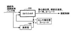
その推定手法について、図1を用いて簡単に説明する。図1において、車両100は、例えば、磁気マーカが離散的に設置された軌道に沿って走行するように操舵制御される。車両100の横方向に係る運動状態は、操舵角、車輪速度、道路曲率、バンク角(カント)などの因子に影響される。その運動状態を表す状態量(ヨーレート、ヨー角、横変位速度、横位置)のうち、ヨーレートがヨーレートセンサからの検出信号に基づいて自律的に観測され、横位置が磁気センサ等のマーカセンサによって磁気マーカが検出されるごとにその検出信号に基づいて観測される。また、同時に、横位置は、車両の位置を特定可能なGPS受信機や軌道に沿って引かれた白線を認識可能な白線認識装置からの検出信号に基づいて自律的にも観測され。 The estimation method will be briefly described with reference to FIG. In FIG. 1, the
カルマンフィルタ200は、上記のような操舵角、車輪速度、道路曲率、バンク角などの因子に影響される車両100の運動状態をモデル化し、これらの因子及び上記のように観測された横位置及びヨーレート、更に前回の推定値を用いてヨーレート、ヨー角、横変位速度及び横位置の推定値を演算する。実際に観測されるヨーレート及び横位置には、ヨーレートセンサやマーカセンサや白線認識測定やGPS測定の雑音成分(測定雑音)が定常的に含まれ、更に、車両100固有の雑音成分(システム雑音)も含まれる。これに対して、カルマンフィルタ200によって状態量(ヨーレート、ヨー角、横変位速度及び横位置)の各推定値を繰り返し演算することによって、当該状態量の各推定値は上記雑音成分が除かれた真の値に収束してゆく。 The
上記のようなカルマンフィルタを用いた車両状態量推定装置を用いた車両の操舵制御装置は、例えば、図2に示すように構成される。図2において、GPS受信機11、白線認識装置12、マーカセンサ13、ヨーレートセンサ14、Gセンサ15、車輪速センサ16及び操舵角センサ17が制御ユニット(ECU)50に接続されている。GPS受信機11は、GPS衛星からの受信情報に基づいて特定された車両の位置に係る座標情報(例えば、緯度及び経度)に応じた検出信号を出力する。白線認識装置12は、軌道に沿って引かれた白線との車両横方向における相対的な位置関係に応じた検出信号を出力する。マーカセンサ13は、磁気マーカ(レーンマーカ)の発する磁気の大きさに応じた検出信号を出力する。したがって、マーカセンサ13は、軌道に沿って離散的に設置された各磁気マーカ上を車両が通過するときにはその磁気マーカとの車両横方向における相対的な位置関係に応じた検出信号を出力する。ヨーレートセンサ14は、走行中の車両のヨーレートに応じた検出信号を出力する。Gセンサ15は、走行中の車両の横加速度に応じた検出信号を出力する。車輪速センサ16は、走行する車両の車輪の回転速度(車両速度に対応)に応じたパルス信号を検出信号として出力する。操舵角センサ17は、操舵輪(前輪)の操舵角度に応じた検出信号を出力する。 A vehicle steering control device using the vehicle state quantity estimation device using the Kalman filter as described above is configured as shown in FIG. 2, for example. In FIG. 2, a
また、メモリユニット20には、車両の走行する道路の形状(曲率、バンク角、道路の車線数、車線幅、標高等)や、周辺道路建造物(家屋、ビル、交差点、踏切、駐車場、有料道路の料金所等)に係る地図情報が座標データとともに予め格納されており、制御ユニット50は、メモリユニット20からこの地図情報を必要に応じて読み出す。メモリユニット20内の地図情報は、車車間通信や路車間通信や所定の管理センターなどの外部との通信を介して、あるいは、CDやDVDなどの媒体を介して、更新可能にしてもよい。 Further, the
制御ユニット50は、上述したようなカルマンフィルタ200の機能及び車両操舵制御の機能を有している。このカルマンフィルタ200の機能により、車両の横方向に係る運動状態を表す状態量(ヨーレート、ヨー角、横変位速度、横位置)の推定演算が行われ、車両操舵制御部31により、推定演算された状態量に基づいて操舵角が演算され、その操舵角に応じた操舵制御信号が出力される。このように制御ユニット50から出力される操舵制御信号に基づいて操舵系に設けられた操舵アクチュエータ32が駆動する。 The
制御ユニット50のカルマンフィルタ200は、
状態変数x=(η,η’,θ,γ)T
影響因子(入力量)u=(δ,κ,α)T
システム雑音w=(wη,wη’,wθ,wγ)T
観測量y=(Dmag,Dgps,Dwl,γy)T
観測誤差標準偏差σ=(σmag,σgps,σwl,σγ)T
と定義したときに、[数1]に示される状態方程式と[数2]に示される観測方程式を定式化する。なお、「()T」は、転置行列を示す。また、η’と数式中の「ドットη」は、同義である。The
State variable x = (η, η ′, θ, γ)T
Influence factor (input amount) u = (δ, κ, α)T
System noise w = (wη, wη ′, wθ, wγ)T
Observed quantity y = (Dmag, Dgps, Dwl, γy)T
Observation error standard deviation σ = (σmag, σgps, σwl, σγ)T
, The state equation shown in [Equation 1] and the observation equation shown in [Equation 2] are formulated. “()T ” indicates a transposed matrix. Further, η ′ and “dot η” in the equation are synonymous.

η:車両重心の横位置
η’:車両重心の横変位速度(車両重心の横位置微分)
θ:道路接線方向に対するヨー角
γ:ヨーレート
δ:操舵角(操舵角センサ17により検出)
κ:道路曲率(地図情報から取得)
α:バンク角(地図情報から取得)
Dmag,Dgps,Dwl:横位置(観測値)
γy:ヨーレート(観測値)
wη,wη’,wθ,wγ:状態量のシステム雑音
V:車速(車輪速センサ11により検出)
g:重力加速度
m:車両質量
I:ヨー慣性質量
Kf,Kr:前・後輪のコーナリングパワー
lf,lr:重心と前・後輪との間の距離
L:重心から車両前端までの距離
と定義される。なお、観測方程式[数2]における観測誤差標準偏差σについての説明は後述する。
η: lateral position of vehicle center of gravity η ′: lateral displacement speed of vehicle center of gravity (lateral position derivative of vehicle center of gravity)
θ: Yaw angle relative to road tangential direction γ: Yaw rate δ: Steering angle (detected by steering angle sensor 17)
κ: Road curvature (obtained from map information)
α: Bank angle (obtained from map information)
Dmag, Dgps, Dwl: Horizontal position (observed value)
γy: Yaw rate (observed value)
wη, wη ′, wθ, wγ: System noise of state quantity V: Vehicle speed (detected by wheel speed sensor 11)
g: Gravity acceleration m: Vehicle mass I: Yaw inertia mass Kf, Kr: Cornering power of front and rear wheels lf, lr: Distance between the center of gravity and front / rear wheels L: Definition of the distance from the center of gravity to the front end of the vehicle Is done. The observation error standard deviation σ in the observation equation [Equation 2] will be described later.
上記各変数は、図3に示すような座標系において定義される。即ち、曲率κの軌道R(目標軌跡)の接線ξと垂直な方向ηに車両100(二輪モデル)の重心Gが位置するように車両100と軌道Rとの関係が設定される。そして、重心Gを原点とした車両前後左右方向の座標系x−yにて重心Gと前・後車輪との距離lf,lrが定義される。また、状態量としてのヨーレートγは、重心G回りのヨーレートとして定義される。横位置Dは、上記方向ηにおける軌道Rからマーカセンサ(車両先端に設置)までの距離として定義される。状態量としてのヨー角θは、軌道Rの接線方向ξと車両の前後方向xとのなす角度として定義される。 Each of the above variables is defined in a coordinate system as shown in FIG. That is, the relationship between the
上記の状態方程式[数1]と観測方程式[数2]に基づき、カルマンフィルタ200によって状態量(ヨーレート、ヨー角、横変位速度及び横位置)の各推定値を繰り返し演算することによって、当該状態量の各推定値は上記雑音成分が除かれた真の値に収束してゆく。なお、カルマンフィルタ200での処理にて推定値を繰り返し演算する過程で、状態方程式[数1]に示す微分方程式を解く際に前回得られた推定値が用いられる。 Based on the state equation [Equation 1] and the observation equation [Equation 2], each estimated value of the state quantity (yaw rate, yaw angle, lateral displacement speed, and lateral position) is repeatedly calculated by the
さらに、カルマンフィルタ200では、前回予測した推定誤差共分散行列PK(t/t−1)を用いて、今回の推定誤差共分散行列PK(t/t)を求めるために、[数3]に示される共分散方程式を定式化する。そして、カルマンフィルタ200では、共分散方程式[数3]を解き、今回の推定誤差共分散行列PK(t/t)を決定する。さらに、カルマンフィルタ200では、今回決定した推定誤差共分散行列PK(t/t)を用いて、次回の推定誤差共分散行列PK(t+1/t)を予測するために、[数4]に示される共分散方程式を解き、次回の推定誤差共分散行列PK(t+1/t)を予測する。Further, the
それでは、カルマンフィルタ200で実際に行う処理について説明する。カルマンフィルタ200では、状態方程式[数1]と観測方程式[数2]を解くために、[数10]で表されるフィルタ方程式を立てる。ただし、数式中の「ハットx」は、xの推定値であることを示す。カルマンフィルタ200では、今回の観測量y(t)と前回予測した状態量x(t/t−1)を用いて、フィルタ方程式[数3]を解き、今回の状態量x(t)を決定する。さらに、カルマンフィルタ200では、今回決定した状態量x(t/t)と今回の入力量u(t)を用いて、次回の状態量x(t+1/t)を予測するために、[数11]に示すフィルタ方程式を立てる。そして、カルマンフィルタ200では、フィルタ方程式[数11]の方程式を解き、次回の状態量x(t+1/t)を予測する。この次回の状態量x(t+1/t)は、次回の状態量xを決定する際に用いられる。Now, processing actually performed by the
さらに、カルマンフィルタ200では、前回予測した推定誤差共分散行列PK(t/t−1)を用いて、[数3]の共分散方程式を解き、今回の推定誤差共分散行列PK(t/t)を決定する。さらに、カルマンフィルタ200では、今回決定した推定誤差共分散行列PK(t/t)を用いて、[数4]の共分散方程式を解き、次回の推定誤差共分散行列PK(t+1/t)を予測する。このように、カルマンフィルタ200では、車両の状態量としての今回の状態量xと推定誤差共分散行列PKを求める。具体的には、車両の状態量としての横位置η、横変位速度η’、ヨー角θ、ヨーレートγの推定値が得られる。Further, the
制御ユニット50は、例えば、図4に示す手順での処理を実行している。図4に示す手順での処理は、隣接する磁気マーカ間において複数回演算できるような所定の演算周期で、上記の状態方程式[数1]と観測方程式[数2]に基づき、カルマンフィルタ200の推定演算により、車両の状態量の推定値を演算している。 For example, the
図4において、車両の走行中に図2に示されるような各センサの検出信号が取得される(ステップ10)。取得された検出信号に基づいて各センサによる車両の横位置Dが冗長的に演算される。すなわち、GPS受信機11からの検出信号に基づいて車両の横位置Dgpsが演算され、白線認識装置12からの検出信号に基づいて車両の横位置Dwlが演算され、マーカセンサ13からの検出信号に基づいて車両の横位置Dmagが演算される。また、ヨーレートセンサ14からの検出信号に基づいて検出ヨーレートγyが取得される。このように取得された各横位置D及び検出ヨーレートγyを用いてカルマンフィルタ200により車両の状態量の推定値が演算されることになる。 In FIG. 4, the detection signals of the sensors as shown in FIG. 2 are acquired while the vehicle is traveling (step 10). The lateral position D of the vehicle by each sensor is redundantly calculated based on the acquired detection signal. That is, the lateral position Dgps of the vehicle is calculated based on the detection signal from the
このステップ10において、観測方程式[数2]における観測誤差標準偏差σを算出する前提として、横位置Dや検出ヨーレートγyなどに係る各センサの検出信号が取得されるとともに、その検出値に対する各センサの単体信頼度が取得される。 In this step 10, as a premise for calculating the observation error standard deviation σ in the observation equation [Equation 2], the detection signals of the respective sensors relating to the lateral position D, the detected yaw rate γy, etc. are acquired, and the respective sensors for the detected values Is obtained.
センサの単体信頼度とは、自身が出力する検出信号についてセンサ自身が主観的に判断した正確さの度合いを示すものである。すなわち、各センサは、自身の検出結果がその検出状況ではどのくらい正確なものであるのかを主観的に判断することが可能である。そこで、各センサは、自身の検出結果に関して主観的に判断した正確度を単体信頼度として制御ユニット50に送信する。例えば、各センサは、自身が把握する検出状況が検出誤差の大きくなりやすい状況であれば、単体信頼度は低いと判断する。また、単体信頼度は、例えば0〜100の間の値に数値化する。各センサの単体信頼度について、以下説明する。 The single unit reliability of the sensor indicates the degree of accuracy that the sensor itself has subjectively determined for the detection signal output by itself. That is, each sensor can subjectively determine how accurate its detection result is in its detection status. Therefore, each sensor transmits the accuracy subjectively determined with respect to its own detection result to the
GPS受信機11の単体信頼度は、例えば、GPSで使用される位置精度劣化度PDOP(Position Dilution of Precision)に応じて設定される。PDOPは、観測点位置の誤差と衛星位置の誤差の関係を表現する指数であって、数値が小さいほど位置精度がよいことを示す。GPS受信機11は、PDOPが小さいほど単体信頼度を高く算出し、その算出された単体信頼度を検出信号とともに制御ユニット50に出力する。例えば、GPS受信機11は、演算式『単体信頼度=100−PDOP×10(PDOPが10以上の場合は10とする)』に従って、単体信頼度を設定する。 The single unit reliability of the
白線認識装置12の単体信頼度は、輝度差、白線の平行度、トラッキング度などの自身の白線認識結果に応じて設定される。白線認識装置12は、輝度差が大きいほど単体信頼度を高く算出し、白線の平行度が高いほど単体信頼度を高く算出し、白線のトラッキング度が大きいほど単体信頼度を高く算出し、その算出された単体信頼度を検出信号とともに制御ユニット50に出力する。 The single line reliability of the white
マーカセンサ(磁気センサ)13の単体信頼度は、磁力密度分布形状、磁力強度などに応じて設定される。マーカセンサ13は、検出された磁力密度分布形状が理想分布に近いほど単体信頼度を高く算出し、磁力強度が大きいほど単体信頼度を高く算出し、その算出された単体信頼度を検出信号とともに制御ユニット50に出力する。 The single unit reliability of the marker sensor (magnetic sensor) 13 is set according to the magnetic density distribution shape, the magnetic strength, and the like. The
ヨーレートセンサ14の単体信頼度は、例えば、検出信号の周波数成分のスペクトル強度に応じて設定される。ヨーレートセンサ14は、車両の動きとは考えにくい高周波成分(例えば、10Hz)以上の周波数成分が多くなるほど単体信頼度を低く算出し、その算出された単体信頼度を検出信号とともに制御ユニット50に出力する。 The single unit reliability of the
Gセンサ15の単体信頼度は、例えば、検出信号の周波数成分のスペクトル強度に応じて設定される。Gセンサ15は、車両の動きとは考えにくい高周波成分(10Hz)以上の周波数成分が多くなるほど単体信頼度を低く算出し、その算出された単体信頼度を検出信号とともに制御ユニット50に出力する。 The single unit reliability of the
車輪速センサ16の単体信頼度は、例えば、検出信号の出力パルスの形状に応じて設定される。パンク等によるタイヤの弾性変化やその他の異常が発生すると出力パルスのスペクトル分布が変化するので、車輪速センサ16は、パターンマッチングなどを用いて出力パルスの形状がその車輪速における理想パルス形状に近いほど単体信頼度を高く算出し、その算出された単体信頼度を検出信号とともに制御ユニット50に出力する。 The single unit reliability of the
また、上述のように図4のステップ10において各センサの単体信頼度が取得される一方で、各センサの走行環境信頼度が算出される(ステップ20)。 Further, as described above, the single unit reliability of each sensor is acquired in step 10 of FIG. 4, while the driving environment reliability of each sensor is calculated (step 20).
センサの走行環境信頼度とは、センサから取得した検出信号について制御ユニット50が客観的に判断した正確さの度合いを示すものである。すなわち、制御ユニット50は、センサの検出結果がその検出状況ではどのくらい正確なものであるのかを客観的に判断することが可能である。センサの検出結果がその検出状況によっては必ずしも正確な値であるとは限らないという考えに基づくものである。そこで、制御ユニット50は、センサの検出結果に関して客観的に判断した正確度を走行環境信頼度として算出する。例えば、制御ユニット50は、センサが検出動作をした際の検出環境が検出誤差の大きくなりやすい状況であれば、走行環境信頼度は低いと算出する。また、走行環境信頼度は、例えば0〜100の間の値に数値化する。各センサの走行環境信頼度について、以下説明する。 The driving environment reliability of the sensor indicates the degree of accuracy that the
GPS受信機11の走行環境信頼度は、例えば、車両周囲の建造物の状態(例えば、その形状や配置)に応じて設定される。制御ユニット50は、メモリユニット20内の地図情報に基づいて、トンネルやビル街などGPS衛星からの電波が届きにくい場所に車両が存在する場合には走行環境信頼度を低く算出する。 The driving environment reliability of the
白線認識装置12の走行環境信頼度は、天候、日照、路面材質などに応じて設定される。制御ユニット50は、白線が認識しにくい検出状況の場合には走行環境信頼度を低めに設定する。雨や曇りの場合には晴れの場合に比べ走行環境信頼度を低く算出し、夜間の場合には昼間に比べ走行環境信頼度を低く算出し、路面材質がコンクリートの場合にはアスファルトの場合に比べ走行環境信頼度を低く算出する。 The driving environment reliability of the white
マーカセンサ13の走行環境信頼度は、磁石埋設誤差、地磁気、道路構造材料などに応じて設定される。制御ユニット50は、施工により磁石埋設誤差が大きい場所では小さい場所に比べ走行環境信頼度を低く算出し、地磁気が強い場所では弱い場所に比べ走行環境信頼度を低く算出し、道路構造材料に磁性体が使用されている橋梁などの場所では使用されていない場所に比べ走行環境信頼度を低く算出する。 The traveling environment reliability of the
ヨーレートセンサ14やGセンサ15や車輪速センサ16の走行環境信頼度は、路面粗さ、路面のうねり、路面材質などに応じて設定される。制御ユニット50は、路面粗さや路面のうねりが大きい場所では小さい場所に比べ走行環境信頼度を低く算出する。 The traveling environment reliability of the
また、各センサの走行環境信頼度を設定するための共通の要素として、車両形状(車高、車幅、全長)、車種、ボディ材質などが挙げられる。制御ユニット50は、例えば、センサの搭載車両がバスやトラックの場合には普通乗用車の場合に比べ、センサに車両の振動が伝わりやすいため、走行環境信頼度を低く算出する。 Common elements for setting the driving environment reliability of each sensor include vehicle shape (vehicle height, vehicle width, total length), vehicle type, body material, and the like. For example, when the vehicle on which the sensor is mounted is a bus or a truck, the
上述のように図4のステップ10において各センサの単体信頼度が取得されるとともに、ステップ20において各センサの走行環境信頼度が算出されると、各センサの総合信頼度が算出される(ステップ30)。 As described above, when the unit reliability of each sensor is acquired in step 10 of FIG. 4 and the travel environment reliability of each sensor is calculated in
センサの総合信頼度とは、上述の単体信頼度と走行環境信頼度を加味した、各センサの検出信号の正確さの度合いを示すものである。総合信頼度Raは、 The total reliability of the sensor indicates the degree of accuracy of the detection signal of each sensor in consideration of the above-described single unit reliability and traveling environment reliability. The overall reliability Ra is
劣化係数Kは、例えば、 The deterioration coefficient K is, for example,
ここで、[数13]の新鮮度について図5を参照しながら説明する。新鮮度はセンサ毎に決められる。各センサはそれぞれ所定の計測周期でデータを観測するところ、計測時点の観測データの信頼性は高いが、計測時点から時間が経過するにつれてその計測時点のおける観測データの信頼性は低下する(つまり、観測データの新鮮度が減少する)と考えることができる。 Here, the freshness of [Equation 13] will be described with reference to FIG. Freshness is determined for each sensor. When each sensor observes data at a predetermined measurement cycle, the reliability of the observation data at the measurement time is high, but the reliability of the observation data at the measurement time decreases as time passes from the measurement time (that is, , The freshness of the observation data decreases).
例えば、カーブを走行している場合や車両の走行が安定していない場合などにおける計測時点からの観測データの変化度合いは、直線道路を走行している場合や車両が安定走行している場合に比べて、大きいと考えられるため(特に、横位置は大きく変化している可能性が高い)、計測時点から時間が経過するにつれてその時点における観測データの新鮮度は減少しているとみなすことができる。 For example, the degree of change in the observed data from the time of measurement when driving on a curve or when the vehicle is not stable is when the vehicle is traveling on a straight road or when the vehicle is traveling stably. In comparison, it is considered that it is large (especially, it is highly possible that the horizontal position has changed significantly), so that the freshness of the observation data at that time may be considered to decrease as time passes from the time of measurement. it can.
そこで、[数13][数14]に示されるように、車両の横方向に係る運動状態に影響を与える因子である道路曲率κとヨーレートγの項を加えることによって、道路曲率κが大きいほどヨーレートγが大きいほど新鮮度が下がるように新鮮度を算出する演算式が設定され、[数12]に示されるように新鮮度が下がれば総合信頼度Raも下がるように総合信頼度Raを算出する演算式が設定されている。また、センサによっては、計測時点でその計測が失敗する場合もある。そこで、図5に示されるように、計測失敗時はそのまま新鮮度を減少させて、総合信頼度Raの算出に反映する。 Therefore, as shown in [Equation 13] and [Equation 14], as the road curvature κ increases, the terms of road curvature κ and yaw rate γ, which are factors affecting the motion state in the lateral direction of the vehicle, are added. An arithmetic expression for calculating the freshness is set so that the freshness decreases as the yaw rate γ increases. As shown in [Equation 12], the overall reliability Ra is calculated so that the overall reliability Ra decreases as the freshness decreases. An arithmetic expression to be set is set. Depending on the sensor, the measurement may fail at the time of measurement. Therefore, as shown in FIG. 5, when the measurement fails, the freshness is reduced as it is and reflected in the calculation of the total reliability Ra.
なお、[数14]は計測間隔が時間ではなく距離で規定する場合(すなわち、所定間隔毎に設置されている磁気マーカを通過するタイミング毎に計測する場合)、経過時間tを経過距離sに、周期Tを磁気マーカ設置距離間隔Sに置き換えることができる。これは、マーカセンサ13の場合に適用すればよく、 [Equation 14] indicates that the elapsed time t is set to the elapsed distance s when the measurement interval is defined by distance instead of time (that is, when measurement is performed at each timing when the magnetic marker is installed at every predetermined interval). The period T can be replaced with the magnetic marker installation distance interval S. This may be applied to the case of the
上述のように図4のステップ30において各センサの総合信頼度が算出されると、総合信頼度は上述の観測方程式[数2]における観測誤差標準偏差σに反映される(ステップ40)。観測誤差標準偏差σは、センサが計測した観測データが信頼できるかどうかを表す指標である。観測データの誤差が大きくなるほど観測誤差標準偏差σは大きくなる。この観測誤差標準偏差σに上述のように算出された総合信頼度Raを反映させる。総合信頼度Raを観測誤差標準偏差σに反映させる考え方として、総合信頼度Raが小さくなるほど観測誤差標準偏差σが大きな値になるように設定する。したがって、総合信頼度Raの観測誤差標準偏差σへの反映手法の一例として、センサ毎に最良の計測状態における標準偏差をシミュレーションなどによって予め算出しておき、その最良計測状態での標準偏差をσminとすると、観測誤差標準偏差σは、 When the total reliability of each sensor is calculated in
したがって、上述のように算出された観測誤差標準偏差σを観測方程式[数2]に代入して、上述したカルマンフィルタ200の推定演算により、状態量(横位置η、横変位速度η’,ヨー角θ,ヨーレートγ)の推定値が演算される(図4のステップ50)。 Accordingly, the observation error standard deviation σ calculated as described above is substituted into the observation equation [Equation 2], and the state quantity (lateral position η, lateral displacement speed η ′, yaw angle) is calculated by the estimation calculation of the
このように観測方程式[数2]に観測誤差標準偏差σの項が存在することによって、カルマンフィルタ200は、観測誤差標準偏差σが大きくなると、その観測データは信頼がおけないとして、演算処理することになる。観測方程式[数2]にもあるように、GPS受信機11に基づいて横位置Dgpsが観測され、白線認識装置12に基づいて横位置Dwlが観測され、マーカセンサ13に基づいて横位置Dmagが観測されており、横位置Dについては冗長的に観測されている。したがって、冗長的に観測された横位置Dのうち、観測誤差標準偏差の小さいセンサの観測データのほうが演算に使われやすくなり、観測誤差標準偏差の大きいセンサの観測データのほうが演算に使われにくくなる。 Thus, when the term of the observation error standard deviation σ exists in the observation equation [Equation 2], the
上記のようにしてカルマンフィルタ200での処理により状態量の推定値が演算されると、その推定値を用いて制御すべき操舵角δが次式に従って演算される(図4のステップ60)。操舵角δは、 When the estimated value of the state quantity is calculated by the process in the
したがって、本実施形態によれば、各センサの処理結果に基づく単体信頼度と制御ユニット50が計測状況に応じた各センサの長短所を考慮した走行環境信頼度から総合信頼度を算出し、また、非同期の各センサが計測したタイミングからの経過時間(あるいは経過距離)に従って減少する新鮮度を算出し、それらの算出された総合信頼度と新鮮度を観測誤差標準偏差σに反映させてカルマンフィルタの推定を行っているので、磁気マーカ間であっても直前に計測した横変位をカルマンフィルタの状態推定に使用し、カルマンフィルタによる状態量推定の精度や信頼性を向上させることができる。すなわち、磁気マーカ間での状態量の推定値の正確性を維持することができ、磁気マーカなどを設置した所定のチェックポイントにて状態量を観測する周期が長くなっても、より正確な車両の状態量の推定ができるような車両状態量推定装置を実現することができる。また、より高い精度での車両の操舵制御が可能な、そのような車両状態量推定装置を用いた車両操舵制御装置を実現することができる。 Therefore, according to the present embodiment, the total reliability is calculated from the unit reliability based on the processing result of each sensor and the driving environment reliability considering the advantages and disadvantages of each sensor according to the measurement situation, The degree of freshness that decreases according to the elapsed time (or elapsed distance) from the timing measured by each asynchronous sensor is calculated, and the calculated total reliability and freshness are reflected in the observation error standard deviation σ. Since the estimation is performed, the lateral displacement measured immediately before the magnetic marker can be used for the Kalman filter state estimation, and the accuracy and reliability of the state quantity estimation by the Kalman filter can be improved. That is, the accuracy of the estimated value of the state quantity between the magnetic markers can be maintained, and even if the period for observing the state quantity at a predetermined checkpoint where the magnetic marker is installed becomes longer, a more accurate vehicle It is possible to realize a vehicle state quantity estimating device that can estimate the state quantity of the vehicle. In addition, it is possible to realize a vehicle steering control device using such a vehicle state quantity estimation device that can perform steering control of the vehicle with higher accuracy.
以上、本発明の好ましい実施例について詳説したが、本発明は、上述した実施例に制限されることはなく、本発明の範囲を逸脱することなく、上述した実施例に種々の変形及び置換を加えることができる。 The preferred embodiments of the present invention have been described in detail above. However, the present invention is not limited to the above-described embodiments, and various modifications and substitutions can be made to the above-described embodiments without departing from the scope of the present invention. Can be added.
例えば、本発明は、図6に示されるカルマンフィルタの構成にも実施することが可能である。図6に示されるカルマンフィルタは、磁気マーカが検出されるごとにカルマンフィルタ200aの機能に従って車両100の状態量(ヨーレート、ヨー角、横変位速度、横位置)の推定値を演算する距離軸カルマンフィルタと,所定周期ごとにカルマンフィルタ200bの機能に従って車両100の状態量(ヨーレート、ヨー角、横変位速度、横位置)の推定値を演算する時間軸カルマンフィルタを備える。図6に示されるカルマンフィルタは、磁気マーカ通過時に横位置とヨーレートを観測値として状態推定する距離軸カルマンフィルタ200aの推定値で、ヨーレートのみを観測値として状態推定する時間軸カルマンフィルタ200bの状態量を初期化することで、横位置の計測が不能な磁気マーカ間の状態量の推定精度を向上させるものである。距離軸カルマンフィルタ200aと時間軸カルマンフィルタ200bのそれぞれに対して、上述の総合信頼度と信頼度を観測誤差標準偏差σに反映させた上記の状態方程式[数1]と観測方程式[数2]と同様の定式化を行えば、状態量推定の精度や信頼性が向上する。 For example, the present invention can also be implemented in the configuration of the Kalman filter shown in FIG. The Kalman filter shown in FIG. 6 is a distance axis Kalman filter that calculates an estimated value of a state quantity (yaw rate, yaw angle, lateral displacement speed, lateral position) of the
また、上述の実施例では、走行環境信頼度の算出を車両毎に行っていたが、走行環境信頼度のデータベースを構築して、各車両がそのデータベースから走行環境信頼度を取得してもよい。例えば、各センサの計測結果及びその単体信頼度、並びに、各センサの計測時の走行状態、天候及び路面状況などの同一地点における計測情報を各車両が所定の管理センターに送信する。一方、その管理センターは、各車両からそれらの計測情報を取得し、走行状況、天候、路面状況などを指標に各センサの信頼度データベースを統計的に構築する。そして、各車両は、管理センターから路車間通信などの通信回線を介して、信頼度データベース内の走行環境信頼度を取得し、上述の状態量推定に利用すればよい。これにより、各車両において算出される走行環境信頼度に比べ、より客観性の高い走行環境信頼度を導き出すことができるようになる。 In the above-described embodiment, the travel environment reliability is calculated for each vehicle. However, a travel environment reliability database may be constructed, and each vehicle may acquire the travel environment reliability from the database. . For example, each vehicle transmits measurement information at the same point, such as the measurement result of each sensor and its single unit reliability, and the traveling state, weather, and road surface condition at the time of measurement by each sensor, to a predetermined management center. On the other hand, the management center acquires the measurement information from each vehicle, and statistically constructs a reliability database of each sensor using the running status, weather, road surface status, and the like as indexes. And each vehicle should just acquire the traveling environment reliability in a reliability database via communication lines, such as road-to-vehicle communication, from a management center, and may utilize it for the above-mentioned state quantity estimation. As a result, it is possible to derive a driving environment reliability with higher objectivity than the driving environment reliability calculated for each vehicle.
また、上述の実施例では、カルマンフィルタを例に挙げたが、センサによって観測された所定状態量を車両の運動状態のモデルに入力して車両の運動状態を表す状態量を推定する推定器は、特にカルマンフィルタに限定されない。この推定器は、繰り返し演算することによって推定値が求まるべき真の値に収束するものであればよい。推定器は、その推定処理の中で、センサの計測値をどれぐらい信用して推定するかを決める数値(本実施例のカルマンフィルタでいえば、観測誤差標準偏差σ)にそのセンサの信頼度を反映させればよい。 In the above-described embodiment, the Kalman filter is taken as an example. However, the estimator that inputs the predetermined state quantity observed by the sensor to the model of the vehicle movement state and estimates the state quantity representing the vehicle movement state is as follows. In particular, it is not limited to the Kalman filter. This estimator only needs to converge to a true value to be obtained by repeatedly calculating. In the estimation process, the estimator adds the reliability of the sensor to a numerical value (the observation error standard deviation σ in the case of the Kalman filter in this embodiment) that determines how much the measured value of the sensor is to be estimated. Reflect it.
11 GPS受信機
12 白線認識装置
13 マーカセンサ
14 ヨーレートセンサ
15 Gセンサ
16 車輪速センサ
17 操舵角センサ
20 メモリユニット
31 操舵制御部
32 操舵アクチュエータ
50 制御ユニット
100 車両
200 カルマンフィルタDESCRIPTION OF
Claims (7)
Translated fromJapanese前記観測手段によって観測された所定状態量を車両の運動状態のモデルに入力して車両の運動状態を表す状態量を推定する推定手段とを有する、車両状態量推定装置であって、
前記観測手段によって観測された所定状態量の信頼度を前記観測手段毎に評価する評価手段を備え、
前記推定手段は、前記複数の観測手段によって観測された複数の所定状態量を前記モデルへ反映させるものであり、
前記観測手段によって観測された所定状態量の前記モデルへの反映度合いが、前記評価手段によって評価された信頼度に基づいて設定され、
前記評価手段は、前記所定状態量が観測された際の観測環境に基づいて前記信頼度を評価し、前記観測環境が観測誤差の大きい環境であるほど前記信頼度を低く評価する、車両状態量推定装置。A plurality of observation means for observing a predetermined amount of state representing the motion state of the vehicle;
A vehicle state quantity estimating device comprising: an estimation means for inputting a predetermined state quantity observed by the observation means to a model of a vehicle motion state and estimating a state quantity representing the vehicle motion state;
An evaluation means for evaluating the reliability of the predetermined state quantity observed by the observation means for each observation means;
The estimation means reflects a plurality of predetermined state quantities observed by the plurality of observation means to the model,
The degree of reflection of the predetermined state quantity observed by the observation means on the model is set based on the reliability evaluated by the evaluation means,
The evaluation means evaluates the reliability based on an observation environment when the predetermined state quantity is observed, and evaluates the reliability lower as the observation environment is an environment having a larger observation error. Estimating device.
前記経過時間が長くなるほど前記信頼度を低く評価する、請求項1に記載の車両状態量推定装置。 The vehicle state quantity estimation device according to claim 1, wherein the reliability is evaluated to be lower as the elapsed time becomes longer.
前記走行距離が長くなるほど前記信頼度を低く評価する、請求項1に記載の車両状態量推定装置。The evaluation means evaluates the reliability based on a travel distance from the observation time of the predetermined state quantity,
The vehicle state quantity estimation device according to claim 1, wherein the reliability is evaluated to be lower as the travel distance becomes longer .
前記観測手段によって観測された所定状態量を車両の運動状態のモデルに入力して車両の運動状態を表す状態量を推定する推定手段とを有する、車両状態量推定装置であって、
前記観測手段によって観測された所定状態量の信頼度を前記観測手段毎に評価する評価手段を備え、
前記推定手段は、前記複数の観測手段によって観測された複数の所定状態量を前記モデルへ反映させるものであり、
前記観測手段によって観測された所定状態量の前記モデルへの反映度合いが、前記評価手段によって評価された信頼度に基づいて設定され、
前記評価手段は、前記所定状態量の観測時点からの経過時間に基づいて前記信頼度を評価し、前記経過時間が長くなるほど前記信頼度を低く評価する、車両状態量推定装置。A plurality of observation means for observing a predetermined amount of state representing the motion state of the vehicle;
A vehicle state quantity estimating device comprising: an estimation means for inputting a predetermined state quantity observed by the observation means to a model of a vehicle motion state and estimating a state quantity representing the vehicle motion state;
An evaluation means for evaluating the reliability of the predetermined state quantity observed by the observation means for each observation means;
The estimation means reflects a plurality of predetermined state quantities observed by the plurality of observation means to the model,
The degree of reflection of the predetermined state quantity observed by the observation means on the model is set based on the reliability evaluated by the evaluation means,
The evaluation unit evaluates the reliability based on an elapsed time from the observation time of the predetermined state quantity, and evaluates the reliability lower as the elapsed time becomes longer.
前記観測手段によって観測された所定状態量を車両の運動状態のモデルに入力して車両の運動状態を表す状態量を推定する推定手段とを有する、車両状態量推定装置であって、
前記観測手段によって観測された所定状態量の信頼度を前記観測手段毎に評価する評価手段を備え、
前記推定手段は、前記複数の観測手段によって観測された複数の所定状態量を前記モデルへ反映させるものであり、
前記観測手段によって観測された所定状態量の前記モデルへの反映度合いが、前記評価手段によって評価された信頼度に基づいて設定され、
前記評価手段は、前記所定状態量の観測時点からの走行距離に基づいて前記信頼度を評価し、前記走行距離が長くなるほど前記信頼度を低く評価する、車両状態量推定装置。A plurality of observation means for observing a predetermined amount of state representing the motion state of the vehicle;
A vehicle state quantity estimating device comprising: an estimation means for inputting a predetermined state quantity observed by the observation means to a model of a vehicle motion state and estimating a state quantity representing the vehicle motion state;
An evaluation means for evaluating the reliability of the predetermined state quantity observed by the observation means for each observation means;
The estimation means reflects a plurality of predetermined state quantities observed by the plurality of observation means to the model,
The degree of reflection of the predetermined state quantity observed by the observation means on the model is set based on the reliability evaluated by the evaluation means,
The said evaluation means evaluates the said reliability based on the travel distance from the observation time of the said predetermined state quantity, The vehicle state-quantity estimation apparatus which evaluates the said reliability low as the said travel distance becomes long .
前記カルマンフィルタの観測方程式に各観測値の観測誤差の標準偏差の項が追加され、
前記信頼度が低く評価されるほど前記標準偏差が大きくなる、請求項1から5のいずれかに記載の車両状態量推定装置。The estimation means is a Kalman filter,
A standard deviation term of the observation error of each observation value is added to the observation equation of the Kalman filter,
The vehicle statequantity estimation device according to claim 1, wherein the standard deviation increases as the reliability is evaluated to be lower.
該車両状態量推定装置によって推定された車両の運動状態を表す状態量に基づいて操舵系における操舵アクチュエータに対する制御信号を生成する制御信号生成手段とを備える、車両操舵制御装置。The vehicle state quantity estimating device according to any one of claims 1 to 6,
A vehicle steering control device, comprising: a control signal generation unit configured to generate a control signal for a steering actuator in a steering system based on a state quantity representing a motion state of a vehicle estimated by the vehicle state quantity estimation device.
Priority Applications (6)
| Application Number | Priority Date | Filing Date | Title |
|---|---|---|---|
| JP2006169187AJP4229141B2 (en) | 2006-06-19 | 2006-06-19 | Vehicle state quantity estimation device and vehicle steering control device using the device |
| EP07789423AEP2029414B1 (en) | 2006-06-19 | 2007-06-18 | Vehicle state quantity predicting apparatus and vehicle steering controller using the same, and a method for predicting a vehicle state quantity and vehicle steering controlling method using the same |
| PCT/IB2007/001623WO2007148193A2 (en) | 2006-06-19 | 2007-06-18 | Vehicle state quantity predicting apparatus and vehicle steering controller using the same, and a method for predicting a vehicle state quantity and vehicle steering controlling method using the same |
| CN200780022642XACN101472782B (en) | 2006-06-19 | 2007-06-18 | Vehicle state quantity predicting apparatus and method, and vehicle steering controller and control method |
| US12/226,746US8090493B2 (en) | 2006-06-19 | 2007-06-18 | Vehicle state quantity predicting apparatus and vehicle steering controller using the same, and a method for predicting a vehicle state quantity and vehicle steering controlling method using the same |
| DE602007002907TDE602007002907D1 (en) | 2006-06-19 | 2007-06-18 | VEHICLE SIZE PRECISION DEVICE AND THIS USE VEHICLE STEERING CONTROL, AND USE THEREOF VEHICLE STEERING PROCEDURE |
Applications Claiming Priority (1)
| Application Number | Priority Date | Filing Date | Title |
|---|---|---|---|
| JP2006169187AJP4229141B2 (en) | 2006-06-19 | 2006-06-19 | Vehicle state quantity estimation device and vehicle steering control device using the device |
Publications (2)
| Publication Number | Publication Date |
|---|---|
| JP2007331715A JP2007331715A (en) | 2007-12-27 |
| JP4229141B2true JP4229141B2 (en) | 2009-02-25 |
Family
ID=38670491
Family Applications (1)
| Application Number | Title | Priority Date | Filing Date |
|---|---|---|---|
| JP2006169187AExpired - Fee RelatedJP4229141B2 (en) | 2006-06-19 | 2006-06-19 | Vehicle state quantity estimation device and vehicle steering control device using the device |
Country Status (6)
| Country | Link |
|---|---|
| US (1) | US8090493B2 (en) |
| EP (1) | EP2029414B1 (en) |
| JP (1) | JP4229141B2 (en) |
| CN (1) | CN101472782B (en) |
| DE (1) | DE602007002907D1 (en) |
| WO (1) | WO2007148193A2 (en) |
Cited By (1)
| Publication number | Priority date | Publication date | Assignee | Title |
|---|---|---|---|---|
| JP2020064015A (en)* | 2018-10-18 | 2020-04-23 | 株式会社ショーワ | State quantity estimation device, control device, and state quantity estimation method |
Families Citing this family (34)
| Publication number | Priority date | Publication date | Assignee | Title |
|---|---|---|---|---|
| US9302630B2 (en)* | 2007-11-13 | 2016-04-05 | Tk Holdings Inc. | System and method for receiving audible input in a vehicle |
| ATE535429T1 (en)* | 2007-12-31 | 2011-12-15 | Renault Trucks | METHOD AND DEVICE FOR PREVENTING EXCESSIVE SPEED THROUGH VEHICLE SPEED PREDICTION |
| DE102008012816A1 (en)* | 2008-03-06 | 2009-09-10 | Bayerische Motoren Werke Aktiengesellschaft | Method for detecting driving situations of motor vehicle, involves generating situation characteristics as function of information data of vehicle environment and information data on motion state of vehicle |
| DE102008033821B4 (en)* | 2008-07-19 | 2018-01-04 | Audi Ag | Method and device arrangement for improving information for at least one vehicle system |
| FR2949852B1 (en)* | 2009-09-07 | 2011-12-16 | Sagem Defense Securite | METHOD AND SYSTEM FOR DETERMINING PROTECTION LIMITS WITH INTEGRATED EXTRAPOLATION ON A TEMPORAL TIME HORIZON |
| CN101691124B (en)* | 2009-10-16 | 2012-06-27 | 重庆大学 | Method for controlling electronic power steering system of vehicle without sensor |
| DE102010063984A1 (en)* | 2010-02-11 | 2011-08-11 | Continental Teves AG & Co. OHG, 60488 | Vehicle sensor node |
| DE102011106163A1 (en)* | 2011-06-30 | 2013-01-03 | Lucas Automotive Gmbh | Device for protecting control system of motor vehicle, has microcontroller which generates control signal corresponding to the wheel output of wheel speed values such that the control system of motor vehicle is switched to safe state |
| JP5692044B2 (en)* | 2011-12-21 | 2015-04-01 | トヨタ自動車株式会社 | Vehicle state quantity estimation device, vehicle steering control device |
| US9116233B2 (en)* | 2012-07-10 | 2015-08-25 | Broadcom Corporation | Power mode control for sensors |
| DE102013213067B4 (en)* | 2013-07-04 | 2018-09-20 | Volkswagen Aktiengesellschaft | Method and device for determining at least one state variable of an own position of a vehicle |
| WO2016020762A2 (en)* | 2014-08-04 | 2016-02-11 | TaKaDu Ltd. | A system and method for assessing sensors' reliability |
| JP6263453B2 (en)* | 2014-08-25 | 2018-01-17 | 株式会社豊田中央研究所 | Momentum estimation device and program |
| US10235817B2 (en) | 2015-09-01 | 2019-03-19 | Ford Global Technologies, Llc | Motion compensation for on-board vehicle sensors |
| US9821847B2 (en)* | 2015-11-24 | 2017-11-21 | Deere & Company | Method for guiding an off-road vehicle along a curved path |
| US10494789B2 (en) | 2016-01-06 | 2019-12-03 | Cnh Industrial America Llc | System and method for autonomous steering control of work vehicles |
| JP6677533B2 (en)* | 2016-03-01 | 2020-04-08 | クラリオン株式会社 | In-vehicle device and estimation method |
| JP6689659B2 (en)* | 2016-04-19 | 2020-04-28 | クラリオン株式会社 | Position estimation device and estimation method |
| JP6747182B2 (en)* | 2016-08-30 | 2020-08-26 | 愛知製鋼株式会社 | Attitude detection system for vehicles |
| US10703359B2 (en)* | 2017-01-27 | 2020-07-07 | Ford Global Technologies, Llc | Controlling vehicle orientation |
| US11008039B2 (en)* | 2017-04-12 | 2021-05-18 | Toyota Jidosha Kabushiki Kaisha | Lane change assist apparatus for vehicle |
| DE102017111926A1 (en) | 2017-05-31 | 2018-12-06 | Infineon Technologies Ag | Process control circuit and method for controlling a processing arrangement |
| DE102017222776A1 (en)* | 2017-12-14 | 2019-06-19 | Volkswagen Aktiengesellschaft | Method and system for determining a rack force, operating assistance method for a working device, operation assistance device and working device |
| US10408638B2 (en)* | 2018-01-04 | 2019-09-10 | Mitsubishi Electric Research Laboratories, Inc. | System and method for controlling a vehicle under sensor uncertainty |
| US20190227176A1 (en)* | 2018-01-23 | 2019-07-25 | GM Global Technology Operations LLC | Gnss localization using vehicle sensors |
| DE112018007121B4 (en) | 2018-03-23 | 2021-10-14 | Mitsubishi Electric Corporation | Path generator and vehicle control system |
| CN111208807A (en)* | 2018-11-06 | 2020-05-29 | 苏州艾吉威机器人有限公司 | AGV motion control method based on B spline curve |
| JP7012001B2 (en)* | 2018-11-27 | 2022-01-27 | ヤンマーパワーテクノロジー株式会社 | Vehicle posture estimation device |
| JP7171425B2 (en)* | 2018-12-27 | 2022-11-15 | フォルシアクラリオン・エレクトロニクス株式会社 | Movement estimation device |
| JP7179644B2 (en)* | 2019-02-25 | 2022-11-29 | 三菱重工エンジニアリング株式会社 | Control device, moving body and control method |
| EP3953236B1 (en)* | 2019-04-12 | 2023-06-07 | Volvo Truck Corporation | A method of determining an allowable vehicle state space for an articulated vehicle |
| JP2023112476A (en)* | 2022-02-01 | 2023-08-14 | 日置電機株式会社 | Measuring device, measuring unit, sensor and program |
| DE102023205863A1 (en)* | 2023-06-22 | 2024-12-24 | Magna powertrain gmbh & co kg | Method for determining non-directly measurable driving state variables of a vehicle |
| CN116968752B (en)* | 2023-09-04 | 2024-03-12 | 安徽蔚来智驾科技有限公司 | Method, device, system and storage medium for determining yaw rate |
Family Cites Families (18)
| Publication number | Priority date | Publication date | Assignee | Title |
|---|---|---|---|---|
| JPH06288776A (en)* | 1992-04-20 | 1994-10-18 | Sumitomo Electric Ind Ltd | Azimuth detector |
| JP3269927B2 (en)* | 1994-11-30 | 2002-04-02 | 本田技研工業株式会社 | Vehicle steering control device |
| JPH08263790A (en)* | 1995-03-23 | 1996-10-11 | Honda Motor Co Ltd | Vehicle steering control device |
| JP3441562B2 (en)* | 1995-06-23 | 2003-09-02 | 本田技研工業株式会社 | Yaw rate estimator and yaw rate sensor failure diagnosis device |
| JP3120724B2 (en) | 1996-03-13 | 2000-12-25 | トヨタ自動車株式会社 | Automatic traveling equipment for vehicles |
| JP3694104B2 (en)* | 1996-05-01 | 2005-09-14 | 本田技研工業株式会社 | Yaw rate sensor fault diagnosis device |
| JP3201282B2 (en)* | 1996-09-30 | 2001-08-20 | 三菱自動車工業株式会社 | Vehicle yaw rate estimation device |
| JP3754150B2 (en)* | 1996-10-21 | 2006-03-08 | 本田技研工業株式会社 | Vehicle travel control device |
| JP4028033B2 (en)* | 1997-08-21 | 2007-12-26 | 本田技研工業株式会社 | Steering control device |
| JP2001034341A (en) | 1999-07-19 | 2001-02-09 | Toyota Motor Corp | Vehicle state quantity estimation device and vehicle steering control device using the device |
| JP2001242242A (en)* | 2000-02-29 | 2001-09-07 | Hitachi Ltd | Millimeter wave radar device with detection performance improvement function |
| DE10191529D2 (en)* | 2000-04-19 | 2004-07-08 | Continental Teves Ag & Co Ohg | Method for online determination of driving dynamics for a motor vehicle |
| JP3700614B2 (en)* | 2001-06-22 | 2005-09-28 | 株式会社豊田自動織機 | Parking assistance device |
| NL1018627C2 (en)* | 2001-07-25 | 2003-01-28 | Skf Ab | Control unit for control via wire. |
| EP1663694A1 (en)* | 2003-09-23 | 2006-06-07 | DaimlerChrysler AG | Method and device for recognising lane changing operations for a motor vehicle |
| JP2005132291A (en)* | 2003-10-31 | 2005-05-26 | Denso Corp | Vehicle control system |
| JP4990629B2 (en) | 2003-12-24 | 2012-08-01 | オートモーティブ システムズ ラボラトリー インコーポレーテッド | Road curvature estimation system |
| JP4899626B2 (en) | 2006-05-15 | 2012-03-21 | トヨタ自動車株式会社 | Travel control device |
- 2006
- 2006-06-19JPJP2006169187Apatent/JP4229141B2/ennot_activeExpired - Fee Related
- 2007
- 2007-06-18USUS12/226,746patent/US8090493B2/ennot_activeExpired - Fee Related
- 2007-06-18DEDE602007002907Tpatent/DE602007002907D1/enactiveActive
- 2007-06-18WOPCT/IB2007/001623patent/WO2007148193A2/enactiveApplication Filing
- 2007-06-18CNCN200780022642XApatent/CN101472782B/ennot_activeExpired - Fee Related
- 2007-06-18EPEP07789423Apatent/EP2029414B1/ennot_activeCeased
Cited By (2)
| Publication number | Priority date | Publication date | Assignee | Title |
|---|---|---|---|---|
| JP2020064015A (en)* | 2018-10-18 | 2020-04-23 | 株式会社ショーワ | State quantity estimation device, control device, and state quantity estimation method |
| US12370856B2 (en) | 2018-10-18 | 2025-07-29 | Hitachi Astemo, Ltd. | State quantity estimation device, control device, and state quantity estimation method |
Also Published As
| Publication number | Publication date |
|---|---|
| EP2029414A2 (en) | 2009-03-04 |
| WO2007148193A3 (en) | 2008-02-21 |
| WO2007148193A2 (en) | 2007-12-27 |
| JP2007331715A (en) | 2007-12-27 |
| DE602007002907D1 (en) | 2009-12-03 |
| US8090493B2 (en) | 2012-01-03 |
| US20090093924A1 (en) | 2009-04-09 |
| CN101472782A (en) | 2009-07-01 |
| EP2029414B1 (en) | 2009-10-21 |
| CN101472782B (en) | 2011-08-31 |
Similar Documents
| Publication | Publication Date | Title |
|---|---|---|
| JP4229141B2 (en) | Vehicle state quantity estimation device and vehicle steering control device using the device | |
| JP2008077349A (en) | Vehicle state quantity estimation device and vehicle steering control device using the device | |
| CN101793528B (en) | System and method of lane path estimation using sensor fusion | |
| JP4586795B2 (en) | Vehicle control device | |
| US7034742B2 (en) | Road curvature estimation and automotive target state estimation system | |
| JP5269024B2 (en) | Road surface state estimation device and road surface state estimation method | |
| Stahl et al. | ROS-based localization of a race vehicle at high-speed using LIDAR | |
| US20050225477A1 (en) | Road curvature estimation system | |
| CN102209658A (en) | Method and system for determining road data | |
| CN111373269B (en) | Method and system for determining an effective wind speed for a motor vehicle | |
| CN106840179A (en) | A kind of intelligent vehicle localization method based on multi-sensor information fusion | |
| JP2005539288A5 (en) | ||
| CN107764265B (en) | Method for vehicle positioning feedback | |
| CN105509738A (en) | Inertial navigation/Doppler radar combination-based vehicle positioning and orientation method | |
| JP4899626B2 (en) | Travel control device | |
| CN107274721A (en) | Many vehicle cooperative localization methods in a kind of intelligent transportation system | |
| CN112378410A (en) | Vehicle driving blind area calibration method, device, equipment and storage medium | |
| Heirich et al. | Probabilistic localization method for trains | |
| CN117376920A (en) | Intelligent network connection automobile network attack detection, safety state estimation and control method | |
| Do et al. | Onboard model-based prediction of tram braking distance | |
| Barrios et al. | Multiple model framework of adaptive extended Kalman filtering for predicting vehicle location | |
| Dean et al. | Terrain-based road vehicle localization on multi-lane highways | |
| CN115046547B (en) | A self-driving car positioning system and method in a complex urban environment | |
| Chipka et al. | Autonomous urban localization and navigation with limited information | |
| CN115046546A (en) | Automatic driving automobile positioning system and method based on lane line identification |
Legal Events
| Date | Code | Title | Description |
|---|---|---|---|
| A977 | Report on retrieval | Free format text:JAPANESE INTERMEDIATE CODE: A971007 Effective date:20080414 | |
| A131 | Notification of reasons for refusal | Free format text:JAPANESE INTERMEDIATE CODE: A131 Effective date:20080422 | |
| A521 | Written amendment | Free format text:JAPANESE INTERMEDIATE CODE: A523 Effective date:20080619 | |
| TRDD | Decision of grant or rejection written | ||
| A01 | Written decision to grant a patent or to grant a registration (utility model) | Free format text:JAPANESE INTERMEDIATE CODE: A01 Effective date:20081111 | |
| A01 | Written decision to grant a patent or to grant a registration (utility model) | Free format text:JAPANESE INTERMEDIATE CODE: A01 | |
| A61 | First payment of annual fees (during grant procedure) | Free format text:JAPANESE INTERMEDIATE CODE: A61 Effective date:20081124 | |
| R151 | Written notification of patent or utility model registration | Ref document number:4229141 Country of ref document:JP Free format text:JAPANESE INTERMEDIATE CODE: R151 | |
| FPAY | Renewal fee payment (event date is renewal date of database) | Free format text:PAYMENT UNTIL: 20111212 Year of fee payment:3 | |
| FPAY | Renewal fee payment (event date is renewal date of database) | Free format text:PAYMENT UNTIL: 20111212 Year of fee payment:3 | |
| FPAY | Renewal fee payment (event date is renewal date of database) | Free format text:PAYMENT UNTIL: 20121212 Year of fee payment:4 | |
| FPAY | Renewal fee payment (event date is renewal date of database) | Free format text:PAYMENT UNTIL: 20131212 Year of fee payment:5 | |
| LAPS | Cancellation because of no payment of annual fees |