JP4227676B2 - Gas purification equipment - Google Patents
Gas purification equipmentDownload PDFInfo
- Publication number
- JP4227676B2 JP4227676B2JP24972097AJP24972097AJP4227676B2JP 4227676 B2JP4227676 B2JP 4227676B2JP 24972097 AJP24972097 AJP 24972097AJP 24972097 AJP24972097 AJP 24972097AJP 4227676 B2JP4227676 B2JP 4227676B2
- Authority
- JP
- Japan
- Prior art keywords
- gas
- tower
- product gas
- converter
- cos
- Prior art date
- Legal status (The legal status is an assumption and is not a legal conclusion. Google has not performed a legal analysis and makes no representation as to the accuracy of the status listed.)
- Expired - Lifetime
Links
Images


Classifications
- Y—GENERAL TAGGING OF NEW TECHNOLOGICAL DEVELOPMENTS; GENERAL TAGGING OF CROSS-SECTIONAL TECHNOLOGIES SPANNING OVER SEVERAL SECTIONS OF THE IPC; TECHNICAL SUBJECTS COVERED BY FORMER USPC CROSS-REFERENCE ART COLLECTIONS [XRACs] AND DIGESTS
- Y02—TECHNOLOGIES OR APPLICATIONS FOR MITIGATION OR ADAPTATION AGAINST CLIMATE CHANGE
- Y02P—CLIMATE CHANGE MITIGATION TECHNOLOGIES IN THE PRODUCTION OR PROCESSING OF GOODS
- Y02P20/00—Technologies relating to chemical industry
- Y02P20/50—Improvements relating to the production of bulk chemicals
- Y02P20/52—Improvements relating to the production of bulk chemicals using catalysts, e.g. selective catalysts
Landscapes
- Industrial Gases (AREA)
- Gas Separation By Absorption (AREA)
- Catalysts (AREA)
Description
Translated fromJapanese【0001】
【発明の属する技術分野】
本発明は、石炭ガス化プロセス等の生成ガスの湿式の精製装置に係わり、特に、ガス中の硫黄化合物やその他の不純物の除去処理が容易に可能であるとともに、この除去処理のための生成ガスの冷却及び再加熱を行う熱交換器の容量が格段に低減できるガス精製装置に関する。
【0002】
【従来の技術】
近年、石油資源の枯渇、価格の高騰から、燃料の多様化が叫ばれ、石炭や重質油の利用技術開発が進められており、その一つとして、石炭や重質油をガス化して発電燃料や合成原料とする技術が注目されている。また、ガス化ガスによる発電は、石炭や石油による従来の火力発電に比較して効率が良いので、有限な資源の有効利用の点からも注目されている。
【0003】
しかし、このガス化生成ガスには、数100〜数1000ppmの硫黄化合物(主に硫化水素)が含まれ、これは公害防止のため、或いは後流機器(例えばガスタービン等)の腐食防止等のため、除去する必要が有る。この除去方法としては、例えば特開平7−48584号公報に示されるように、ガスを吸収液に気液接触させる湿式のガス精製技術が知られている。
【0004】
なお、ガス化生成ガスに含まれる硫黄化合物としては、H2S(硫化水素)の他に、100ppm程度のCOS(硫化カルボニル)が含有されているが、これは吸収液では除去できない。
このため、このCOSを湿式のガス精製で除去するには、吸収液とガスとの気液接触を行う脱硫塔の前流で、予めCOSを加水分解反応によりH2Sに変換しておく必要がある。そして従来、この変換のための触媒としては、例えば特公昭63−11053号公報や特開平1−223197号公報に示されるように、酸化チタンをベースにし、LiやNaなどの添加剤を加えたものが知られている。
【0005】
【発明が解決しようとする課題】
ところで、上記従来のガス精製技術では、生成ガスに含まれる塩素化合物(HCl)や窒素化合物(NH3)等の有害な不純物については特に考慮されておらず、改善が望まれていた。
すなわち、一般に石炭ガス化プロセス等の生成ガスには、例えば100〜1500ppm程度のNH3と、例えば100ppm程度のHClが含有されるので、さらなるクリーン化のためにはこれらを除去する必要がある。
【0006】
なお、このうち塩素化合物であるHClは、強酸であってステンレス材に対しても腐食性があり、設備材料を保護する観点から特になるべく前流側で除去する必要があるとともに、生成ガスがガスタービン等で燃焼してなる排煙中に含有されるかたちで大気中に排出される塩素化合物の量を低減するためにも除去する必要がある。
【0007】
また、窒素化合物であるアンモニアは、一般にアミン化合物よりなる吸収液(アルカリ性)を用いた脱硫塔における気液接触処理ではほとんど除去されず、ガスタービン等で燃焼して有害な窒素酸化物となり、ガスタービン等の後流側に一般的に設けられる脱硝装置の負荷を増大させるので問題であった。
【0008】
そこで出願人は、脱硫塔の前流で生成ガス(以降、生成ガスを単にガスと記載する場合がある。)を洗浄液に気液接触させてガスを洗浄し前記不純物を除去する技術を提案しているが、この場合、この洗浄を行う洗浄塔と前述のCOSの変換を行うCOS変換器との位置関係や、生成ガスの熱を有効利用するための熱交換器などの機器構成が問題となる。
【0009】
すなわち、発明者らの知見によれば、HClに代表されるガス中のハロゲン化物などの不純物は、COSをH2Sに変換する一般的な触媒の活性を害することが分っており、このような活性低下を回避するため、前記洗浄塔をCOS変換器の前流に設けて、予め前記不純物を洗浄除去する構成が好ましいものと考えられていた。
【0010】
しかし、COS変換器の性能(変換率)はガスの温度が低い程低下する傾向にあり、この場合性能を実用的なレベルとするためには、洗浄塔での洗浄液との接触により冷却されたガスを再加熱して、最低でも150℃程度とする必要がある。また、脱硫塔での性能を確保するためには、COS変換器を出て脱硫塔に入るガスの温度を40℃程度まで低下させるのが好ましい。
【0011】
さらに、ガスタービン等に送られる処理後のガスをより高温状態に維持して高い熱効率を実現するためには、洗浄塔に導入される前の高温のガスから熱回収して脱硫塔を出た処理後のガスを加熱する必要もある。
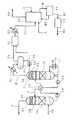
このため、洗浄塔をCOS変換器より前流に配置する構成の場合には、機器構成が、例えば図7に示すような複雑な構成となり、設備の大型化及び高コスト化を招くので、実用上大きな問題となっていた。
【0012】
なお図7の装置構成において、符号Q1で示すものは、ガス化炉(図示省略)を出てスチームヒータ(図示省略)で熱回収された後、ポーラスフィルタ等(図示省略)で除塵されてなる精製処理前の生成ガスであり、その温度は420℃程度である。
そしてこの生成ガスQ1は、まず熱交換器101に導入され、この生成ガスQ1の熱で処理後のガスQ4が加熱され、生成ガスQ1の温度は逆に177℃程度に低下する。
【0013】
次いで生成ガスQ1は、洗浄塔102に導入され、洗浄液との接触により塩化水素やアンモニアなどの不純物が吸収除去されるとともに冷却されて、ガスの温度が露点温度(40℃程度)まで低下したガスQ2となる。
次いで洗浄塔102を出たガスQ2は、熱交換器103に導入され、後述のガスQ3の熱で加熱されて120℃程度とされ、その後加熱器104に導入されてさらに加熱され、150℃程度となる。
【0014】
次いで加熱器104を出たガスQ2は、蒸気QWを加えられて前流で凝縮した水分が補われた後、前述の触媒が装填されたCOS変換器105に導入され、含有しているCOSがH2Sに変換されて、COSをほとんど含有しないガスQ3となる。
次いでCOS変換器105を出たガスQ3は、前述の熱交換器103で逆に冷却され、150℃程度から72℃程度とされた後、さらに冷却器106で工業用水等との熱交換によりさらに冷却されて、結局40℃程度とされて脱硫塔107に導入される。
【0015】
次いで脱硫塔107では、アミン系の吸収剤を含む吸収液との気液接触により、ガスQ3中のH2Sが除去されて、最終的に硫黄分やその他の不純物をほとんど含まないクリーンなガスQ4(温度は42℃程度)として排出される。
次に脱硫部107を出たガスQ4は、前述の熱交換器101により加熱されて、温度が300℃程度まで高められ、クリーンかつ高温な精製処理後のガス化ガスQ5として複合発電システムのガスタービンなどに送られる。
【0016】
そして、このような図7に示す構成であると、二つの熱交換器101,103の伝熱面積が、それぞれ2262m2,2898m2となり、また、加熱器104と冷却器106の伝熱面積は、それぞれ754m2,715m2必要になって、これら熱機器のトータルの伝熱面積は6629m2となる。
【0017】
また、加熱器104で加熱するための熱エネルギーが必要になるとともに、水蒸気QWや冷却器106の冷媒も必要になり、装置が大型化するとともに設備コスト及び運転コストが非常に高いものとなる。
しかも、このように装置構成が大型で高コストなものとなるにもかかわらず、COS変換器におけるガス温度は上述したように150℃程度にしかならないため、COSの変換効率はそれ程高くできない。
【0018】
そこで本発明は、ガス中の硫黄化合物のより完全な吸収と、塩素化合物や窒素化合物などの不純物の除去処理が、小型な設備構成でかつ低コストで実現できるガス精製装置を提供することを目的としている。
【0019】
【課題を解決するための手段】
上記目的を達成するため、請求項1記載の発明によるガス精製装置は、石炭や重質油などのガス化によって得られる生成ガスを精製するガス精製装置であって、
前記生成ガスを吸収液と気液接触させることにより前記生成ガス中に含まれる少なくとも硫化水素を吸収除去する脱硫塔と、
前記生成ガスを前記脱硫塔に導入する前に洗浄液に気液接触させて洗浄する洗浄塔と、
この洗浄塔の前流において前記生成ガス中の硫化カルボニルを硫化水素に変換する変換器とを備えたことを特徴とする。
【0020】
また、請求項2記載のガス精製装置は、前記変換器に装填されて前記硫化カルボニルを硫化水素に変換する反応を促進する触媒として、酸化チタンよりなり、前記生成ガス中の不純物と親和力の強い添加剤を含まない触媒を使用したことを特徴とする。
【0021】
また、請求項3記載のガス精製装置は、前記脱硫塔で処理された後の生成ガスを加熱するための熱を、前記変換器の後流側の生成ガスから回収し、前記変換器の前流側の生成ガスからは回収しない構成としたことを特徴とする。
【0022】
また、請求項4記載のガス精製装置は、前記脱硫塔で処理された後の生成ガスを加熱するための熱を、前記変換器の後流側と前流側の生成ガスから回収する構成としたことを特徴とする。
【0023】
【発明の実施の形態】
以下、本発明の実施の形態を図面に基づいて説明する。
第1例
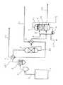
まず、第1例を説明する。図1は、本例のガス精製装置における主に前処理部の構成を示す図であり、図2は同装置における脱硫部及び石膏回収部の構成を示す図である。
【0024】
まず、前処理部の構成及び基本動作について説明する。図1に示すように、ガス化炉1では、例えば石炭が空気をガス化剤としてガス化され、一酸化炭素及び水素を主成分とした生成ガスAが発生する。
このように石炭を原料とし空気をガス化剤としてなる生成ガスAには、通常、1000〜1500ppm程度のH2S(硫黄化合物)と、100ppm程度のCOS(硫黄化合物)とが含有され、さらに、100〜1500ppm程度のNH3(窒素化合物)と、100ppm程度のHCl(塩素化合物)が含有されている。
【0025】
また生成ガスAは、炉出口直後においては通常1000℃〜1300℃であるが、通常炉出口側に設けられたスチームヒータ(図示省略)により熱回収されて例えば420℃程度に冷却され、その圧力は例えば26ata程度である。
この生成ガスAは、まずサイクロン2とポーラスフィルタ3に順次導入され、比較的大径な粉塵と微細な粉塵とがそれぞれ分離除去される構成となっている。
【0026】
ポーラスフィルタ3の後流には、COSをH2Sに変換する触媒が装填された変換器5が設けられ、生成ガスA1中のCOSのほとんどがここでH2Sに変換される。
なお、この場合の変換器5の触媒としては、例えば酸化チタン単体よりなるもので、少なくとも特公昭63−11053号公報に示されたような添加剤(Li、Na、K、Cs、Mg、Ca、Ba、Zn、Cd、Sn、Pb)を含まない触媒を使用するのが好ましい。
【0027】
というのは、発明者らの研究によれば、このような触媒であると、ハロゲン化物などの不純物がガス中に存在していても、触媒の活性が害されないことが判明しているからである。なお、その要因は必ずしも明らかになっていないが、上述のような添加剤はハロゲン化物などの不純物と親和力が強く、このような不純物がガス中に存在する場合には、却って触媒としての能力を低下させるものと考えられる。例えば、触媒中のアルカリ金属の水酸化物(例えば、KOH)が塩化水素と反応してハロゲン化物(例えば、KCl)になると、別の物質になるのであり、化学的性質が変るため、触媒としての能力が低下すると考えられる。
【0028】
またこの変換器5の後流には、熱交換器6が設けられ、変換器5から導出されたガスA2の熱によって浄化された後のガスA4が加熱される構成となっている。なおガスA2は、この熱交換器6で逆に熱を奪われて、この場合177℃程度まで冷却される。
【0029】
そして、熱交換器6の後流には、ガスA2を後述の脱硫塔21に導入する前に、洗浄液Bに気液接触させる洗浄塔7が設置されている。
洗浄塔7は、この場合いわゆる充填式の気液接触塔であり、塔底部に貯留された水を主成分とする洗浄液Bが循環ポンプ8により吸上げられて、塔上部のスプレーパイプ9から噴射され、ガスA2と気液接触しつつ充填材10を経由して流下して再び塔底部に戻って循環する構成となっている。
【0030】
また洗浄塔7は、この場合いわゆる向流式のものであり、塔下部から導入されたガスA2が、流下する洗浄液Bに対向して塔内を上昇し、HClやNH3等を除去された後、塔頂部から洗浄後のガスA3として排出される。
【0031】
すなわち洗浄塔7では、脱硫塔21に導入される前の生成ガスであるガスA2が、水を主成分とする洗浄液Bに気液接触させられるため、ガスA2中に含有される溶解度の高いNH3やHClは、特にpH調整等を行わなくても相当量が洗浄液B中に吸収され、最終的には排水Cとして系外に排出される。このため、最終的に得られるガスA5は、H2Sとともに相当量のNH3やHClが吸収除去された従来にないクリーンなものとなる。
【0032】
なお、ガスA2中には通常HClよりもNH3が多量に含まれているため、なんらpH調整をしなければ、洗浄液Bはアルカリ性を示す。洗浄液Bがアルカリ性になると、NH3の吸収性能が低下するばかりか、ガスA2中に含有される弱酸性のH2Sも相当量が洗浄液B中に吸収され、排水Cに含有されることになる。硫黄化合物は排出規制が厳しく無害化処理が困難であるため、この場合には、排水Cの排水処理が大掛かりで高コストなものとなる問題が生じる。
【0033】
この問題を解決するため本例では、洗浄塔7の洗浄液B中に硫酸等の酸Eを適宜供給してpH調整する構成としており、洗浄液BのpHを例えば弱酸性以下に保持する。これにより、排水Cに含有されるH2Sの量を抑制して、面倒な排水処理を回避できる。なおこの場合でも、HClは強酸であるため、弱酸性領域であれば十分吸収可能である。
【0034】
但し、NH3をより完全に吸収除去するためには、pHを例えば強酸領域まで大きく低下させるのが好ましく、この場合にはHClの吸収性能が低下するため、HClとNH3の両者をより完全に除去するためには、主にNH3を吸収するための洗浄塔と、主にHClを吸収するための洗浄塔とを設けた、2塔式の構成とするのが好ましい。
【0035】
なおガスA3は、洗浄液Bとの接触で冷却されるため、特に冷却器を設けなくても、脱硫塔21に導入するのに好ましい温度(40℃程度)になる。
またここで、洗浄液Bの一部は、この場合循環ポンプ8の吐出側から分岐する流路により抜き出され、排水Cとして系外に排出されるようになっている。また、洗浄液Bの循環経路のいずれかには、排水Cとして或いはガス中に含まれて持去られる分を補う量の補給水Dが適宜供給可能となっている。
また、洗浄塔7の塔上部には、ガス中のミストを分離除去するミストエリミネータ11が設けられ、後流側に流出するいわゆる同伴ミストの量が低く抑えられる構成となっている。
【0036】
次に、脱硫部の構成及び動作を図2により説明する。脱硫部は、主に脱硫塔21と再生塔22とよりなる。
脱硫塔21は、前述の洗浄塔7と同様な気液接触塔であり、再生塔22の塔底部に貯留された硫化水素の吸収液Fが循環ポンプ23により吸上げられて、吸収液熱交換器24で冷却された後、塔上部のスプレーパイプ25から噴射され、ガスA3と気液接触しつつ充填材26を経由して流下する構成となっている。
【0037】
また、吸収液Fと気液接触してH2Sを除去されたガスA4(温度は42℃程度)は、ミストエリミネータ27により同伴ミストを除去された後、この脱硫塔21の塔頂部から排出され、前述の熱交換器6により加熱されて、精製処理後のガスA5となる。
なお、ガスA5の圧力は例えば25.5ata程度、その温度は300℃程度となり、またその硫黄分(H2S及びCOSの濃度)は10ppm以下となる。
【0038】
一方、再生塔22は、脱硫塔21の塔底部に貯留された吸収液Fが循環ポンプ28により吸上げられて、吸収液熱交換器24で加熱された後、塔上部のスプレーパイプ29から噴射され、塔内を上昇する吸収液Fの蒸気や吸収成分(オフガス)と接触しつつ充填材30を経由して流下する構成となっている。
【0039】
この再生塔22の塔底部の吸収液Fは、リボイラ31において水蒸気Gにより加熱され、これにより、吸収成分であるH2Sがこの再生塔22においてガス側に放散されるようになっている。そして、このH2Sを含むオフガスHは、ミストエリミネータ32においてミストを除去された後、再生塔22の頂部に設けられた還流部を経てより高濃度にH2Sを含むオフガスH1(主成分CO2)として、後述の石膏回収部に送られる。
【0040】
なおここで、再生塔22の頂部に設けられた還流部は、オフガスHが冷却器33により冷却されることにより生成され、タンク34に貯留されたオフガスHの凝縮液Iが、ポンプ35によりスプレーパイプ36から噴射されるもので、これによりオフガスH中の蒸気がより多く液化し、液中の吸収成分であるH2Sがより多く放散して、例えば体積パーセントで20%程度の高濃度のH2Sを含むオフガスH1が得られる。
【0041】
次に、石膏回収部の構成及び動作について説明する。本例の石膏回収部は、オフガスH1を空気Jと反応させて含有されるH2Sを燃焼させる燃焼炉41と、この燃焼炉41でオフガスH1が燃焼してなる燃焼ガスH2からSO2(亜硫酸ガス)等の硫黄酸化物を吸収除去して無害な排ガスH3として排出する湿式石灰石膏法による脱硫装置とを組合せたものである。
【0042】
脱硫装置は、H2Sが燃焼してなるSO2を高濃度に含む燃焼ガスH2を、内部に供給されたカルシウム化合物を含有するスラリKと気液接触させて排出する反応器42と、この反応器42内のスラリ中に酸化用空気Lを多数の微細気泡として吹込む空気供給手段(図示略)と、反応器42から抜き出されたスラリM(石膏スラリ)を固液分離する遠心分離機等の固液分離手段44とを備える。
【0043】
なお、図2において符号46で示すものは、燃焼ガスH2をSO2等の吸収に好ましい温度に冷却する冷却器である。また、固液分離手段44における固液分離により生成した分離水M3は、反応器42内のスラリを構成する水分として、この場合反応器42内に直接戻されている。
【0044】
ここで反応器42は、具体的には、例えば塔底部に酸化用空気Lが吹込まれるスラリタンクを有し、燃焼ガスH2が流通する塔上部に、スラリタンク内のスラリが噴射される充填式、スプレー式、又は液柱式等の気液接触部を備えた、スラリ循環式のいわゆる吸収塔により構成できる。或いはこの反応器42は、タンク内のスラリ中に酸化用空気Lと燃焼ガスH2の両者が吹込まれ、SO2等の吸収と酸化が全てタンク内で行われるいわゆるバブリング方式のものであってもよい。いずれにしろ反応器42では、例えば以下の反応式(1)乃至(3)で示されるような反応が進行して、主にSO2が吸収され、二水石膏が生成される。
【0045】
【化1】
SO2 +H2O → H+ +HSO3- (1)
H+ +HSO3- +1/2O2 → 2H+ +SO42- (2)
2H+ +SO42- +CaCO3 +H2O
→ CaSO4・2H2O +CO2 (3)
【0046】
なお、反応器42に供給されるスラリKは、例えば石灰石(CaCO3)等のカルシウム化合物が図示省略したスラリタンクにおいて、工業用水等と攪拌混合されてなるものであるが、カルシウム化合物は微細化した固形状態のまま直接反応器42に供給するようにしてもよいことはいうまでもない。また、石膏加熱装置45(石膏加熱工程)を設けて、固液分離手段44により得られた固形分M1(二水石膏の石膏ケーキ)を120℃〜150℃程度まで加熱して半水石膏M2としてもよい。
【0047】
また、カルシウム化合物の供給量は、吸収すべき亜硫酸ガスの量に応じて基本的に決定されるが、実際の運転では例えば反応器42内のスラリのpHや未反応石灰石濃度等を検知して、この値が吸収反応等に最適な値に保持されるように供給量を微調整するような制御をすればよい。
また酸化用空気Lは、例えば反応器42内のスラリの酸化還元電位等を検知して、必要最小限な量だけ供給するようにするのが好ましい。
【0048】
以上のように構成されたガス精製装置によれば、COS変換器5が洗浄塔7の前流側(高温側)に設けられ、洗浄塔7から出たガスA3がそのままの温度で脱硫塔21に導入されるため、図7に示す熱交換器103、加熱器104、及び冷却器106に相当する機器が全く不要になり、加熱器104で必要な熱エネルギーや冷却器106の冷媒も不要になる。
【0049】
すなわち、本例の要部構成を図7と同様に図示すれば、図5(a)のようになり、熱機器として熱交換器6のみが設けられた極めて簡素で運転コストの低い装置構成になるのが分る。この場合、熱交換器6におけるガス入口出口の温度条件は、図7に示す熱交換器101と同様であり、熱交換器6の伝熱面積も2262m2でよいため、本例の場合の熱機器のトータルの伝熱面積は2262m2となって、図7の構成に比較して極めて小さくなる。
【0050】
また、図7においてCOS変換器105に導入されるガスQ2に比較して、本例のCOS変換器5に導入されるガスA1は水分を多く含むので、図7に示すような蒸気QWを特に供給する必要もない。
したがって本例によれば、装置が極めて小型になり、運転コストも著しく低減できる。
【0051】
しかも、洗浄塔や脱硫塔の運転条件は変らないため、精製装置としての性能(硫黄化合物やその他不純物の除去率)は、図7に示す構成と同等かそれ以上になる。
特に、COS変換器5におけるガス温度は、420℃程度と極めて高いため、COSの変換率が極めて高くなり、結果としてCOSの除去率が図7に示すような構成に比較して著しく高くなる。
【0052】
例えば、COS変換器5の触媒として前述したような酸化チタンの単体を使用した場合には、COSの変換率と温度条件との関係が図6の実線及び黒丸印に示すようになるという実験結果が得られており、420℃の場合には、95%程度の極めて高い変換率が得られる。
【0053】
また、例えば特公昭63−11053号公報に開示されたような従来の一般的なCOS変換触媒の場合には、図6の三角印に示すようになるという実験結果が得られており、特に温度が低い程、極端に性能が落ちることが分っている。このため、COSの変換率向上という点では、いずれの触媒を使用しても、COS変換器5の温度条件が極めて高くできる本例の構成が有効であることが分る。
【0054】
なお図6のデータは、COS変換触媒の活性を害するハロゲン化物などの不純物がガス中に存在しない場合のデータであるが、前述したように例えば酸化チタン単体の場合(図6の実線及び黒丸印)には、このような不純物が存在してもこの性能が維持される。
【0055】
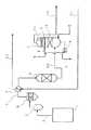
第2例
次に、第2例を説明する。図3は、本例のガス精製装置における主に前処理部の構成を示す図である。また、本例の要部構成を図7と同様に図示すると、図5(b)のようになる。なお、第1例と同様の要素には同符号を付して、重複する説明を省略する。
本例は、第1例の構成に加えてCOS変換器5の前流側(ポーラスフィルタ3の後流側)に熱交換器4を設けたもので、脱硫塔21で処理された後のガスA4を加熱するための熱を、COS変換器5の後流側と前流側のガスから回収する構成としたものである。
【0056】
すなわち熱交換器4は、ポーラスフィルタ3から導出されたガスA1の熱により精製された後のガスA4を加熱するもので、COS変換器5の後流側のガスA2の熱で同じくガスA4を加熱する熱交換器6との組合せで、最終的にガスA4を前述のガスタービン等に送る温度(300℃程度)まで加熱する。
【0057】
この場合、ガスA1はこの熱交換器4において熱を奪われて、例えば250℃程度まで冷却されるので、COS変換器5の温度条件も250℃程度まで低下することになる。しかし、COS変換器5の温度条件が150℃程度であり、しかもこの温度条件を実現するために加熱器等を別個に設けている図7の構成に比較すれば、やはり装置の小型化や運転コストの低減が図れるとともに、COSの変換率の向上が図れる。
【0058】
またこの場合、熱交換器4の出口ガス温度を250℃程度の高温とすることによって、アンモニアと塩化水素が結合してなる塩化アンモニウムの固体粒子生成が抑制でき、COS変換器5での触媒上に固体粒子が付着するのを確実に防止できる。
【0059】
なおこの場合、例えばCOS変換触媒として前述したような酸化チタン単体よりなる触媒を使用した場合には、図6から分るように90%程度の高い変換率が実現できる。
またこの場合、熱交換器4として必要な伝熱面積は1626m2、熱交換器6として必要な伝熱面積は636m2であり、熱機器のトータルの伝熱面積はやはり2262m2となって、図7の構成に比較して極めて小さくなる。
【0060】
第3例
次に、第3例を説明する。図4は、本例のガス精製装置における主に前処理部の構成を示す図である。また、本例の要部構成を図7と同様に図示すると、図5(c)のようになる。なお、第1例及び第2例と同様の要素には同符号を付して、重複する説明を省略する。
本例は、COS変換器5の後流側の熱交換器6を削除して、COS変換器5の前流側の熱交換器4を設けたもので、脱硫塔21で処理された後のガスA4を加熱するための熱を、COS変換器5の前流側のガスのみから回収する構成としたものである。
【0061】
すなわち、この場合の熱交換器4は、ポーラスフィルタ3から導出されたガスA1の熱により精製された後のガスA4を加熱し、ガスA4の温度を前述のガスタービン等に送る温度(300℃程度)まで加熱する。
【0062】
なおこの場合、ガスA1はこの熱交換器4において熱を奪われて、177℃程度まで冷却されるので、COS変換器5の温度条件も177℃程度まで低下することになる。しかし、COS変換器5の温度条件が150℃程度であり、しかもこの温度条件を実現するために加熱器等を別個に設けている図7の構成に比較すれば、やはり装置の小型化や運転コストの低減が図れるとともに、COSの変換率の向上が図れる。
【0063】
なおこの場合、例えばCOS変換触媒として前述したような酸化チタン単体よりなる触媒を使用した場合には、図6から分るように85%程度の比較的高い変換率が実現できる。
またこの場合、熱交換器4として必要な伝熱面積は2262m2であり、熱機器のトータルの伝熱面積はやはり2262m2となって、図7の構成に比較して極めて小さくなる。
【0064】
なお本例は、アンモニアと塩化水素が結合してなる塩化アンモニウムの固体粒子生成が少ない場合に特に有効であるが、塩化アンモニウムの固体粒子生成が相当量ある場合でも、COS変換器5の触媒を例えばハニカム型に成型して固体粒子が付着目詰りし難い構造とすれば、固体粒子の付着の問題に対処できる。
【0065】
なお、本発明は上記形態例に限られず各種の態様がありうる。例えば、必要に応じて洗浄塔の洗浄液を冷却する冷却器を設けてガス温度を十分に下げるとともに、洗浄塔の後流側にポーラスフィルタなどの除塵手段を設けて、生成ガスの冷却により発生する塩化アンモニウムのヒューム(サブミクロンの固体粒子)をこの除塵手段により除去するようにしてもよい。
【0066】
なお、塩化アンモニウムのヒュームは、洗浄塔での気液接触や脱硫塔での吸収処理では除去が困難であり、ヒューム状で通過するとガスタービンの材料腐食トラブルを引き起こしたり、燃焼によって熱分解して有害物(窒素化合物や塩素化合物等)として大気中に排出されるため、塩化水素やアンモニアなどの不純物と同様になるべく前流側で除去することが好ましい物質である。
【0067】
また本発明は、石灰石膏法による脱硫処理(除去した硫化水素から石膏を回収する態様)を採用せず、脱硫塔において吸収された硫黄分(硫化水素)から硫黄単体を回収する態様でもよいことはいうまでもない。
【0068】
【発明の効果】
請求項1記載のガス精製装置は、生成ガスを脱硫塔に導入する前に洗浄液に気液接触させて洗浄する洗浄塔を備えるとともに、この洗浄塔の前流において生成ガス中の硫化カルボニルを硫化水素に変換する変換器を備える。
このため、最終的に得られるガスは、硫化カルボニル及び硫化水素を含む硫黄化合物とともに、相当量の塩素化合物などの不純物が吸収除去された従来にないクリーンなものとなり、硫黄化合物や塩素化合物などの不純物がガス中に残留することによる前述の問題点が解消される。
【0069】
しかも本発明では、硫化カルボニルの変換器を洗浄塔の前流側(高温側)に設けているため、洗浄塔の後流側に設ける場合と比較して、洗浄塔から出たガスがそのままの温度で脱硫塔に導入されることになり、図7に示す熱交換器103、加熱器104、及び冷却器106に相当する機器が全く不要になり、加熱器104で必要な熱エネルギーや冷却器106の冷媒(工業用水等)も不要になる。
【0070】
すなわち、本装置の要部構成を図7と同様に図示すれば、例えば図5(a),(b),(c)のようになり、熱機器として熱交換器6又は熱交換器4のみが設けられた極めて簡素で運転コストの低い装置構成になるのが分る。この場合、洗浄塔や脱硫塔のガス入口出口の温度条件を図7に示す場合と同じとすれば、熱交換器のトータルの伝熱面積は、いずれの場合も2262m2であり、図7の構成(トータルの伝熱面積は6629m2)に比較して極めて小さくなる。
【0071】
また、図7においてCOS変換器105に導入されるガスQ2に比較して、本発明のCOS変換器に導入されるガスA1は水分を多く含むので、図7に示すような蒸気QWを特に供給する必要もない。
したがって本発明によれば、装置が極めて小型になり、運転コストも著しく低減できる。
【0072】
しかも、洗浄塔や脱硫塔の運転条件は変らないため、精製装置としての性能(硫黄化合物やその他不純物の除去率)は、図7に示す構成と同等かそれ以上になる。
【0073】
特に請求項3記載のように、脱硫塔で処理された後の生成ガスを加熱するための熱を、COS変換器の後流側の生成ガスから回収し、COS変換器の前流側の生成ガスからは回収しない構成とした場合(図5(a)に示すような態様の場合)には、COS変換器におけるガス温度は、処理前のガス温度そのものであり例えば420℃程度と極めて高くなるため、COSの変換率が極めて高くなり、結果としてCOSの除去率が図7に示すような構成に比較して著しく高くなる。またこの場合、COS変換器に導入されるガス温度が420℃程度の高温とされることによって、アンモニアと塩化水素が結合してなる塩化アンモニウムの固体粒子生成が抑制でき、COS変換器での触媒上に固体粒子が付着するのを確実に防止できる。
【0074】
また請求項4記載のように、脱硫塔で処理された後の生成ガスを加熱するための熱を、COS変換器の後流側と前流側の生成ガスから回収する構成とした場合(図5(b)に示すような態様の場合)には、COS変換器におけるガス温度は、処理前のガス温度が比較的若干量低下したものとなり例えば250℃程度と高くなるため、やはりCOSの変換率が格段に高くなり、結果としてCOSの除去率が図7に示すような構成に比較して格段に高くなる。またこの場合、COS変換器に導入されるガス温度が250℃程度の高温とされることによって、アンモニアと塩化水素が結合してなる塩化アンモニウムの固体粒子生成が抑制でき、COS変換器での触媒上に固体粒子が付着するのを確実に防止できる。
【0075】
さらに、請求項2記載のガス精製装置では、COS変換器の触媒として、酸化チタンよりなり、生成ガス中の不純物と親和力の強い添加剤を含まない触媒を使用した。
このため、生成ガス中の不純物により前記触媒の活性が害されるという不具合が解消され、本発明のように上記不純物を除去する洗浄塔の前にCOS変換器を配置した場合でも、触媒の機能が長期間に渡って高く発揮され、実用性がより向上する。
【図面の簡単な説明】
【図1】本発明の第1例である精製装置の主に前処理部の構成を示す図である。
【図2】同精製装置における脱硫部及び石膏回収部の構成を示す図である。
【図3】本発明の第2例である精製装置の主に前処理部の構成を示す図である。
【図4】本発明の第3例である精製装置の主に前処理部の構成を示す図である。
【図5】本発明の各例の要部構成を示す図である。
【図6】温度条件をパラメータとした場合のCOS変換率のデータを示す図である。
【図7】COS変換器を洗浄塔の後流に配置した精製装置の要部構成を示す図である。
【符号の説明】
4,6 熱交換器
5 変換器
7 洗浄塔
21 脱硫塔
A,A1〜A5 生成ガス
B 洗浄液
F 吸収液[0001]
BACKGROUND OF THE INVENTION
The present invention relates to a wet purification apparatus for a product gas such as a coal gasification process, and in particular, it is possible to easily remove sulfur compounds and other impurities in the gas, and the produced gas for this removal treatment. The present invention relates to a gas purification apparatus in which the capacity of a heat exchanger that cools and reheats can be significantly reduced.
[0002]
[Prior art]
In recent years, fuel resources have been diversified due to the depletion of petroleum resources and rising prices, and development of technologies for using coal and heavy oil has been promoted. One of these is the gasification of coal and heavy oil to generate electricity. The technology for fuel and synthetic raw materials is attracting attention. In addition, power generation using gasification gas is more efficient than conventional thermal power generation using coal or oil, and thus has attracted attention from the viewpoint of effective use of limited resources.
[0003]
However, this gasification product gas contains several hundred to several thousand ppm of sulfur compounds (mainly hydrogen sulfide) for preventing pollution or preventing corrosion of downstream equipment (for example, a gas turbine). Therefore, it is necessary to remove. As this removal method, for example, as shown in Japanese Patent Application Laid-Open No. 7-48584, a wet gas purification technique in which a gas is brought into gas-liquid contact with an absorbing liquid is known.
[0004]
In addition, as a sulfur compound contained in gasification product gas, H2In addition to S (hydrogen sulfide), about 100 ppm of COS (carbonyl sulfide) is contained, but this cannot be removed by the absorbing solution.
For this reason, in order to remove this COS by wet gas purification, the COS is previously hydrolyzed by hydrolysis reaction in the upstream of the desulfurization tower in which the gas-liquid contact between the absorption liquid and the gas occurs.2It is necessary to convert to S. Conventionally, as a catalyst for this conversion, for example, as shown in Japanese Patent Publication No. 63-11053 and Japanese Patent Laid-Open No. 1-222397, an additive such as Li or Na is added based on titanium oxide. Things are known.
[0005]
[Problems to be solved by the invention]
By the way, in the conventional gas purification technology, chlorine compounds (HCl) and nitrogen compounds (NH) contained in the product gas.ThreeNo particular consideration was given to harmful impurities such as), and improvements were desired.
That is, in general, for a product gas such as a coal gasification process, NH of about 100 to 1500 ppm is used.ThreeFor example, since about 100 ppm of HCl is contained, it is necessary to remove these for further cleaning.
[0006]
Of these, HCl, which is a chlorine compound, is a strong acid and corrosive to stainless steel, and it is necessary to remove it as much as possible from the viewpoint of protecting equipment materials, and the generated gas is a gas. In order to reduce the amount of chlorine compounds discharged into the atmosphere as contained in the flue gas that is burned by a turbine or the like, it is necessary to remove them.
[0007]
In addition, ammonia, which is a nitrogen compound, is hardly removed by gas-liquid contact treatment in a desulfurization tower using an absorption liquid (alkaline) generally made of an amine compound, and burns in a gas turbine or the like to form harmful nitrogen oxides. This is a problem because it increases the load of a denitration apparatus generally provided on the downstream side of a turbine or the like.
[0008]
Therefore, the applicant proposed a technique for removing the impurities by cleaning the gas by bringing the produced gas (hereinafter, the produced gas may be simply referred to as gas) into the washing liquid in the gas-liquid contact in the upstream of the desulfurization tower. However, in this case, there are problems with the positional relationship between the cleaning tower for performing the cleaning and the COS converter for converting the COS, and the equipment configuration such as a heat exchanger for effectively using the heat of the generated gas. Become.
[0009]
That is, according to the knowledge of the inventors, impurities such as halides in a gas typified by HCl can cause COS to H.2In order to avoid such a decrease in activity, it is known that the washing tower is provided upstream of the COS converter, and the impurities are washed and removed in advance. The configuration was considered preferred.
[0010]
However, the performance (conversion rate) of the COS converter tends to decrease as the gas temperature decreases. In this case, in order to bring the performance to a practical level, the COS converter was cooled by contact with the cleaning liquid in the cleaning tower. It is necessary to reheat the gas to at least about 150 ° C. Moreover, in order to ensure the performance in the desulfurization tower, it is preferable to lower the temperature of the gas leaving the COS converter and entering the desulfurization tower to about 40 ° C.
[0011]
Furthermore, in order to maintain the high-temperature efficiency by maintaining the processed gas sent to the gas turbine or the like at a higher temperature, the heat was recovered from the high-temperature gas before being introduced into the washing tower, and then exited the desulfurization tower. It is also necessary to heat the treated gas.
For this reason, in the case of the configuration in which the washing tower is arranged upstream of the COS converter, the equipment configuration becomes a complicated configuration as shown in FIG. 7, for example, and the equipment is increased in size and cost. It was a big problem.
[0012]
In the apparatus configuration of FIG. 7, what is denoted by reference numeral Q1 is removed from the gasification furnace (not shown), recovered by heat with a steam heater (not shown), and then removed with a porous filter or the like (not shown). This is a product gas before purification treatment, and its temperature is about 420 ° C.
The product gas Q1 is first introduced into the
[0013]
Next, the product gas Q1 is introduced into the
Next, the gas Q2 exiting the
[0014]
Next, the gas Q2 exiting the
Next, the gas Q3 exiting the
[0015]
Next, in the
Next, the gas Q4 exiting the
[0016]
In the configuration shown in FIG. 7, the heat transfer areas of the two
[0017]
In addition, heat energy for heating by the
Moreover, although the apparatus configuration is large and expensive, the gas temperature in the COS converter is only about 150 ° C. as described above, so the COS conversion efficiency cannot be so high.
[0018]
Therefore, the present invention has an object to provide a gas purifier capable of realizing more complete absorption of sulfur compounds in gas and removing impurities such as chlorine compounds and nitrogen compounds with a small equipment configuration and at low cost. It is said.
[0019]
[Means for Solving the Problems]
In order to achieve the above object, a gas purifier according to
A desulfurization tower that absorbs and removes at least hydrogen sulfide contained in the product gas by bringing the product gas into gas-liquid contact with an absorption liquid;
A cleaning tower for cleaning by bringing the product gas into gas-liquid contact with the cleaning liquid before introducing the generated gas into the desulfurization tower;
And a converter for converting carbonyl sulfide in the product gas into hydrogen sulfide in the upstream of the washing tower.
[0020]
The gas purifier according to
[0021]
Further, the gas purification apparatus according to
[0022]
Further, the gas purification apparatus according to
[0023]
DETAILED DESCRIPTION OF THE INVENTION
Hereinafter, embodiments of the present invention will be described with reference to the drawings.
First example
First, a first example will be described. FIG. 1 is a diagram mainly showing a configuration of a pretreatment unit in the gas purification apparatus of this example, and FIG. 2 is a diagram showing a configuration of a desulfurization unit and a gypsum recovery unit in the same device.
[0024]
First, the configuration and basic operation of the preprocessing unit will be described. As shown in FIG. 1, in the
In this way, the generated gas A using coal as a raw material and air as a gasifying agent is usually about 1000 to 1500 ppm of H.2S (sulfur compound) and about 100 ppm of COS (sulfur compound) are contained, and furthermore, about 100 to 1500 ppm of NH.Three(Nitrogen compound) and about 100 ppm of HCl (chlorine compound) are contained.
[0025]
The product gas A is usually 1000 ° C. to 1300 ° C. immediately after the furnace outlet, but is usually recovered by a steam heater (not shown) provided on the furnace outlet side and cooled to about 420 ° C., for example. Is about 26 data, for example.
First, the generated gas A is sequentially introduced into the
[0026]
In the downstream of the
In this case, the catalyst of the
[0027]
This is because, according to studies by the inventors, it has been found that such a catalyst does not impair the activity of the catalyst even if impurities such as halides are present in the gas. is there. In addition, although the factor is not necessarily clarified, the additive as described above has a strong affinity with impurities such as halides, and when such impurities are present in the gas, on the contrary, the ability as a catalyst is reduced. It is thought to decrease. For example, when an alkali metal hydroxide (for example, KOH) in a catalyst reacts with hydrogen chloride to become a halide (for example, KCl), it becomes a different substance, and its chemical properties change. It is thought that the ability of
[0028]
Further, a
[0029]
A cleaning
The
[0030]
In this case, the
[0031]
That is, in the
[0032]
The gas A2 is usually NH rather than HCl.ThreeIs contained in a large amount, the cleaning solution B exhibits alkalinity without any pH adjustment. When cleaning liquid B becomes alkaline, NHThreeAs well as the absorption performance of the gas, the weakly acidic H contained in the gas A22A considerable amount of S is also absorbed in the cleaning liquid B and contained in the waste water C. Since sulfur compounds are strictly regulated and difficult to be detoxified, in this case, there is a problem that wastewater treatment of wastewater C is large and expensive.
[0033]
In order to solve this problem, in this example, an acid E such as sulfuric acid is appropriately supplied into the cleaning liquid B of the cleaning
[0034]
However, NHThreeIn order to absorb and remove more completely, it is preferable to greatly reduce the pH to, for example, the strong acid region. In this case, since the absorption performance of HCl is lowered, HCl and NHThreeIn order to remove both of them more completely, mainly NHThreeIt is preferable to adopt a two-column configuration in which a washing tower for absorbing water and a washing tower for mainly absorbing HCl are provided.
[0035]
Since the gas A3 is cooled by contact with the cleaning liquid B, the temperature becomes a preferable temperature (about 40 ° C.) for introduction into the
In this case, a part of the cleaning liquid B is extracted through a flow path branched from the discharge side of the
A
[0036]
Next, the configuration and operation of the desulfurization unit will be described with reference to FIG. The desulfurization section mainly includes a
The
[0037]
In addition, gas-liquid contact with the absorbing liquid F causes H2The gas A4 (temperature is about 42 ° C.) from which S has been removed is removed from the top of the
The pressure of the gas A5 is, for example, about 25.5 at, the temperature is about 300 ° C., and the sulfur content (H2The concentration of S and COS is 10 ppm or less.
[0038]
On the other hand, in the
[0039]
The absorption liquid F at the bottom of the
[0040]
Here, the reflux section provided at the top of the
[0041]
Next, the configuration and operation of the gypsum recovery unit will be described. The gypsum recovery part of this example is an H gas contained by reacting off-gas H1 with air J.2A combustion furnace 41 for burning S, and a combustion gas H2 formed by burning off-gas H1 in the combustion furnace 41 from SO2This is a combination of a desulfurization apparatus using a wet lime gypsum method that absorbs and removes sulfur oxides such as (sulfurous acid gas) and discharges it as harmless exhaust gas H3.
[0042]
Desulfurization equipment is H2SO formed by burning S2The
[0043]
In addition, what is shown with the code |
[0044]
Specifically, the
[0045]
[Chemical 1]
SO2 + H2O → H+ + HSOThree- (1)
H+ + HSOThree- + 1 / 2O2 → 2H+ + SOFour2- (2)
2H+ + SOFour2- + CaCOThree + H2O
→ CaSOFour・ 2H2O + CO2 (3)
[0046]
The slurry K supplied to the
[0047]
The supply amount of the calcium compound is basically determined according to the amount of sulfurous acid gas to be absorbed. In actual operation, for example, the pH of the slurry in the
The oxidizing air L is preferably supplied by detecting the oxidation-reduction potential of the slurry in the
[0048]
According to the gas purification apparatus configured as described above, the
[0049]
That is, if the main part structure of this example is illustrated similarly to FIG. 7, it becomes as shown in FIG. 5 (a), and it is an extremely simple and low-operating device structure in which only the
[0050]
In addition, compared with the gas Q2 introduced into the
Therefore, according to this example, the apparatus becomes extremely small, and the operating cost can be significantly reduced.
[0051]
In addition, since the operating conditions of the washing tower and desulfurization tower do not change, the performance as a refining device (removal rate of sulfur compounds and other impurities) is equal to or higher than the configuration shown in FIG.
In particular, since the gas temperature in the
[0052]
For example, when a single titanium oxide as described above is used as the catalyst of the
[0053]
Further, for example, in the case of a conventional general COS conversion catalyst as disclosed in Japanese Patent Publication No. 63-11053, an experimental result is obtained as shown by a triangle mark in FIG. It has been found that the lower the value, the lower the performance. For this reason, in terms of improving the conversion rate of COS, it can be seen that the configuration of this example is effective in that the temperature condition of the
[0054]
The data in FIG. 6 is data in the case where impurities such as halides that impair the activity of the COS conversion catalyst are not present in the gas. As described above, for example, in the case of titanium oxide alone (solid line and black circles in FIG. 6). ) Maintains this performance even in the presence of such impurities.
[0055]
Second example
Next, a second example will be described. FIG. 3 is a diagram mainly showing the configuration of the pretreatment section in the gas purification apparatus of this example. Moreover, when the principal part structure of this example is illustrated similarly to FIG. 7, it will become like FIG.5 (b). In addition, the same code | symbol is attached | subjected to the element similar to a 1st example, and the overlapping description is abbreviate | omitted.
In this example, in addition to the configuration of the first example, the
[0056]
That is, the
[0057]
In this case, since the gas A1 is deprived of heat in the
[0058]
Further, in this case, by setting the outlet gas temperature of the
[0059]
In this case, for example, when a catalyst made of a single titanium oxide as described above is used as the COS conversion catalyst, a high conversion rate of about 90% can be realized as can be seen from FIG.
In this case, the heat transfer area required for the
[0060]
Third example
Next, a third example will be described. FIG. 4 is a diagram mainly showing the configuration of the pretreatment unit in the gas purification apparatus of this example. Moreover, if the principal part structure of this example is illustrated similarly to FIG. 7, it will become like FIG.5 (c). In addition, the same code | symbol is attached | subjected to the element similar to a 1st example and a 2nd example, and the overlapping description is abbreviate | omitted.
In this example, the
[0061]
That is, the
[0062]
In this case, since the gas A1 is deprived of heat in the
[0063]
In this case, for example, when a catalyst composed of a single titanium oxide as described above is used as the COS conversion catalyst, a relatively high conversion rate of about 85% can be realized as shown in FIG.
In this case, the heat transfer area necessary for the
[0064]
This example is particularly effective when the production of solid ammonium chloride particles formed by combining ammonia and hydrogen chloride is small. However, even when there is a substantial amount of solid ammonium chloride particles, the catalyst of the
[0065]
In addition, this invention is not restricted to the said example of a form, There can exist various aspects. For example, if necessary, a cooler for cooling the cleaning liquid of the cleaning tower is provided to sufficiently lower the gas temperature, and dust removal means such as a porous filter is provided on the downstream side of the cleaning tower, and generated by cooling the generated gas. Ammonium chloride fumes (submicron solid particles) may be removed by the dust removing means.
[0066]
Ammonium chloride fumes are difficult to remove by gas-liquid contact in the washing tower or absorption treatment in the desulfurization tower. If they pass in the form of fumes, they cause gas turbine material corrosion troubles, or they are thermally decomposed by combustion. Since it is discharged into the atmosphere as harmful substances (nitrogen compounds, chlorine compounds, etc.), it is a preferable substance to be removed on the upstream side as much as possible such as impurities such as hydrogen chloride and ammonia.
[0067]
In addition, the present invention does not employ a desulfurization process (an aspect in which gypsum is recovered from the removed hydrogen sulfide) by the lime gypsum method, and may be an aspect in which simple sulfur is recovered from the sulfur content (hydrogen sulfide) absorbed in the desulfurization tower. Needless to say.
[0068]
【The invention's effect】
The gas purification apparatus according to
For this reason, the gas finally obtained is an unprecedented clean substance in which impurities such as a large amount of chlorine compounds are absorbed and removed together with sulfur compounds including carbonyl sulfide and hydrogen sulfide, and the sulfur compounds and chlorine compounds, etc. The aforementioned problems due to impurities remaining in the gas are eliminated.
[0069]
Moreover, in the present invention, since the carbonyl sulfide converter is provided on the upstream side (high temperature side) of the washing tower, the gas emitted from the washing tower remains as compared with the case where it is provided on the downstream side of the washing tower. The
[0070]
That is, if the principal part structure of this apparatus is illustrated similarly to FIG. 7, it will become like FIG. 5 (a), (b), (c), for example, and only the
[0071]
In addition, compared with the gas Q2 introduced into the
Therefore, according to the present invention, the apparatus becomes extremely small, and the operating cost can be significantly reduced.
[0072]
In addition, since the operating conditions of the washing tower and desulfurization tower do not change, the performance as a refining device (removal rate of sulfur compounds and other impurities) is equal to or higher than the configuration shown in FIG.
[0073]
In particular, the heat for heating the product gas after being treated in the desulfurization tower is recovered from the product gas on the downstream side of the COS converter, and generated on the upstream side of the COS converter. In a case where the gas is not recovered from the gas (in the case shown in FIG. 5 (a)), the gas temperature in the COS converter is the gas temperature before the treatment itself, and becomes extremely high, for example, about 420 ° C. Therefore, the COS conversion rate becomes extremely high, and as a result, the COS removal rate becomes remarkably high as compared with the configuration shown in FIG. In this case, the temperature of the gas introduced into the COS converter is set to a high temperature of about 420 ° C., so that generation of solid particles of ammonium chloride formed by combining ammonia and hydrogen chloride can be suppressed, and the catalyst in the COS converter can be suppressed. Solid particles can be reliably prevented from adhering to the top.
[0074]
Further, as described in
[0075]
Furthermore, in the gas purification apparatus according to the second aspect, as the catalyst for the COS converter, a catalyst which is made of titanium oxide and does not contain an additive having a strong affinity for impurities in the generated gas is used.
For this reason, the problem of impairing the activity of the catalyst due to impurities in the product gas is solved, and even when a COS converter is arranged in front of the washing tower for removing the impurities as in the present invention, the function of the catalyst is maintained. It is highly demonstrated over a long period of time, and the practicality is further improved.
[Brief description of the drawings]
FIG. 1 is a diagram mainly showing a configuration of a pretreatment unit of a purification apparatus as a first example of the present invention.
FIG. 2 is a diagram showing a configuration of a desulfurization unit and a gypsum recovery unit in the purification apparatus.
FIG. 3 is a diagram mainly showing a configuration of a pretreatment unit of a purification apparatus as a second example of the present invention.
FIG. 4 is a diagram mainly showing a configuration of a pretreatment unit of a purification apparatus as a third example of the present invention.
FIG. 5 is a diagram showing a main configuration of each example of the present invention.
FIG. 6 is a diagram showing COS conversion rate data when temperature conditions are used as parameters.
FIG. 7 is a diagram showing a main configuration of a refining device in which a COS converter is arranged in the downstream of a washing tower.
[Explanation of symbols]
4,6 heat exchanger
5 Converter
7 Washing tower
21 Desulfurization tower
A, A1-A5 Product gas
B Cleaning liquid
F absorbent
Claims (4)
Translated fromJapanesePriority Applications (2)
| Application Number | Priority Date | Filing Date | Title |
|---|---|---|---|
| JP24972097AJP4227676B2 (en) | 1997-08-29 | 1997-08-29 | Gas purification equipment |
| CN98116497ACN1092228C (en) | 1997-08-29 | 1998-08-28 | Coal gas purifier |
Applications Claiming Priority (1)
| Application Number | Priority Date | Filing Date | Title |
|---|---|---|---|
| JP24972097AJP4227676B2 (en) | 1997-08-29 | 1997-08-29 | Gas purification equipment |
Publications (2)
| Publication Number | Publication Date |
|---|---|
| JPH1180760A JPH1180760A (en) | 1999-03-26 |
| JP4227676B2true JP4227676B2 (en) | 2009-02-18 |
Family
ID=17197203
Family Applications (1)
| Application Number | Title | Priority Date | Filing Date |
|---|---|---|---|
| JP24972097AExpired - LifetimeJP4227676B2 (en) | 1997-08-29 | 1997-08-29 | Gas purification equipment |
Country Status (2)
| Country | Link |
|---|---|
| JP (1) | JP4227676B2 (en) |
| CN (1) | CN1092228C (en) |
Cited By (2)
| Publication number | Priority date | Publication date | Assignee | Title |
|---|---|---|---|---|
| WO2019177012A1 (en) | 2018-03-14 | 2019-09-19 | 三菱重工エンジニアリング株式会社 | Gas purifier |
| US10518210B2 (en) | 2016-11-22 | 2019-12-31 | Mitsubishi Heavy Industries Engineering, Ltd. | Gas clean-up unit and gas purification method |
Families Citing this family (15)
| Publication number | Priority date | Publication date | Assignee | Title |
|---|---|---|---|---|
| JP4658350B2 (en)* | 2001-02-22 | 2011-03-23 | 電源開発株式会社 | Method and apparatus for reducing sulfur compounds |
| CA2569998C (en) | 2004-10-25 | 2007-05-15 | Oldcastle Building Products Canada, Inc. | An artificial flagstone for providing a surface with a natural random look |
| JP4594886B2 (en)* | 2006-03-16 | 2010-12-08 | メタウォーター株式会社 | Method for removing carbonyl sulfide and cyanide in fuel gas |
| US20090173081A1 (en)* | 2008-01-07 | 2009-07-09 | Paul Steven Wallace | Method and apparatus to facilitate substitute natural gas production |
| US8528343B2 (en)* | 2008-01-07 | 2013-09-10 | General Electric Company | Method and apparatus to facilitate substitute natural gas production |
| US7927513B1 (en)* | 2009-10-27 | 2011-04-19 | Coskata, Inc. | Method of treating a hot syngas stream for conversion to chemical products by removing ammonia and COS |
| CN101890286B (en)* | 2010-08-04 | 2012-11-14 | 姜辉 | Method and device for removing hydrogen sulfide from gas by using suspension of ferric oxide powder |
| CA2873070C (en) | 2012-06-18 | 2015-08-18 | Oldcastle Building Products Canada Inc. | Dual-unit paving system |
| US9315950B2 (en) | 2012-10-19 | 2016-04-19 | Oldcastle Architectural, Inc. | Paving stones |
| CN103113927A (en)* | 2013-03-15 | 2013-05-22 | 金川集团股份有限公司 | Method of improving utilization rate of heat in desulfurizing process of raw gas |
| US20150136653A1 (en)* | 2013-11-19 | 2015-05-21 | Uop Llc | Process for pyrolysis and gasification of a coal feed |
| CN104059695B (en)* | 2014-06-19 | 2016-04-27 | 衡阳华菱钢管有限公司 | Pressure Swing Adsorption blast furnace gas device and Pressure Swing Adsorption blast furnace gas method |
| JP6925936B2 (en)* | 2017-10-31 | 2021-08-25 | 三菱重工エンジニアリング株式会社 | Acid gas removal device and acid gas removal method |
| JP7325948B2 (en) | 2018-11-21 | 2023-08-15 | 三菱重工業株式会社 | Pulverized Coal Drying System for Pulverized Coal Mill, Pulverized Coal Drying Method Therefor, Pulverized Coal Drying Program, Pulverized Coal Mill, Combined Gasification Combined Cycle System |
| CN114588734B (en)* | 2022-01-28 | 2023-09-29 | 杨光华 | Method for purifying yellow phosphorus tail gas of electric furnace |
Family Cites Families (1)
| Publication number | Priority date | Publication date | Assignee | Title |
|---|---|---|---|---|
| CN1019663B (en)* | 1990-09-04 | 1992-12-30 | 湖南省化肥工业公司 | Process for refining raw gas of synthetic ammonia |
- 1997
- 1997-08-29JPJP24972097Apatent/JP4227676B2/ennot_activeExpired - Lifetime
- 1998
- 1998-08-28CNCN98116497Apatent/CN1092228C/ennot_activeExpired - Fee Related
Cited By (3)
| Publication number | Priority date | Publication date | Assignee | Title |
|---|---|---|---|---|
| US10518210B2 (en) | 2016-11-22 | 2019-12-31 | Mitsubishi Heavy Industries Engineering, Ltd. | Gas clean-up unit and gas purification method |
| WO2019177012A1 (en) | 2018-03-14 | 2019-09-19 | 三菱重工エンジニアリング株式会社 | Gas purifier |
| US11760950B2 (en) | 2018-03-14 | 2023-09-19 | Mitsubishi Heavy Industries Engineering, Ltd. | Gas purification device |
Also Published As
| Publication number | Publication date |
|---|---|
| CN1221778A (en) | 1999-07-07 |
| JPH1180760A (en) | 1999-03-26 |
| CN1092228C (en) | 2002-10-09 |
Similar Documents
| Publication | Publication Date | Title |
|---|---|---|
| JP4227676B2 (en) | Gas purification equipment | |
| US5624649A (en) | Process for reduction of sulfur dioxide emission from combustion gases combined with production of potassium sulfate | |
| US4833877A (en) | Process for the reduction of pollutant emissions from power stations with combined gas/steam turbine processes with preceding coal gasification | |
| US8168148B2 (en) | Flue-gas purification and reclamation system and method thereof | |
| JP3872677B2 (en) | Mercury removal method and system | |
| EP2739377B1 (en) | Chilled ammonia based co2 capture system with ammonia recovery and processes of use | |
| JP3676032B2 (en) | Smoke exhaust treatment facility and smoke exhaust treatment method | |
| JP4475697B2 (en) | Gas purification method | |
| JP5161906B2 (en) | Gas treatment method and gasification equipment in gasification equipment | |
| EP0097240B1 (en) | Process for removal of sulfur oxides from hot gases | |
| JPH1157397A (en) | Gas purifying method | |
| JPH11210489A (en) | Gasification power generation method and gasification power generation facility | |
| JP3764568B2 (en) | Gas purification method and gas purification apparatus | |
| CN113251420A (en) | Industrial waste treatment method and device | |
| JPH1119468A (en) | Gas purification | |
| JPH10287887A (en) | Coal gas purification system | |
| JP4508307B2 (en) | Gas treatment method and gasification equipment in gasification equipment | |
| CN215863435U (en) | Industrial waste's processing apparatus | |
| JP3086156B2 (en) | RDF incineration / exhaust gas treatment equipment | |
| JP4658350B2 (en) | Method and apparatus for reducing sulfur compounds | |
| JP2001123184A (en) | Method for gas purification | |
| JPH1157402A (en) | Method and facility for refining gas | |
| JPH1135957A (en) | Gas refining and gas refining facility | |
| KR820001196B1 (en) | Process for production of h s from so obtained from flue gas | |
| JPH11349951A (en) | Gas refining |
Legal Events
| Date | Code | Title | Description |
|---|---|---|---|
| A621 | Written request for application examination | Free format text:JAPANESE INTERMEDIATE CODE: A621 Effective date:20040616 | |
| A131 | Notification of reasons for refusal | Free format text:JAPANESE INTERMEDIATE CODE: A131 Effective date:20080822 | |
| A521 | Written amendment | Free format text:JAPANESE INTERMEDIATE CODE: A523 Effective date:20081015 | |
| TRDD | Decision of grant or rejection written | ||
| A01 | Written decision to grant a patent or to grant a registration (utility model) | Free format text:JAPANESE INTERMEDIATE CODE: A01 Effective date:20081107 | |
| A01 | Written decision to grant a patent or to grant a registration (utility model) | Free format text:JAPANESE INTERMEDIATE CODE: A01 | |
| A61 | First payment of annual fees (during grant procedure) | Free format text:JAPANESE INTERMEDIATE CODE: A61 Effective date:20081201 | |
| FPAY | Renewal fee payment (event date is renewal date of database) | Free format text:PAYMENT UNTIL: 20111205 Year of fee payment:3 | |
| FPAY | Renewal fee payment (event date is renewal date of database) | Free format text:PAYMENT UNTIL: 20111205 Year of fee payment:3 | |
| FPAY | Renewal fee payment (event date is renewal date of database) | Free format text:PAYMENT UNTIL: 20111205 Year of fee payment:3 | |
| FPAY | Renewal fee payment (event date is renewal date of database) | Free format text:PAYMENT UNTIL: 20121205 Year of fee payment:4 | |
| FPAY | Renewal fee payment (event date is renewal date of database) | Free format text:PAYMENT UNTIL: 20131205 Year of fee payment:5 | |
| EXPY | Cancellation because of completion of term |