JP4227028B2 - Screwdriver drill - Google Patents
Screwdriver drillDownload PDFInfo
- Publication number
- JP4227028B2 JP4227028B2JP2004004610AJP2004004610AJP4227028B2JP 4227028 B2JP4227028 B2JP 4227028B2JP 2004004610 AJP2004004610 AJP 2004004610AJP 2004004610 AJP2004004610 AJP 2004004610AJP 4227028 B2JP4227028 B2JP 4227028B2
- Authority
- JP
- Japan
- Prior art keywords
- mode
- spindle
- drill
- intermediate member
- cam
- Prior art date
- Legal status (The legal status is an assumption and is not a legal conclusion. Google has not performed a legal analysis and makes no representation as to the accuracy of the status listed.)
- Expired - Fee Related
Links
- 230000033001locomotionEffects0.000claimsdescription18
- 230000000903blocking effectEffects0.000claims1
- 229910000831SteelInorganic materials0.000description9
- 239000010959steelSubstances0.000description9
- 230000002093peripheral effectEffects0.000description4
- 230000000694effectsEffects0.000description3
- 230000007257malfunctionEffects0.000description3
- 125000006850spacer groupChemical group0.000description3
- 230000005540biological transmissionEffects0.000description2
- 230000001105regulatory effectEffects0.000description2
- 230000004323axial lengthEffects0.000description1
- 239000000969carrierSubstances0.000description1
- 230000001186cumulative effectEffects0.000description1
Images


Classifications
- B—PERFORMING OPERATIONS; TRANSPORTING
- B23—MACHINE TOOLS; METAL-WORKING NOT OTHERWISE PROVIDED FOR
- B23B—TURNING; BORING
- B23B45/00—Hand-held or like portable drilling machines, e.g. drill guns; Equipment therefor
- B23B45/008—Gear boxes, clutches, bearings, feeding mechanisms or like equipment
- B—PERFORMING OPERATIONS; TRANSPORTING
- B25—HAND TOOLS; PORTABLE POWER-DRIVEN TOOLS; MANIPULATORS
- B25B—TOOLS OR BENCH DEVICES NOT OTHERWISE PROVIDED FOR, FOR FASTENING, CONNECTING, DISENGAGING OR HOLDING
- B25B21/00—Portable power-driven screw or nut setting or loosening tools; Attachments for drilling apparatus serving the same purpose
- B—PERFORMING OPERATIONS; TRANSPORTING
- B25—HAND TOOLS; PORTABLE POWER-DRIVEN TOOLS; MANIPULATORS
- B25B—TOOLS OR BENCH DEVICES NOT OTHERWISE PROVIDED FOR, FOR FASTENING, CONNECTING, DISENGAGING OR HOLDING
- B25B23/00—Details of, or accessories for, spanners, wrenches, screwdrivers
- B25B23/14—Arrangement of torque limiters or torque indicators in wrenches or screwdrivers
- B25B23/141—Mechanical overload release couplings
- B—PERFORMING OPERATIONS; TRANSPORTING
- B25—HAND TOOLS; PORTABLE POWER-DRIVEN TOOLS; MANIPULATORS
- B25D—PERCUSSIVE TOOLS
- B25D16/00—Portable percussive machines with superimposed rotation, the rotational movement of the output shaft of a motor being modified to generate axial impacts on the tool bit
- B25D16/006—Mode changers; Mechanisms connected thereto
Landscapes
- Engineering & Computer Science (AREA)
- Mechanical Engineering (AREA)
- Drilling And Boring (AREA)
- Percussive Tools And Related Accessories (AREA)
- Portable Power Tools In General (AREA)
- Retarders (AREA)
- One-Way And Automatic Clutches, And Combinations Of Different Clutches (AREA)
Description
Translated fromJapanese本発明は、クラッチモードとドリルモードとを選択して使用可能としたドライバドリルに関する。 The present invention relates to a driver drill that can be used by selecting a clutch mode and a drill mode.
ドライバドリルにおいて、まずクラッチモードは、モータとスピンドルとの間に配置される遊星歯車減速機構において、遊星歯車の周囲で噛合するインターナルギヤの1つをハウジング内で回転可能とすると共に、そのインターナルギヤを、遊星歯車減速機構を収容するギヤケースに保持されてインターナルギヤの端面に係合するスチールボールと、そのスチールボールに当接してギヤケースに外装されるワッシャーとを介してコイルバネで押圧固定する構造によって得られる。すなわち、スピンドルへの負荷が増大してコイルバネの付勢力を超えると、インターナルギヤを空転させてスピンドルへの回転伝達を遮断するものである。 In the driver drill, first, the clutch mode is a planetary gear reduction mechanism disposed between the motor and the spindle, and allows one of the internal gears that mesh with the planetary gear to rotate within the housing. The null gear is pressed and fixed by a coil spring through a steel ball that is held in a gear case that houses the planetary gear reduction mechanism and engages with an end surface of the internal gear, and a washer that comes into contact with the steel ball and is externally mounted on the gear case. Obtained by the structure to be. That is, when the load on the spindle increases and exceeds the urging force of the coil spring, the internal gear is idled and the rotation transmission to the spindle is interrupted.
一方、ドリルモードは、チェンジリング等の操作部材の回転操作により、スチールボールとコイルバネとの間のワッシャーに、コイルバネを受けるスプリングホルダや他の押圧部材を直接当接させて、ワッシャーの移動を規制する固定手段によって得られる。しかし、ワッシャーや押圧部材等の各部品の累積公差が大きくなると、ドリルモードであってもワッシャーが移動してクラッチが作動してしまう場合がある。そこで、特許文献1には、ワッシャーの外周と、操作部材となるキャップの内面とに突起を夫々当接し、ドリルモードを選択した場合には、キャップの突起がワッシャーの突起と重なるようにして、スプリングホルダによらずにワッシャーの移動規制を行うクラッチ機構が記載されている。 On the other hand, in the drill mode, the movement of the washer is restricted by rotating the operating member such as a change ring so that the washer between the steel ball and the coil spring is directly brought into contact with the spring holder that receives the coil spring and other pressing members. Obtained by fixing means. However, if the cumulative tolerance of each component such as the washer and the pressing member becomes large, the washer may move and the clutch may operate even in the drill mode. Therefore, in
しかし、上記特許文献1のクラッチ機構でも、ハウジングに外装されるワッシャーに対し、ハウジングと別部材のキャップを利用してワッシャーの移動規制を図ろうとするものであるから、ハウジングとキャップとの公差の影響は解消できず、結局ドリルモードでのクラッチ誤動作のおそれはなくならない。 However, even in the clutch mechanism of the above-mentioned
そこで、請求項1に記載の発明は、ドリルモードでのクラッチ誤動作を効果的に防止でき、信頼性に優れたドライバドリルを提供することを目的としたものである。 SUMMARY OF THE INVENTION An object of the present invention is to provide a highly reliable driver drill capable of effectively preventing clutch malfunction in the drill mode.
上記目的を達成するために、請求項1に記載の発明は、ワッシャー等の中間部材を移動規制する固定手段を、ギヤケースに設けられ、中間部材の所定の回転位置で中間部材と干渉してその移動を規制する干渉部として、操作部材の回転操作により、中間部材を、干渉部と干渉する固定位置と、干渉部と干渉しない固定解除位置とに回転させることで、クラッチモードとドリルモードとの選択を可能としたことを特徴とするものである。
請求項2に記載の発明は、請求項1の目的に加えて、スピンドルに連係して軸方向への震動動作を付加可能なカム手段を設けたものにあって、動作モードの選択に伴う操作性を良好とするために、操作部材に、クラッチモード及びドリルモード以外の回転位置で、カム手段をスピンドルへ連係させると共に、中間部材が干渉部と干渉する第三の回転位置を設定して、操作部材の回転操作により、スピンドルに震動が加わる震動モードをさらに選択可能としたものである。
請求項3に記載の発明は、請求項1または2の目的に加えて、クラッチモードでのトルク調整と動作モードの切替とを誤操作なく確実に行うために、回転操作により押圧手段の押圧力を調整可能な第二操作部材を設けたものである。In order to achieve the above object, according to the first aspect of the present invention, a fixing means for restricting movement of an intermediate member such as a washer is provided in the gear case, and interferes with the intermediate member at a predetermined rotational position of the intermediate member. As an interference part that restricts movement, by rotating the operation member, the intermediate member is rotated between a fixed position that interferes with the interference part and a fixed release position that does not interfere with the interference part, so that the clutch mode and the drill mode are The feature is that selection is possible.
In addition to the object of
In addition to the object of the first or second aspect, the third aspect of the invention provides a pressing force of the pressing means by a rotating operation in order to reliably perform torque adjustment in the clutch mode and switching of the operation mode without erroneous operation. An adjustable second operating member is provided.
請求項1に記載の発明によれば、中間部材の移動規制を、中間部材が保持されるギヤケースに設けた干渉部で行うので、部品間の公差の影響なく、中間部材を確実に固定することができる。よって、ドリルモードでのクラッチ誤動作が効果的に防止され、信頼性に優れたものとなる。
請求項2に記載の発明によれば、請求項1の効果に加えて、クラッチモード、ドリルモード、震動モードの3つの動作モードを操作部材の回転操作のみで選択可能となり、使い勝手に優れる。
請求項3に記載の発明によれば、請求項1または2の効果に加えて、クラッチモードでのトルク調整が操作部材と別個の第二操作部材で行われるので、動作モードの切替を第二操作部材によるトルク調整位置に関係なく行うことができると共に、トルク調整の際に動作モードを誤って切り替えてしまうおそれもなくなる。
According to the first aspect of the present invention, since the movement of the intermediate member is regulated by the interference portion provided in the gear case that holds the intermediate member, the intermediate member can be securely fixed without being affected by the tolerance between the parts. Can do. Therefore, the malfunction of the clutch in the drill mode is effectively prevented, and the reliability is excellent.
According to the second aspect of the present invention, in addition to the effect of the first aspect, the three operation modes of the clutch mode, the drill mode, and the vibration mode can be selected only by the rotation operation of the operation member, and the usability is excellent.
According to the third aspect of the invention, in addition to the effect of the first or second aspect, the torque adjustment in the clutch mode is performed by the second operation member separate from the operation member. This can be performed regardless of the torque adjustment position by the operating member, and there is no possibility of erroneously switching the operation mode during torque adjustment.
以下、本発明の実施の形態を図面に基づいて説明する。
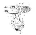
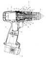
図1は、ドライバドリルの一例である震動ドライバドリルの斜視図、図2はその縦断面図で、震動ドライバドリル1は、左右一対の半割ハウジングからなる本体ハウジング2内にモータ3を収容し、そのモータ3の出力軸4から、本体ハウジング2内前方(図1,2の右側)に組み付けられるギヤアッセンブリ7を介して、ギヤアッセンブリ7から前方へ突出するスピンドル5へ回転伝達するもので、スピンドル5の前端には、先端でビットを把持可能なドリルチャック6が設けられている。8はモータ3を駆動させるスイッチ、9はハンドル、10はハンドル9の下端に装着された電源としてのバッテリーパックである。Hereinafter, embodiments of the present invention will be described with reference to the drawings.
FIG. 1 is a perspective view of a vibration driver drill as an example of a driver drill, FIG. 2 is a longitudinal sectional view thereof, and the
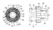
ギヤアッセンブリ7は、図3,4にも示すように、第一ギヤケース11と、その第一ギヤケース11の前方に組み付けられ、図5(A)に示す如く大径部13と小径部14との二段筒形状を有する第二ギヤケース12とを備え、第一ギヤケース11と大径部13との内部には、複数の遊星ギヤ15,15・・と、遊星ギヤ15,15・・を支持するキャリア16,16・・と、遊星ギヤ15,15・・の外周で噛合するインターナルギヤ17,17・・とを三段配置してなる周知の遊星歯車減速機構が収容されている。スピンドル5は、その後端が三段目のキャリア16と一体のロックカム18にスプライン結合されると共に、第二ギヤケース12の小径部14内でボールベアリング19,20によって軸支されている。よって、スピンドル5は、出力軸4の回転が減速されて伝達されると共に、軸方向へ前後移動可能ともなっている。 The
但し、スピンドル5は、その前方寄りに形成されたフランジ21と、ボールベアリング20との間で外装されたコイルバネ22とによって、常態では後述する第一カム26がボールベアリング20に当接する前進位置に付勢されている。23,24は、ボールベアリング20を挟む格好で小径部14の内周に前方から嵌入されてボールベアリング20を位置決めする筒状のスペーサ、25は、小径部14の前端にネジ止めされてスペーサ24を抜け止めする円盤状の止め板である。 However, the
また、スピンドル5におけるボールベアリング19,20間には、カム手段として、前方からリング状の第一カム26、第二カム27が夫々同軸で外装されている。第一カム26は、その後面に、周方向に連続する第一カム歯28,28・・を放射状に形成し、スペーサ23内でスピンドル5と一体に固着されている。第二カム27は、第一カム歯28と対向する前面に同じ形状の第二カム歯29,29・・を、後方外周面にスプライン部30を夫々形成してスピンドル5に遊挿され、回転及び軸方向での前後移動が可能であるが、前方へは、第1カム26と噛合する位置まで、後方へは、小径部14の内周に突設したストッパ31に規制され、複数のスチールボール32,32・・を保持する一対のワッシャー33,33に当接する位置まで夫々微動可能となっている。 Further, between the
さらに、小径部14には、前端から軸方向に沿ったガイド溝34,34が点対称に一対形成され、各ガイド溝34内に、コイルバネ35と震動切替レバー36とが夫々スライド可能に収容されている。各震動切替レバー36の後端内面側には、内側突起37が突設されて小径部14の内周側に突出し、前進位置で第二カム27のスプライン部30に係合可能となっている。また、各震動切替レバー36の前端外面側にも外側突起38が突設されて、小径部14の外周側に突出している。 Furthermore, a pair of
一方、小径部14には、本体ハウジング2の前端と略同径の操作リング40と、操作リング40より小径でその前方に位置するカムリング41と、カムリング41の外周から軸方向に延設され、周方向に等間隔で配置されて両リング40,41を連結する3つの連結板42,42・・とからなる操作部材としてのモードチェンジリング39が、本体ハウジング2の前端と止め板25との間で回転可能に外装されている。このモードチェンジリング39のカムリング41の後端縁に、震動切替レバー36の外側突起38が当接して、コイルバネ35によって前方へ付勢される震動切替レバー36の前進位置を規制可能となっている。また、カムリング41の後端縁には、点対称位置に台形状のカム凹部43,43が一対凹設されており、外側突起38の前方にカム凹部43が位置するモードチェンジリング39の回転位置では、震動切替レバー36が前進して、内側突起37を第二カム27のスプライン部30に係合させる。さらに、外側突起38の前方にカム凹部43が位置しないモードチェンジリング39の回転位置では、震動切替レバー36が後退し、内側突起37を第二カム27のスプライン部30から離脱させるようになっている。 On the other hand, the small-
44は、操作リング40の前方と止め板25との間でモードチェンジリング39へ回転可能に外装された第二操作部材としての筒状のチェンジリングで、内周には雌ネジ部45が形成されている。小径部14には、モードチェンジリング39の連結板42,42・・の間から雄ネジ部47を突出させたスプリングホルダ46が軸方向へ移動可能に外装されて、チェンジリング44の雌ネジ部45に螺合している。よって、モードチェンジリング39を回転操作すると、スプリングホルダ46は軸方向へネジ送りされることになる。
一方、小径部14の根元には、図5(B)にも示すように、外周縁に周方向へ等間隔で3つの外突起49,49・・を突設し、内周縁に左右対称で一対ずつ4つの内突起50,50・・を突設した中間部材としてのフラットワッシャ48が外装されて、図5(C)及び図6に示すように、外突起49,49・・がモードチェンジリング39の操作リング40の内周で軸方向に凹設された凹溝51,51・・に嵌合し、モードチェンジリング39と一体に回転可能且つ別体で軸方向へ移動可能となっている。小径部14の外周において、大径部13の前面から略フラットワッシャ48の厚み分だけ離れた位置より前方側には、図5(A)のように、フラットワッシャ48の内周形状と合致し、その合致位置以外では内突起50,50・・と軸方向で重なる干渉部としての突条52,52・・が軸方向に沿って突設されている。よって、フラットワッシャ48は、突条52のない小径部14の根元(後述する後退位置)で回転可能で、それより前方側への移動は、内突起50が突条52と軸方向で干渉しない図6の合致位置(固定解除位置)でのみ可能となる。 On the other hand, at the base of the small-
このフラットワッシャ48とスプリングホルダ46との間で小径部14に、押圧手段としてのコイルバネ53が外装されて、フラットワッシャ48を大径部13側へ押圧している。フラットワッシャ48の後方で大径部13内には、係合部材として、前後2個のスチールボール54,54・・が周方向へ等間隔に保持されて、遊星歯車減速機構の三段目で回転可能に設けられたインターナルギヤ17の前面に当接し、インターナルギヤ17の前面で周方向へ等間隔で突設された台形状のクラッチカム55,55・・と周方向で係合可能となっている。このスチールボール54,54及びフラットワッシャ48を介してコイルバネ53の付勢力が直接インターナルギヤ17へ伝わるため、インターナルギヤ17はコイルバネ53の付勢力によって回転規制され、チェンジリング44の回転操作に伴うスプリングホルダ46のネジ送りにより、コイルバネ53の軸方向長さを変化させることで、インターナルギヤ17への付勢力が変更可能となる。なお、この押圧状態で、フラットワッシャ48は大径部13の前面に非接触で近接した後退位置となる。 Between the
以上の如く構成された震動ドライバドリル1においては、以下に説明するように、モードチェンジリング39の回転位置と、それに伴う震動切替レバー36の前後移動及びフラットワッシャ48の回転とによって、3つの動作モードが選択可能となる。
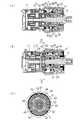
まず、フラットワッシャ48の内突起50が図4(C)のように軸方向で小径部14の突条52と干渉しない位置となるモードチェンジリング39の第一の回転位置では、カムリング41のカム凹部43は震動切替レバー36の前方から離れた位置にあるため、震動切替レバー36は図4のように後退位置にあって、内側突起37と第二カム27とは結合されない。よって、第二カム27は回転フリー状態、フラットワッシャ48は前方へ移動可能な状態で、チェンジリング44の回転操作によってフラットワッシャ48への押圧力が変更可能なクラッチモードとなる。In the
First, at the first rotation position of the
このクラッチモードでモータ3を駆動させてスピンドル5を回転させると、ドリルチャック6に装着したドライバビットでネジ締め等を行うことができる。ネジ締めが進んでスピンドル5への負荷が、インターナルギヤ17を固定するコイルバネ53の押圧力を超えると、インターナルギヤ17のクラッチカム55,55・・がスチールボール54,54及びフラットワッシャ48を前方へ押し出してインターナルギヤ17を空転させ、ネジ締めを終了させる(クラッチ作動)。なお、ドライバビットのネジへの押し付けによってスピンドル5が後退し、第一カム26が第二カム27と噛合することになるが、第二カム27は回転フリー状態となっているため、第一カム26と共に回転し、スピンドル5に震動は発生しない。 When the
次に、クラッチモードからモードチェンジリング39を30度左回転させた図7の第二の回転位置では、カムリング41のカム凹部43は未だ震動切替レバー36の前方になく、震動切替レバー36は後退位置のままであるが、フラットワッシャ48は同図(C)のように回転して内突起50を小径部14の突条52の後方に位置させる(固定位置)。よって、コイルバネ53の押圧力の大小にかかわらずフラットワッシャ48の前方への移動が突条52によって常に規制されるドリルモードとなる。
このドリルモードでスピンドル5を回転させると、スピンドル5への負荷にかかわらず、スチールボール54,54がインターナルギヤ17のクラッチカム55を乗り越えることがないため、インターナルギヤ17の固定状態は変わらず、スピンドル5の回転は継続する。なお、このときも第二カム27の回転フリー状態は変わらないため、スピンドル5に震動は発生しない。Next, in the second rotation position of FIG. 7 in which the
When the
そして、ドリルモードからモードチェンジリング39をさらに30度左回転させた図8の第三の回転位置では、カムリング41のカム凹部43は震動切替レバー36の前方に位置し、震動切替レバー36の前進を許容して内側突起37を第二カム27と結合させる。一方、フラットワッシャ48の内側突起37と小径部14の突条52との軸方向での干渉は変わらない。よって、スピンドル5の後退位置で第一カム26と第二カム27とが噛合する震動モードとなる。
この震動モードでスピンドル5を回転させた場合、ドリルビット等を被加工材に押し当ててスピンドル5が後退すると、スピンドル5と一体回転する第一カム26が、震動切替レバー36で固定される第二カム27と噛合するため、スピンドル5に震動が発生する。なお、突条52によるフラットワッシャ48の固定状態は変わらないため、スピンドル5への負荷にかかわらずスピンドル5の回転は継続することになる。Then, in the third rotation position of FIG. 8 in which the
When the
なお、本体ハウジング2の前端内周には、リーフスプリング56が固定される一方、モードチェンジリング39における操作リング40の後端外周には、図5(C)及び図6に示すように、各モードに対応する回転位置でリーフスプリング56が係合する凹部57,57・・が3箇所形成されて、モードチェンジリング39を各モードに位置決めするクリック作用が得られるようになっている。 A
このように上記形態の震動ドライバドリル1によれば、フラットワッシャ48の固定手段を、第二ギヤケース12の小径部14に設けられ、フラットワッシャ48の所定の回転位置でフラットワッシャ48と干渉してその移動を規制する突条52として、モードチェンジリング39の回転操作により、フラットワッシャ48を、突条52と干渉する固定位置と、突条52と干渉しない固定解除位置とに回転させることで、クラッチモードとドリルモードとの選択を可能としたことで、部品間の公差の影響なく、フラットワッシャ48を確実に固定することができる。よって、ドリルモードでのクラッチ誤動作が効果的に防止され、信頼性に優れたものとなる。 As described above, according to the
また、ここでは、モードチェンジリング39に、クラッチモード及びドリルモード以外の回転位置で、第二カム27を震動切替レバー36で固定させると共に、フラットワッシャ48が突条52と干渉する第三の回転位置を設定して、モードチェンジリング39の回転操作により、スピンドル55に震動モードをさらに選択可能としたことで、クラッチモード、ドリルモード、震動モードの3つの動作モードをモードチェンジリング39の回転操作のみで選択可能となり、使い勝手に優れる。
さらにここでは、クラッチモードのトルク調整用としてチェンジリング44をモードチェンジリング39と別に設けているから、動作モードの切替をチェンジリング44によるトルク調整位置に関係なく行うことができると共に、トルク調整の際に動作モードを誤って切り替えてしまうおそれもなくなる。Here, the
Further, here, since the
なお、上記形態では、第二ギヤケースの小径部に軸方向に突条を突設してフラットワッシャの移動規制を図っているが、干渉部としては、周方向に突設した突条やピン形状の突起等であってもフラットワッシャの移動規制は可能である。また、中間部材もフラットワッシャに限らず、筒状体であっても差し支えないし、係合部材もスチールボール以外に端部を円柱や円形としたピン等の採用も可能である。
さらに、上記形態では、震動モードを選択可能な震動ドライバドリルで説明しているが、カム手段を有さず震動モードがないドライバドリルであっても同様の固定手段は採用可能であるし、一つの操作部材のみで動作モードの選択とトルク調整とを可能としたドライバドリルや震動ドライバドリルであっても本発明は適用可能である。
In the above embodiment, the protrusion of the second gear case is protruded in the axial direction so as to restrict the movement of the flat washer. The movement of the flat washer can be restricted even if it is a protrusion or the like. Further, the intermediate member is not limited to a flat washer, and may be a cylindrical body, and the engaging member may be a pin or the like whose end is a cylinder or a circle in addition to a steel ball.
Further, in the above embodiment, the vibration driver drill capable of selecting the vibration mode is described. However, the same fixing means can be adopted even with a driver drill that does not have the cam means and does not have the vibration mode. The present invention can be applied even to a driver drill or a vibration driver drill that enables selection of an operation mode and torque adjustment with only one operation member.
1‥震動ドライバドリル、2‥本体ハウジング、3‥モータ、5‥スピンドル、7‥ギヤアッセンブリ、11‥第一ギヤケース、12‥第二ギヤケース、13‥大径部、14‥小径部、17‥インターナルギヤ、26‥第一カム、27‥第二カム、30‥スプライン部、36‥震動切替レバー、37‥内側突起、38‥外側突起、39‥モードチェンジリング、40‥操作リング、41‥カムリング、44‥チェンジリング、46‥スプリングホルダ、48‥フラットワッシャ、49‥外突起、50‥内突起、52‥突条、53‥コイルバネ。
DESCRIPTION OF
Claims (3)
Translated fromJapanese前記固定手段を、前記ギヤケースに設けられ、前記中間部材の所定の回転位置で前記中間部材と干渉してその移動を規制する干渉部として、前記操作部材の回転操作により、前記中間部材を、前記干渉部と干渉する固定位置と、前記干渉部と干渉しない固定解除位置とに回転させることで、前記クラッチモードとドリルモードとの選択を可能としたことを特徴とするドライバドリル。In the housing, a motor and a planetary gear reduction mechanism housed in a gear case are provided, and the output of the motor can be transmitted to the spindle protruding forward of the housing via the planetary gear reduction mechanism, In the planetary gear speed reduction mechanism, the internal gear of the front stage of the spindle is rotatably provided, and the gear case holds an engagement member that can be engaged with an end surface of the internal gear, and in front of the engagement member, A pressing means for pressing and fixing the engaging member via an intermediate member held by the gear case; a fixing means capable of restricting the forward movement of the intermediate member; and An operation member capable of switching the restriction state, and the movement of the intermediate member is released by rotating the operation member to A clutch mode to permit rotation, a said intermediate member driver drill which enables selecting a drill mode in which the mobile restricts the blocking idling of the internal gear of
The fixing member is provided in the gear case as an interference unit that interferes with the intermediate member at a predetermined rotational position of the intermediate member and restricts the movement thereof, by rotating the operation member, the intermediate member is A driver drill characterized in that the clutch mode and the drill mode can be selected by rotating to a fixed position that interferes with the interference part and a fixed release position that does not interfere with the interference part.
The driver drill according to claim 1 or 2, further comprising a second operation member capable of adjusting a pressing force of the pressing means by a rotating operation.
Priority Applications (5)
| Application Number | Priority Date | Filing Date | Title |
|---|---|---|---|
| JP2004004610AJP4227028B2 (en) | 2004-01-09 | 2004-01-09 | Screwdriver drill |
| CNB2004100824690ACN100500351C (en) | 2004-01-09 | 2004-09-22 | multifunctional electric drill |
| US10/984,039US7201235B2 (en) | 2004-01-09 | 2004-11-09 | Driver drill |
| EP04027017AEP1555091B1 (en) | 2004-01-09 | 2004-11-12 | Driver drill |
| DE602004016815TDE602004016815D1 (en) | 2004-01-09 | 2004-11-12 | Drill / power driven screwdriver |
Applications Claiming Priority (1)
| Application Number | Priority Date | Filing Date | Title |
|---|---|---|---|
| JP2004004610AJP4227028B2 (en) | 2004-01-09 | 2004-01-09 | Screwdriver drill |
Publications (2)
| Publication Number | Publication Date |
|---|---|
| JP2005193361A JP2005193361A (en) | 2005-07-21 |
| JP4227028B2true JP4227028B2 (en) | 2009-02-18 |
Family
ID=34616825
Family Applications (1)
| Application Number | Title | Priority Date | Filing Date |
|---|---|---|---|
| JP2004004610AExpired - Fee RelatedJP4227028B2 (en) | 2004-01-09 | 2004-01-09 | Screwdriver drill |
Country Status (5)
| Country | Link |
|---|---|
| US (1) | US7201235B2 (en) |
| EP (1) | EP1555091B1 (en) |
| JP (1) | JP4227028B2 (en) |
| CN (1) | CN100500351C (en) |
| DE (1) | DE602004016815D1 (en) |
Cited By (1)
| Publication number | Priority date | Publication date | Assignee | Title |
|---|---|---|---|---|
| EP2554306A2 (en) | 2011-08-05 | 2013-02-06 | Makita Corporation | Electric power tool |
Families Citing this family (74)
| Publication number | Priority date | Publication date | Assignee | Title |
|---|---|---|---|---|
| DE102004020177B4 (en)* | 2004-04-24 | 2024-07-18 | Robert Bosch Gmbh | Hand tool with a rotating and/or percussive drive |
| DE102004030760A1 (en)* | 2004-06-25 | 2006-01-19 | Robert Bosch Gmbh | Device with a torque limiting unit |
| US20060144185A1 (en)* | 2005-01-03 | 2006-07-06 | Feng-Chun Tsai | Shift-positioning structure of gear case |
| GB0503784D0 (en)* | 2005-02-24 | 2005-03-30 | Black & Decker Inc | Hammer drill |
| US20060213675A1 (en)* | 2005-03-24 | 2006-09-28 | Whitmire Jason P | Combination drill |
| US7410007B2 (en)* | 2005-09-13 | 2008-08-12 | Eastway Fair Company Limited | Impact rotary tool with drill mode |
| US7980324B2 (en) | 2006-02-03 | 2011-07-19 | Black & Decker Inc. | Housing and gearbox for drill or driver |
| DE502006001594D1 (en)* | 2006-03-18 | 2008-10-30 | Metabowerke Gmbh | Electric hand tool |
| TW200740566A (en)* | 2006-04-25 | 2007-11-01 | Mobiletron Electronics Co Ltd | Electric tool |
| ATE400410T1 (en)* | 2006-05-19 | 2008-07-15 | Black & Decker Inc | MODE SWITCHING DEVICE FOR A POWER-OPERATED TOOL |
| USD592926S1 (en)* | 2006-05-22 | 2009-05-26 | Robert Bosch Gmbh | Power drill and battery pack |
| USD592476S1 (en)* | 2006-05-25 | 2009-05-19 | Robert Bosch Gmbh | Power drill with battery pack |
| USD577272S1 (en)* | 2006-09-06 | 2008-09-23 | Black & Decker Inc. | Cordless drill |
| US7578357B2 (en)* | 2006-09-12 | 2009-08-25 | Black & Decker Inc. | Driver with external torque value indicator integrated with spindle lock and related method |
| US7806198B2 (en) | 2007-06-15 | 2010-10-05 | Black & Decker Inc. | Hybrid impact tool |
| US7762349B2 (en) | 2007-11-21 | 2010-07-27 | Black & Decker Inc. | Multi-speed drill and transmission with low gear only clutch |
| US7735575B2 (en) | 2007-11-21 | 2010-06-15 | Black & Decker Inc. | Hammer drill with hard hammer support structure |
| US7717192B2 (en) | 2007-11-21 | 2010-05-18 | Black & Decker Inc. | Multi-mode drill with mode collar |
| US7770660B2 (en) | 2007-11-21 | 2010-08-10 | Black & Decker Inc. | Mid-handle drill construction and assembly process |
| US7798245B2 (en) | 2007-11-21 | 2010-09-21 | Black & Decker Inc. | Multi-mode drill with an electronic switching arrangement |
| US7854274B2 (en) | 2007-11-21 | 2010-12-21 | Black & Decker Inc. | Multi-mode drill and transmission sub-assembly including a gear case cover supporting biasing |
| US7717191B2 (en) | 2007-11-21 | 2010-05-18 | Black & Decker Inc. | Multi-mode hammer drill with shift lock |
| CN201220406Y (en)* | 2008-02-03 | 2009-04-15 | 南京德朔实业有限公司 | Electric tool |
| CN102015169B (en)* | 2008-04-22 | 2013-12-11 | 杰勒德·格兰特 | Impact mechanism |
| EP2318636B1 (en)* | 2008-08-06 | 2019-01-09 | Milwaukee Electric Tool Corporation | Precision torque tool |
| US9193053B2 (en) | 2008-09-25 | 2015-11-24 | Black & Decker Inc. | Hybrid impact tool |
| US8251158B2 (en) | 2008-11-08 | 2012-08-28 | Black & Decker Inc. | Multi-speed power tool transmission with alternative ring gear configuration |
| EP2216114B1 (en)* | 2009-02-05 | 2013-08-28 | Techtronic Power Tools Technology Limited | Power tool chuck assembly with hammer mechanism |
| US8631880B2 (en)* | 2009-04-30 | 2014-01-21 | Black & Decker Inc. | Power tool with impact mechanism |
| USD628039S1 (en)* | 2009-12-16 | 2010-11-30 | Hitachi Koki Co., Ltd. | Portable electric driver |
| USD625164S1 (en)* | 2009-12-18 | 2010-10-12 | Robert Bosch Gmbh | Cordless drill driver |
| DE102009054930B4 (en)* | 2009-12-18 | 2017-07-27 | Robert Bosch Gmbh | drilling machine |
| US8460153B2 (en)* | 2009-12-23 | 2013-06-11 | Black & Decker Inc. | Hybrid impact tool with two-speed transmission |
| US8584770B2 (en)* | 2010-03-23 | 2013-11-19 | Black & Decker Inc. | Spindle bearing arrangement for a power tool |
| CN102335904B (en)* | 2010-07-20 | 2014-04-16 | 苏州宝时得电动工具有限公司 | Power tool |
| TWM394214U (en)* | 2010-08-10 | 2010-12-11 | Top Gearbox Industry Co Ltd | Device for unidirectional output of vibration and rotation power |
| DE102010042682A1 (en)* | 2010-10-20 | 2012-04-26 | Robert Bosch Gmbh | drilling machine |
| US8714888B2 (en) | 2010-10-25 | 2014-05-06 | Black & Decker Inc. | Power tool transmission |
| WO2012061176A2 (en) | 2010-11-04 | 2012-05-10 | Milwaukee Electric Tool Corporation | Impact tool with adjustable clutch |
| DE102010063953A1 (en)* | 2010-12-22 | 2012-06-28 | Robert Bosch Gmbh | Hand tool |
| JP5628079B2 (en) | 2011-04-05 | 2014-11-19 | 株式会社マキタ | Vibration driver drill |
| SE535899C2 (en)* | 2011-05-04 | 2013-02-12 | Atlas Copco Ind Tech Ab | Nut wrench with torque unit |
| US9481080B2 (en) | 2011-07-29 | 2016-11-01 | Black & Decker Inc. | Multispeed power tool |
| US11059160B2 (en) | 2011-07-29 | 2021-07-13 | Black & Decker Inc. | Multispeed power tool |
| DE102011081661B4 (en)* | 2011-08-26 | 2023-11-30 | Robert Bosch Gmbh | Switchable gearbox for a hand-held machine tool |
| CN102431013B (en)* | 2011-09-13 | 2014-08-20 | 南京久驰机电实业有限公司 | Electric drill with driving mode switching |
| EP2809470B1 (en) | 2012-02-03 | 2020-01-15 | Milwaukee Electric Tool Corporation | Rotary hammer |
| TWI491477B (en)* | 2012-09-21 | 2015-07-11 | Nitto Kohki Co | Electric screwdriver |
| WO2014062868A1 (en)* | 2012-10-19 | 2014-04-24 | Milwaukee Electric Tool Corporation | Hammer drill |
| US9494200B2 (en)* | 2013-03-14 | 2016-11-15 | Black & Decker Inc. | Clutch for power tool |
| DE102013208895B4 (en)* | 2013-05-14 | 2023-12-14 | Robert Bosch Gmbh | Hand tool device |
| US9914176B2 (en)* | 2013-09-30 | 2018-03-13 | Chervon (Hk) Limited | Rotary tool |
| DE102013222550B4 (en)* | 2013-11-06 | 2024-12-19 | Robert Bosch Gmbh | hand tool machine |
| CN104874834B (en)* | 2014-02-28 | 2018-06-15 | 苏州宝时得电动工具有限公司 | Impact drill |
| CN104308222B (en)* | 2014-07-14 | 2017-03-01 | 岳云峰 | Electric drill with adjustable drill bit diameter and using method thereof |
| JP6543480B2 (en)* | 2015-02-20 | 2019-07-10 | 株式会社マキタ | Power tool with vibration mechanism |
| CN104889942B (en)* | 2015-05-04 | 2017-01-11 | 浙江亚特电器有限公司 | Function switchover device and multifunctional electric drill |
| WO2016196918A1 (en)* | 2015-06-05 | 2016-12-08 | Ingersoll-Rand Company | Power tool user interfaces |
| WO2016196984A1 (en) | 2015-06-05 | 2016-12-08 | Ingersoll-Rand Company | Power tools with user-selectable operational modes |
| US11260517B2 (en) | 2015-06-05 | 2022-03-01 | Ingersoll-Rand Industrial U.S., Inc. | Power tool housings |
| WO2016196979A1 (en) | 2015-06-05 | 2016-12-08 | Ingersoll-Rand Company | Impact tools with ring gear alignment features |
| CN106641171B (en)* | 2015-10-30 | 2021-06-11 | 苏州宝时得电动工具有限公司 | Speed changing tool |
| JP6675188B2 (en) | 2015-12-03 | 2020-04-01 | 株式会社マキタ | Power tool with vibration mechanism |
| CN106239433A (en)* | 2016-09-14 | 2016-12-21 | 群胜科技(苏州)有限公司 | A kind of electric impact drill gear adjusting device |
| CN107999825B (en)* | 2016-11-01 | 2024-06-14 | 苏州宝时得电动工具有限公司 | Power tool and method for mounting working member |
| CN108068066B (en)* | 2016-11-16 | 2023-09-12 | 苏州宝时得电动工具有限公司 | Conversion chuck, tool main body matched with conversion chuck for use and matched use method |
| CN107433483B (en)* | 2017-04-11 | 2019-03-19 | 上海舟润实业有限公司 | A kind of plate cutting device |
| CN210188575U (en)* | 2018-06-06 | 2020-03-27 | 苏州宝时得电动工具有限公司 | Hand-held power tool |
| JP7049929B2 (en)* | 2018-06-06 | 2022-04-07 | 株式会社マキタ | Power tools and electric vibration driver drills |
| CN109396487A (en)* | 2018-11-08 | 2019-03-01 | 江苏圣金特汽车配件有限公司 | Perforating device is used in a kind of processing of automobile parts |
| JP7253397B2 (en)* | 2019-01-28 | 2023-04-06 | 株式会社マキタ | Electric tool |
| DE102019113212A1 (en)* | 2019-05-10 | 2020-11-12 | Festool Gmbh | Attachment and hand machine tool with attachment |
| JP7458167B2 (en)* | 2019-11-08 | 2024-03-29 | 株式会社マキタ | electric screwdriver drill |
| CN114542352A (en)* | 2022-03-01 | 2022-05-27 | 东风柳州汽车有限公司 | Shaft body linkage structure and water pump structure |
Family Cites Families (16)
| Publication number | Priority date | Publication date | Assignee | Title |
|---|---|---|---|---|
| US37905A (en)* | 1863-03-17 | Improvement in sheep-racks | ||
| DE3321635A1 (en) | 1983-06-15 | 1984-12-20 | Hitachi Koki Co., Ltd., Tokio/Tokyo | Torque setting mechanism for motor-driven screwdrivers |
| DE9016415U1 (en) | 1990-12-03 | 1991-07-25 | Licentia Patent-Verwaltungs-Gmbh, 6000 Frankfurt | Hand-held power tool with a device for adjusting the torque |
| JP2558753Y2 (en)* | 1991-10-31 | 1998-01-14 | 株式会社マキタ | Power transmission mechanism for rotary electric tools |
| GB9304540D0 (en) | 1993-03-05 | 1993-04-21 | Black & Decker Inc | Power tool and mechanism |
| US5531278A (en)* | 1995-07-07 | 1996-07-02 | Lin; Pi-Chu | Power drill with drill bit unit capable of providing intermittent axial impact |
| JPH0979292A (en) | 1995-09-08 | 1997-03-25 | Hitachi Koki Co Ltd | Clutch mechanism |
| JP3291609B2 (en)* | 1996-02-13 | 2002-06-10 | 株式会社マキタ | Power tool clutch mechanism |
| US6142242A (en)* | 1999-02-15 | 2000-11-07 | Makita Corporation | Percussion driver drill, and a changeover mechanism for changing over a plurality of operating modes of an apparatus |
| JP3677190B2 (en) | 2000-03-03 | 2005-07-27 | 株式会社マキタ | Clutch mechanism of driver drill |
| US6338404B1 (en)* | 2000-05-22 | 2002-01-15 | Power Network Industry Co., Ltd. | Locking device of power hand tool |
| US6202759B1 (en)* | 2000-06-24 | 2001-03-20 | Power Network Industry Co., Ltd. | Switch device for a power tool |
| US6533093B2 (en) | 2001-04-19 | 2003-03-18 | Power Network Industry Co., Ltd. | Torque adjusting device for a drill |
| JP3881232B2 (en) | 2001-12-21 | 2007-02-14 | 株式会社マキタ | Screwdriver drill |
| JP4155751B2 (en)* | 2002-03-20 | 2008-09-24 | 日立工機株式会社 | Electric tool |
| US6892827B2 (en)* | 2002-08-27 | 2005-05-17 | Matsushita Electric Works, Ltd. | Electrically operated vibrating drill/driver |
- 2004
- 2004-01-09JPJP2004004610Apatent/JP4227028B2/ennot_activeExpired - Fee Related
- 2004-09-22CNCNB2004100824690Apatent/CN100500351C/ennot_activeExpired - Lifetime
- 2004-11-09USUS10/984,039patent/US7201235B2/ennot_activeExpired - Lifetime
- 2004-11-12DEDE602004016815Tpatent/DE602004016815D1/ennot_activeExpired - Lifetime
- 2004-11-12EPEP04027017Apatent/EP1555091B1/ennot_activeExpired - Lifetime
Cited By (2)
| Publication number | Priority date | Publication date | Assignee | Title |
|---|---|---|---|---|
| EP2554306A2 (en) | 2011-08-05 | 2013-02-06 | Makita Corporation | Electric power tool |
| US8760102B2 (en) | 2011-08-05 | 2014-06-24 | Makita Corporation | Electric power tool |
Also Published As
| Publication number | Publication date |
|---|---|
| US20050150669A1 (en) | 2005-07-14 |
| CN100500351C (en) | 2009-06-17 |
| JP2005193361A (en) | 2005-07-21 |
| EP1555091A2 (en) | 2005-07-20 |
| DE602004016815D1 (en) | 2008-11-13 |
| EP1555091B1 (en) | 2008-10-01 |
| EP1555091A3 (en) | 2007-01-31 |
| US7201235B2 (en) | 2007-04-10 |
| CN1636658A (en) | 2005-07-13 |
Similar Documents
| Publication | Publication Date | Title |
|---|---|---|
| JP4227028B2 (en) | Screwdriver drill | |
| US6142242A (en) | Percussion driver drill, and a changeover mechanism for changing over a plurality of operating modes of an apparatus | |
| JP4468786B2 (en) | Impact tools | |
| US7124839B2 (en) | Impact driver having an external mechanism which operation mode can be selectively switched between impact and drill modes | |
| EP2508303B1 (en) | Percussion driver drill | |
| US8684882B2 (en) | Power tool | |
| JP5340881B2 (en) | Impact tool | |
| JPH0539814U (en) | Power transmission mechanism for rotary power tools | |
| JP2016153153A (en) | Electric tool with vibration mechanism | |
| US20120255755A1 (en) | Power tool | |
| JP4391921B2 (en) | Vibration drill | |
| JP4824812B2 (en) | Impact tools | |
| JP3655481B2 (en) | Vibration driver drill | |
| JP2001088052A (en) | Rotary tool with impact mechanism | |
| JP5341429B2 (en) | Electric tool | |
| US20220152792A1 (en) | Screw-tightening tool | |
| JP2012006101A (en) | Impact tool | |
| JP2000233305A (en) | Vibration driver drill | |
| JP2005118961A (en) | Driver drill | |
| JP4767593B2 (en) | Ignition switch operating device for vehicle | |
| JP3996383B2 (en) | Electric tool | |
| JP3881232B2 (en) | Screwdriver drill | |
| JP4366688B2 (en) | Electric tool | |
| JP4448049B2 (en) | Electric screwdriver |
Legal Events
| Date | Code | Title | Description |
|---|---|---|---|
| A621 | Written request for application examination | Free format text:JAPANESE INTERMEDIATE CODE: A621 Effective date:20060724 | |
| A977 | Report on retrieval | Free format text:JAPANESE INTERMEDIATE CODE: A971007 Effective date:20081023 | |
| TRDD | Decision of grant or rejection written | ||
| A01 | Written decision to grant a patent or to grant a registration (utility model) | Free format text:JAPANESE INTERMEDIATE CODE: A01 Effective date:20081028 | |
| A01 | Written decision to grant a patent or to grant a registration (utility model) | Free format text:JAPANESE INTERMEDIATE CODE: A01 | |
| A61 | First payment of annual fees (during grant procedure) | Free format text:JAPANESE INTERMEDIATE CODE: A61 Effective date:20081127 | |
| FPAY | Renewal fee payment (event date is renewal date of database) | Free format text:PAYMENT UNTIL: 20111205 Year of fee payment:3 | |
| R150 | Certificate of patent or registration of utility model | Ref document number:4227028 Country of ref document:JP Free format text:JAPANESE INTERMEDIATE CODE: R150 | |
| FPAY | Renewal fee payment (event date is renewal date of database) | Free format text:PAYMENT UNTIL: 20111205 Year of fee payment:3 | |
| FPAY | Renewal fee payment (event date is renewal date of database) | Free format text:PAYMENT UNTIL: 20111205 Year of fee payment:3 | |
| FPAY | Renewal fee payment (event date is renewal date of database) | Free format text:PAYMENT UNTIL: 20121205 Year of fee payment:4 | |
| R250 | Receipt of annual fees | Free format text:JAPANESE INTERMEDIATE CODE: R250 | |
| FPAY | Renewal fee payment (event date is renewal date of database) | Free format text:PAYMENT UNTIL: 20121205 Year of fee payment:4 | |
| FPAY | Renewal fee payment (event date is renewal date of database) | Free format text:PAYMENT UNTIL: 20131205 Year of fee payment:5 | |
| R250 | Receipt of annual fees | Free format text:JAPANESE INTERMEDIATE CODE: R250 | |
| R250 | Receipt of annual fees | Free format text:JAPANESE INTERMEDIATE CODE: R250 | |
| R250 | Receipt of annual fees | Free format text:JAPANESE INTERMEDIATE CODE: R250 | |
| R250 | Receipt of annual fees | Free format text:JAPANESE INTERMEDIATE CODE: R250 | |
| R250 | Receipt of annual fees | Free format text:JAPANESE INTERMEDIATE CODE: R250 | |
| R250 | Receipt of annual fees | Free format text:JAPANESE INTERMEDIATE CODE: R250 | |
| R250 | Receipt of annual fees | Free format text:JAPANESE INTERMEDIATE CODE: R250 | |
| R250 | Receipt of annual fees | Free format text:JAPANESE INTERMEDIATE CODE: R250 | |
| R250 | Receipt of annual fees | Free format text:JAPANESE INTERMEDIATE CODE: R250 | |
| R250 | Receipt of annual fees | Free format text:JAPANESE INTERMEDIATE CODE: R250 | |
| R250 | Receipt of annual fees | Free format text:JAPANESE INTERMEDIATE CODE: R250 | |
| LAPS | Cancellation because of no payment of annual fees |