JP4226730B2 - Object region information generation method, object region information generation device, video information processing method, and information processing device - Google Patents
Object region information generation method, object region information generation device, video information processing method, and information processing deviceDownload PDFInfo
- Publication number
- JP4226730B2 JP4226730B2JP18703399AJP18703399AJP4226730B2JP 4226730 B2JP4226730 B2JP 4226730B2JP 18703399 AJP18703399 AJP 18703399AJP 18703399 AJP18703399 AJP 18703399AJP 4226730 B2JP4226730 B2JP 4226730B2
- Authority
- JP
- Japan
- Prior art keywords
- approximate
- information
- coordinate
- frame
- video
- Prior art date
- Legal status (The legal status is an assumption and is not a legal conclusion. Google has not performed a legal analysis and makes no representation as to the accuracy of the status listed.)
- Expired - Fee Related
Links
Images


Classifications
- H—ELECTRICITY
- H04—ELECTRIC COMMUNICATION TECHNIQUE
- H04N—PICTORIAL COMMUNICATION, e.g. TELEVISION
- H04N19/00—Methods or arrangements for coding, decoding, compressing or decompressing digital video signals
- H04N19/70—Methods or arrangements for coding, decoding, compressing or decompressing digital video signals characterised by syntax aspects related to video coding, e.g. related to compression standards
- G—PHYSICS
- G06—COMPUTING OR CALCULATING; COUNTING
- G06T—IMAGE DATA PROCESSING OR GENERATION, IN GENERAL
- G06T7/00—Image analysis
- G06T7/20—Analysis of motion
- G06T7/246—Analysis of motion using feature-based methods, e.g. the tracking of corners or segments
- G06T7/251—Analysis of motion using feature-based methods, e.g. the tracking of corners or segments involving models
- G—PHYSICS
- G06—COMPUTING OR CALCULATING; COUNTING
- G06V—IMAGE OR VIDEO RECOGNITION OR UNDERSTANDING
- G06V10/00—Arrangements for image or video recognition or understanding
- G06V10/40—Extraction of image or video features
- G06V10/46—Descriptors for shape, contour or point-related descriptors, e.g. scale invariant feature transform [SIFT] or bags of words [BoW]; Salient regional features
- G—PHYSICS
- G06—COMPUTING OR CALCULATING; COUNTING
- G06V—IMAGE OR VIDEO RECOGNITION OR UNDERSTANDING
- G06V10/00—Arrangements for image or video recognition or understanding
- G06V10/70—Arrangements for image or video recognition or understanding using pattern recognition or machine learning
- G06V10/74—Image or video pattern matching; Proximity measures in feature spaces
- G06V10/75—Organisation of the matching processes, e.g. simultaneous or sequential comparisons of image or video features; Coarse-fine approaches, e.g. multi-scale approaches; using context analysis; Selection of dictionaries
- G06V10/752—Contour matching
- H—ELECTRICITY
- H04—ELECTRIC COMMUNICATION TECHNIQUE
- H04N—PICTORIAL COMMUNICATION, e.g. TELEVISION
- H04N19/00—Methods or arrangements for coding, decoding, compressing or decompressing digital video signals
- H04N19/20—Methods or arrangements for coding, decoding, compressing or decompressing digital video signals using video object coding
- H—ELECTRICITY
- H04—ELECTRIC COMMUNICATION TECHNIQUE
- H04N—PICTORIAL COMMUNICATION, e.g. TELEVISION
- H04N19/00—Methods or arrangements for coding, decoding, compressing or decompressing digital video signals
- H04N19/50—Methods or arrangements for coding, decoding, compressing or decompressing digital video signals using predictive coding
- H04N19/503—Methods or arrangements for coding, decoding, compressing or decompressing digital video signals using predictive coding involving temporal prediction
- H04N19/51—Motion estimation or motion compensation
- H04N19/537—Motion estimation other than block-based
- H04N19/54—Motion estimation other than block-based using feature points or meshes
- H—ELECTRICITY
- H04—ELECTRIC COMMUNICATION TECHNIQUE
- H04N—PICTORIAL COMMUNICATION, e.g. TELEVISION
- H04N19/00—Methods or arrangements for coding, decoding, compressing or decompressing digital video signals
- H04N19/50—Methods or arrangements for coding, decoding, compressing or decompressing digital video signals using predictive coding
- H04N19/503—Methods or arrangements for coding, decoding, compressing or decompressing digital video signals using predictive coding involving temporal prediction
- H04N19/51—Motion estimation or motion compensation
- H04N19/537—Motion estimation other than block-based
- H04N19/543—Motion estimation other than block-based using regions
- G—PHYSICS
- G06—COMPUTING OR CALCULATING; COUNTING
- G06T—IMAGE DATA PROCESSING OR GENERATION, IN GENERAL
- G06T2207/00—Indexing scheme for image analysis or image enhancement
- G06T2207/10—Image acquisition modality
- G06T2207/10016—Video; Image sequence
- G—PHYSICS
- G06—COMPUTING OR CALCULATING; COUNTING
- G06V—IMAGE OR VIDEO RECOGNITION OR UNDERSTANDING
- G06V10/00—Arrangements for image or video recognition or understanding
- G06V10/40—Extraction of image or video features
- G06V10/46—Descriptors for shape, contour or point-related descriptors, e.g. scale invariant feature transform [SIFT] or bags of words [BoW]; Salient regional features
- G06V10/469—Contour-based spatial representations, e.g. vector-coding
- G06V10/471—Contour-based spatial representations, e.g. vector-coding using approximation functions
Landscapes
- Engineering & Computer Science (AREA)
- Multimedia (AREA)
- Computer Vision & Pattern Recognition (AREA)
- Theoretical Computer Science (AREA)
- Signal Processing (AREA)
- Physics & Mathematics (AREA)
- General Physics & Mathematics (AREA)
- Databases & Information Systems (AREA)
- Artificial Intelligence (AREA)
- Computing Systems (AREA)
- Health & Medical Sciences (AREA)
- Evolutionary Computation (AREA)
- General Health & Medical Sciences (AREA)
- Medical Informatics (AREA)
- Software Systems (AREA)
- Image Analysis (AREA)
- Processing Or Creating Images (AREA)
- Information Retrieval, Db Structures And Fs Structures Therefor (AREA)
- Studio Circuits (AREA)
- Compression Or Coding Systems Of Tv Signals (AREA)
Description
Translated fromJapanese【0001】
【発明の属する技術分野】
本発明は、映像中の物体の領域に関する情報を生成するための物体領域情報生成方法、映像中の物体の領域に関する情報を生成するための物体領域情報生成装置、並びに映像中の物体に対する指定を受け所定の処理を行う情報処理装置及びそのための映像情報処理方法に関する。
【0002】
【従来の技術】
ハイパーメディアは、映像、音声、テキストなどのメディアの間にハイパーリンクと呼ばれる関連情報を付与し、相互に参照できるようにしたものである。映像を中心にした場合、例えば映像中の登場物体に関連情報が付与されており、この物体が指示されると関連情報の表示を行うというものがハイパーメディアの代表例である。このとき、映像中の物体は映像のフレーム番号もしくはタイムスタンプと映像中の領域を特定する情報とで表現され、映像データの中にもしくは別データとして記録されている。
【0003】
映像中の領域を特定する方法としては、マスク画像がよく利用されてきた。これは指定領域内の場合と指定領域外の場合で異なる画素値を与えて構成する画像である。例えば、領域内の場合は1、領域外の場合は0という画素値を与えるのが最も簡単な方法である。また、CGなどに使われるα値を利用することもある。通常、α値は256階調の値を表現できるので、そのうちの一部を使い、例えば指定領域内の場合は255、指定領域外の場合は0と表現する。このようなマスク画像により画像中の領域が表現されている場合、あるフレームにおける画素が、指定領域内であるかどうかを判定するには、そのフレームに該当するマスク画像の該当画素の値を読み取り、0であるか255であるかにより簡単に判定することができる。マスク画像はどのような形の領域でも、また不連続な領域でも表現できるという自由度を持っているが、画像サイズと同じサイズの画素を持つ必要がある。
【0004】
マスク画像のデータ量を削減するために、マスク画像の圧縮がよく利用される。0、1の2値のマスク画像の場合には、2値画像としての処理ができるため、ファクシミリ等で用いられている圧縮方法が利用されることが多い。また、ISO/IEC動画圧縮標準化グループMPEG(Moving Picture Experts Group)が標準化しているMPEG−4では、0,1の2値のマスク画像の他、α値を利用したマスク画像までを圧縮対象とした任意形状符号化を採用することになっている。これは、動き補償を用いた圧縮手法であり、圧縮効率が向上するが、その分、圧縮・復号過程は複雑になる。
【0005】
以上のように映像中のある領域を表現するにはマスク画像かあるいはマスク画像を圧縮したものを利用することが多かったが、領域を特定するためのデータとしては、より簡単にかつ高速に取り出すことが可能でデータ量も小さく、そして容易に扱うことができる形態のものが望まれている。
【0006】
一方、映像中の動く物体の関連情報を表示させるような操作が通常想定されるハイパーメディアにおいては、静止画像を対象とするのとは異なって物体の指示にある程度の困難さを伴うものであり、ユーザが物体の特定の箇所を狙ってそこを指示することは通常難しく、またユーザも通常は物体の例えば中心付近を漠然と狙って指示しようとする場合が多いと考えられ、さらに物体の動きによっては厳密には物体の外部であるような物体の近傍を指示してしまうことも多い。したがって、領域を特定するためのデータとして、このようなメディアにより適合した形態のものが望まれている。また、映像中の動く物体の関連情報を表示するようなシステムにおいては、ユーザによる映像中の動く物体の指示をより容易にするように支援する機構が望まれている。
【0007】
【発明が解決しようとする課題】
以上説明したように、映像中の所望の物体の領域を表現する方法として、マスク画像ではデータ量が多くなるという問題があり、また、マスク画像を圧縮して用いると符号化・復号化が複雑になり、しかも直接データを編集することができないためハンドリングが難しいという問題があった。
【0008】
また、ユーザによる映像中の動く物体の指示をより容易にするような仕組みが提供されていないという問題があった。
【0009】
本発明は、上記事情を考慮してなされたもので、映像中の所望の物体の領域を少ないデータ量で記述でき且つその作成やそのデータの扱いも容易にする物体領域情報生成方法及び物体領域情報生成装置を提供することを目的とする。
【0010】
また、本発明は、ユーザによる映像中の物体の指示やその判定を容易にする物体領域情報生成方法及び物体領域情報生成装置並びに映像情報処理方法及び情報処理装置を提供することを目的とする。
【0012】
【課題を解決するための手段】
本発明は、第1処理手段と第2処理手段と第3処理手段と生成手段とを備え、映像中における任意の物体の領域に関する情報を連続する複数フレームに渡って記述した物体領域情報を生成するための物体領域情報生成装置の、物体領域情報生成方法であって、前記第1処理手段が、対象となる前記複数フレームについて、映像中における対象となる物体の領域を、1又は複数の近似図形を用いて近似するステップと、前記第2処理手段が、前記近似に用いられた各近似図形について、当該近似図形の図形種に応じて、当該近似図形を特定可能な所定数の代表点それぞれの前記複数フレーム中におけるX座標の座標値及びY座標の座標値を求めるステップと、前記第3処理手段が、前記近似に用いられた各近似図形について、当該近似図形の各代表点の各座標ごとに、連続する前記複数フレームに渡って求められた当該座標の座標値の時系列の軌跡を、2次以上の多項式のスプライン関数で近似し、該スプライン関数のパラメータを求めるステップと、前記生成手段が、前記物体領域情報として、少なくとも、対象となる前記複数フレームのうちの先頭のフレームの番号及び最終のフレームの番号もしくは先頭のフレームのタイムスタンプ及び最終のフレームのタイムスタンプを特定可能な情報と、前記近似に用いられた近似図形の数と、前記近似に用いられた各近似図形の図形種を識別する情報と、前記近似に用いられた各近似図形の各代表点の各座標ごとに求められた前記スプライン関数のパラメータとを含む物体領域情報を生成するステップとを有し、前記スプライン関数のパラメータは、それぞれ、当該近似図形の当該代表点の当該座標について、前記スプライン関数の各々の節点の座標値を示す情報及び該節点の座標値とともに用いて前記軌跡を特定可能な情報を含むことを特徴とする。
【0016】
対象となる前記複数フレームのうちの先頭のフレームの番号及び最終のフレームの番号もしくは先頭のフレームのタイムスタンプ及び最終のフレームのタイムスタンプを特定可能な情報は、例えば、先頭のフレームの番号及び最終のフレームの番号、あるいは先頭のフレームの番号及び先頭のフレームの番号と最終のフレームの番号との差分である。タイムスタンプを用いる場合も同様である。
【0017】
好ましくは、前記関数のパラメータは、前記軌跡の節点の位置データおよび該節点の位置データとともに用いて前記軌跡を特定可能な情報であるようにしてもよい。あるいは、前記関数のパラメータは、関数の係数であるようにしてもよい。
【0018】
好ましくは、前記物体の領域に対する近似図形の代表点もしくは前記物体の領域の特徴点が複数存在する場合に、現在のフレームにおける複数の代表点もしくは特徴点の各々が互いに隣接するフレームにおける複数の代表点もしくは特徴点のいずれに対応するかを特定するようにしてもよい。
【0019】
好ましくは、前記物体に関連付けられている関連情報または該関連情報へのアクセス方法を示す情報を併せて記述するようにしてもよい。
【0021】
また、本発明は、映像を表示している画面において特定の物体が指定されたか否かを判定するための映像情報処理方法であって、映像を表示している画面において任意の位置が指定された際、該映像中に予め設定された物体の領域が存在する場合に、該物体の領域に対する近似図形の代表点の位置データをフレームの進行に沿って並べたときの軌跡を近似した関数のパラメータを記述した情報を取得し、前記取得した情報に基づいて、該フレームにおける前記代表点の位置を求め、求められた前記代表点の位置をもとにして前記近似図形の位置を求め、前記指定された位置が求められた前記近似図形の内部に存在するか否かを調べ、内部に存在すると判断された場合に前記物体が指定されたと判定することを特徴とする。
【0022】
また、本発明は、映像を表示している画面において特定の物体が指定されたか否かを判定するための映像情報処理方法であって、映像を表示している画面において任意の位置が指定された際、該映像中に予め設定された物体の領域が存在する場合に、該物体の領域の特徴点の位置データをフレームの進行に沿って並べたときの軌跡を近似した関数のパラメータを記述した情報を取得し、前記取得した情報に基づいて、該フレームにおける前記特徴点の位置を求め、前記指定された位置と求められた前記特徴点の位置との間の距離が基準値以下であるか否かを調べ、基準値以下であると判断された場合に前記物体が指定されたと判定することを特徴とする。
好ましくは、前記物体が指定されたと判定された場合には、前記物体に関連付けられている関連情報を呈示するようにしてもよい。
【0023】
また、本発明は、映像を表示している画面において特定の物体が指定された場合に該物体の存在する領域を明示的に表示するための映像情報処理方法であって、前記映像中に予め設定された物体の領域が存在する場合に、該物体の領域に対する近似図形の代表点もしくは該物体の領域の特徴点の少なくとも一方の位置データをフレームの進行に沿って並べたときの軌跡を近似した関数のパラメータを記述した情報を取得し、前記取得した情報に基づいて、該フレームにおける前記代表点または特徴点を求め、求められた前記代表点または特徴点に基づいて、前記物体の領域の画面上における存在箇所を明示するための情報を所定の表示形態で表示することを特徴とする。
【0024】
また、本発明は、映像中に出現する物体のうち条件に該当するものを検索する映像情報処理方法であって、検索対象となる映像中の任意の位置および該位置に基づく検索条件を入力し、前記検索対象となる映像中に出現する物体毎に作成された、該物体の領域に対する近似図形の代表点の位置データもしくは該物体の領域の特徴点をフレームの進行に沿って並べたときの軌跡を近似した関数のパラメータを記述した情報を取得し、前記取得した情報に基づいて求めた1つの物体の1つのフレームにおける前記近似図形もしくは前記特徴点と、前記指定された位置とが、所定の関係にあるか否かを判定することを、複数のフレームに渡って各物体について行い、前記判定の結果に基づいて、前記検索条件に該当する物体を求めることを特徴とする。
好ましくは、前記所定の関係は、前記指定された位置が前記近似図形の内部に存在する関係もしくは前記特徴点と前記指定された位置との間の距離が基準値以下である関係であり、前記検索条件は、抽出すべき物体の条件として、前記指定された位置に関して前記所定の関係の成立するフレームが少なくとも1つ存在する条件、前記指定された位置に関して前記所定の関係の成立するフレームが一定数連続して存在する条件、および前記所定の関係が全てのフレームにおいて成立しない条件を含む検索条件群のなかから選択されたものであるようにしてもよい。
また、好ましくは、前記検索条件群は、さらに、前記位置に基づく条件に加重される条件として、前記物体に対する近似図形が満たすべき属性条件を含むようにしてもよい。
【0025】
また、本発明は、映像中に出現する物体のうち条件に該当するものを検索する映像情報処理方法であって、検索対象となる映像中の位置の軌跡を指定する情報を入力し、前記検索対象となる映像中に出現する物体毎に作成された、該物体の領域に対する近似図形の代表点の位置データもしくは該物体の領域の特徴点をフレームの進行に沿って並べたときの軌跡を近似した関数のパラメータを記述した情報を取得し、前記取得した情報に基づいて求めた1つの物体の前記代表点もしくは前記特徴点の軌跡と、前記指定された位置の軌跡との類似性を評価することを、各物体について行い、評価された前記類似性に基づいて、指定された前記軌跡に該当する物体を求めることを特徴とする。
好ましくは、前記位置の軌跡を指定する情報は、位置と時間との関係を含む時系列情報であり、前記類似性は、時間的な位置関係を加味して評価するようにしてもよい。
なお、前記軌跡については、例えば、映像中の物体を指定し、該物体の持つ軌跡を指定された軌跡としてもいし、あるいは、ユーザが前記軌跡をGUI上で描くように入力可能としてもよい。
【0026】
また、本発明は、映像中における任意の物体の領域に関する情報を連続する複数フレームに渡って記述したデータを生成するための物体領域情報生成装置であって、対象となる前記複数のフレームについて、映像中における対象となる物体の領域を、所定の図形を用いて近似する手段と、前記近似に用いられた図形を特定可能な所定数の代表点の複数のフレーム中における座標値を求める手段と、連続する前記複数フレームに渡って求められた各代表点の各座標値について、該代表点の座標値の時系列の軌跡を所定の関数で近似する手段とを備え、前記関数のパラメータを用いて前記物体の領域に関する情報を生成することを特徴とする。
【0027】
また、本発明は、映像中における任意の物体の領域に関する情報を連続する複数フレームに渡って記述したデータを生成するための物体領域情報生成装置であって、対象となる前記複数のフレームについて、映像中における対象となる物体の領域に対する所定数の特徴点の座標値を求める手段と、連続する前記複数フレームに渡って求められた各特徴点の各座標値について、該特徴点の座標値の時系列の軌跡を所定の関数で近似する手段とを備え、前記関数のパラメータを用いて前記物体の領域に関する情報を生成することを特徴とする。
【0028】
また、本発明は、映像を表示している画面において特定の物体が指定された場合に所定の処理を行う情報処理装置であって、映像を表示している画面において任意の位置が指定された際、該映像中に予め設定された物体の領域が存在する場合に、該物体の領域に対する近似図形の代表点の位置データをフレームの進行に沿って並べたときの軌跡を近似した関数のパラメータを取得し、該フレームにおける前記代表点の位置を求める手段と、求められた前記代表点の位置をもとにして前記近似図形の位置を求める手段と、前記指定された位置が求められた前記近似図形の内部に存在するか否かを判定する手段とを備えたことを特徴とする。
【0029】
また、本発明は、映像を表示している画面において特定の物体が指定された場合に所定の処理を行う情報処理装置であって、映像を表示している画面において任意の位置が指定された際、該映像中に予め設定された物体の領域が存在する場合に、該物体の領域の特徴点の位置データをフレームの進行に沿って並べたときの軌跡を近似した関数のパラメータを取得し、該フレームにおける特徴点の位置を求める手段と、前記指定された位置と求められた前記特徴点の位置との間の距離が基準値以下であるか否かを判定する手段とを備えたことを特徴とする。
【0030】
また、本発明は、映像を表示している画面において特定の物体が指定された場合に所定の処理を行う情報処理装置であって、前記映像中に予め設定された物体の領域が存在する場合に、該物体の領域に対する近似図形の代表点もしくは該物体の領域の特徴点の少なくとも一方の位置データをフレームの進行に沿って並べたときの軌跡を近似した関数のパラメータを取得し、該フレームにおける代表点または特徴点を求める手段と、求められた前記代表点または特徴点に基づいて、前記物体の領域の画面上における存在箇所を明示するための情報を所定の表示形態で表示する手段とを備えたことを特徴とする。
【0031】
また、本発明は、映像中に出現する物体のうち指定された条件に該当するものを検索する情報処理装置であって、検索対象となる映像中の任意の位置および該位置に基づく検索条件が入力された際、前記検索対象となる映像中に出現する物体毎に作成された、該物体の領域に対する近似図形の代表点の位置データもしくは該物体の領域の特徴点をフレームの進行に沿って並べたときの軌跡を近似した関数のパラメータを記述した情報を取得する手段と、前記取得した情報に基づいて求めた1つの物体の1つのフレームにおける前記近似図形もしくは前記特徴点と、前記指定された位置とが、所定の関係にあるか否かを判定することを、複数のフレームに渡って各物体について行う手段と、前記判定の結果に基づいて、前記検索条件に該当する物体を求める手段とを備えたことを特徴とする。
【0032】
また、本発明は、映像中に出現する物体のうち指定された条件に該当するものを検索する情報処理装置であって、検索対象となる映像中の位置の軌跡を指定する情報が入力された際、前記検索対象となる映像中に出現する物体毎に作成された、該物体の領域に対する近似図形の代表点の位置データもしくは該物体の領域の特徴点をフレームの進行に沿って並べたときの軌跡を近似した関数のパラメータを記述した情報を取得する手段と、前記取得した情報に基づいて求めた1つの物体の前記代表点もしくは前記特徴点の軌跡と、前記指定された位置の軌跡との類似性を評価することを、各物体について行う手段と、評価された前記類似性に基づいて、指定された前記軌跡に該当する物体を求める手段とを備えたことを特徴とする。
【0033】
なお、装置に係る本発明は方法に係る発明としても成立し、方法に係る本発明は装置に係る発明としても成立する。
【0034】
また、装置または方法に係る本発明は、コンピュータに当該発明に相当する手順を実行させるための(あるいはコンピュータを当該発明に相当する手段として機能させるための、あるいはコンピュータに当該発明に相当する機能を実現させるための)プログラムを記録したコンピュータ読取り可能な記録媒体としても成立する。
【0035】
本発明によれば、複数フレームに渡る映像中の物体の領域を、該物体の領域に対する近似図形の代表点または該物体の領域の特徴点の位置データをフレームの進行に沿って並べたときの軌跡を近似した関数のパラメータとして記述することにより、複数フレームに渡る映像中の物体の領域を少量の関数パラメータのみによって記述することができるため、物体の領域を特定するためのデータの量を効果的に削減することができ、またハンドリングを容易にすることができる。また、近似図形からの代表点あるいは特徴点の抽出や、近似曲線のパラメータの生成も容易に行うことができる。また、近似曲線のパラメータから近似図形を生成することも容易に行うことができる。
【0036】
また、近似図形の代表点を用いる場合、この近似図形として基本的な図形、例えば一つまたは複数の楕円を用い、例えば楕円を二つの焦点と他の1点により代表させれば、ユーザにより指定された任意の座標が物体の領域(近似図形)内か否かを簡単な判定式により判定することができる。さらに、これによって、ユーザによる映像中の動く物体の指示をより容易にすることができる。
【0037】
また、特徴点を用いる場合、ユーザにより指定された任意の座標が物体の領域を指示しているか否かを極めて簡単に判定することができる。さらに、これによって、ユーザによる映像中の動く物体の指示をより容易にすることができる。
【0038】
さらに、本発明による物体領域データを用いて特定される映像中の物体の領域のうち関連情報を持つ物体の領域の表示や物体の領域を示す画像の表示を制御することにより、例えばユーザが関連情報があるかないか、そしてその物体の領域の位置を一目で認識するできるようになるなど、ユーザの操作を効果的に支援することができる。
【0039】
また、本発明によれば、映像中の物体の通過位置、ある地点での滞留時間、あるいは軌跡などに基づいて、映像中の物体の検索を容易に行うことができる。
【0040】
【発明の実施の形態】
以下、図面を参照しながら発明の実施の形態を説明する。
【0041】
(第1の実施形態)
図1に、本発明の第1の実施形態に係る物体領域データ変換装置の構成例を示す。図1に示されるように、本物体領域データ変換装置は、映像データ記憶部100、領域抽出部101、領域の図形近似部102、図形代表点抽出部103、代表点の曲線近似部104、関連情報記憶部105、領域データ記憶部106を備えている。なお、本処理(特に、領域抽出部101や領域の図形近似部102の処理)においてユーザの操作を介入させる形態を取る場合には、映像データを例えばフレーム単位で表示させ、ユーザの指示入力等を受け付けるGUIが用いられる(図1では省略している)。
【0042】
映像データ記憶部100は、映像データが記憶されているもので、例えばハードディスクや光ディスク、半導体メモリなどで構成される。
【0043】
領域抽出部101は、映像データにおける一部の領域を抽出する。この一部の領域とは、画像中の特定の人や車、建物など(あるいはその一部分、例えば人の頭、車のボンネット、建物の玄関など)の物体の領域である。映像では、連続するフレームには同じ物体が写っていることが多いが、物体自身の動きや撮影時のカメラの動きが原因で同じ物体に対応する領域がフレーム間で変化することが多い。
【0044】
領域抽出部101は、このような注目している物体の動きや変形に対応して各フレームにおける物体(オブジェクト)の領域を抽出するためのものである。具体的な抽出手法としては、全フレームに渡って人手で領域指定する方法や、M.Kass 他,「Snakes:Active countour models」(International Journal of ComputerVision,vol.1,No.4,pp.321−331.July,1988)に記されているようなSnakesと呼ばれる動的輪郭モデルにより物体の輪郭抽出を連続して行う方法、金子他「ロバスト推定を用いたハイパーメディアコンテンツ作成のための高速移動物体追跡法」(情報処理学会技術報告 CVIM113−1,1998)に記されているようなブロックマッチングにより求めた物体中の部分領域の移動先から物体全体の変形・移動を推定していく方法、画像解析ハンドブック(第II部第2章,東京大学出版会,1991)に記されているような領域成長・分割により似た色を持つ領域を特定する方法などを用いることができる。
【0045】
領域の図形近似部(以下、領域図形近似部)102は、領域抽出部101で抽出された映像中の物体の領域を予め定められた図形により近似する。図形としては、矩形、円、楕円、多角形など任意の図形としてよい。また、領域の近似方法も、領域に外接する図形に近似する方法、領域に内接する図形とする方法、領域の重心を近似図形の重心とする方法、領域と近似図形の面積比を等しくする方法、などの方法がある。なお、物体の領域を予め定められた図形により近似するのではなく、近似する対象物体毎に図形の種類をユーザが指定できるようにしてもよいし、近似する対象物体毎にその物体の形状等に応じて図形の種類を自動的に選択するようにしてもよい。
【0046】
領域の図形近似は、領域抽出部101での抽出結果が入力されるたびに、フレームごとに行う。もしくは、前後数フレームの領域抽出結果を使って図形近似を行っても良い。数フレームの領域抽出結果を利用する場合には、近似図形の大きさや位置などの変化を数フレームの間で平滑化することにより、近似図形の動きや変形をなめらかにしたり、領域抽出の抽出誤差を目立たなくすることができる。なお、近似図形の大きさは、フレームごとに異なって構わない。
【0047】
図形代表点抽出部103は、領域図形近似部102の出力である近似図形を表現する代表点を抽出する。どのような点を代表点とするかは、どのような近似図形を用いるかにより異なる。例えば、近似図形が矩形の場合には4つもしくは3つの頂点を代表点とすることができ、近似図形が円の場合には中心と円周上の一点としたり直径の両端点としたりすることができる。また、楕円の場合には楕円の外接矩形の頂点としたり2つの焦点と楕円上の1点(例えば短軸上の1点)としたりすればよい。任意の閉多角形を近似図形とする場合には、各頂点を図形の代表点とする必要がある。
【0048】
代表点の抽出は、領域図形近似部102から1フレーム分の近似図形の情報が出力されるたびに、フレーム単位で行われる。また、各代表点は、水平方向の座標軸Xと、垂直方向の座標軸Yと、により表される。
【0049】
代表点の曲線近似部(以下、代表点曲線近似部)104は、図形代表点抽出部103で抽出された各代表点の位置をそれぞれ時系列で曲線に近似する。この近似曲線は、各代表点について、X座標、Y座標ごとに、フレーム番号fもしくは映像に付与されているタイムスタンプtの関数として表現される。曲線近似の方法としては、直線による近似、スプライン曲線による近似などがある。
【0050】
関連情報記憶部105は、映像データ記憶部100に記憶されている映像データに登場する物体に関する関連情報(もしくは、関連情報自体は別の記憶装置(例えば、インターネットやLAN上のサーバであってもよい)に記憶されていて、その関連情報が記憶されているアドレスの情報)が記憶されている。関連情報は文字、音声、静止画、動画、あるいはそれらを適宜組み合わせたものであってもよいし、プログラムもしくは計算機の動作を記述したデータであってもよい。関連情報記憶部105は映像データ記憶部100と同様に例えばハードディスクや光ディスク、半導体メモリなどで構成される。
【0051】
領域データ記憶部106は、代表点曲線近似部104の出力である代表点の時系列的な軌跡を近似した曲線式を表現するデータを含む物体領域データが記憶される記憶媒体である。関数で表現された領域に対応する物体に関する関連情報が関連情報記憶部105に記憶されている場合には、物体領域データには関連情報そのものや関連情報の記録されているアドレスを併せて記録することができる(関連情報記憶部105に関連情報が記録されているアドレスの情報が記憶されている場合には、当該アドレス情報を併せて記録することができる)。領域データ記憶部106も映像データ記憶部100等と同様に例えばハードディスクや光ディスク、半導体メモリなどで構成される。
【0052】
なお、映像データ記憶部100、関連情報記憶部105、領域データ記憶部106は、別々の記憶装置によって構成されていてもよいが、それらの全部または一部が同一の記憶装置によって構成されていてもよい。
【0053】
また、本物体領域データ変換装置は、計算機上でソフトウェアを実行する形で実現することもできる。
【0054】
次に、より具体的な例を用いながら本物体領域データ変換装置の動作について説明する。
【0055】
図2は、領域抽出部101による物体の領域を抽出する処理から、領域図形近似部102による領域を図形で近似する処理、図形代表点抽出部103による図形の代表点を抽出する処理、代表点曲線近似部104による代表点を曲線で近似する処理までの一連の処理の概要をより具体的に説明するための図である。
【0056】
図2では、領域図形近似部102として領域の楕円による近似方法を用い、図形代表点抽出部103として楕円の2つの焦点と楕円上の1点を抽出する方法を用い、代表点曲線近似部104としてスプライン関数による近似方法を用いた場合を例としている。
【0057】
図2(a)において、200は処理対象となっている映像中の1フレームを示している。
【0058】
201は抽出対象となっている物体の領域を示している。この物体の領域201を抽出する処理は領域抽出部101において行われる。
【0059】
202は物体の領域を楕円で近似したものである。物体領域201から楕円202を求める処理は領域図形近似部102において行われる。
【0060】
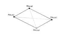
ここで、図3に、物体の領域が平行四辺形で表される場合に、近似楕円を求める方法の一例を示す。図3における点A,B,C,Dが物体の領域である平行四辺形の各頂点である。この場合、まず、辺ABと辺BCのどちらが長いかを計算する。そして、長い方の辺およびその対辺を辺の一部とする最小の長方形を求める。図3の例の場合は点A,B’,C,D’を4頂点とする長方形となる。近似楕円は、例えば、この長方形に内接する楕円と相似で、かつ、点A,B’,C,D’を通る外接楕円とする。
【0061】
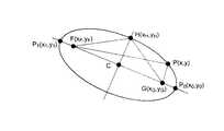
次に、図2(b)において、203は楕円を表現する図形代表点であり、具体的には2つの焦点および1つの楕円上の点(図2(b)の例では短軸上の1点)である。楕円の焦点は2つの軸上の点や楕円の外接矩形から簡単に求めることができる。以下、一例として、図4における長軸上の2点P0,P1および短軸上の1点Hから焦点FとGを求める方法を説明する。
【0062】
まず、長軸と短軸のパラメータであるa,bと、楕円の中心Cと、扁平率eとを、
E(P0,P1)=2×a、
C=(P0+P1)/2、
E(C、H)=b、
e=(1/a)×√(a×a−b×b)
により求める。
ここで、E(P、Q)は点Pと点Qのユークリッド距離である。
【0063】
このようにして求めたパラメータから、焦点FとGは、
F=C+e×(P0−C)、
G=C−e×(P0−C)
により求めることができる。
【0064】
このようにして、楕円の代表点F、GおよびHは決定されるが、これらの点を別のフレームにおいて取り出された楕円の代表点と結びつける際にはあいまいさが生じる。すなわち、抽出された2つの焦点と1つ前のフレームにおける2つの焦点とを結びつける組み合わせは2通り存在する。また、短軸と楕円との交点は2つあるため、1つ前のフレームにおいて抽出された楕円上の一点と対応する交点がどちらなのかがわからない。そこで、これらを決定する方法について説明する。
【0065】
1フレーム前に抽出された2つの焦点をFp、Gpとする。Fpに対応するのがFであるのかGであるのかを判断するために、
E((Gp−Fp)/2,(G−F)/2)と
E((Gp−Fp)/2,(F−G)/2)とを比較する。
前者の方が小さい場合には、FpはFに対応させ、GpはGに対応させる。一方、後者の方が小さい場合には、その逆に、FpはGに対応させ、GpはFに対応させる。
【0066】
また、1つ前のフレームにおける短軸と楕円との交点をHpとし、現フレームの短軸と楕円との2つの交点をH、H’とする。Hpと対応付ける点としてHとH’のどちらを選択するかは2つの距離、
E(Hp−(Gp+Fp)/2,H−(F+G)/2)と
E(Hp−(Gp+Fp)/2,H’−(F+G)/2)とを算出することにより決定する。
前者が小さい場合にはHを選択し、そうでない場合にはH’を選択する。なお、はじめのフレームにおける短軸と楕円との交点Hは2つのうちのどちらを選択してもよい。
【0067】
このように楕円から代表点を抽出する処理は図形代表点抽出部103において行われる。
【0068】
以上の処理によって取り出された代表点は、映像中の注目物体の移動や撮影カメラの移動により、連続するフレームにおいて位置が異なるのが普通である。そこで、対応する楕円の代表点を時系列に並べ、X座標、Y座標ごとにスプライン関数により近似を行う。本実施形態では、楕円の代表点であるF、G、Hの3点(図4参照)それぞれについてX、Y座標のスプライン関数が必要になるので、合計6つのスプライン関数が生成される。
【0069】
以上のスプライン関数による曲線近似は代表点曲線近似部104において行われる。
【0070】
なお、代表点曲線近似部104による処理は、当該物体の領域に関する各フレームの代表点の座標値が得られる毎に行う方法(例えば各フレームの代表点の座標値が得られる毎に近似を行うとともに近似誤差を求め、近似誤差が一定の範囲に収まるように近似区間を適宜分割する方法)や、当該物体の領域に関する全てのフレームの代表点の座標値が得られた後に行う方法などがある。
【0071】
図2(c)の204は近似されたスプライン関数を3次元的に表現したものである。図2(d)の205は代表点曲線近似部104の出力であるスプライン関数の一例である(1つの代表点の1つの座標軸についてのみ示している)。この例は、近似区間がt=0〜5とt=5〜16の2つに分割された場合(節点が3つとなった場合)を示している。
【0072】
このようにして得られたスプライン関数は予め定めておいたデータ形式に従って領域データ記憶部106に記録される。
【0073】
以上のように本実施形態では、映像中の物体の領域を、その近似図形の代表点の時系列的な軌跡(フレーム番号あるいはタイムスタンプを変数とする代表点の座標の軌跡)を近似した曲線のパラメータとして記述することができる。
【0074】
本実施形態によれば、映像中の物体の領域を関数のパラメータのみによって表現できるため、データ量が少なく、ハンドリングの容易な物体領域データを生成することができる。また、近似図形からの代表点の抽出や、近似曲線のパラメータの生成も容易に行うことができる。また、近似曲線のパラメータから近似図形を生成することも容易に行うことができる。
【0075】
また、この近似図形として基本的な図形、例えば一つまたは複数の楕円を用い、例えば楕円を二つの焦点と他の1点により代表させれば、ユーザにより指定された任意の座標が物体の領域(近似図形)内か否か(物体の領域を指示しているか否か)を簡単な判定式により判定することができる。さらに、これによって、ユーザによる映像中の動く物体の指示をより容易にすることができる。
【0076】
以下では、領域データ記憶部106に格納される物体領域データのデータ形式について説明する。なお、ここでは、代表点をスプライン関数により近似する場合を例にとって説明するが、もちろん、代表点を他の関数により近似する場合も同様である。
【0077】
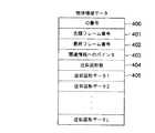
図5に、映像中の物体の領域を表すスプライン関数と、物体に関連付けられた関連情報とを記録するための物体領域データのデータ形式の一例を示す。
【0078】
ID番号400は、物体ごとに付与される識別番号である。なお、このデータは省略されてもよい。
【0079】
先頭フレーム番号401と最終フレーム番号402は、当該ID番号の物体の存在を定義する最初と最後のフレーム番号であり、具体的には、映像中で物体が登場し消えるまでのフレーム番号である。ただし、現実に映像中で物体が登場し消えるまでのフレーム番号ではなく、例えば映像中で物体が登場したときより後の任意のフレーム番号を先頭フレーム番号としてもよいし、また先頭フレーム番号以降でかつ映像中で物体が消えたときより前の任意のフレーム番号を最終フレーム番号としてもよい。なお、先頭/最終フレーム番号は先頭/最終タイムスタンプで代用することもできる。また、最終フレーム番号402は、物体存在フレーム数または物体存在時間に置き換えてもよい。
【0080】
関連情報へのポインタ(以下、関連情報ポインタとも言う)403は、当該ID番号の物体に関連付けられた関連情報データの記録してあるデータ領域のアドレスなどである。関連情報へのポインタ403を使うことにより、物体に関する関連情報を検索したり表示したりすることが容易にできる。また、関連情報へのポインタ403はプログラムや計算機の動作を記述したデータへのポインタであってもよい。この場合には、当該物体がユーザにより指定されると、計算機が所望の動作を行うことになる。
【0081】
なお、関連情報へのポインタ403は、例えば、物体により異なる動作をさせる必要のない場合には、省略することができる。
【0082】
なお、以下の説明では、物体領域データ内に関連情報へのポインタを記述する場合について説明するが、物体領域データ内に関連情報そのものを記述するようにしてもよい。また、物体領域データ内に関連情報へのポインタと関連情報そのものを任意に記述可能としてもよい。この場合には、物体領域データ内に記述されているのが関連情報へのポインタか関連情報そのものかを示すフラグを付加すればよい。
【0083】
近似図形数404は、物体の領域を近似している図形の数である。図2の例においては、一つの楕円で物体領域を近似しているので、図形の数は1となる。
【0084】
近似図形データ405は、近似図形を表現するための図形代表点の軌跡データ(例えばスプライン関数のパラメータ等)である。
なお、近似図形データ405は、近似図形数404に相当する数だけ存在する(近似図形数404が2以上の場合については後述する)。
また、物体領域データにおいて、近似図形数404は常に1つとし(従って近似図形データ405も常に1つとなる)、近似図形数404のフィールドを省くようにしてもよい。
【0085】
次に、図6に、近似図形データ(405)のデータ構造の一例を示す。
【0086】
図形種ID1300は、近似図形としてどのような図形を用いているかを示すためのデータであり、円、楕円、矩形、多角形などを特定する。
【0087】
代表点数1301は、図形種IDで特定される図形を代表する点の数を幾つ必要とするかを表す。
【0088】
1組の代表点軌跡データ1302,1303は、図形の代表点の軌跡を表現するスプライン関数に関するデータ領域である。一つの図形代表点につき、X座標、Y座標のスプライン関数データが必要になる。従って、スプライン関数を特定する代表点軌跡データは、代表点数(M)×2だけ存在する。
【0089】
なお、使用する近似図形の種類を予め1種類、例えば楕円、に限定することも可能である。この場合には、図6の図形種IDのフィールドを省くことも可能である。
【0090】
また、図形種IDによって代表点数が一意に特定される場合には、代表点数を省くことも可能である。
【0091】
次に、図7に、代表点軌跡データ(1302,1303)のデータ構造の一例を示す。
【0092】
接点フレーム番号1400は、スプライン関数の節点を表しており、この節点まで多項式のデータ1403が有効であることを示している。多項式の係数データの数は、スプライン関数の最高次数により変化する(最高次数をKとすると、係数データの数はK+1となる)。そのため、多項式次数1401を参照する。多項式次数1401の後には、多項式次数+1個に相当する数の多項式係数1402が続く。
【0093】
また、スプライン関数は節点間で別の多項式で表現されるため、接点の数に対応した数の多項式が必要になる。従って、節点フレーム番号、多項式の係数などを含むデータ1403は、複数繰り返し記述される。節点フレーム番号が最終フレームと等しくなった場合には、それが最後の多項式係数データであることを意味しているので、代表点軌跡データが終わることがわかる。
【0094】
ここで、近似図形として楕円以外の図形を用いた場合について説明する。
【0095】
図8は、近似図形として平行四辺形を用いた場合の代表点を説明するための図である。点A,B,C,Dが平行四辺形の頂点である。これらのうち3点が決まれば残りの1点も一意に決まるため、代表点としては4頂点のうちの3頂点とすれば十分である。この例では、A,B,Cの3点を代表点としている。
【0096】
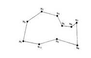
また、図9は、近似図形として多角形を用いた場合の代表点を説明するための図である。多角形の場合には、頂点の順序を外周に沿った順にしておく。図9の例では、10個の頂点を持つ多角形なので、N1〜N10までの全ての頂点を代表点とする。なお、この場合に、内角が180度未満の頂点のみを代表点とするなどして、頂点数を削減するようにしてもよい。
【0097】
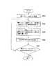
ところで、前述したように、これまで説明してきた処理は、計算機上でソフトウェアにより行うこともできる。図10は本実施形態の情報処理装置の処理の流れの一例を表したフローチャートであり、本実施形態の情報処理装置をソフトウェアにより実現する場合には例えば図10のフローチャートに従ったプログラムを作成すればよい。
【0098】
ステップS11では、映像データから1フレーム分の映像を取り出す。
【0099】
ステップS12では、映像中の特定の物体の領域を抽出する。抽出手法は領域抽出部101と同様の手法を用いることができる。
【0100】
ステップS13では、ステップS12の処理結果である領域情報に対して、近似図形による当てはめを行う。これも領域の図形近似部102と同様の手法を用いることができる。
【0101】
ステップS14では、ステップS13で近似された図形の代表点を抽出する。
【0102】
ステップS15では、連続するフレームにおける近似図形の代表点列の位置の曲線近似を行う。
【0103】
ステップS16は分岐処理で、今処理した画像が最後のフレームか、または処理したフレームにおいて抽出対象の物体が画像中から消失してしまった(もしくは消失したとみなす)場合にはステップS17を、いずれでもない場合にはステップS11の処理へと分岐する。
【0104】
ステップS17では、ステップS15で計算された近似曲線を所定のフォーマットに従って物体領域データとして記録媒体に記録する。
【0105】
さて、これまでは一つの物体に対して一つの図形を割り当てて、物体の領域を大まかに表す例を中心に説明をしてきたが、一つの物体の領域を複数の図形により近似し、近似精度を向上させることも可能である。図11は、一つの物体を複数の図形で近似した例である。この例では画像中の人の領域を600から605までの6つの楕円により表している。
【0106】
一つの物体を図11のように複数の図形で表す場合には、物体を複数の領域に分割する処理が必要となる。この処理にはどのような方法が用いられていても良いが、例えば人手で直接入力する方法がある。この場合、例えば、マウス等のポインティングデバイスを用いて、画像上で領域を矩形や楕円で囲む、あるいはポインティングデバイスの軌跡により領域を指定する、などの操作で実現することができる。また、人手ではなく自動で行う場合には、例えば、物体の動きのクラスタリングで実現する方法がある。これは、連続するフレーム間で物体中の各領域がどのような動きをしたかを相関法(例えば画像解析ハンドブック、第II部第3章、東京大学出版会、1991を参照)や勾配法(例えば、Determining optical flow,B.K.P.Horn and B.G.Schunck,Artificial Intelligence,Vol.17,pp.185−203,1981を参照)などにより求め、これらの動きの似ているものだけをまとめて領域を形成する方法である。
【0107】
このようにして分割された各領域に対しては、それぞれについて図1の構成例や図10の手順例により説明される処理を施すことにより、近似図形データを生成することが可能である。この場合、一つの物体の物体領域データに記述すべきスプライン関数が近似図形の増加に応じて増えることになるため、図12で表されるように近似図形データ405を、近似図形数404に相当する数(この場合、複数)だけ含むデータ構造となる。
【0108】
なお、前述したように物体領域データにおいて近似図形数を常に1つとし(従って近似図形データも常に1つとなる)、近似図形数のフィールドを省くようにする場合において、一つの物体を複数の図形で表すためには、一つの物体を近似する各図形ごとに、物体領域データを生成すればよい(それらは同じID番号を有することになる)。
【0109】
なお、本実施形態では、一つの物体を複数の図形で表す場合に、同一の図形を用いるものとしているが、複数種類の図形を混在して使用可能としてもよい。
【0110】
次に、本実施形態の利用方法のバリエーションについて説明する。映像中の物体としては、通常、人や動物、建物や植物などが考えられるが、映像中のどのようなものに対しても本実施形態の処理を行うことができる。例えば、テロップを映像中の物体として扱うことができるので、以下では物体のバリエーションとしてテロップを対象とした場合の処理について説明する。
【0111】
テロップとは映像中に付帯される文字情報を指す。米国ではクローズドキャプションと呼ばれる文字情報を付帯させることが義務付けられており、日本の放送においてもテロップを多用する傾向にある。表示されるテロップには、静止しているものもあれば、画面下から上へスクロールするもの、画面右から左へスクロールするものなど何らかの動きを伴うものもある。テロップの表示領域を図形近似し、テロップ文字列を関連情報として記憶しておくことにより、映像の内容を簡単に把握したり、所望の映像を検索することが容易に実現できる。
【0112】
領域抽出部101の処理では、人手によりテロップ領域を指定する方法、堀「テロップ認識のための映像からの文字部抽出法」(情報処理学会技術報告99−CVIM−114,pp.129−136,1999)に記されているような文字の輝度値およびエッジ情報を用いて文字列抽出法を行う方法、片山他「ニュース映像のテロップ文字認識に基づく記事分類の精度向上」(画像の認識・理解シンポジウム(MIRU’98)講演論文集、Vol.I,pp.105−110)に記されているようなエッジの強さを調べて背景とテロップを分離する方法などを用いて、テロップ領域の抽出を行う。得られたテロップ領域からは、各文字あるいは各文字列を切り出すこともできる。また、連続したフレームでテロップ領域内のエッジ情報を比較し、テロップの出現フレームおよび消滅フレームを検出する。
【0113】
領域図形近似部102の処理では、領域抽出部101で抽出されたテロップ領域を矩形で近似する。テロップが出現したフレームの番号を物体領域データの先頭フレーム番号(図4もしくは図12の401)に、消滅したフレームを最終フレーム番号(402)に格納する。関連情報へのポインタ(403)にはテロップの文字列情報へのポインタを格納し、近似図形データ(405)としてテロップを囲む矩形領域情報を保持する。複数行のテロップの各行を別々の領域とする場合や各文字を別々の領域とする場合には、行数または文字数を近似図形数(404)に格納し、それぞれの行あるいは文字を囲む矩形領域データすなわち近似図形データ(405)を該当数だけ格納する。
【0114】
図形代表点抽出部103および代表点曲線近似部104での処理は、テロップに特化したものはなく、前述の通りである。
【0115】
関連情報記憶部105には、登場するテロップの文字列情報を保存しておき、その情報へのポインタをテロップ領域データ(物体領域データ)が保持する。
【0116】
以上により、キーワードを入力し、それに合致あるいは関連する文字列がテロップの文字列情報の中にあれば、その文字列が出現するフレームや時刻を容易に知ることができ、ニュース番組であれば、興味のある記事を検索し、その部分だけを鑑賞することも可能となる。
【0117】
なお、この場合には、テロップの文字列情報に、そのフレームや時刻に対応する物体領域データへのポインタを付加するようにすれば、検索をより容易にすることができる。
【0118】
以上、テロップを対象とした場合の処理について説明したが、本実施形態の利用方法やどのようなものを対象物体とするかについては、他にも様々なバリエーションが考えられる。
【0119】
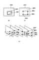
さて、図2の例では、楕円による近似方法を一例として説明を行ったが、以下では、近似方法の他の例として、矩形による近似方法について説明する。
【0120】
図13は、図2と同じ形式の図であるが、ここでは、領域図形近似部102として領域の矩形による近似方法を用い、図形代表抽出部103として矩形の4つの頂点を抽出する方法を用い、代表点曲線近似部104としてスプライン関数による近似方法を用いた場合を例としている。
【0121】
図13(a)において、2800は処理対象となっている映像中の1フレームを示している。
【0122】
2801は抽出対象となっている物体の領域を示している。この物体の領域2801を抽出する処理は領域抽出部101において行われる。
【0123】
2802は物体の領域を矩形で近似したものである。物体領域2801から矩形2802を求める処理は領域図形近似部102において行われる。
【0124】
ここで、例えば図13(a)において矩形2802を求める場合の処理手順の一例を図14に示す。すなわち、フレーム2800のマスク画像を例えばラスタースキャンし(ステップS60)、対象画素が物体領域内であるときに(ステップS61)、X座標とY座標のそれぞれについて、それまで保存されている最小値より小さい場合には最小値を更新し、それまで保存されている最大値より大きい場合には最大値を更新する(ステップS62)ことを、全ての画素について繰り返しチェックすることによって、X座標とY座標のそれぞれについて物体領域を示す画素位置の最小値および最大値を求めれば、矩形2802の4つの頂点座標を得ることができる。
【0125】
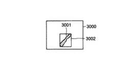
このような方法は処理が簡易な点で優れているが、例えば図15のように細長い物体3001が画面3000に対して斜めの姿勢で存在しているときには、近似矩形3002内には非物体領域が特に多く含まれてしまう。また、細長い物体物体が回転すると矩形2802の大きさ、形状が変化する。これらは、物体指定する際の弊害となる場合がある。
【0126】
そこで、矩形の大きさができるだけ小さくなり(近似矩形内の非物体領域ができるだけ少なくなり)、対象物体の姿勢も反映させることのできる近似方法の一例を示す。
【0127】
図16(a)において、3100は処理対象となっている映像中の1フレームを示している。
【0128】
3101は抽出対象となっている物体の領域を示している。この物体の領域3101を抽出する処理は領域抽出部101において行われる。
【0129】
3102は物体の領域を矩形で近似したものである。この近似矩形は図13(a)の矩形2802とは異なり、傾きを持っている。矩形内の非物体領域も少なく、対象が回転してもその形状は一定である。物体領域3101から矩形3102を求める処理は領域図形近似部3102において行われる。
【0130】
図17に、この場合の処理手順の一例を示す。この処理手順例は、対象物体領域の慣性主軸を求め、これに基づいて近似図形を求めるようにしたものである。
【0131】
図16(b)において、3103は、対象物体領域の重心を示している。
【0132】
3104は、対象物体領域の慣性主軸を示している。3105は、3104に垂直な直線である。
【0133】
まず、対象物体領域の慣性モーメントm20、m02、m11を求める(ステップS70〜S72)。
【0134】
マスク画像をf(x,y)とすると、f(x,y)は領域内では1で、領域外では0である。対象領域の慣性モーメントは、
mij=ΣΣxiyjf(x,y)
で表せる。
【0135】
ここで、原点を通る直線y=x tanθについてのf(x,y)の慣性モーメントは、
mθ=∬(x sinθ−y cosθ)2f(x,y)dxdy
で得られる。
θを変化させたときにmθを最小にする角度をθ0とする。一通りの角度しかないとき、直線y=x tanθ0を慣性主軸と呼ぶ。
tanθ0は、2次方程式、
tan2θ+{(m20−m02)/m11}tanθ−1=0
の解として求まる。
これにより重心3103の周りでtanθ0を求めると、対象物体の慣性主軸が得られる(ステップS73)。
【0136】
次に、慣性主軸に平行で物体領域に外接する直線と、慣性主軸に垂直で物体領域に外接する直線を求める(ステップS74)。
図16(b)において、直線3106,3107は、慣性主軸3104に並行な直線であり、対象物体領域に外接する。
直線3108,3109は、直線3105に平行な直線であり、対象物体領域に外接する。
矩形3102は、直線3106,3107,3108,3109によって形成される(ステップS75)。
【0137】
なお、対象物体が円の場合には慣性主軸が求まらないが、このような場合には例えば図14で説明した手順で近似矩形を求めればよい。
【0138】
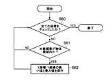
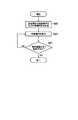
ところで、矩形より楕円で物体領域を表現する方が適当な場合もある。図18に、物体の領域が矩形で表される場合に、その矩形から近似楕円を求める方法の一例を示す。図19に、この場合の処理手順の一例を示す。
【0139】
図18において、対象物体領域3300と外接矩形3301が得られているものとする。
【0140】
まず、近似矩形の内接楕円および外接楕円を求める(ステップS80)。
【0141】
図18において、楕円3302は矩形3301の内接楕円であり、楕円3303は矩形3301の外接楕円である。
【0142】
次に、内接楕円3302の大きさを少しずつ外接楕円3303に近づけていき(ステップS81)、物体領域を全て包含する楕円3304を求め(ステップS82)、近似楕円とする。なお、繰り返し処理において、一回に内接楕円3302の大きさを拡大する単位は、予め定めておいてもよいし、内接楕円3302の大きさと外接楕円3303の大きさの差分に応じて決定してもよい。
【0143】
また、上記とは逆に、外接楕円3303の大きさを内接楕円3302に近づけていってもよい。この場合には、外接楕円3303は最初から物体領域を全て包含しているので、例えば、繰り返し処理において、始めて物体領域に包含されない部分を生じた楕円の、一回前における楕円を、近似楕円とすればよい。
【0144】
次に、図形代表点抽出部103では、近似矩形や近似楕円の代表点を求める。矩形の代表点は4つもしくは3つの頂点を代表点とすることができ、楕円の場合は楕円の外接矩形の頂点としたり、2つの焦点と楕円上の一点としたりすることができる。
【0145】
次に、代表点曲線近似部104では、時系列的に得られている代表点の軌跡をスプライン関数などで近似する。このとき、時系列同士の対応付けが重要である。例えば、近似図形が矩形で代表点を頂点とする場合には、隣接するフレーム間で頂点同士の対応付けを行う必要がある。
【0146】
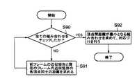
図20に、対応付け方法の一例を示す。また、図21に、対応付け処理の手順の一例を示す。
【0147】
図20において、3500は近似矩形の重心である。前のフレームにおける矩形3501と現在のフレームにおける矩形3502が得られている。矩形3501と3502のいずれかを平行移動させ、重心位置を一致させる(重心位置を一致させた状態が図20である)。次に、それぞれの矩形の頂点同士の距離d1〜d4を計算し、全ての頂点の組み合わせで距離の和を求める(ステップS90,S91)。距離の和が最小となる組み合わせを求め、対応付けする(ステップS92)。
【0148】
近似図形から代表点を得る際に、一定の規則で代表点を取得しておくと、組み合わせの数を削減することが可能である。例えば、矩形では時計周りに頂点座標を代表点として保存するようにすると、対応付けの組み合わせは4通りで済む。
【0149】
なお、この方法では対応付けが難しい場合がある。例えば、近似矩形が隣接フレームにおいて正方形に近い形状であり且つ45度回転移動している場合には、対応付けが難しい(2通りの組み合わせにおいて距離の和が同じような値になる)。そこで、このような場合には、例えば、近似矩形内の物体領域同士の排他的論理和を取り、その面積が最小となる組み合わせを採用する方法、あるいは物体領域のテクスチャの絶対差分を求め、差分値が最小となる組み合わせを求める方法などを用いればよい。
【0150】
続いて、以下では、本発明を適用して物体領域の軌跡を記述する際に、図6、図7で例示した近似データ構造とは別の構造を用いる例について説明する。
【0151】
図22は、近似図形データおよび物体領域の代表点軌跡データの記述フォーマットの他の例である。なお、図22では、代表点軌跡データの部分については、1つの代表点についてのみ示してある(実際には、代表点の個数に対応して記述される)。
【0152】
ここでは、多項式の最高次数を2次として説明する。
【0153】
前述した例(図5、図6、図7)では、多項式スプライン関数の全ての係数を記述していたのに対して、ここでの記述方法では、スプライン関数の節点の座標と、スプライン関数の2次の係数に関連する値との組み合わせにより記述する。この記述方法の利点は、節点が容易に取り出せるため、大まかな物体の軌跡が簡単にわかるという点である。
【0154】
以下、この記述方法について詳細に説明する。
【0155】
図22中、図形種ID(3900)は、物体の形の近似に用いた図形の種類を特定する。例えば、物体の重心のみ(CENTROID)、矩形(RECTANGLE)、楕円(ELLIPSE)や、それらの組み合わせを指定できる。図23は、図形の種類と図形種IDの割り当て例である。また、代表点数3901は、図形の種類によって定まる代表点軌跡の数を表す。
【0156】
節点数(N)3902は、代表点軌跡を表すスプライン関数の節点の数を表す。各節点に対応するフレームは、時間として表され、節点時刻3903に格納される。節点時刻は、設定数だけあるため、配列として記述しておく(3904)。
【0157】
同様に、各節点のx座標、y座標もそれぞれ節点X(3905)および節点Y(3907)の配列(3906,3908)として記述される。
【0158】
一次関数フラグ3909は、節点間のスプライン関数として一次関数だけが用いられているかどうかを表す。一部分でも2以上の多項式を用いる場合には、このフラグはオフにしておく。このフラグを用いることにより、近似関数として一次関数のみに使われる場合に以下で説明する関数特定情報3910を1つも記述しなくて済むため、データ量を削減できるというメリットがある。なお、必ずしもこのフラグは必要ではない。
【0159】
関数特定情報に含まれる関数ID(3911)、関数パラメータ(3912)はそれぞれ多項式スプライン関数の次数と、その係数を特定するための情報を表す。図24に、それらの一例を示す。ここで、ta,tbは連続する節点の時刻、f(t)は[ta,tb]の区間のスプライン関数、fa,fbは時刻ta,tbにおける節点の座標を表している。1次多項式を用いるときは節点のみの情報で十分なので、関数パラメータは記述されていないが、2次多項式の場合には係数を特定するための情報として一つの値が関数パラメータに記述される。なお、図24の例では、2次の係数が用いられているが、例えば、二次曲線上のfa,fb以外の1点など、他の値を用いることもできる。
【0160】
本記述方法では、節点の情報と関数パラメータの情報により、図24の制約条件を用いて全ての区間におけるスプライン関数が再現できる。
【0161】
関数特定情報は、(節点数−1)に相当する個数のものが存在し、これらは配列となって記述される(3913)。
【0162】
なお、上記では、多項式の最高次数を2次として説明したが、もちろん、多項式の最高次数を3次以上とすることも可能である。
【0163】
続いて、以下では、関連情報のバリエーションを示す。
【0164】
図25は、主として監視映像に用いられる関連情報のデータ構造の一例を示す。実際のデータはこれらの項目のうち、少なくとも一つを含めればよい。
オブジェクト種4201は、“車両”や“人”など、近似されている物体の種類を示すデータである。
識別情報4202は、“人名”や“車両のナンバー”、“車種”など、実際の物体を識別するためのデータである。
動作内容4203は、“歩く”や“走る”などの物体の動作を示すデータである。
【0165】
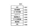
図26は、主として商用コンテンツやハイパーメディア・コンテンツなどに用いられる関連情報のデータ構造の一例を示す。実際のデータはこれらの項目のうち、少なくとも一つを含めればよい。
名前4301は、物体の名前を示すデータである。物体が映画などに登場する人物である場合は、役者や俳優の名前を特定する。
著作権情報4302は、物体の著作権者などの著作権に関わる情報を示すデータである。
コピー許可情報4303は、物体を近似する図形に含まれる範囲の映像情報を切り出して再利用することを許可するか否かを示すデータである。
フットマーク4304は、物体が最後に編集された日時を示すデータである。
関連情報のURL4305は、ハイパーリンクを用いて、物体の関連情報を表示するときに参照すべきデータをURLによって表現したものである。
アクセス制限情報4306は、物体ごとに視聴やハイパーリンクによるジャンプの許可/不許可の情報や許可条件を設定するためのデータである。
課金情報4307は、物体ごとの課金情報を示すデータである。
注釈データ4308は、物体の関連情報や操作の手助けとなるデータである。
【0166】
なお、図25や図26の関連情報は、物体領域データ内に記述すると好ましい。
【0167】
次に、映像データや物体領域データの提供方法について説明する。
【0168】
本実施形態の処理により作成された物体領域データがユーザの用に供される場合には、作成者側からユーザ側に何らかの方法で物体領域データを提供する必要がある。この提供の方法としても以下に例示するように種々の形態が考えられる。
(1)映像データとその物体領域データとその関連情報とを1つ(または複数の)記録媒体に記録して同時に提供する形態
(2)映像データとその物体領域データとを1つ(または複数の)記録媒体に記録して同時に提供するが、関連情報は別途提供するかもしくは提供しない(後者は例えば提供しなくてもユーザがネットワーク経由等で別途取得できる場合)形態
(3)映像データを単独で提供し、別途、物体領域データと関連情報とを1つ(または複数の)記録媒体に記録して同時に提供する形態
(4)映像データ、物体領域データ、関連情報を別々に提供する形態
上記は主に記録媒体により提供する場合であるが、その他にも、一部または全部を通信媒体で提供する形態も考えられる。
【0169】
(第2の実施形態)
第1の実施形態では映像中の物体の領域を近似する図形の代表点を抽出し、物体領域データへの変換を行ったが、第2の実施形態は、映像中の物体領域中の特徴点を抽出し、物体領域データへ変換するようにしたものである。
【0170】
本実施形態では、第1の実施形態と相違する点を中心に説明する。
【0171】
図27に、本実施形態に係る物体領域データ変換装置の構成例を示す。図27に示されるように、本物体領域データ変換装置は、映像データ記憶部231、特徴点抽出部233、特徴点の曲線近似部234、関連情報記憶部235、領域データ記憶部236を備えている。
【0172】
図27において、映像データ記憶部230は第1の実施形態の映像データ記憶部100と、関連情報記憶部235の第1の実施形態の関連情報記憶部105と、領域データ記憶部236は第1の実施形態の領域データ記憶部106とそれぞれ同じ機能を持つものである。
【0173】
特徴点抽出部233は、映像中の物体領域から特徴的な点を1つ以上取り出す。特徴点としては、種々のものが考えられるが、例えば、物体の角(例えば、Gray−level corner detection,L.Kitchenand A.Rosenfeld,Pattern RecognitionLetters,No.1,pp.95−102,1982による方法など)、物体の重心などが考えられる。
【0174】
特徴点の曲線近似部(以下、特徴点曲線近似部)234は、基本的には第1の実施形態における代表点曲線近似部104と同様の機能を持つ。すなわち、特徴点抽出部233で抽出された特徴点の位置を時系列で曲線に近似する。この近似曲線は、X座標、Y座標ごとにフレーム番号fもしくは映像に付与されているタイムスタンプtの関数として表現され、直線近似やスプライン曲線による近似などで曲線に近似される。近似後のデータの記録方法は第1の実施形態と同様である。
【0175】
また、本実施形態における物体領域データは基本的には第1の実施形態の物体領域データ(図5)と同様である。ただし、近似図形数のフィールドは不要である。また、「近似図形データ」が「特徴点データ」となる。
【0176】
物体領域データの中の特徴点データも基本的には第1の実施形態の近似図形データ(図6)と同様である。ただし、「代表点数」が「特徴点数」となり、「代表点軌跡データ」が「特徴点軌跡データ」となる。また、図形種IDは不要である。
【0177】
特徴点データの中の特徴点軌跡データは第1の実施形態の代表点軌跡データ(図7)と同様である。
【0178】
図28に本実施形態の物体領域データ変換装置の処理の流れの一例を表したフローチャートを示す。全体的な流れとしては第1の実施形態と同様で、図10のステップS12〜S14の部分を特徴点の抽出とし、ステップS15の部分の代表点を特徴点としたものである。
【0179】
もちろん、本実施形態もソフトウェアによっても実現可能である。
【0180】
以上のように本実施形態では、映像中の物体の領域を、その特徴点の時系列的な軌跡(フレーム番号あるいはタイムスタンプを変数とする特徴点の座標の軌跡)を近似した曲線のパラメータとして記述することができる。
【0181】
本実施形態によれば、映像中の物体の領域を関数のパラメータのみによって表現できるため、データ量が少なく、ハンドリングの容易な物体領域データを生成することができる。また、特徴点の抽出や、近似曲線のパラメータの生成も容易に行うことができる。
【0182】
また、本実施形態によれば、ユーザにより指定された任意の座標が物体の領域を指示しているか否かを極めて簡単に判定することができる。さらに、これによって、ユーザによる映像中の動く物体の指示をより容易にすることができる。
【0183】
ところで、第1の実施形態の物体の領域の近似図形の代表点をもとにした物体領域データと、第2の実施形態の物体の領域の特徴点をもとにした物体領域データとを混在して使用可能とすることもできる。
この場合には、例えば、物体領域データのフォーマットとしては第1の実施形態のものに、物体の領域の近似図形の代表点をもとにしたものかあるいは物体の領域の特徴点をもとにしたものかを識別するフラグを設ければよい。あるいは、第1の実施形態の物体領域データのフォーマットにおいて、該フラグを設けるのではなく、例えば、図形種IDが特定の値のときに、物体の領域の特徴点をもとにしたものであることを示すものとし、それ以外のときに、物体の領域の近似図形の代表点をもとにしたものであることを示すものとしてもよい。
【0184】
さて、これまでは、物体領域データの構造とそれを作成する側について説明してきたが、以下では、このような物体領域データを利用する側について説明する。
【0185】
(第3の実施形態)
第3の実施形態では、映像中の物体に関連情報を含む物体領域データが付与されている場合に、ユーザが(主にGUI画面上で)物体を指示することにより、関連情報を呈示(文字、静止画、動画等の表示、音声の出力等)させ、あるいは関連するプログラムを実行させるような場合について説明する。
【0186】
図29に、本実施形態に係る情報処理装置の構成例を示す。図29に示されるように、本情報処理装置は、映像データ表示部301、制御部302、関連情報呈示部303、指示入力部304を備えている。
【0187】
映像データ表示部301は、図示しない記録媒体等から入力した映像データを液晶表示装置もしくはCRT等に表示するためのものである。
【0188】
指示入力部304は、ユーザがマウス等のポインティングデバイスもしくはキーボードなどを用いて、液晶表示装置もしくはCRT等に表示された映像中の物体を指示するなどの操作を行うことを可能とし、そのユーザからの入力を受け付けるためのものである。
【0189】
制御部302は、詳しくは後述するが、例えばユーザが画面上で指示した座標と図示しない記録媒体等から入力した物体領域データとに基づいてユーザが映像中の物体を指示したか否か判定するとともに、ユーザが映像中のある物体を指示したと判定された場合に、物体領域データの関連情報へのポインタを参照し、その物体の関連情報を取得させ、これを呈示させる制御等を行うためのものである。
【0190】
関連情報呈示部303は、制御部302からの指示に応じて、関連情報を(記録媒体やネットワークを介したサーバ等から)取得し、呈示するためのものである。
【0191】
なお、関連情報へのポインタがプログラムや計算機の動作を記述したデータへのポインタである場合には、当該計算機が所望の動作を行うことになる。
【0192】
もちろん、本実施形態もソフトウェアによっても実現可能である。
【0193】
次に、第1の実施形態のように物体の領域が近似図形として表現されている場合に対応する処理手順について説明する。
【0194】
図30に、本処理手順の一例を示す。ただし、図30のフローチャートでは、映像の再生中に表示されている映像内をマウスカーソル等のポインティングデバイスを用いて指示された際の処理についてのみ示している(基本的には制御部302の処理に相当するものである)。
【0195】
ステップS31では、ポインティングデバイス等により指示された画面上の座標が、映像中の画像のどこに相当するかを計算する。さらに、指示された瞬間に再生を行っていた映像のフレーム番号を取得する。なお、フレーム番号ではなく、タイムスタンプを用いてもよい(以下では、フレーム番号として説明する)。
【0196】
ステップS32では、映像に付随している映像中の物体の物体領域データから、物体が指示されたフレーム番号において映像中に存在している物体のみを選択する。これは、物体領域データにおける先頭フレーム番号および末尾フレーム番号を参照することにより容易に実行できる。
【0197】
次に、ステップS33では、物体領域データから取り出したスプライン関数データ(図6、図7参照)を用いて、物体が指示された際の映像表示フレーム番号における近似図形の代表点の座標を算出する。これにより、例えば第1の実施形態の例(図2/図4)においては楕円の二つの焦点FとGおよび楕円上の点Hが求まる。
【0198】
ステップS34では、上記で求められた代表点と物体領域データの図形種IDに応じて定まる判定手順に基づいて、ポインティングデバイス等により指示された座標が、物体(すなわち、近似図形)の内部か否かを判定する。
【0199】
第1の実施形態で説明したように楕円を2つの焦点と1つの楕円上の点により代表させている場合には簡単に判定ができる。
【0200】
例えば、第1の実施形態と同様に、E(P、Q)により点Pと点Qのユークリッド距離を表すことにすれば、
ポインティングデバイスにより指示された座標Pが楕円内部である場合には、
E(F、P)+E(G、P)≦E(F、H)+E(G、H)が成り立つ。
【0201】
楕円外部である場合には、逆に、
E(F、P)+E(G、P)>E(F、H)+E(G、H)となる。
このような不等式を用いて、指示された点が物体内部か外部かを判定し、その判定結果によりステップS35を行うか否かを決定する。
【0202】
また、映像中の物体領域の近似図形として平行四辺形を用いている場合には、楕円の場合のような一つの不等式ではなく、4つの不等式を用いて任意の座標が物体の内部かどうかを判定する。
【0203】
例えば、図8のA,B,C点を代表点としている場合、点Dを、
D=C+A−Bにより求める。
次に、点Aと点Bを通る直線上の点をQとし、直線式を、
fA,B(Q)=0で表すことにする。
点Pが図形内部にあるときは、2つの不等式、すなわち、
fA,B(P)*fC,D(P)<0、
fB,C(P)*fD,A(P)<0
が同時に成り立つ。
ただし、
fA,B(P)=(yA−yB)*(x−xA)−(xA−xB)*(y−yA)
fB,C(P)=(yB−yC)*(x−xB)−(xB−xC)*(y−yB)
fC,D(P)=(yD−yC)*(x−xC)−(xD−xC)*(y−yC)
fD,A(P)=(yA−yD)*(x−xD)−(xA−xD)*(y−yD)
とし、
P=(x,y)、A=(xA,yA)、B=(xB,yB)、C=(xC,yC)、D=(xD,yD)とした。
【0204】
なお、1つの物体が複数の近似図形で近似されている場合には(図5/図12の近似図形数参照)、上記の処理は各近似図形について行われる。
【0205】
ステップS35は、指示された点が物体領域内である場合にのみ行われる処理である。この場合、物体領域データに含まれている「関連情報へのポインタ」を参照し、このポインタ情報に基づいて関連情報を取得し、その表示等を行う(図29の構成例では、これを関連情報呈示部303により行う)。また、関連情報としてプログラムが指定されている場合には、指定プログラムを実行したり、またその他、指定されている所定の動作を行う。なお、物体領域データに関連情報そのものが記述されている場合にはこれを表示等すればよい。
【0206】
図31に、関連情報として映像中の物体の説明が付与されている場合の一例を示す。映像800の再生中にポインティングデバイス802により指示された座標が物体801(を近似した図形の)領域内部であった場合、関連情報803が表示される。
【0207】
ステップS36は、分岐処理であり、物体を指示されたフレームにおいてまだ他に物体領域データを持つ物体が存在しているかを判定し、存在している場合にはステップS32へ処理を進め、そして存在しない場合には終了となる。
【0208】
次に、第2の実施形態のように物体の領域がその物体の特徴点として表現されている場合に対応する処理手順について説明する。
【0209】
ここでは、上記した第1の実施形態のような場合に対応するものとの相違点を中心に説明する。
【0210】
図32に、本処理手順の一例を示す。ただし、図32のフローチャートでは、映像の再生中に表示されている映像内をマウスカーソル等のポインティングデバイスを用いて指示された際の処理についてのみ示している(基本的には制御部302の処理に相当するものである)。全体的な流れとしては図30のフローチャートと同様であるので、ここでは相違する点を中心に説明する(ステップS41,S42,S45,S46は、それぞれ、ステップS31,S32,S35,S36と同様である)。
【0211】
ステップS43では、物体領域データから表示フレーム番号における物体の特徴点の位置座標を算出する。特徴点が複数ある場合には、全ての特徴点の座標を算出する。
【0212】
ステップS44では、ステップS43で算出された特徴点の位置とクリックされた座標との間の距離を、全ての特徴点について計算し、予め決められているしきい値よりも距離が小さい特徴点が1つ以上存在するか1つも存在しないかを判定する。あるいは、上記距離をある特徴点について計算し、それを予め決められているしきい値と比較する処理を繰り返し行い、該しきい値よりも距離が小さい特徴点が1つ見つかれば、その時点でこの処理をうち切るようにしてもよい。該しきい値よりも距離が小さい特徴点が1つ以上存在する場合にはステップS45へ処理を進め、存在しない場合にはステップS46へと処理を進める。
【0213】
このような処理により、物体の領域付近がポインティングデバイス等により指定された場合に、物体の特徴点座標から関連情報の表示を行うことができる。
【0214】
(第4の実施形態)
次に、第4の実施形態として、関連情報の表示等が可能な物体の領域を物体領域データを用いて明示的に表示する(ユーザに知らしめる)場合について説明する。この場合、関連情報の表示等が可能な物体には、関連情報ポインタを含む物体領域データが予め付与されている必要がある。
【0215】
本実施形態のブロック構成は例えば第3の実施形態(図29)と同様である。
【0216】
もちろん、本実施形態もソフトウェアによっても実現可能である。
【0217】
以下、第1の実施形態のように物体の領域が近似図形として表現されている場合について説明する。
【0218】
図33に、本実施形態における処理手順の一例を示す。
【0219】
ここでは、近似図形が楕円である場合を例にとって説明する。もちろん、他の近似図形の場合にも同様である。
【0220】
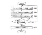
ステップS51では、現在表示中の映像のフレーム番号を取得する。なお、フレーム番号ではなく、タイムスタンプを用いてもよい(以下では、フレーム番号として説明する)。
【0221】
ステップS52では、ステップS51で取得したフレーム番号において映像中に存在している物体を選択する。これは、映像に付与されている物体領域データの先頭フレーム番号と末尾フレーム番号の間に表示フレーム番号があるデータを見つけることにより行われる。
【0222】
次に、ステップS53では、ステップS52で選択された物体の物体領域データからスプライン関数データ(図6、図7参照)を取り出し、表示フレームにおける図形の代表点の座標を算出する。
【0223】
ステップS54では、物体領域データの図形種IDを参照してステップS53で算出された代表点で表現される近似図形を求め、該近似図形(例えば楕円領域)内の画像表示を変更する。
【0224】
この変更方法には様々な方法が適用可能である。例えば、近似図形が楕円である場合、その楕円領域内の画像の輝度を予め定められた値だけ増加させる。この増加分をΔY、表示変更前の輝度をY、表示可能な輝度の上限をYmaxとしたとき、楕円内の画素はMIN(Y+ΔY,Ymax)の輝度で表示を行い、楕円外の画素は輝度Yで表示を行う。ここでMIN(a,b)はa、bのうちの小さい方の値をとる関数である。
【0225】
図34はこのような輝度を増加させる方法で物体領域を表示させた例である(なお、図34においてハッチングされた部分は輝度の変更がなく、ハッチングされた部分は輝度が増加されたことを示している)。図34(a)の画面1000は表示中のフレームでステップS54の表示変更処理前の表示状態であり、1001は映像中の物体領域データを持つ物体を表している。図34(b)の画面1002はステップS54の表示変更後の表示で、1003は物体1001の領域を近似した楕円領域である。楕円領域1003内だけ表示が明るくなり、関連情報の表示等が可能な物体であることがわかるようになっている。
【0226】
なお、1つの物体が複数の近似図形で近似されている場合には(図5/図12の近似図形数参照)、上記の処理は各近似図形について行われる。
【0227】
ステップS55は表示変更を行うべき物体が他にあるかどうかを判定する処理で、表示フレーム番号が物体領域データの先頭フレーム番号と末尾フレーム番号の間となっている未処理の物体があるかどうかを調べる。未処理の物体が存在する場合にはステップS52から処理を繰り返し、存在しない場合には処理を終了する。
【0228】
このように、本物体領域データを用いて特定される映像中の物体の領域のうち、関連情報を持つ物体の領域の表示を変更することにより、関連情報があるかないかを一目で確認することが可能になる。
【0229】
関連情報の表示等が可能な物体の領域を明示的に示す方法としては、以上説明したような物体の領域内の輝度を変化させる方法の他に、様々な方法を用いることができる。以下、そのいくつかのバリエーションを示す。なお、以下の物体領域データを用いる各処理の手順は、基本的には図33のフローチャートと同様で、ステップS54を各々の該当する処理に変更すればよい。
【0230】
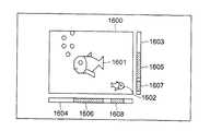
図35に例示する表示方法は、画像1600の外に関連情報を持つ物体の位置を表示する方法である。1601および1602が関連情報を持つ物体である。1603および1604はそれぞれ縦軸方向、横軸方向の物体の位置を表示するバーである。関連情報を持つ物体1601に対応する表示が1605および1606である。これらは、1601の領域を縦軸方向、横軸方向に射影した領域に、目印となるバーを表示したものである。同様に、1602に対しては1607,1608が領域を表示するバーである。
【0231】
物体の領域の各方向への射影は、これまでの実施形態で説明したようにして物体領域データの近似図形データから求めた当該フレームでの近似図形の代表点の座標と、図形種IDとから、容易に求めることができる。
【0232】
なお、異なる物体に対しては、領域を示すバーは異なる表示形態(例えば異なる色)を用いるようにすると好ましい。
【0233】
本方法によれば、ユーザは1603と1604に表示されたバーに合わせて画像内をポインティングデバイスで指定することにより、関連情報を表示させることができる。
【0234】
図36に例示する表示方法は、画像1700の外に関連情報を持つ物体の位置を表示する他の方法である。画像1700の中に関連情報を持つ物体1701および1702が存在している。縦方向と横方向の関連情報を持つ物体位置表示バー1703と1704に物体の位置が表示される。図35の例と異なり、表示バーには物体の重心位置のみが表示される。1705および1706は物体1701の重心位置を表示している。また、1707および1708は物体1702の重心位置を表示している。
【0235】
物体の領域の各方向の重心も、これまでの実施形態で説明したようにして物体領域データの近似図形データから求めた当該フレームでの近似図形の代表点の座標と、図形種IDとから、容易に求めることができる。
【0236】
本方法によれば、物体の大きさが大きい場合でも、物体位置表示バー上での表示が小さいため、見やすい表示となる。また、多くの物体位置を表示する場合にも同様に見やすい表示となる。
【0237】
図37に例示する表示方法は、画像1800の外に関連情報リストを表示する方法である。画像1800に関連情報を持つ物体1801および1802が含まれている。1803は関連情報を持つ物体のリストである。このリストには、現在表示中の画像フレームにおいて、関連情報を持つ物体の情報が表示される。図37の例では、物体の名称が表示されているが、これは、当該フレーム中に存在する物体の物体領域データから関連情報をたどった結果、得られたものである。
【0238】
本方法によれば、ユーザは1801または1802の領域をポインティングデバイスで指定するほか、リストに表示された名称を指定しても関連情報を表示させることができる。また、1803のリストに表示されている番号を指定しても関連情報が表示できるように構成可能であるため、リモコンなどポインティングデバイスがない場合でも対応可能である。
【0239】
図38に例示する表示方法は、画像1900の中の関連情報を持つ物体1901および1902をアイコンにより表示し、関連情報があることを示す方法である。アイコン1903が物体1901に、そしてアイコン1904が物体1902に対応している。
【0240】
上記のアイコンについては、例えば、これまでの説明のようにして近似図形を求め、当該フレームの映像データ中から該求めた近似図形を内包する所定の大きさの矩形の領域を切り出し、該切り出した矩形の領域を適宜縮小するなどして、アイコンとして表示すればよい。
【0241】
本方法によれば、映像中の物体の領域を指定するほか、アイコンを直接指定しても関連情報の表示が行える。
【0242】
図39に例示する表示方法は、関連情報を持つ物体の領域を示すマップの表示により、関連情報の存在を示す方法である。画像2000に関連情報を持つ物体1901および1902が含まれている。2003は関連情報を持つ物体領域マップであり、マップは画像2000の中のどこに関連情報を持つ物体領域があるかを示している。2004は物体2001を、2005は物体2002を表している。
【0243】
マップ2003は、画像2000を縮小したものであり、物体領域以外の画像表示は行わない(前述のようにして求めた近似図形のみ、縮小画像中の該当する位置に表示する)。
【0244】
なお、異なる物体に対しては、領域を示すバーは異なる表示形態(例えば異なる色)を用いるようにすると好ましい。
【0245】
本方法によれば、画像2000中の物体を直接指定する他、マップ2003上で表示されている物体領域を指定しても、関連情報の表示等を行うことができる。
【0246】
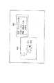
図40に例示する表示方法は、画像中の関連情報を持つ物体をポインティングデバイスで指定することを容易にするために、映像再生をマウスカーソルの位置でコントロールするようにした方法である。2100および2102は表示画面全体を表しており、2101および2103は表示画面上の画像が表示されている領域を表している。図40(a)の表示画面2100においてはマウスカーソル2104が画像2101の領域外にあるので、画像を通常の表示速度で再生させる。一方、図40(b)の表示画面2102ではマウスカーソル2105が画像領域2103の中に入っているので、画像の再生速度を遅くする、もしくは静止させる。
【0247】
なお、マウスカーソルが画像領域内に入った場合に、当該フレーム内に関連情報を持つ物体が存在するか否かを調べ(例えば当該フレーム番号と各物体領域データの先頭/最終フレーム番号を比較して調べる)、当該フレーム内に関連情報を持つ物体が存在するときだけ、画像の再生速度を遅くする、もしくは静止させるようにしてもよい。
【0248】
例えば映像中で高速に動いている物体をマウスカーソルで指定するのは難しい場合があるが、本方法によれば、このようにマウスカーソルの位置により再生速度を変化させることで、物体指定時の物体の動きを遅くさせもしくは静止させることができ、指定が容易になる。
【0249】
図41に例示する表示方法は、画像中の関連情報を持つ物体をポインティングデバイスで指定することを容易にするための他の方法ある。2500は再生されている映像である。2501は画像を獲得するポインタであり、このボタンをマウスポインタ2502で指定すると、指定された時点で表示されていた画像が獲得され、獲得画像表示部2503に表示される。2500は2501指定後も再生が続けられる。しかし、獲得画像はしばらく2503に表示されるため、2503内に表示されている物体を指定することにより、指定された物体の関連情報を表示させることができる。
【0250】
なお、画像を獲得するボタン2501は必ずしも必要ではなく、2501を設けずにマウスカーソルが映像表示部2500内に入ったときに自動的に画像が獲得されるようにしておいても良い。
【0251】
また、上記ボタンが指定された場合あるいはマウスカーソルが画像領域内に入った場合に、当該フレーム内に関連情報を持つ物体が存在するか否かを調べ(例えば当該フレーム番号と各物体領域データの先頭/最終フレーム番号を比較して調べる)、当該フレーム内に関連情報を持つ物体が存在するときだけ、画像を獲得し、表示するようにしてもよい。
【0252】
本方法によれば、ユーザは静止した画像から容易に関連情報の表示を指定できるようになる。
【0253】
以上、いくつかのバリエーションを例示したが、これらの他にも、関連情報の表示等が可能な物体の領域を明示的に示す方法や、指示をしやすくする方法など、ユーザの利用を支援する方法は、様々なものが考えられる。
【0254】
次に、第2の実施形態のように物体の領域がその物体の特徴点として表現されている場合について説明する。
【0255】
ここでは、上記した第1の実施形態のような場合に対応するものとの相違点を中心に説明する。
【0256】
まず、この場合のフローチャートは、基本的には図33のフローチャートと同様で、ステップS54の近似図形の代表点の算出が、物体の特徴点の算出となり、ステップS55が該特徴点をもとにした種々の該当する処理となる。
【0257】
前述した図34では、物体に対応する近似図形内の輝度を増加させたが、この場合には、例えば、特徴点が3以上あるならば、それらを頂点とする多角形を生成して、その内部の輝度を増加させるようにしてもよい。また、特徴点が2以上あるならば、それらを代表点とする何らかの図形を発生させて、その内部の輝度を増加させるようにしてもよい。あるいは、各特徴点を中心とするある程度の大きさをもつ円などの図形を発生させ、発生させた各図形を、輝度、色、点滅などにより目立つようにして表示するようにしてもよい。
【0258】
前述した図35では、物体に対応する近似図形の両軸方向への射影をバーの形で表示したが、この場合には、例えば、特徴点が3以上あるならば、それらを頂点とする多角形を生成して、該多角形の両軸方向への射影をバーの形で表示するようにしてもよい。また、特徴点が2つであるならば、それらを頂点とする矩形もしくは長方形を生成して、その両軸方向への射影をバーの形で表示するようにしてもよい。一方、特徴点が1つであるならば、前述した図36のような方法で表示することができる。
【0259】
前述した図38では、近似図形をもとにするなどして物体の画像を切り出してアイコンとして表示したが、この場合も、例えば、特徴点をもとにして物体の画像を切り出してアイコンとして表示することが可能である。
【0260】
前述した図39では、近似図形をマップ表示したが、この場合も、例えば、前述のように特徴点をもとにして発生した何らかの図形をマップ表示することが可能である。
【0261】
なお、図37、図40、図41の方法は、この場合も同様に可能である。
【0262】
以上、いくつかのバリエーションを例示したが、これらの他にも、関連情報の表示等が可能な物体の領域を明示的に示す方法や、指示をしやすくする方法など、ユーザの利用を支援する方法は、様々なものが考えられる。
【0263】
(第5の実施形態)
次に、第5の実施形態として、映像中の物体を検索する方法について説明する。
【0264】
本実施形態のブロック構成は例えば第3の実施形態(図29)と同様である。なお、例えば図29において、関連情報呈示部がない構成も可能であり(例えば、物体の検索自体を目的とし、関連情報を用いないシステムの場合)、また指示入力部がない構成も可能である(例えば、検索の指示にGUIを用いない場合)。もちろん、本実施形態もソフトウェアによっても実現可能である。
【0265】
第3の実施形態では、楕円を用いる際に代表点を2つの焦点と楕円上の一点に取る場合について説明したが、ここでは、楕円の代表点として楕円の外接矩形の3頂点を用いる場合を例に取って説明する。もちろん、どのような代表点の取り方を用いても同じようにハイパーメディア検索が実現可能である。
【0266】
なお、以下のV1〜V4、P、Q、F1、F2、C0、T、U、Cはベクトル量である。
【0267】
本発明では、物体の領域の軌跡を記述しているために、物体の通過した点、通過しなかった点を推定することにより物体の検索ができる。例えば、「この交差点の真ん中を通過してこちらの車線に走り去った車を検索せよ」とか、「ここから道路に進入したがこちらの車線には来なかった車を検索せよ」といった検索ができる。
【0268】
図42や図43は、このような検索を行うための処理手順の例を示したものである。
【0269】
図42は、物体の形の表現として矩形を用いた際の処理手順の一例である。
【0270】
ここでは、通過した点または通過しなかった点としてQが指定されているものとする。
【0271】
まず、ステップS100で、時間tに物体の出現した時間がセットされる。ステップS101では、ある時間tにおける矩形の代表点V1,V2,V3の座標を取り出す。これは、対応する時間におけるスプライン関数の値として算出される。3つの矩形の頂点から残りの頂点の座標は、
V4=V1−V2+V3
として簡単に求まる。
【0272】
次に、ステップS102において、以下の式で表現される4つの関数の値を求める。
f1(P)=(V2y−V1y)(x−V1x)−(V2x−V1x)(y−V1y)
f2(P)=(V2y−V3y)(x−V2x)−(V2x−V3x)(y−V2y)
f3(P)=(V3y−V4y)(x−V3x)−(V3x−V4x)(y−V3y)
f4(P)=(V1y−V4y)(x−V4x)−(V1x−V4x)(y−V4y)
ただし、Vi=(Vix,Viy)とする。
【0273】
ステップS103では、求めた4つの関数に対して、
f1(Q)f3(Q)≦0 and f2(Q)f4(Q)≦0
が成立するかどうかを判定する。
【0274】
成立する場合には、物体は時刻tに指定された点Qを通過することになるため、物体は点Qを通過すると判定する(ステップS104)。成立しない場合には、時刻tには点Qを通過しないため、他の時間において通過したかどうかを引き続き調べる。
【0275】
ステップS105では、全ての時間tについて調査したかどうかを判定するため、tが物体が画面から消えた時間と同じかどうかを調べる。もしも同じならば処理を終了し、物体は点を通過しなかったと判定する(ステップS107)。tが物体が消えた時間よりも小さければ、ステップS106においてtを1だけ増加させてS101からの処理を繰り返す。
【0276】
以上の処理を検索対象となっている全ての物体に対して行うことにより、検索条件を満たす物体を検索できる。
【0277】
図43は、物体の形の表現として楕円を用いた際の処理手順の一例である。
【0278】
まず、ステップS110で、時間tに物体の出現した時間がセットされる。
【0279】
次に、ステップS111で、ある時間tにおける楕円の代表点V1,V2,V3の座標を取り出す。これら代表点は、楕円の外接矩形の3頂点であり、1つの辺を挟んで時計回りにV1,V2,V3と連続して並んでいる。これを算出する処理は矩形に対して行うのと同様の処理である。
【0280】
次に、ステップS112で、以下の式で表されるa、b、および点F1,F2を求める(F1,F2はaとbの大小関係に応じて以下のように求める)。
【0281】
a=|V2−V1|/2
b=|V2−V3|/2
F1=C0+e(V2−V1)/2 (a>bのとき),
C0+e(V2−V3)/2 (a≦bのとき)
F2=C0−e(V2−V1)/2 (a>bのとき),
C0−e(V2−V3)/2 (a≦bのとき)
ただし、C0とeは次の通りである(eはaとbの大小関係に応じて異なる)。
C0=(V1+V3)/2
e={√(a2−b2)}/a (a>bのとき),
{√(b2−a2)}/b (a≦bのとき)
次に、ステップS113において、次の条件が満たされるかどうかを判定する(条件はaとbの大小関係に応じて異なる)。
a>bのときの条件 |F1−Q|+|F2−Q|≦2a
a≦bのときの条件 |F1−Q|+|F2−Q|≦2b
この条件が満たされている場合には、点Qは時刻tに楕円の内部にあることになる。従って、物体は点Qを通過したと判定し、処理を終了する(ステップS114)。一方、条件が満たされない場合には、点Qは時刻tにおいて楕円の外にあることになる。従って、他の時刻tについて同様の処理を続ける。
【0282】
ステップS115は終了条件で、tが物体が画面から消失した時刻であるかどうかを判定する。消失時刻である場合には、物体は点Qを通過しなかったと判定し、処理を終了する(ステップS117)。tが消失時刻でなけでば、ステップS116でtを増加させ、ステップS111から処理を繰り返す。
【0283】
ここまでの処理を全ての検索対象の物体に対して行うことにより、検索条件を満たす物体を検索できる。
【0284】
なお、上記では、指定点が近似図形に含まれるか否かを通過したか否かの判断基準としたが、例えば、指定点が近似図形の近傍に位置した場合も通過したとみなす場合や、指定点が一定フレーム以上連続して近似図形に含まれたときに始めて通過したと判断する場合など、種々の基準が考えられる。
【0285】
なお、物体の形の表現として他の図形が用いられる場合も図形に応じた同様の処理を行うことによって、検索条件を満たす物体を検索することができる。
【0286】
また、複数の通過点あるいは複数の非通過点が指定されている場合には、それら全ての指定点に対して同じ処理を行えばよい。
もちろん、1または複数の通過点と1または複数の非通過点を混在して指定することも可能である。
また、複数の通過点または非通過点について組み合わせ論理を用いて検索することも可能である。例えば、「a点またはb点のいずれか一方のみを通過し、かつ、c点およびd点のいずれも通過していない物体を検索せよ」といった検索も可能である。
【0287】
ところで、通過点による検索は、物体が通過点にどのくらい存在していたかで検索ができるように拡張することができる。このような検索には、「10分以上立ち読みしていた人を検索せよ」とか「キャッシュディスペンサーの前に3分以上いた人を検索せよ」などがある。このような検索を行うには、指定された位置に物体が存在していた時間をカウントし、ユーザにより指定された時間より多くの時間となった物体だけを検索結果として提示すればよい。
【0288】
さらに別の検索拡張例として、物体の大きさ(面積)による条件を付加した場合について説明する。
【0289】
物体の形状が矩形もしくは楕円で表現されている場合、ある時刻tにおける物体の面積は、
矩形の場合には、
SR =|V2−V1||V3−V2|
楕円の場合には、
SE=abπ
により計算できる。
【0290】
この値を用いて、物体が指定点を通過するか否かだけでなく、面積がSS以上SL以下というような条件を用いて検索ができる。例えば、「道を歩く人を検索せよ。ただし、犬や猫は検索しないこと」といった要求に対して、通常の犬や猫よりも大きな面積を指定しておくことにより検索の精度を向上させることができる。
【0291】
次に他の検索例として、似たような軌跡を描いて移動した物体の検索の方法について説明する。
【0292】
第1の物体の軌跡と第2の物体の軌跡をそれぞれT、Uとする。第1の物体の存在時間と第2の物体の存在時間をそれぞれNT、NUとする。ただし、NT≧NUが成り立っているものとする。さらに、どちらの物体の出現時間もt=0であるものとする。これらの条件は、適当にTとUを入れ替えて、時間軸の原点をずらすことにより常に満たすことができる。
【0293】
このとき、TとUの距離d(T,U)を以下のように定義する。
【0294】
【数1】
ここで、tにおけるTの座標をT(t)と表し、E(P,Q)はユークリッド距離を表すものとした。
【0296】
この軌跡間の距離を用いて、ユーザによって指定された物体の軌跡と他の物体の軌跡との距離を、他の全ての物体についてそれぞれ算出し、最も距離の短い物体を提示するか、または距離の短い物体をユーザにより指定された数だけで提示することで、似ている軌跡を描く物体の検索が行える。
【0297】
また、ユーザによりマウス等の入力装置により描かれた軌跡と類似した軌跡を描く物体を検索することも可能である。この場合には、ユーザにより描かれた軌跡には時間情報が含まれていないため、d(T,U)とは別の方法で軌跡間の距離を算出する必要がある。そのためには、軌跡Tとユーザにより描かれた軌跡Uとの距離d’(T,U)を次のように計算する。
【0298】
【数2】
ここで、ユーザにより描かれた軌跡を点列Ui(0≦i<NPU)により表す。NPUは点列の数である。この距離の短い物体を、類似した軌跡を描く物体として1つまたは数個提示することで検索が行える。
【0300】
また、物体の中心の軌跡が記述されている場合には、これらの軌跡をTおよびUとしてd(T,U)の短い物体を検索すればよい。ただし、物体の形を近似した矩形や楕円の軌跡のみの情報しか得られない場合には、中心の軌跡を推定してから物体の軌跡間の距離を算出する。ある時刻tにおける中心Cの推定値は、矩形または楕円の頂点の座標V1,V2,V3から次のように推定する。
【0301】
【数3】
この推定により、全ての物体の軌跡の中から、類似した軌跡を検索することができる。
【0303】
なお、上記では、物体の領域に対する近似図形の代表点を用いる場合を例として説明したが、第2の実施形態のように物体の領域の特徴点を用いる場合にも同様に可能である。この場合に、物体が指定点を通過したか否かの判断は、例えば、特徴点と指定点との距離が基準値以下か否かによって行えばよい。
【0304】
なお、以上の各実施形態あるいは各構成は、任意に組み合わせて実施可能である。
【0305】
以上説明した各構成は、コンピュータに所定の手段を実行させるための(あるいはコンピュータを所定の手段として機能させるための、あるいはコンピュータに所定の機能を実現させるための)プログラムを記録したコンピュータ読取り可能な記録媒体としても実施することもできる。
【0306】
本発明は、上述した実施の形態に限定されるものではなく、その技術的範囲において種々変形して実施することができる。
【0307】
【発明の効果】
本発明によれば、映像中における対象となる物体の領域を該物体の領域に対する近似図形の代表点または該物体の領域の特徴点の位置データをフレームの進行に沿って並べたときの軌跡を近似した関数のパラメータとして記述することにより、映像中の所望の物体の領域を少ないデータ量で記述でき且つその作成やそのデータの扱いも容易にすることができる。
【0308】
また、本発明によれば、ユーザによる映像中の物体の指示やその判定を容易にすることができる。
【0309】
また、本発明によれば、映像中の物体の検索を容易にすることができる。
【図面の簡単な説明】
【図1】本発明の第1の実施形態に係る物体領域データ変換装置の構成例を示す図
【図2】映像中の物体の領域を物体領域データで記述するための処理の概要を説明するための図
【図3】物体の領域を楕円で近似する例について説明するための図
【図4】物体の領域を近似する楕円の代表点を求める例について説明するための図
【図5】物体領域データのデータ構造の一例を示す図
【図6】物体領域データ中の近似図形データのデータ構造の一例を示す図
【図7】近似図形データ中の代表点軌跡データのデータ構造の一例を示す図
【図8】近似図形を平行四辺形とした場合の代表点の例について説明するための図
【図9】近似図形を多角形としたときの代表点の例について説明するための図
【図10】同実施形態における処理手順の一例を示すフローチャート
【図11】映像中の物体の領域を複数の楕円で表現した例を示す図
【図12】複数の近似図形データを含む物体領域データのデータ構造の一例を示す図
【図13】映像中の物体の領域を物体領域データで記述するための他の処理の概要を説明するための図
【図14】近似矩形を求める処理手順の一例を示すフローチャート
【図15】傾斜した細長い物体を傾斜を持たない矩形で近似した様子を示す図
【図16】物体をその傾斜に応じた傾斜を持つ矩形で近似した様子を示す図
【図17】近似矩形を求める処理手順の他の例を示すフローチャート
【図18】近似矩形から近似楕円を求める方法について説明するための図
【図19】近似矩形から近似楕円を求める処理手順の一例を示すフローチャート
【図20】隣接するフレーム間で近似図形の代表点同士を対応付ける方法について説明するための図
【図21】隣接するフレーム間で近似図形の代表点同士を対応付けるための処理手順の一例を示すフローチャート
【図22】物体領域データのデータ構造の他の例を示す図
【図23】図形種IDと図形の種類と代表点数との対応の一例を示す図
【図24】関数IDと関数形式と関数パラメータと制約条件との対応の一例を示す図
【図25】関連情報のデータ構造の具体例を示す図
【図26】関連情報のデータ構造例の他のの具体例を示す図
【図27】本発明の第2の実施形態に係る物体領域データ変換装置の構成例を示す図
【図28】同実施形態における処理手順の一例を示すフローチャート
【図29】本発明の第3の実施形態に係る情報処理装置の構成例を示す図
【図30】同実施形態における処理手順の一例を示すフローチャート
【図31】物体領域データを利用したハイパーメディア・コンテンツの表示例を示す図
【図32】同実施形態における処理手順の他の例を示すフローチャート
【図33】本発明の第4の実施形態における処理手順の一例を示すフローチャート
【図34】関連情報を持つ物体領域の表示を変更する例を示す図
【図35】関連情報を持つ物体領域の位置を表示する一例を示す図
【図36】関連情報を持つ物体領域の位置を表示する他の例を示す図
【図37】関連情報を持つ物体領域の説明リストを表示する例を示す図
【図38】関連情報を持つ物体領域をアイコン表示する例を示す図
【図39】関連情報を持つ物体領域の位置をマップ表示する例を示す図
【図40】物体領域の指定を容易にするために画像再生速度を制御する例を示す図
【図41】物体領域の指定を容易にするために画像キャプチャを可能とする例を示す図
【図42】本発明の第5の実施形態における処理手順の一例を示すフローチャート
【図43】同実施形態における処理手順の他の例を示すフローチャート
【符号の説明】
100,230…映像データ記憶部
101…領域抽出部
102…領域の図形近似部
103…図形代表点抽出部
104…代表点の曲線近似部
105,235…関連情報記憶部
106,236…領域データ記憶部
233…特徴点抽出部
234…特徴点の曲線近似部
301…映像データ表示部
302…制御部
303…関連情報呈示
304…指示入力部[0001]
BACKGROUND OF THE INVENTION
The present invention relates to an object region information generation method for generating information related to an object region in a video, an object region information generation device for generating information related to an object region in a video, and designation for an object in a video. Receive the prescribed processingLoveThe present invention relates to an information processing apparatus and a video information processing method therefor.
[0002]
[Prior art]
Hypermedia provides related information called hyperlinks between media such as video, audio, and text so that they can be referred to each other. When the video is the center, for example, related information is given to an appearing object in the video, and when this object is designated, the related information is displayed as a typical example of hypermedia. At this time, the object in the video is expressed by the frame number or time stamp of the video and information for specifying the area in the video, and is recorded in the video data or as separate data.
[0003]
A mask image has often been used as a method for specifying an area in a video. This is an image configured by giving different pixel values depending on whether in the designated area or outside the designated area. For example, the simplest method is to give a pixel value of 1 if it is within the region and 0 if it is outside the region. In addition, an α value used for CG may be used. Usually, since the α value can represent 256 gradation values, a part of the α value is expressed, for example, 255 in the designated area and 0 in the outside of the designated area. When an area in the image is represented by such a mask image, in order to determine whether or not a pixel in a certain frame is within the specified area, the value of the corresponding pixel in the mask image corresponding to that frame is read. , 0 or 255 can be easily determined. The mask image has a degree of freedom that it can be expressed in any shape area or in a discontinuous area, but it must have pixels of the same size as the image size.
[0004]
In order to reduce the data amount of the mask image, compression of the mask image is often used. In the case of 0 and 1 binary mask images, since a binary image can be processed, a compression method used in a facsimile or the like is often used. In MPEG-4, which is standardized by the ISO / IEC video compression standardization group MPEG (Moving Picture Experts Group), not only binary mask images of 0 and 1 but also mask images using α values are targeted for compression. Arbitrary shape coding is to be adopted. This is a compression method using motion compensation, and the compression efficiency is improved, but the compression / decoding process is complicated accordingly.
[0005]
As described above, a mask image or a compressed version of the mask image is often used to represent a certain area in the video, but the data for specifying the area is more easily and quickly extracted. Therefore, it is desired to have a form that can be handled easily with a small amount of data.
[0006]
On the other hand, in hypermedia, where operations related to moving objects in video are usually displayed, it is difficult to point to objects, unlike for still images. , It is usually difficult for the user to point to a specific part of the object, and it is often considered that the user usually tries to point vaguely, for example, near the center of the object. Strictly indicate the vicinity of an object that is strictly outside the object. Therefore, data suitable for such media is desired as data for specifying the area. Further, in a system that displays related information of a moving object in an image, a mechanism that assists the user in order to more easily indicate the moving object in the image is desired.
[0007]
[Problems to be solved by the invention]
As described above, there is a problem that the amount of data increases in a mask image as a method of expressing a desired object region in a video, and encoding and decoding are complicated when the mask image is compressed and used. Furthermore, there is a problem that handling is difficult because data cannot be directly edited.
[0008]
In addition, there is a problem that a mechanism that makes it easier for a user to specify a moving object in a video is not provided.
[0009]
The present invention has been made in consideration of the above circumstances, and object region information that can describe a region of a desired object in a video with a small amount of data and that facilitates the creation and handling of the data.GenerationIt is an object to provide a method and an object area information generation apparatus.
[0010]
In addition, the present invention provides object region information that makes it easy for a user to designate and determine an object in a video.GenerationIt is an object of the present invention to provide a method, an object region information generation device, a video information processing method, and an information processing device.
[0012]
[Means for Solving the Problems]
The present invention includes a first processing unit, a second processing unit, a third processing unit, and a generation unit, and generates object region information describing information on an arbitrary object region in a video over a plurality of continuous frames. An object region information generation method of an object region information generation apparatus for performing the processing, wherein the first processing meansA fewFor the lemma, the object area in the videoOne or moreAnd the second processing means is used for the approximation.For each approximate figure, depending on the figure type of the approximate figure,A predetermined number of representative points that can identify approximate figuresEach saidDuplicateA fewIn the lamX coordinateCoordinate valueAnd Y coordinate valueAnd the third processing means comprises:For each approximate figure used for the approximation, for each coordinate of each representative point of the approximate figure,Calculated over a plurality of consecutive frames.The coordinates of the coordinatesThe trajectory of the standard time seriesQuadratic or higher order splineApproximate with a functionsplineObtaining a parameter of the function; andAs the object region information, at least information capable of specifying the number of the first frame and the number of the last frame or the time stamp of the first frame and the time stamp of the last frame among the plurality of frames to be processed, Information for identifying the number of approximate figures used for approximation, the figure type of each approximate figure used for the approximation,SaidEach used for approximationEach representative of approximate figureEach point coordinateAnd asked forsplineFunction parametersAnd includingGenerating object region information.Each of the spline function parameters for the coordinates of the representative point of the approximate figure is used together with information indicating the coordinate value of each node of the spline function and the coordinate value of the node to identify the locus. Contains possible informationAnd features.
[0016]
Among the plurality of target frames, information that can identify the number of the first frame and the number of the last frame or the time stamp of the first frame and the time stamp of the last frame is, for example, the number of the first frame and the last frame Or the difference between the number of the first frame and the number of the first frame and the number of the last frame. The same applies when using a time stamp.
[0017]
Preferably, the parameter of the function may be information that can specify the locus by using the position data of the node of the locus and the position data of the node. Alternatively, the function parameter may be a function coefficient.
[0018]
Preferably, when there are a plurality of representative points of the approximate figure with respect to the object region or a plurality of feature points of the object region, a plurality of representative points in the frame in which each of the plurality of representative points or feature points in the current frame is adjacent to each other You may make it identify whether it corresponds to a point or a feature point.
[0019]
Preferably, related information associated with the object or information indicating an access method to the related information may be described together.
[0021]
The present invention is also a video information processing method for determining whether or not a specific object is designated on a screen displaying a video, wherein an arbitrary position is designated on the screen displaying the video. When there is a preset object area in the video, a function approximating the trajectory when the position data of the representative points of the approximate figure for the object area are arranged along the progress of the frame. Obtaining information describing parameters, obtaining the position of the representative point in the frame based on the obtained information, obtaining the position of the approximate figure based on the position of the representative point obtained, It is checked whether or not the designated position exists inside the obtained approximate figure, and if it is judged that it exists inside, it is judged that the object is designated.
[0022]
The present invention is also a video information processing method for determining whether or not a specific object is designated on a screen displaying a video, wherein an arbitrary position is designated on the screen displaying the video. When there is a preset object area in the video, describe the parameters of the function that approximates the trajectory when the position data of the feature points of the object area are arranged along the progress of the frame And obtains the position of the feature point in the frame based on the obtained information, and the distance between the designated position and the obtained position of the feature point is equal to or less than a reference value. Whether or not the object is designated is determined when it is determined that the object is equal to or less than a reference value.
Preferably, when it is determined that the object is designated, related information associated with the object may be presented.
[0023]
The present invention is also a video information processing method for explicitly displaying a region where an object is present when a specific object is designated on a screen displaying the video, and the video information processing method Approximate the trajectory when the position data of at least one of the representative point of the approximate figure for the object area or the feature point of the object area is arranged along the progress of the frame when the set object area exists Obtaining information describing the parameters of the function obtained, obtaining the representative point or feature point in the frame based on the obtained information, and based on the obtained representative point or feature point, the region of the object Information for clearly indicating the location on the screen is displayed in a predetermined display form.
[0024]
Further, the present invention is a video information processing method for searching for an object that meets a condition among objects appearing in a video, wherein an arbitrary position in the video to be searched and a search condition based on the position are input. The position data of the representative points of approximate figures created for each object appearing in the video to be searched and the feature points of the object area are arranged along the progress of the frame. Information describing parameters of a function approximating a locus is acquired, and the approximate figure or the feature point in one frame of one object obtained based on the acquired information and the designated position are predetermined. Determining whether or not the relationship is satisfied for each object over a plurality of frames, and obtaining an object that satisfies the search condition based on the result of the determination. .
Preferably, the predetermined relationship is a relationship in which the designated position exists inside the approximate graphic or a relationship in which a distance between the feature point and the designated position is equal to or less than a reference value, The search condition is that the object to be extracted is a condition that there is at least one frame in which the predetermined relationship is established with respect to the specified position, and a frame in which the predetermined relationship is established with respect to the specified position is constant. It may be selected from a search condition group including a condition that exists several times continuously and a condition that the predetermined relationship does not hold in all frames.
Preferably, the search condition group may further include an attribute condition to be satisfied by the approximate figure for the object as a condition weighted by the condition based on the position.
[0025]
The present invention is also a video information processing method for searching for objects that meet a condition among objects appearing in a video, wherein information specifying a locus of a position in the video to be searched is input, and the search is performed. Approximate the trajectory when the position data of the representative point of the approximate figure created for each object appearing in the target image or the feature points of the object area are arranged along the progress of the frame The information describing the parameters of the function obtained is acquired, and the similarity between the trajectory of the representative point or the feature point of one object obtained based on the acquired information and the trajectory of the designated position is evaluated. This is performed for each object, and an object corresponding to the specified locus is obtained based on the evaluated similarity.
Preferably, the information specifying the locus of the position is time series information including a relationship between the position and time, and the similarity may be evaluated in consideration of the temporal positional relationship.
As for the trajectory, for example, an object in the video may be designated, and the trajectory of the object may be designated as the designated trajectory, or the user may be able to input the trajectory on the GUI.
[0026]
Further, the present invention is an object region information generation apparatus for generating data describing information about an arbitrary object region in a video over a plurality of continuous frames, and the plurality of target frames are Means for approximating a region of a target object in an image using a predetermined figure; and means for obtaining coordinate values in a plurality of frames of a predetermined number of representative points capable of specifying the figure used for the approximation; Means for approximating a time-series trajectory of the coordinate value of the representative point with a predetermined function for each coordinate value of each representative point obtained over the plurality of consecutive frames, and using parameters of the function And generating information related to the region of the object.
[0027]
Further, the present invention is an object region information generation apparatus for generating data describing information about an arbitrary object region in a video over a plurality of continuous frames, and the plurality of target frames are Means for determining the coordinate value of a predetermined number of feature points for the region of the target object in the video, and for each coordinate value of each feature point obtained over the plurality of consecutive frames, the coordinate value of the feature point Means for approximating a time-series trajectory with a predetermined function, and generating information related to the region of the object using a parameter of the function.
[0028]
Further, the present invention is an information processing apparatus that performs a predetermined process when a specific object is specified on a screen displaying a video, and an arbitrary position is specified on the screen displaying the video In this case, when there is a preset object region in the video, the parameter of the function approximating the locus when the position data of the representative points of the approximate figure with respect to the object region are arranged along the progress of the frame Means for obtaining the position of the representative point in the frame, means for obtaining the position of the approximate figure based on the position of the representative point obtained, and the specified position is obtained. And a means for determining whether or not it exists inside the approximate figure.
[0029]
Further, the present invention is an information processing apparatus that performs a predetermined process when a specific object is specified on a screen displaying a video, and an arbitrary position is specified on the screen displaying the video When a predetermined object region exists in the video, a parameter of a function approximating the trajectory when the position data of feature points of the object region are arranged along the progress of the frame is acquired. And means for determining the position of the feature point in the frame and means for determining whether the distance between the designated position and the determined position of the feature point is equal to or less than a reference value. It is characterized by.
[0030]
Further, the present invention is an information processing apparatus that performs a predetermined process when a specific object is specified on a screen displaying a video, and a predetermined object region exists in the video A parameter of a function approximating a trajectory when the position data of at least one of the representative point of the approximate figure with respect to the region of the object or the feature point of the region of the object is arranged along the progress of the frame, Means for obtaining a representative point or feature point in the display, and means for displaying, in a predetermined display form, information for clearly indicating the location of the object region on the screen based on the obtained representative point or feature point. It is provided with.
[0031]
In addition, the present invention is an information processing apparatus that searches for an object appearing in a video that satisfies a specified condition, and an arbitrary position in the video to be searched and a search condition based on the position are When input, the position data of the representative point of the approximate figure for the object region or the feature point of the object region created for each object appearing in the video to be searched is displayed along the progress of the frame. Means for obtaining information describing parameters of a function approximating the trajectories when arranged, the approximate figure or the feature point in one frame of one object obtained based on the obtained information, and the designated A means for determining whether or not a predetermined position is in a predetermined relationship with respect to each object over a plurality of frames, and based on a result of the determination, the search condition is satisfied. Characterized by comprising a means for determining the body.
[0032]
In addition, the present invention is an information processing apparatus that searches for an object that appears in a video that satisfies a specified condition, and information that specifies a locus of a position in the video to be searched is input When position data of representative points of approximate figures created for each object appearing in the video to be searched or feature points of the object area are arranged along the progress of the frame Means for acquiring information describing parameters of a function approximating the trajectory, a trajectory of the representative point or the feature point of one object obtained based on the acquired information, and a trajectory of the designated position It is characterized by comprising means for evaluating each similarity for each object, and means for obtaining an object corresponding to the designated locus based on the evaluated similarity.
[0033]
The present invention relating to the apparatus is also established as an invention relating to a method, and the present invention relating to a method is also established as an invention relating to an apparatus.
[0034]
Further, the present invention relating to an apparatus or a method has a function for causing a computer to execute a procedure corresponding to the invention (or for causing a computer to function as a means corresponding to the invention, or for a computer to have a function corresponding to the invention. It can also be realized as a computer-readable recording medium on which a program (for realizing) is recorded.
[0035]
According to the present invention, when an object region in a video over a plurality of frames is arranged along with the progress of a frame, position data of a representative point of an approximate figure with respect to the object region or a feature point of the object region is arranged. By describing the trajectory as an approximate function parameter, the object area in the video over multiple frames can be described with only a small amount of function parameters, so the amount of data used to identify the object area is effective. And the handling can be facilitated. Further, it is possible to easily extract representative points or feature points from the approximate figure and generate approximate curve parameters. Further, it is possible to easily generate an approximate figure from the parameters of the approximate curve.
[0036]
In addition, when using a representative point of an approximate figure, a basic figure, for example, one or a plurality of ellipses is used as the approximate figure. For example, if an ellipse is represented by two focal points and another point, it is designated by the user. It can be determined by a simple determination formula whether or not the given coordinates are within the object region (approximate figure). Furthermore, this makes it easier for the user to indicate a moving object in the video.
[0037]
Also, when using feature points, it can be very easily determined whether or not arbitrary coordinates designated by the user indicate an object region. Furthermore, this makes it easier for the user to indicate a moving object in the video.
[0038]
Furthermore, by controlling the display of the object area having the relevant information among the object areas in the image specified using the object area data according to the present invention or the display of the image indicating the object area, the user can It is possible to effectively support user operations such as whether or not there is information and the position of the object region can be recognized at a glance.
[0039]
Further, according to the present invention, it is possible to easily search for an object in the video based on the passage position of the object in the video, the dwell time at a certain point, or the trajectory.
[0040]
DETAILED DESCRIPTION OF THE INVENTION
Hereinafter, embodiments of the invention will be described with reference to the drawings.
[0041]
(First embodiment)
FIG. 1 shows a configuration example of an object area data conversion apparatus according to the first embodiment of the present invention. As shown in FIG. 1, the object region data conversion apparatus includes a video
[0042]
The video
[0043]
The
[0044]
The
[0045]
A region graphic approximation unit (hereinafter, region graphic approximation unit) 102 approximates the region of an object in the video extracted by the
[0046]
The area graphic approximation is performed for each frame every time the extraction result in the
[0047]
The figure representative
[0048]
The extraction of the representative points is performed in units of frames every time the information about the approximate graphic for one frame is output from the area
[0049]
A representative point curve approximation unit (hereinafter, representative point curve approximation unit) 104 approximates the position of each representative point extracted by the figure representative
[0050]
The related
[0051]
The area
[0052]
The video
[0053]
The object area data conversion device can also be realized by executing software on a computer.
[0054]
Next, the operation of the object region data conversion apparatus will be described using a more specific example.
[0055]
FIG. 2 shows a process of approximating an area by a figure by an area
[0056]
In FIG. 2, an approximate method using an area ellipse is used as the area
[0057]
In FIG. 2A,
[0058]
[0059]
[0060]
Here, FIG. 3 shows an example of a method for obtaining an approximate ellipse when an object region is represented by a parallelogram. The points A, B, C, and D in FIG. 3 are the vertices of the parallelogram that is the region of the object. In this case, first, it is calculated which side AB or side BC is longer. Then, a minimum rectangle having the longer side and the opposite side as a part of the side is obtained. In the case of the example in FIG. 3, the rectangle has four vertices at points A, B ', C, and D'. The approximate ellipse is, for example, a circumscribed ellipse that is similar to the inscribed ellipse and passes through points A, B ′, C, and D ′.
[0061]
Next, in FIG. 2B,
[0062]
First, a and b, which are parameters of the major axis and minor axis, the center C of the ellipse, and the flatness e are
E (P0, P1) = 2 × a,
C = (P0 + P1) / 2,
E (C, H) = b,
e = (1 / a) × √ (a × a−b × b)
Ask for.
Here, E (P, Q) is the Euclidean distance between point P and point Q.
[0063]
From the parameters thus obtained, the focal points F and G are
F = C + e × (P0−C),
G = C−e × (P0−C)
It can ask for.
[0064]
In this way, the ellipse representative points F, G and H are determined, but ambiguity arises when connecting these points with the ellipse representative points taken in another frame. That is, there are two combinations that connect the two extracted focal points with the two focal points in the previous frame. Further, since there are two intersections between the short axis and the ellipse, it is not known which one of the intersections corresponding to one point on the ellipse extracted in the previous frame is. Therefore, a method for determining these will be described.
[0065]
F the two focal points extracted one frame beforep, GpAnd FpIn order to determine whether F or G corresponds to
E ((Gp-Fp) / 2, (G-F) / 2) and
E ((Gp-Fp) / 2 and (F−G) / 2).
If the former is smaller, FpCorresponds to F and GpCorresponds to G. On the other hand, if the latter is smaller, FpCorresponds to G, GpCorresponds to F.
[0066]
Also, the intersection of the short axis and the ellipse in the previous frame is HpLet H, H ′ be the two intersections of the short axis and the ellipse of the current frame. HpWhether to select H or H 'as the point to be associated with
E (Hp-(Gp+ Fp) / 2, H- (F + G) / 2) and
E (Hp-(Gp+ Fp) / 2, H ′ − (F + G) / 2).
If the former is small, H is selected; otherwise, H 'is selected. Note that either one of the two intersections H between the minor axis and the ellipse in the first frame may be selected.
[0067]
In this way, the process of extracting the representative point from the ellipse is performed by the figure representative
[0068]
The representative points extracted by the above processing usually have different positions in successive frames due to the movement of the object of interest in the video or the movement of the photographing camera. Therefore, the representative points of the corresponding ellipses are arranged in time series, and approximation is performed using a spline function for each of the X coordinate and Y coordinate. In the present embodiment, X- and Y-coordinate spline functions are required for each of the three points F, G, and H (refer to FIG. 4), which are representative points of the ellipse, so that a total of six spline functions are generated.
[0069]
The curve approximation by the above spline function is performed in the representative point curve approximation unit 104.
[0070]
The processing by the representative point curve approximation unit 104 is performed each time the coordinate value of the representative point of each frame related to the object region is obtained (for example, approximation is performed every time the coordinate value of the representative point of each frame is obtained). In addition, an approximation error is obtained, and the approximation section is appropriately divided so that the approximation error is within a certain range), or after the coordinate values of the representative points of all the frames related to the object region are obtained. .
[0071]
[0072]
The spline function obtained in this way is recorded in the area
[0073]
As described above, in this embodiment, a curve that approximates a time-series trajectory of a representative point of an approximate figure (a trajectory of coordinates of a representative point using a frame number or a time stamp as a variable) for an object region in an image. Can be described as parameters.
[0074]
According to the present embodiment, the object region in the video can be expressed only by the function parameter, and therefore, the object region data with a small amount of data and easy to handle can be generated. Also, it is possible to easily extract representative points from the approximate figure and generate approximate curve parameters. Further, it is possible to easily generate an approximate figure from the parameters of the approximate curve.
[0075]
In addition, if a basic figure, for example, one or a plurality of ellipses is used as the approximate figure, and the ellipse is represented by two focal points and another one point, for example, arbitrary coordinates designated by the user can be represented by the object region. Whether or not it is within (approximate figure) (whether or not an object area is indicated) can be determined by a simple determination formula. Furthermore, this makes it easier for the user to indicate a moving object in the video.
[0076]
Hereinafter, the data format of the object area data stored in the area
[0077]
FIG. 5 shows an example of a data format of object area data for recording a spline function representing an object area in a video and related information associated with the object.
[0078]
The
[0079]
The
[0080]
A pointer to related information (hereinafter also referred to as related information pointer) 403 is an address of a data area in which related information data related to the object having the ID number is recorded. By using the
[0081]
Note that the
[0082]
In the following description, a case where a pointer to related information is described in the object area data will be described, but the related information itself may be described in the object area data. Further, a pointer to related information and related information itself may be arbitrarily described in the object area data. In this case, it is only necessary to add a flag indicating whether the object area data is described as a pointer to the related information or the related information itself.
[0083]
The
[0084]
The approximate
The approximate
In the object area data, the number of approximate figures 404 is always one (thus, the
[0085]
Next, FIG. 6 shows an example of the data structure of the approximate graphic data (405).
[0086]
The
[0087]
The
[0088]
A set of representative
[0089]
Note that the type of approximate figure to be used can be limited to one type in advance, for example, an ellipse. In this case, the figure type ID field of FIG. 6 can be omitted.
[0090]
Further, when the number of representative points is uniquely specified by the figure type ID, the number of representative points can be omitted.
[0091]
Next, FIG. 7 shows an example of the data structure of representative point trajectory data (1302, 1303).
[0092]
The
[0093]
In addition, since the spline function is expressed by another polynomial between nodes, a number of polynomials corresponding to the number of contacts is required. Therefore, a plurality of
[0094]
Here, a case where a graphic other than an ellipse is used as the approximate graphic will be described.
[0095]
FIG. 8 is a diagram for explaining representative points when a parallelogram is used as an approximate figure. Points A, B, C, and D are the vertices of the parallelogram. If three of these points are determined, the remaining one point is also uniquely determined. Therefore, it is sufficient to use three vertices of the four vertices as representative points. In this example, three points A, B, and C are used as representative points.
[0096]
FIG. 9 is a diagram for explaining representative points when a polygon is used as the approximate figure. In the case of a polygon, the order of the vertices is in the order along the outer periphery. In the example of FIG. 9, since it is a polygon having ten vertices, all vertices from N1 to N10 are set as representative points. In this case, the number of vertices may be reduced by using only vertices having an inner angle of less than 180 degrees as representative points.
[0097]
Incidentally, as described above, the processing described so far can also be performed by software on a computer. FIG. 10 is a flowchart showing an example of the processing flow of the information processing apparatus of this embodiment. When the information processing apparatus of this embodiment is realized by software, for example, a program according to the flowchart of FIG. That's fine.
[0098]
In step S11, one frame of video is extracted from the video data.
[0099]
In step S12, a region of a specific object in the video is extracted. As the extraction method, a method similar to that of the
[0100]
In step S13, the approximate information is applied to the region information that is the processing result of step S12. In this case, the same technique as that of the area
[0101]
In step S14, representative points of the graphic approximated in step S13 are extracted.
[0102]
In step S15, curve approximation of the position of the representative point sequence of the approximate figure in successive frames is performed.
[0103]
Step S16 is a branching process. If the currently processed image is the last frame, or if the object to be extracted has disappeared (or is considered to have disappeared) in the processed frame, step S17 is If not, the process branches to step S11.
[0104]
In step S17, the approximate curve calculated in step S15 is recorded on the recording medium as object region data according to a predetermined format.
[0105]
So far, we have mainly explained an example in which one figure is assigned to one object and the area of the object is roughly represented. However, the accuracy of the approximation is approximated by approximating the area of one object with multiple figures. It is also possible to improve. FIG. 11 shows an example in which one object is approximated by a plurality of figures. In this example, the human region in the image is represented by six
[0106]
When one object is represented by a plurality of figures as shown in FIG. 11, processing for dividing the object into a plurality of regions is required. Any method may be used for this processing. For example, there is a method of direct input manually. In this case, for example, it can be realized by using a pointing device such as a mouse to enclose the area with a rectangle or an ellipse on the image or designating the area by the locus of the pointing device. In the case where the process is performed automatically instead of manually, there is, for example, a method realized by clustering of object motion. This is based on the correlation method (see, for example, the Image Analysis Handbook, Part II,
[0107]
Approximate graphic data can be generated by subjecting each of the divided areas to the processing described in the configuration example of FIG. 1 and the procedure example of FIG. In this case, since the spline function to be described in the object area data of one object increases as the number of approximate figures increases, the
[0108]
As described above, in the object region data, the number of approximate figures is always one (and therefore the number of approximate figure data is always one), and in the case of omitting the field of the number of approximate figures, one object is a plurality of figures. In order to express by, object area data should just be produced | generated for each figure which approximates one object (they will have the same ID number).
[0109]
In the present embodiment, when one object is represented by a plurality of figures, the same figure is used. However, a plurality of kinds of figures may be used together.
[0110]
Next, variations of the usage method of this embodiment will be described. As an object in an image, a person, an animal, a building, a plant, or the like is usually considered, but the processing of this embodiment can be performed on any object in an image. For example, since a telop can be handled as an object in a video, a process when a telop is targeted as a variation of the object will be described below.
[0111]
The telop refers to character information attached to the video. In the United States, it is compulsory to attach text information called closed captions, and there is a tendency to use telop frequently in Japanese broadcasting. Some of the displayed telops are stationary, others are scrolling from the bottom to the top of the screen, and others are scrolling from the right to the left of the screen, and some are accompanied by some movement. By approximating the display area of the telop with a figure and storing the telop character string as related information, it is possible to easily grasp the contents of the video or search for a desired video.
[0112]
In the processing of the
[0113]
In the process of the area
[0114]
The processes in the figure representative
[0115]
The related
[0116]
As described above, if a keyword is input and a character string matching or related to the keyword is included in the character string information of the telop, it is possible to easily know the frame and time at which the character string appears. You can also search for articles that interest you and view only that part.
[0117]
In this case, if a pointer to the object area data corresponding to the frame or time is added to the character string information of the telop, the search can be made easier.
[0118]
As described above, the processing when the telop is targeted has been described. However, various other variations are conceivable regarding the usage method of the present embodiment and what is the target object.
[0119]
In the example of FIG. 2, the approximation method using an ellipse has been described as an example. However, an approximation method using a rectangle will be described below as another example of the approximation method.
[0120]
FIG. 13 is a diagram in the same format as FIG. 2, but here, an area rectangle approximation method is used as the area
[0121]
In FIG. 13A,
[0122]
[0123]
[0124]
Here, for example, FIG. 14 shows an example of a processing procedure for obtaining the
[0125]
Such a method is excellent in terms of simple processing, but for example, when a
[0126]
Therefore, an example of an approximation method in which the size of the rectangle is as small as possible (the non-object region in the approximate rectangle is as small as possible) and the posture of the target object can be reflected is shown.
[0127]
In FIG. 16A, 3100 indicates one frame in the video to be processed.
[0128]
[0129]
[0130]
FIG. 17 shows an example of the processing procedure in this case. In this processing procedure example, an inertia main axis of a target object region is obtained, and an approximate figure is obtained based on this.
[0131]
In FIG. 16B,
[0132]
[0133]
First, the moment of inertia m of the target object area20, M02, M11Is obtained (steps S70 to S72).
[0134]
If the mask image is f (x, y), f (x, y) is 1 within the region and 0 outside the region. The moment of inertia of the target area is
mij= ΣΣxiyjf (x, y)
It can be expressed as
[0135]
Here, the moment of inertia of f (x, y) about the straight line y = x tanθ passing through the origin is
mθ= ∬ (x sinθ−y cosθ)2f (x, y) dxdy
It is obtained by.
m when θ is changedθΘ to minimize the angle0And When there is only one angle, straight line y = x tanθ0Is called the principal axis of inertia.
tanθ0Is a quadratic equation,
tan2θ + {(m20-M02) / M11} Tan θ-1 = 0
It is obtained as a solution of
As a result, tanθ around the center of
[0136]
Next, a straight line that is parallel to the inertial main axis and circumscribing the object region and a straight line that is perpendicular to the inertial main axis and circumscribes the object region are obtained (step S74).
In FIG. 16B,
The
The
[0137]
If the target object is a circle, the inertial principal axis cannot be obtained. In such a case, an approximate rectangle may be obtained by the procedure described in FIG.
[0138]
By the way, there are cases where it is more appropriate to represent an object region by an ellipse than by a rectangle. FIG. 18 shows an example of a method for obtaining an approximate ellipse from a rectangle when the object region is represented by a rectangle. FIG. 19 shows an example of the processing procedure in this case.
[0139]
In FIG. 18, it is assumed that a
[0140]
First, the inscribed ellipse and circumscribed ellipse of the approximate rectangle are obtained (step S80).
[0141]
In FIG. 18, an
[0142]
Next, the size of the inscribed
[0143]
On the contrary, the size of the circumscribed
[0144]
Next, the figure representative
[0145]
Next, the representative point curve approximation unit 104 approximates the trajectory of the representative points obtained in time series with a spline function or the like. At this time, it is important to associate the time series with each other. For example, when the approximate figure is a rectangle and the representative point is a vertex, it is necessary to associate the vertices between adjacent frames.
[0146]
FIG. 20 shows an example of the association method. FIG. 21 shows an example of the procedure of the association process.
[0147]
In FIG. 20, 3500 is the center of gravity of the approximate rectangle. A
[0148]
When obtaining the representative points from the approximate figure, the number of combinations can be reduced by obtaining the representative points according to a certain rule. For example, in the case of a rectangle, if vertex coordinates are stored as representative points in the clockwise direction, there are only four combinations of associations.
[0149]
Note that this method may be difficult to associate. For example, when the approximate rectangle has a shape close to a square in the adjacent frame and is rotated by 45 degrees, the association is difficult (the sum of the distances becomes the same value in the two combinations). Therefore, in such a case, for example, an exclusive OR between the object regions in the approximate rectangle is taken, and a method that employs a combination that minimizes the area, or an absolute difference of the texture of the object region is obtained, and the difference A method of obtaining a combination that minimizes the value may be used.
[0150]
Subsequently, an example in which a structure different from the approximate data structure illustrated in FIGS. 6 and 7 is used when describing the trajectory of the object region by applying the present invention will be described.
[0151]
FIG. 22 shows another example of the description format of the approximate graphic data and the representative point trajectory data of the object area. In FIG. 22, the representative point trajectory data portion is shown for only one representative point (actually described in correspondence with the number of representative points).
[0152]
Here, the description will be made assuming that the highest degree of the polynomial is second order.
[0153]
In the above example (FIGS. 5, 6, and 7), all the coefficients of the polynomial spline function are described. However, in the description method here, the coordinates of the nodes of the spline function and the spline function It is described by a combination with a value related to the second order coefficient. The advantage of this description method is that the rough locus of the object can be easily understood because the nodes can be easily extracted.
[0154]
Hereinafter, this description method will be described in detail.
[0155]
In FIG. 22, the figure type ID (3900) specifies the figure type used for approximating the shape of the object. For example, only the center of gravity of the object (CENTROID), rectangle (RECTANGLE), ellipse (ELLIPSE), or a combination thereof can be specified. FIG. 23 shows an example of assignment of graphic types and graphic type IDs. The
[0156]
The number of nodes (N) 3902 represents the number of nodes of the spline function representing the representative point locus. The frame corresponding to each node is expressed as time and stored at the
[0157]
Similarly, the x-coordinate and y-coordinate of each node are described as an array (3906, 3908) of nodes X (3905) and nodes Y (3907), respectively.
[0158]
A
[0159]
The function ID (3911) and the function parameter (3912) included in the function specifying information represent information for specifying the order of the polynomial spline function and its coefficient, respectively. FIG. 24 shows an example of them. Here, ta and tb represent the time of successive nodes, f (t) represents the spline function in the section [ta, tb], and fa and fb represent the coordinates of the nodes at times ta and tb. When using a first-order polynomial, only the information of the nodes is sufficient, so no function parameter is described. However, in the case of a second-order polynomial, one value is described in the function parameter as information for specifying a coefficient. In the example of FIG. 24, a quadratic coefficient is used, but other values such as one point other than fa and fb on the quadratic curve may be used.
[0160]
In this description method, spline functions in all sections can be reproduced using the constraint conditions shown in FIG. 24 based on node information and function parameter information.
[0161]
The number of pieces of function identification information corresponding to (number of nodes-1) exists, and these are described as an array (3913).
[0162]
In the above description, the highest degree of the polynomial is described as the second order, but of course, the highest degree of the polynomial may be higher than the third order.
[0163]
Next, variations of related information are shown below.
[0164]
FIG. 25 shows an example of a data structure of related information mainly used for monitoring video. Actual data may include at least one of these items.
The
The
The
[0165]
FIG. 26 shows an example of the data structure of related information mainly used for commercial content, hypermedia content, and the like. Actual data may include at least one of these items.
The
The
The
The
The
The
The charging
The
[0166]
The related information in FIGS. 25 and 26 is preferably described in the object area data.
[0167]
Next, a method for providing video data and object area data will be described.
[0168]
When the object area data created by the processing of this embodiment is provided for the user, it is necessary to provide the object area data from the creator side to the user side by some method. As this providing method, various forms can be considered as exemplified below.
(1) Form in which video data, its object area data, and related information are recorded on one (or a plurality of) recording media and provided simultaneously
(2) Video data and its object area data are recorded on one (or a plurality of) recording media and provided at the same time, but related information is provided separately or not provided (the latter is, for example, a user even if not provided) Can be obtained separately via network etc.)
(3) A mode in which video data is provided independently, and object region data and related information are separately recorded on one (or a plurality of) recording media and provided simultaneously
(4) Form in which video data, object area data, and related information are provided separately
Although the above is mainly the case where the recording medium is provided, other than the above, a form in which a part or all of the information is provided by a communication medium is also conceivable.
[0169]
(Second Embodiment)
In the first embodiment, a representative point of a figure approximating an object area in a video is extracted and converted into object area data. In the second embodiment, a feature point in an object area in a video is used. Is extracted and converted into object region data.
[0170]
In the present embodiment, a description will be given centering on differences from the first embodiment.
[0171]
FIG. 27 shows a configuration example of the object area data conversion apparatus according to the present embodiment. As shown in FIG. 27, the object region data conversion apparatus includes a video data storage unit 231, a feature
[0172]
In FIG. 27, the video data storage unit 230 is the video
[0173]
The feature
[0174]
The feature point curve approximation unit (hereinafter, feature point curve approximation unit) 234 basically has the same function as the representative point curve approximation unit 104 in the first embodiment. That is, the position of the feature point extracted by the feature
[0175]
The object area data in this embodiment is basically the same as the object area data in the first embodiment (FIG. 5). However, the approximate figure number field is unnecessary. Further, “approximate graphic data” becomes “feature point data”.
[0176]
The feature point data in the object area data is basically the same as the approximate graphic data (FIG. 6) of the first embodiment. However, “representative point number” becomes “feature point number” and “representative point locus data” becomes “feature point locus data”. Further, the figure type ID is not necessary.
[0177]
The feature point trajectory data in the feature point data is the same as the representative point trajectory data (FIG. 7) of the first embodiment.
[0178]
FIG. 28 is a flowchart showing an example of the processing flow of the object area data conversion apparatus of the present embodiment. The overall flow is the same as in the first embodiment, and the steps S12 to S14 in FIG. 10 are extracted feature points, and the representative points in the step S15 are feature points.
[0179]
Of course, this embodiment can also be realized by software.
[0180]
As described above, in the present embodiment, the object region in the video is used as a curve parameter approximating the time-series trajectory of the feature point (the trajectory of the coordinate of the feature point with the frame number or time stamp as a variable). Can be described.
[0181]
According to the present embodiment, the object region in the video can be expressed only by the function parameter, and therefore, the object region data with a small amount of data and easy to handle can be generated. Also, feature points can be extracted and approximate curve parameters can be easily generated.
[0182]
Further, according to the present embodiment, it can be very easily determined whether or not arbitrary coordinates designated by the user indicate an object region. Furthermore, this makes it easier for the user to indicate a moving object in the video.
[0183]
By the way, the object area data based on the representative point of the approximate figure of the object area of the first embodiment and the object area data based on the feature point of the object area of the second embodiment are mixed. Can also be used.
In this case, for example, the object area data format is based on the representative point of the approximate figure of the object area or the feature point of the object area in the first embodiment. What is necessary is just to provide the flag which identifies whether it was what was done. Alternatively, in the object area data format of the first embodiment, the flag is not provided, for example, based on the feature points of the object area when the graphic type ID has a specific value. In other cases, it may be based on the representative point of the approximate figure of the object region.
[0184]
So far, the structure of the object area data and the side that creates the object area data have been described. In the following, the side that uses such object area data will be described.
[0185]
(Third embodiment)
In the third embodiment, when object region data including related information is attached to an object in the video, the user indicates the object (mainly on the GUI screen) to present the related information (characters). , Still image, moving picture display, audio output, etc.) or a related program is executed.
[0186]
FIG. 29 shows a configuration example of the information processing apparatus according to the present embodiment. As shown in FIG. 29, the information processing apparatus includes a video data display unit 301, a
[0187]
The video data display unit 301 is for displaying video data input from a recording medium (not shown) on a liquid crystal display device or a CRT.
[0188]
The
[0189]
As will be described in detail later, the
[0190]
The related
[0191]
When the pointer to the related information is a pointer to data describing the operation of the program or computer, the computer performs a desired operation.
[0192]
Of course, this embodiment can also be realized by software.
[0193]
Next, a processing procedure corresponding to a case where an object region is expressed as an approximate graphic as in the first embodiment will be described.
[0194]
FIG. 30 shows an example of this processing procedure. However, the flowchart of FIG. 30 shows only the processing when an instruction is given using a pointing device such as a mouse cursor in the video displayed during video playback (basically, the processing of the control unit 302). Is equivalent).
[0195]
In step S31, it is calculated where in the image in the video the coordinates on the screen instructed by the pointing device or the like correspond. Further, the frame number of the video that was being played back at the specified moment is acquired. A time stamp may be used instead of the frame number (hereinafter, described as a frame number).
[0196]
In step S32, only the object existing in the video at the frame number where the object is designated is selected from the object area data of the object in the video accompanying the video. This can be easily performed by referring to the first frame number and the last frame number in the object area data.
[0197]
Next, in step S33, the coordinates of the representative point of the approximate figure in the video display frame number when the object is designated are calculated using the spline function data (see FIGS. 6 and 7) extracted from the object region data. . Thereby, for example, in the example of the first embodiment (FIGS. 2 and 4), the two focal points F and G of the ellipse and the point H on the ellipse are obtained.
[0198]
In step S34, whether or not the coordinate pointed by the pointing device or the like is inside the object (ie, approximate figure) based on the determination procedure determined according to the representative point and the figure type ID of the object area data obtained above. Determine whether.
[0199]
As described in the first embodiment, when an ellipse is represented by two focal points and a point on one ellipse, the determination can be made easily.
[0200]
For example, if the Euclidean distance between the point P and the point Q is expressed by E (P, Q) as in the first embodiment,
If the coordinate P indicated by the pointing device is inside the ellipse,
E (F, P) + E (G, P) ≦ E (F, H) + E (G, H) is established.
[0201]
Conversely, if it is outside the ellipse,
E (F, P) + E (G, P)> E (F, H) + E (G, H).
Using such an inequality, it is determined whether the instructed point is inside or outside the object, and it is determined whether or not to perform step S35 based on the determination result.
[0202]
In addition, when a parallelogram is used as an approximate figure of an object area in an image, whether or not an arbitrary coordinate is inside an object is determined by using four inequalities instead of one inequalities as in the case of an ellipse. judge.
[0203]
For example, when the points A, B, and C in FIG.
It calculates | requires by D = C + AB.
Next, let Q be a point on a straight line passing through points A and B, and
fA, B(Q) = 0.
When the point P is inside the figure, there are two inequalities:
fA, B(P) * fC, D(P) <0,
fB, C(P) * fD, A(P) <0
Holds at the same time.
However,
fA, B(P) = (yA-YB) * (XxA)-(XA-XB) * (Y-yA)
fB, C(P) = (yB-YC) * (XxB)-(XB-XC) * (Y-yB)
fC, D(P) = (yD-YC) * (XxC)-(XD-XC) * (Y-yC)
fD, A(P) = (yA-YD) * (XxD)-(XA-XD) * (Y-yD)
age,
P = (x, y), A = (xA, YA), B = (xB, YB), C = (xC, YC), D = (xD, YD).
[0204]
When one object is approximated by a plurality of approximate figures (see the approximate figure number in FIG. 5 / FIG. 12), the above processing is performed for each approximate figure.
[0205]
Step S35 is a process performed only when the instructed point is within the object region. In this case, referring to “pointer to related information” included in the object region data, the related information is acquired based on the pointer information, and is displayed (in the configuration example of FIG. 29, this is related to (It is performed by the information presentation unit 303). Further, when a program is designated as the related information, the designated program is executed or other designated predetermined operations are performed. If the related information itself is described in the object area data, it may be displayed.
[0206]
FIG. 31 shows an example of a case where an explanation of an object in a video is given as related information. When the coordinates indicated by the
[0207]
Step S36 is a branching process, in which it is determined whether there is still another object having object region data in the frame in which the object is designated, and if it exists, the process proceeds to step S32 and exists. If not, the process ends.
[0208]
Next, a processing procedure corresponding to a case where an object region is expressed as a feature point of the object as in the second embodiment will be described.
[0209]
Here, the description will focus on differences from those corresponding to the case of the first embodiment described above.
[0210]
FIG. 32 shows an example of this processing procedure. However, in the flowchart of FIG. 32, only processing when an instruction is given using a pointing device such as a mouse cursor in the video displayed during video playback is shown (basically, the processing of the control unit 302). Is equivalent). Since the overall flow is the same as that in the flowchart of FIG. 30, the differences will be mainly described here (steps S41, S42, S45, and S46 are the same as steps S31, S32, S35, and S36, respectively). is there).
[0211]
In step S43, the position coordinates of the feature point of the object in the display frame number are calculated from the object area data. If there are a plurality of feature points, the coordinates of all the feature points are calculated.
[0212]
In step S44, the distance between the position of the feature point calculated in step S43 and the clicked coordinate is calculated for all the feature points, and a feature point having a distance smaller than a predetermined threshold is found. It is determined whether one or more exist or none exist. Alternatively, the above-mentioned distance is calculated for a certain feature point, and a process of comparing it with a predetermined threshold value is repeated, and if one feature point whose distance is smaller than the threshold value is found, at that time, You may make it cut off this process. If there is one or more feature points whose distance is smaller than the threshold, the process proceeds to step S45, and if not, the process proceeds to step S46.
[0213]
By such processing, when the vicinity of the object region is designated by a pointing device or the like, related information can be displayed from the feature point coordinates of the object.
[0214]
(Fourth embodiment)
Next, as a fourth embodiment, a case will be described in which an object region in which related information can be displayed or the like is explicitly displayed (informed to the user) using object region data. In this case, the object area data including the related information pointer needs to be given in advance to an object capable of displaying related information.
[0215]
The block configuration of this embodiment is the same as that of the third embodiment (FIG. 29), for example.
[0216]
Of course, this embodiment can also be realized by software.
[0217]
Hereinafter, a case where the object region is expressed as an approximate figure as in the first embodiment will be described.
[0218]
FIG. 33 shows an example of a processing procedure in the present embodiment.
[0219]
Here, a case where the approximate figure is an ellipse will be described as an example. Of course, the same applies to other approximate figures.
[0220]
In step S51, the frame number of the currently displayed video is acquired. A time stamp may be used instead of the frame number (hereinafter, described as a frame number).
[0221]
In step S52, an object present in the video at the frame number acquired in step S51 is selected. This is performed by finding data having a display frame number between the first frame number and the last frame number of the object area data given to the video.
[0222]
Next, in step S53, spline function data (see FIGS. 6 and 7) is extracted from the object area data of the object selected in step S52, and the coordinates of the representative points of the figure in the display frame are calculated.
[0223]
In step S54, an approximate figure expressed by the representative point calculated in step S53 is obtained with reference to the figure type ID of the object area data, and the image display in the approximate figure (for example, an elliptical area) is changed.
[0224]
Various methods can be applied to this changing method. For example, when the approximate figure is an ellipse, the luminance of the image in the ellipse area is increased by a predetermined value. When this increase is ΔY, the luminance before display change is Y, and the upper limit of the displayable luminance is Ymax, pixels within the ellipse are displayed with luminance of MIN (Y + ΔY, Ymax), and pixels outside the ellipse are luminance. Display with Y. Here, MIN (a, b) is a function that takes the smaller value of a and b.
[0225]
FIG. 34 shows an example in which the object region is displayed by such a method of increasing the luminance (note that the hatched portion in FIG. 34 has no change in luminance, and the hatched portion indicates that the luminance has been increased. Shown). A
[0226]
When one object is approximated by a plurality of approximate figures (see the approximate figure number in FIG. 5 / FIG. 12), the above processing is performed for each approximate figure.
[0227]
Step S55 is a process for determining whether or not there is another object whose display should be changed. Whether there is an unprocessed object whose display frame number is between the first frame number and the last frame number of the object area data. Check out. If there is an unprocessed object, the process is repeated from step S52, and if not, the process ends.
[0228]
In this way, it is possible to confirm at a glance whether or not there is related information by changing the display of the object area having the related information among the object areas in the video specified by using the object area data. Is possible.
[0229]
Various methods can be used as a method of explicitly indicating an object region in which related information can be displayed, in addition to the method of changing the luminance in the object region as described above. Some variations are shown below. In addition, the procedure of each process using the following object region data is basically the same as the flowchart of FIG. 33, and step S54 may be changed to each corresponding process.
[0230]
The display method illustrated in FIG. 35 is a method for displaying the position of an object having related information outside the
[0231]
The projection of the object area in each direction is based on the coordinates of the representative point of the approximate figure in the frame and the figure type ID obtained from the approximate figure data of the object area data as described in the previous embodiments. Can be easily obtained.
[0232]
For different objects, it is preferable to use different display forms (for example, different colors) for the bars indicating the regions.
[0233]
According to this method, the user can display related information by designating the inside of the image with a pointing device in accordance with the bars displayed on 1603 and 1604.
[0234]
The display method illustrated in FIG. 36 is another method for displaying the position of an object having related information outside the
[0235]
The center of gravity of each direction of the object area is also calculated from the coordinates of the representative point of the approximate figure in the frame obtained from the approximate figure data of the object area data as described in the previous embodiments, and the figure type ID. It can be easily obtained.
[0236]
According to this method, even when the size of the object is large, the display on the object position display bar is small, so that the display is easy to see. Similarly, when many object positions are displayed, the display is easy to see.
[0237]
The display method illustrated in FIG. 37 is a method for displaying a related information list outside the
[0238]
According to this method, the user can display related information even if the user designates the
[0239]
The display method illustrated in FIG. 38 is a method of displaying the
[0240]
For the above icons, for example, an approximate figure is obtained as described above, a rectangular area of a predetermined size including the obtained approximate figure is cut out from the video data of the frame, and the cut-out is performed. What is necessary is just to display as an icon by reducing a rectangular area suitably.
[0241]
According to this method, in addition to designating the object region in the video, the related information can be displayed even if the icon is directly designated.
[0242]
The display method illustrated in FIG. 39 is a method for indicating the presence of related information by displaying a map indicating a region of an object having related information. The
[0243]
The
[0244]
For different objects, it is preferable to use different display forms (for example, different colors) for the bars indicating the regions.
[0245]
According to this method, in addition to directly specifying an object in the
[0246]
The display method illustrated in FIG. 40 is a method in which video reproduction is controlled by the position of a mouse cursor in order to easily specify an object having related information in an image with a pointing device.
[0247]
When the mouse cursor enters the image area, it is checked whether or not there is an object having related information in the frame (for example, the frame number is compared with the first / last frame number of each object area data). However, only when an object having related information exists in the frame, the reproduction speed of the image may be slowed down or stopped.
[0248]
For example, it may be difficult to specify an object that moves at high speed in the video with the mouse cursor, but according to this method, by changing the playback speed according to the position of the mouse cursor in this way, The movement of the object can be slowed or stopped, and the designation becomes easy.
[0249]
The display method illustrated in FIG. 41 is another method for easily specifying an object having related information in an image with a pointing device. 2500 is a video being played.
[0250]
Note that the
[0251]
Further, when the above button is designated or the mouse cursor enters the image area, it is checked whether or not there is an object having related information in the frame (for example, the frame number and each object area data An image may be acquired and displayed only when an object having related information exists in the frame by comparing the first / last frame number).
[0252]
According to this method, the user can easily designate display of related information from a still image.
[0253]
In the above, some variations have been exemplified, but in addition to these, the user's use is supported such as a method of explicitly indicating a region of an object on which related information can be displayed and a method of easily giving instructions. Various methods are conceivable.
[0254]
Next, a case where an object region is expressed as a feature point of the object as in the second embodiment will be described.
[0255]
Here, the description will focus on differences from those corresponding to the case of the first embodiment described above.
[0256]
First, the flowchart in this case is basically the same as the flowchart of FIG. 33, and the calculation of the representative point of the approximate figure in step S54 is the calculation of the feature point of the object, and step S55 is based on the feature point. Various applicable processes are performed.
[0257]
In FIG. 34 described above, the luminance in the approximate figure corresponding to the object is increased. In this case, for example, if there are three or more feature points, a polygon having these points as vertices is generated. The internal brightness may be increased. Further, if there are two or more feature points, a certain figure having them as representative points may be generated to increase the internal luminance. Alternatively, a figure such as a circle having a certain size around each feature point may be generated, and each generated figure may be displayed prominently by brightness, color, blinking, or the like.
[0258]
In FIG. 35 described above, the projection of the approximate figure corresponding to the object in both axial directions is displayed in the form of a bar. A square may be generated, and projections of the polygon in both axial directions may be displayed in the form of bars. Further, if there are two feature points, a rectangle or rectangle having these points as vertices may be generated, and projections in both axial directions may be displayed in the form of bars. On the other hand, if there is one feature point, it can be displayed by the method shown in FIG.
[0259]
In FIG. 38 described above, an object image is cut out and displayed as an icon based on an approximate figure or the like, but in this case as well, for example, the object image is cut out and displayed as an icon based on a feature point. Is possible.
[0260]
In FIG. 39 described above, the approximate graphic is displayed as a map. In this case, for example, any graphic generated based on the feature points as described above can be displayed as a map.
[0261]
Note that the methods shown in FIGS. 37, 40, and 41 are also possible in this case.
[0262]
In the above, some variations have been exemplified, but in addition to these, the user's use is supported such as a method of explicitly indicating a region of an object on which related information can be displayed and a method of easily giving instructions. Various methods are conceivable.
[0263]
(Fifth embodiment)
Next, a method for searching for an object in a video will be described as a fifth embodiment.
[0264]
The block configuration of this embodiment is the same as that of the third embodiment (FIG. 29), for example. For example, in FIG. 29, a configuration without a related information presentation unit is also possible (for example, in the case of a system for searching for an object itself and using no related information), and a configuration without an instruction input unit is also possible. (For example, when GUI is not used for a search instruction). Of course, this embodiment can also be realized by software.
[0265]
In the third embodiment, the case where the representative point is set to two focal points and one point on the ellipse when the ellipse is used has been described. An example will be described. Of course, hypermedia search can be realized in the same way regardless of how the representative points are taken.
[0266]
The following V1~VFour, P, Q, F1, F2, C0, T, U, C are vector quantities.
[0267]
In the present invention, since the locus of the object region is described, the object can be searched by estimating the points that the object has passed and the points that have not passed. For example, a search such as “Search for a car that has passed through the middle of this intersection and ran away in this lane” or “Search for a car that has entered the road but did not come into this lane” can be performed.
[0268]
42 and 43 show an example of a processing procedure for performing such a search.
[0269]
FIG. 42 is an example of a processing procedure when a rectangle is used as an expression of the shape of an object.
[0270]
Here, it is assumed that Q is designated as a point that has passed or has not passed.
[0271]
First, in step S100, the time when an object appears is set at time t. In step S101, a rectangular representative point V at a certain time t.1, V2, VThreeGet the coordinates of. This is calculated as the value of the spline function at the corresponding time. The coordinates of the remaining vertices from the three rectangular vertices are
VFour= V1-V2+ VThree
As easily as possible.
[0272]
Next, in step S102, values of four functions expressed by the following expressions are obtained.
f1(P) = (V2y-V1y) (X-V1x)-(V2x-V1x) (Y-V1y)
f2(P) = (V2y-V3y) (X-V2x)-(V2x-V3x) (Y-V2y)
fThree(P) = (V3y-V4y) (X-V3x)-(V3x-V4x) (Y-V3y)
fFour(P) = (V1y-V4y) (X-V4x)-(V1x-V4x) (Y-V4y)
However, Vi= (Vix,Viy).
[0273]
In step S103, for the obtained four functions,
f1(Q) fThree(Q) ≦ 0 and f2(Q) fFour(Q) ≦ 0
Whether or not is satisfied is determined.
[0274]
If it is established, the object passes through the point Q designated at the time t, so it is determined that the object passes through the point Q (step S104). If not established, since the point Q is not passed at the time t, it is continuously checked whether or not it has passed at another time.
[0275]
In step S105, in order to determine whether or not all the times t have been checked, it is checked whether or not t is the same as the time when the object disappears from the screen. If they are the same, the process ends, and it is determined that the object has not passed the point (step S107). If t is smaller than the time when the object disappears, t is increased by 1 in step S106, and the processing from S101 is repeated.
[0276]
By performing the above processing for all the objects that are search targets, it is possible to search for objects that satisfy the search condition.
[0277]
FIG. 43 is an example of a processing procedure when an ellipse is used as a representation of the shape of an object.
[0278]
First, in step S110, the time at which an object appears is set at time t.
[0279]
Next, in step S111, the representative point V of the ellipse at a certain time t.1, V2, VThreeGet the coordinates of. These representative points are the three vertices of the circumscribed rectangle of the ellipse.1, V2, VThreeAre lined up continuously. The process for calculating this is the same as that performed for a rectangle.
[0280]
Next, in step S112, a and b and points F1 and F2 represented by the following expressions are obtained (F1 and F2 are obtained as follows according to the magnitude relationship between a and b).
[0281]
a = | V2-V1| / 2
b = | V2-VThree| / 2
F1= C0+ E (V2-V1) / 2 (when a> b),
C0+ E (V2-VThree) / 2 (when a ≦ b)
F2= C0-E (V2-V1) / 2 (when a> b),
C0-E (V2-VThree) / 2 (when a ≦ b)
However, C0And e are as follows (e varies depending on the magnitude relationship between a and b).
C0= (V1+ VThree) / 2
e = {√ (a2-B2)} / A (when a> b),
{√ (b2-A2)} / B (when a ≦ b)
Next, in step S113, it is determined whether or not the following condition is satisfied (the condition varies depending on the magnitude relationship between a and b).
Condition when a> b | F1-Q | + | F2−Q | ≦ 2a
Condition when a ≦ b | F1-Q | + | F2−Q | ≦ 2b
If this condition is satisfied, the point Q will be inside the ellipse at time t. Therefore, it is determined that the object has passed the point Q, and the process ends (step S114). On the other hand, if the condition is not satisfied, the point Q is outside the ellipse at time t. Accordingly, similar processing is continued for other times t.
[0282]
Step S115 is an end condition, and it is determined whether t is the time when the object disappears from the screen. If it is the disappearance time, it is determined that the object has not passed through the point Q, and the process ends (step S117). If t is not the disappearance time, t is increased in step S116, and the processing is repeated from step S111.
[0283]
By performing the processing so far for all search target objects, it is possible to search for objects that satisfy the search condition.
[0284]
In the above, the criterion for determining whether or not the specified point is included in the approximate graphic is used as a criterion for determination. Various criteria can be considered, for example, when it is determined that the designated point has been passed for the first time when it is included in the approximate figure continuously for a certain frame or more.
[0285]
Note that even when another graphic is used as an expression of the shape of the object, an object that satisfies the search condition can be searched by performing the same processing according to the graphic.
[0286]
Further, when a plurality of passing points or a plurality of non-passing points are designated, the same processing may be performed for all the designated points.
Of course, one or a plurality of passing points and one or a plurality of non-passing points can be specified together.
It is also possible to search for a plurality of passing points or non-passing points using combinational logic. For example, a search such as “search for an object that passes only one of points a and b and does not pass both points c and d” is also possible.
[0287]
By the way, the search based on the passing point can be expanded so that the search can be performed according to how long the object is present at the passing point. Such searches include “search for people who have been browsing for more than 10 minutes” or “search for people who have been at least 3 minutes before the cash dispenser”. In order to perform such a search, it is only necessary to count the time when the object is present at the designated position, and to present only the objects whose time is longer than the time designated by the user as the search results.
[0288]
As another example of search expansion, a case where a condition based on the size (area) of an object is added will be described.
[0289]
When the shape of the object is expressed by a rectangle or an ellipse, the area of the object at a certain time t is
In the case of a rectangle,
SR = | V2-V1|| VThree-V2|
In the case of an ellipse,
SE= Abπ
Can be calculated by
[0290]
Using this value, not only whether the object passes the specified point, but also the area is SSSLYou can search using the following conditions: For example, in response to a request such as “Search for people walking on the road, but do not search for dogs and cats”, specify a larger area than normal dogs and cats to improve search accuracy. Can do.
[0291]
Next, as another search example, a method of searching for an object that has moved along a similar locus will be described.
[0292]
Let the trajectory of the first object and the trajectory of the second object be T and U, respectively. The existence time of the first object and the existence time of the second object are represented by NT, NUAnd However, NT≧ NUIs assumed to hold. Furthermore, it is assumed that the appearance time of both objects is t = 0. These conditions can always be satisfied by switching T and U appropriately and shifting the origin of the time axis.
[0293]
At this time, the distance d (T, U) between T and U is defined as follows.
[0294]
[Expression 1]
Here, the coordinate of T at t is represented as T (t), and E (P, Q) represents the Euclidean distance.
[0296]
Using the distance between the trajectories, the distance between the trajectory of the object specified by the user and the trajectory of the other object is calculated for all other objects, and the object with the shortest distance is presented, or the distance It is possible to search for an object that draws a similar trajectory by presenting only a short number of objects specified by the user.
[0297]
It is also possible for a user to search for an object that draws a locus similar to the locus drawn by an input device such as a mouse. In this case, since the time information is not included in the trajectory drawn by the user, it is necessary to calculate the distance between the trajectories by a method different from d (T, U). For this purpose, the distance d ′ (T, U) between the trajectory T and the trajectory U drawn by the user is calculated as follows.
[0298]
[Expression 2]
Here, the locus drawn by the user is represented by a point sequence Ui(0 ≦ i <NPU). NPUIs the number of point sequences. A search can be performed by presenting one or several objects having a short distance as objects that draw a similar locus.
[0300]
Further, when the locus of the center of the object is described, an object having a short d (T, U) may be searched using these locus as T and U. However, if only information about a rectangular or elliptical trajectory approximating the shape of the object can be obtained, the distance between the trajectories of the object is calculated after estimating the central trajectory. The estimated value of the center C at a certain time t is the coordinate V of the vertex of the rectangle or ellipse1, V2, VThreeIs estimated as follows.
[0301]
[Equation 3]
By this estimation, a similar trajectory can be retrieved from the trajectories of all objects.
[0303]
In the above description, the case where the representative point of the approximate figure for the object region is used has been described as an example. In this case, whether or not the object has passed the designated point may be determined based on, for example, whether or not the distance between the feature point and the designated point is equal to or less than a reference value.
[0304]
In addition, each above embodiment or each structure can be implemented in arbitrary combinations.
[0305]
Each of the configurations described above is a computer-readable program that records a program for causing a computer to execute predetermined means (or for causing a computer to function as predetermined means or for causing a computer to realize predetermined functions). It can also be implemented as a recording medium.
[0306]
The present invention is not limited to the embodiment described above, and can be implemented with various modifications within the technical scope thereof.
[0307]
【The invention's effect】
According to the present invention, the trajectory when the target object area in the video is arranged along with the progress of the frame is the position of the representative point of the approximate figure for the object area or the feature point of the object area. By describing the parameters as approximate function parameters, it is possible to describe a region of a desired object in a video with a small amount of data and to facilitate the creation and handling of the data.
[0308]
Further, according to the present invention, it is possible to facilitate the instruction and determination of an object in a video by a user.
[0309]
Further, according to the present invention, it is possible to easily search for an object in a video.
[Brief description of the drawings]
FIG. 1 is a diagram showing a configuration example of an object area data conversion apparatus according to a first embodiment of the present invention.
FIG. 2 is a diagram for explaining an outline of processing for describing an object region in an image by object region data;
FIG. 3 is a diagram for explaining an example of approximating an object region by an ellipse;
FIG. 4 is a diagram for explaining an example of obtaining a representative point of an ellipse that approximates an object region;
FIG. 5 is a diagram showing an example of the data structure of object area data
FIG. 6 is a diagram showing an example of the data structure of approximate graphic data in object area data
FIG. 7 is a diagram showing an example of the data structure of representative point trajectory data in approximate graphic data
FIG. 8 is a diagram for explaining an example of representative points when the approximate figure is a parallelogram;
FIG. 9 is a diagram for explaining an example of representative points when an approximate figure is a polygon;
FIG. 10 is a flowchart showing an example of a processing procedure in the embodiment.
FIG. 11 is a diagram showing an example in which an object region in a video is expressed by a plurality of ellipses.
FIG. 12 is a diagram showing an example of the data structure of object region data including a plurality of approximate graphic data
FIG. 13 is a diagram for explaining an outline of another process for describing an object region in an image by object region data;
FIG. 14 is a flowchart illustrating an example of a processing procedure for obtaining an approximate rectangle.
FIG. 15 is a diagram showing a state where a slender and slender object is approximated by a rectangle having no inclination;
FIG. 16 is a diagram showing a state in which an object is approximated by a rectangle having an inclination corresponding to the inclination of the object.
FIG. 17 is a flowchart showing another example of a processing procedure for obtaining an approximate rectangle.
FIG. 18 is a diagram for explaining a method for obtaining an approximate ellipse from an approximate rectangle;
FIG. 19 is a flowchart illustrating an example of a processing procedure for obtaining an approximate ellipse from an approximate rectangle.
FIG. 20 is a diagram for explaining a method of associating representative points of approximate figures between adjacent frames;
FIG. 21 is a flowchart illustrating an example of a processing procedure for associating representative points of approximate figures between adjacent frames.
FIG. 22 is a diagram showing another example of the data structure of object region data
FIG. 23 is a diagram showing an example of correspondence between a figure type ID, a figure type, and a representative score;
FIG. 24 is a diagram showing an example of correspondence between a function ID, a function format, a function parameter, and a constraint condition
FIG. 25 is a diagram showing a specific example of the data structure of related information
FIG. 26 is a diagram showing another specific example of the data structure example of related information;
FIG. 27 is a diagram showing a configuration example of an object area data conversion apparatus according to a second embodiment of the present invention.
FIG. 28 is a flowchart showing an example of a processing procedure in the embodiment.
FIG. 29 is a diagram showing a configuration example of an information processing apparatus according to a third embodiment of the present invention.
FIG. 30 is a flowchart showing an example of a processing procedure in the embodiment.
FIG. 31 is a diagram showing a display example of hypermedia content using object area data
FIG. 32 is a flowchart showing another example of the processing procedure in the embodiment.
FIG. 33 is a flowchart showing an example of a processing procedure in the fourth embodiment of the present invention.
FIG. 34 is a diagram showing an example of changing the display of an object region having related information
FIG. 35 is a diagram showing an example of displaying the position of an object region having related information
FIG. 36 is a diagram showing another example of displaying the position of an object region having related information
FIG. 37 is a diagram showing an example of displaying an explanation list of object regions having related information
FIG. 38 is a diagram showing an example of displaying an object region having related information as an icon
FIG. 39 is a diagram showing an example of displaying a map of the position of an object region having related information
FIG. 40 is a diagram illustrating an example of controlling the image reproduction speed to facilitate the specification of the object area.
FIG. 41 is a diagram illustrating an example in which image capture is possible in order to facilitate specification of an object region
FIG. 42 is a flowchart showing an example of a processing procedure in the fifth embodiment of the present invention.
FIG. 43 is a flowchart showing another example of the processing procedure in the embodiment.
[Explanation of symbols]
100, 230 ... Video data storage unit
101... Region extraction unit
102 ... Graphical approximation part of the area
103 ... figure representative point extraction unit
104 ... curve approximation part of representative point
105, 235 ... related information storage unit
106, 236 ... Area data storage unit
233 ... Feature point extraction unit
234 ... Curve approximation part of feature points
301 ... Video data display section
302: Control unit
303 ... Related information presentation
304: Instruction input unit
Claims (10)
Translated fromJapanese前記第1処理手段が、対象となる前記複数フレームについて、映像中における対象となる物体の領域を、1又は複数の近似図形を用いて近似するステップと、
前記第2処理手段が、前記近似に用いられた各近似図形について、当該近似図形の図形種に応じて、当該近似図形を特定可能な所定数の代表点それぞれの前記複数フレーム中におけるX座標の座標値及びY座標の座標値を求めるステップと、
前記第3処理手段が、前記近似に用いられた各近似図形について、当該近似図形の各代表点の各座標ごとに、連続する前記複数フレームに渡って求められた当該座標の座標値の時系列の軌跡を、2次以上の多項式のスプライン関数で近似し、該スプライン関数のパラメータを求めるステップと、
前記生成手段が、前記物体領域情報として、少なくとも、対象となる前記複数フレームのうちの先頭のフレームの番号及び最終のフレームの番号もしくは先頭のフレームのタイムスタンプ及び最終のフレームのタイムスタンプを特定可能な情報と、前記近似に用いられた近似図形の数と、前記近似に用いられた各近似図形の図形種を識別する情報と、前記近似に用いられた各近似図形の各代表点の各座標ごとに求められた前記スプライン関数のパラメータとを含む物体領域情報を生成するステップとを有し、
前記スプライン関数のパラメータは、それぞれ、当該近似図形の当該代表点の当該座標について、前記スプライン関数の各々の節点の座標値を示す情報及び該節点の座標値とともに用いて前記軌跡を特定可能な情報を含むことを特徴とする物体領域情報生成方法。An object for generating object region information in which information relating to a region of an arbitrary object in a video is described over a plurality of continuous frames, comprising first processing means, second processing means, third processing means, and generation means An object area information generation method of the area information generation apparatus,
A step wherein the first processing means, for themultiple frames of interest, a region of an object of interest in the image, is approximated usingone or more of the approximate figure,
Said second processing means,for each approximate shape used in theapproximation, in accordance with the figure type of the approximate figure,X inthe approximate identifiable number of representative pointsof the respective predeterminedsaidmultiple offrames shapesObtaining coordinate valuesof coordinatesand coordinate valuesof Y coordinates ;
Said third processing means,for each approximate shape used in the approximation, for each of the coordinates of the representative points of the approximate figure, when thecoordinate valueof the obtained across the plurality successive framesthe coordinates Approximating the trajectory ofthe sequence witha second-order or higher-order polynomial spline function, and determining parameters of thespline function;
The generation unitcan specify at least the number of the first frame and the number of the last frame or the time stamp of the first frame and the time stamp of the last frame as the object area information. Information, the number of approximate figures used for the approximation, information for identifying the figure type ofeach approximate figureused for the approximation,and thecoordinates of each representativepoint of each approximate figureused for the approximationand a step of generating object region dataincluding the parameters of thespline function obtainedyourcapital,
The parameters of the spline function are the information indicating the coordinate value of each node of the spline function and the information that can specify the locus using the coordinate value of the node with respect to the coordinate of the representative point of the approximate figure. object region information generation method comprisingit to contain.
前記物体領域情報生成方法は、前記記録手段が、生成された前記物体領域情報を所定の記録媒体に記録するステップを更に含むことを特徴とする請求項1ないし3のいずれか1項に記載の物体領域情報生成方法。The object region information generation apparatus further includes a recording unit,
The said object area information generation method further includes the step in which the said recording means records the produced | generated said object area information on a predetermined recording medium, Theone of Claim1 thru | or 3 characterizedby the above-mentioned. Object region information generation method.
前記第1処理手段が、映像を表示している画面において任意の位置が指定された際、該指定がなされたフレームの番号又はタイムスタンプを示す第1の情報と、映像中において予め設定された物体の領域ごとに設けられる各々の物体領域情報に含まれる、当該物体の領域が存在する連続する複数フレームのうちの先頭のフレームの番号及び最終のフレームの番号もしくは先頭のフレームのタイムスタンプ及び最終のフレームのタイムスタンプを特定可能な第2の情報とに基づいて、該第1の情報に係るフレーム中に存在する物体の領域を特定し、該特定した物体の領域に係る前記物体領域情報に含まれる、該物体の領域の近似に用いられる近似図形の数と、各近似図形の図形種を識別する情報と、各近似図形ごと且つ当該近似図形を特定可能な所定数の代表点ごと且つ当該代表点のフレーム中におけるX座標及びY座標ごとに与えられる、連続する前記複数フレームに渡る当該座標の座標値の時系列の軌跡を近似した2次以上の多項式のスプライン関数のパラメータとに基づいて、該第1の情報に係るフレームにおける各近似図形の各代表点のX座標の座標値及びY座標の座標値を求めるステップと、
前記第2処理手段が、求められた各近似図形の各代表点のX座標の座標値及びY座標の座標値をもとにして各近似図形の位置を求めるステップと、
前記判定手段が、前記指定された位置が、求められた何れかの前記近似図形の内部に存在するか否かを調べ、何れかの前記近似図形の内部に存在すると判断された場合に前記物体が指定されたと判定するステップとを有し、
前記スプライン関数のパラメータは、それぞれ、当該近似図形の当該代表点の当該座標について、前記スプライン関数の各々の節点の座標値を示す情報及び該節点の座標値とともに用いて前記軌跡を特定可能な情報を含むことを特徴とする映像情報処理方法。A video information processing method for an information processing apparatus, comprising: a first processing unit; a second processing unit; and a determination unit, for determining whether or not a specific object is designated on a screen displaying a video. ,
When an arbitrary position is designated on the screen displaying the video, the first processing means hasfirst information indicating the number or time stamp of the designated frame and preset in the video The number of the first frame and the number of the last frame or the time stamp and the last frame of the plurality of consecutive frames in which the object region exists are included in each object region information provided for each object region.the objectregionon the basis of the time stamp of the frame and a second information capable of specifyingandidentifying the realm ofthose bodiespresent in theframe according to the firstinformation,according to the region of the identified object included in the information,it can be identifiedand the number of the approximate figures used for approximation of the area oftheobject, and information identifying the figure type of each approximate figure,aand the approximate figurefor each approximate figureGiven every X and Y coordinates in the frame ofa predetermined number of representative pointsyour bets and the representative point,the second or higher order polynomial that approximates the trajectory of thetime series of thecoordinatevaluesof the coordinate acrossthe plurality successive frames basedon the parameter ofthe spline function, and determining thecoordinate values of the coordinate values and the Y-coordinate of the X-coordinate ofeach representative pointof each approximate figure that put the frameaccording to the first information,
The second processing means obtains the position ofeach approximate figure based onthe coordinate value ofthe X coordinate and the coordinate value of the Y coordinate of each representative point ofeach obtained approximate figure;
If the determination means, wherein the specified positionis examined whether present within theeither before Symbol approximate figurewasdeterminedMerare, are judged to be present in theinner portionof one of the approximate figure whereinand a determining that the object is specifiedin,
The parameters of the spline function are the information indicating the coordinate value of each node of the spline function and the information that can specify the locus using the coordinate value of the node for the coordinate of the representative point of the approximate figure. image processing method, wherein acall, including.
前記処理手段が、画面に表示されている映像について、現在表示中のフレームの番号又はタイムスタンプを示す第1の情報と、映像中において予め設定された物体の領域ごとに設けられる各々の物体領域情報に含まれる、当該物体の領域が存在する連続する複数フレームのうちの先頭のフレームの番号及び最終のフレームの番号もしくは先頭のフレームのタイムスタンプ及び最終のフレームのタイムスタンプを特定可能な第2の情報とに基づいて、該第1の情報に係るフレーム中に存在する物体の領域を特定し、該特定した物体の領域に係る前記物体領域情報に含まれる、該物体の領域の近似に用いられる近似図形の数と、各近似図形の図形種を識別する情報と、各近似図形ごと且つ当該近似図形を特定可能な所定数の代表点ごと且つ当該代表点のフレーム中におけるX座標及びY座標ごとに与えられる、連続する前記複数フレームに渡る当該座標の座標値の時系列の軌跡を近似した2次以上の多項式のスプライン関数のパラメータとに基づいて、該第1の情報に係るフレームにおける各近似図形の各代表点のX座標の座標値及びY座標の座標値を求めるステップと、
前記表示手段が、求められた各近似図形の各代表点のX座標の座標値及びY座標の座標値に基づいて、特定された前記物体の領域の画面上における存在箇所を明示するための情報を所定の表示形態で表示するステップとを有し、
前記スプライン関数のパラメータは、それぞれ、当該近似図形の当該代表点の当該座標について、前記スプライン関数の各々の節点の座標値を示す情報及び該節点の座標値とともに用いて前記軌跡を特定可能な情報を含むことを特徴とする映像情報処理方法。A video information processing method of an information processing apparatus that includes a processing unit and a display unit and that explicitly displays a region where an objectexists when a specific objectexists on a screen displaying a video. And
For the video displayed on thescreen, the processing meansincludes first information indicating the number or time stamp of the currently displayed frame, and each object area provided for each preset object area in the video A second number that can specify the number of the first frame and the number of the last frame or the time stamp of the first frame and the time stamp of the last frame among a plurality of consecutive frames in which the region of the object exists included in the information based of the information,to identify areas of the bodymaterial present in theframe according to the information of thefirst,it is included in the object area information relating to a region of the object which is the specifiedapproximate region ofthe objectthe number of the approximate figures used, and information identifying the figure type of each approximate figure, a representative pointof a predetermined number which can specifyand the approximate figurefor each approximate figureyour bets and the allowance Given every X and Y coordinates in the point of the frame, basedon the parameters of thesecond or higher order spline functionof the polynomial that approximates the trajectory of thetime series of the coordinate values of the coordinate acrossthe plurality successive frames , determining acoordinate value of the coordinate values and the Y-coordinate of the X-coordinate ofeach representative pointof each approximate figure that put the frameaccording to the first information,
Information for the display means, based on thecoordinate values of the coordinate values and the Y-coordinate of the X-coordinate of the representative points of the respective approximate figure obtained, to specify the presence locations on the screen area ofthe identified said object Displaying in a predetermined display form,
The parameters of the spline function are the information indicating the coordinate value of each node of the spline function and the information that can specify the locus using the coordinate value of the node for the coordinate of the representative point of the approximate figure. image processing method, wherein acall, including.
対象となる前記複数フレームについて、映像中における対象となる物体の領域を、1又は複数の近似図形を用いて近似する第1処理手段と、
前記近似に用いられた各近似図形について、当該近似図形の図形種に応じて、当該近似図形を特定可能な所定数の代表点それぞれの前記複数フレーム中におけるX座標の座標値及びY座標の座標値を求める第2処理手段と、
前記近似に用いられた各近似図形について、当該近似図形の各代表点の各座標ごとに、連続する前記複数フレームに渡って求められた当該座標の座標値の時系列の軌跡を、2次以上の多項式のスプライン関数で近似し、該スプライン関数のパラメータを求める第3処理手段と、
前記物体領域情報として、少なくとも、対象となる前記複数フレームのうちの先頭のフレームの番号及び最終のフレームの番号もしくは先頭のフレームのタイムスタンプ及び最終のフレームのタイムスタンプを特定可能な情報と、前記近似に用いられた近似図形の数と、前記近似に用いられた各近似図形の図形種を識別する情報と、前記近似に用いられた各近似図形の各代表点の各座標ごとに求められた前記スプライン関数のパラメータとを含む物体領域情報を生成する生成手段とを備え、
前記スプライン関数のパラメータは、それぞれ、当該近似図形の当該代表点の当該座標について、前記スプライン関数の各々の節点の座標値を示す情報及び該節点の座標値とともに用いて前記軌跡を特定可能な情報を含むことを特徴とする物体領域情報生成装置。An object region information generating device for generating object region information describing information on a region of an arbitrary object in a video over a plurality of continuous frames,
For themultiple frames of interest, a first processing means for approximating the object region of interest in the image, usingone or more ofthe approximate figure,
For each approximate figure used in theapproximation, in accordance with the figure type of the approximate figure, coordinate valuesand Y coordinateof the X coordinate inthe approximationthemultiple offrames of therespective representative points identifiable predetermined number of figures Second processing means for obtainingthe coordinate value of
For each approximate figure used in the approximation, for each of the coordinates of the representative points of the approximate figure, the locus of the time series ofcoordinate valuesof the coordinates obtained over a plurality successiveframes, secondary A third processing means for approximating theabove-mentioned polynomial spline function and obtaining a parameter of thespline function;
As the object region data, at least,said head oftheframe number and the last frame number or the beginning of the frame of the time stamp and last frame time stamp identifiable informationamong the plurality of frames ofinterest,the number of the approximate figures used in the approximation, information and identifies the figure type of each approximate shape used in the approximation, determined ineach coordinate your capitalof each representativepoint ofeach approximate shapeused for theapproximation Beigive a generating means for generating object region dataincluding the parameters of thespline function whichis,
The parameters of the spline function are the information indicating the coordinate value of each node of the spline function and the information that can specify the locus using the coordinate value of the node with respect to the coordinate of the representative point of the approximate figure. object region data generating apparatus according to claimit to contain.
映像を表示している画面において任意の位置が指定された際、該指定がなされたフレームの番号又はタイムスタンプを示す第1の情報と、映像中において予め設定された物体の領域ごとに設けられる各々の物体領域情報に含まれる、当該物体の領域が存在する連続する複数フレームのうちの先頭のフレームの番号及び最終のフレームの番号もしくは先頭のフレームのタイムスタンプ及び最終のフレームのタイムスタンプを特定可能な第2の情報とに基づいて、該第1の情報に係るフレーム中に存在する物体の領域を特定し、該特定した物体の領域に係る前記物体領域情報に含まれる、該物体の領域の近似に用いられる近似図形の数と、各近似図形の図形種を識別する情報と、各近似図形ごと且つ当該近似図形を特定可能な所定数の代表点ごと且つ当該代表点のフレーム中におけるX座標及びY座標ごとに与えられる、連続する前記複数フレームに渡る当該座標の座標値の時系列の軌跡を近似した2次以上の多項式のスプライン関数のパラメータとに基づいて、該第1の情報に係るフレームにおける各近似図形の各代表点のX座標の座標値及びY座標の座標値を求める第1処理手段と、
求められた各近似図形の各代表点のX座標の座標値及びY座標の座標値をもとにして各近似図形の位置を求める第2処理手段と、
前記指定された位置が、求められた何れかの前記近似図形の内部に存在するか否かを調べ、何れかの前記近似図形の内部に存在すると判断された場合に前記物体が指定されたと判定する判定手段とを備え、
前記スプライン関数のパラメータは、それぞれ、当該近似図形の当該代表点の当該座標について、前記スプライン関数の各々の節点の座標値を示す情報及び該節点の座標値とともに用いて前記軌跡を特定可能な情報を含むことを特徴とする情報処理装置。An information processing apparatus that performs predetermined processing when a specific object is designated on a screen displaying a video,
When an arbitrary position is designated on the screen displaying the video,the first information indicating the number or time stamp of the designated frame, and the object region set in advance in the video are provided. Specify the number of the first frame and the last frame number or the first frame time stamp and the last frame time stamp among multiple consecutive frames in which the object area exists, included in each object area information possible based on the second informationtoidentify the realm ofthose bodiespresent in theframe according to the information of thefirst,is included in the object area information relating to a region of an object to the identified, said objectthe number of the approximate figures used for approximation of the areaof, and information identifying the figure type of each approximate figure,each representative pointof a predetermined number which can specifyand the approximate figurefor each approximate figureOne such given every X coordinate and Y coordinate in the frame of the representative point,and parameters ofthespline functionof thetime-seriessecond or higher polynomial trajectory approximating thecoordinate values of the coordinate acrossmultipleconsecutive frames afirst processing means for, determining thecoordinate values of the coordinate values and the Y-coordinate of the X-coordinate ofeach representative pointof each approximate figure that put the frameaccording to the first information basedon,
Second processing means for obtaining the position ofeach approximate figure based onthe coordinate value of the X coordinate and the coordinate value of the Y coordinate of each representative point ofeach obtained approximate figure;
Wherein the specified positionisexamined whether present within theeither before Symbol approximate figurewasdeterminedMerare, the object is specified when it is determined to be present in the interior of one of the approximate figure Bei togive adetermination meansthat,
The parameters of the spline function are the information indicating the coordinate value of each node of the spline function and the information that can specify the locus using the coordinate value of the node for the coordinate of the representative point of the approximate figure. the information processing apparatus according to claimit to contain.
画面に表示されている映像について、現在表示中のフレームの番号又はタイムスタンプを示す第1の情報と、映像中において予め設定された物体の領域ごとに設けられる各々の物体領域情報に含まれる、当該物体の領域が存在する連続する複数フレームのうちの先頭のフレームの番号及び最終のフレームの番号もしくは先頭のフレームのタイムスタンプ及び最終のフレームのタイムスタンプを特定可能な第2の情報とに基づいて、該第1の情報に係るフレーム中に存在する物体の領域を特定し、該特定した物体の領域に係る前記物体領域情報に含まれる、該物体の領域の近似に用いられる近似図形の数と、各近似図形の図形種を識別する情報と、各近似図形ごと且つ当該近似図形を特定可能な所定数の代表点ごと且つ当該代表点のフレーム中におけるX座標及びY座標ごとに与えられる、連続する前記複数フレームに渡る当該座標の座標値の時系列の軌跡を近似した2次以上の多項式のスプライン関数のパラメータとに基づいて、該第1の情報に係るフレームにおける各近似図形の各代表点のX座標の座標値及びY座標の座標値を求める処理手段と、
求められた各近似図形の各代表点のX座標の座標値及びY座標の座標値に基づいて、特定された前記物体の領域の画面上における存在箇所を明示するための情報を所定の表示形態で表示する表示手段とを備え、
前記スプライン関数のパラメータは、それぞれ、当該近似図形の当該代表点の当該座標について、前記スプライン関数の各々の節点の座標値を示す情報及び該節点の座標値とともに用いて前記軌跡を特定可能な情報を含むことを特徴とする情報処理装置。An information processing apparatus that performs predetermined processing when a specific object is designated on a screen displaying a video,
About the video displayed on the screen, it is included in the first information indicating the number or time stamp of the currently displayed frame, and each object area information provided for each object area preset in the video, Based on the number of the first frame and the number of the last frame or the time stamp of the first frame and the second information capable of specifying the time stamp of the last frame among a plurality of consecutive frames in which the object area exists Te,identifies areas of the bodymaterial present in theframe according to the information of thefirst,is included in the object area information relating to a region of the object which is the specifiedapproximate figure used for approximation of the region ofthe objectthe number and the information identifying the figure type of each approximate figure,in the frame of the representative pointyour bets and the representative pointof the predetermined number which can specifyand the approximate figurefor each approximate figureDefinitive given for each X and Y coordinates, basedon the parameters ofthespline functionof thetime-seriessecond or higher polynomial trajectory approximating thecoordinate values of the coordinate acrossmultipleconsecutive frames,the firstprocessing means for obtaining thecoordinate values of the coordinate values and the Y-coordinate of the X-coordinate ofeach representative pointof each approximate figure that put the frameaccording to the information,
Based on thecoordinate values of the coordinate values and the Y-coordinate of the X-coordinate of the representative points of the respective approximate figure obtained,specified information a predetermined display form to specify the presence portions in screen regions of the object Beiexample anddisplay means for displayingin,
The parameters of the spline function are the information indicating the coordinate value of each node of the spline function and the information that can specify the locus using the coordinate value of the node for the coordinate of the representative point of the approximate figure. the information processing apparatus according to claimit to contain.
Priority Applications (19)
| Application Number | Priority Date | Filing Date | Title |
|---|---|---|---|
| JP18703399AJP4226730B2 (en) | 1999-01-28 | 1999-06-30 | Object region information generation method, object region information generation device, video information processing method, and information processing device |
| EP20000300657EP1024667A3 (en) | 1999-01-28 | 2000-01-28 | Method of describing object region data, apparatus for generating object region data, video processing apparatus and video processing method |
| US09/493,192US6940997B1 (en) | 1999-01-28 | 2000-01-28 | Method of describing object region data, apparatus for generating object region data, video processing apparatus and video processing method |
| US10/278,948US6804398B2 (en) | 1999-01-28 | 2002-10-24 | Method of describing object region data, apparatus for generating object region data, video processing apparatus and video processing method |
| US10/278,833US6839465B2 (en) | 1999-01-28 | 2002-10-24 | Method of describing object region data, apparatus for generating object region data, video processing apparatus and video processing method |
| US10/278,840US6804397B2 (en) | 1999-01-28 | 2002-10-24 | Method of describing object region data, apparatus for generating object region data, video processing apparatus and video processing method |
| US10/278,938US6810148B2 (en) | 1999-01-28 | 2002-10-24 | Method of describing object region data, apparatus for generating object region data, video processing apparatus and video processing method |
| US10/939,434US7245744B2 (en) | 1999-01-28 | 2004-09-14 | Method of describing object region data, apparatus for generating object region data, video processing apparatus and video processing method |
| US10/939,700US7242792B2 (en) | 1999-01-28 | 2004-09-14 | Method of describing object region data, apparatus for generating object region data, video processing apparatus and video processing method |
| US10/939,457US7245770B2 (en) | 1999-01-28 | 2004-09-14 | Method of describing object region data, apparatus for generating object region data, video processing apparatus and video processing method |
| US10/940,675US7245771B2 (en) | 1999-01-28 | 2004-09-15 | Method of describing object region data, apparatus for generating object region data, video processing apparatus and video processing method |
| US10/940,677US7233701B2 (en) | 1999-01-28 | 2004-09-15 | Method of describing object region data, apparatus for generating object region data, video processing apparatus and video processing method |
| US10/940,778US7239722B2 (en) | 1999-01-28 | 2004-09-15 | Method of describing object region data, apparatus for generating object region data, video processing apparatus and video processing method |
| US10/940,796US7242804B2 (en) | 1999-01-28 | 2004-09-15 | Method of describing object region data, apparatus for generating object region data, video processing apparatus and video processing method |
| US10/940,797US7242813B2 (en) | 1999-01-28 | 2004-09-15 | Method of describing object region data, apparatus for generating object region data, video processing apparatus and video processing method |
| US11/747,038US7428316B2 (en) | 1999-01-28 | 2007-05-10 | Method of describing object region data, apparatus for generating object region data, video processing apparatus and video processing method |
| US11/747,024US7440588B2 (en) | 1999-01-28 | 2007-05-10 | Method of describing object region data, apparatus for generating object region data, video processing apparatus and video processing method |
| US11/751,684US7426286B2 (en) | 1999-01-28 | 2007-05-22 | Method of describing object region data, apparatus for generating object region data, video processing apparatus and video processing method |
| US11/751,679US7428317B2 (en) | 1999-01-28 | 2007-05-22 | Method of describing object region data, apparatus for generating object region data, video processing apparatus and video processing method |
Applications Claiming Priority (3)
| Application Number | Priority Date | Filing Date | Title |
|---|---|---|---|
| JP11-20387 | 1999-01-28 | ||
| JP2038799 | 1999-01-28 | ||
| JP18703399AJP4226730B2 (en) | 1999-01-28 | 1999-06-30 | Object region information generation method, object region information generation device, video information processing method, and information processing device |
Publications (2)
| Publication Number | Publication Date |
|---|---|
| JP2000285253A JP2000285253A (en) | 2000-10-13 |
| JP4226730B2true JP4226730B2 (en) | 2009-02-18 |
Family
ID=26357330
Family Applications (1)
| Application Number | Title | Priority Date | Filing Date |
|---|---|---|---|
| JP18703399AExpired - Fee RelatedJP4226730B2 (en) | 1999-01-28 | 1999-06-30 | Object region information generation method, object region information generation device, video information processing method, and information processing device |
Country Status (3)
| Country | Link |
|---|---|
| US (17) | US6940997B1 (en) |
| EP (1) | EP1024667A3 (en) |
| JP (1) | JP4226730B2 (en) |
Families Citing this family (93)
| Publication number | Priority date | Publication date | Assignee | Title |
|---|---|---|---|---|
| JP4226730B2 (en)* | 1999-01-28 | 2009-02-18 | 株式会社東芝 | Object region information generation method, object region information generation device, video information processing method, and information processing device |
| US7367042B1 (en)* | 2000-02-29 | 2008-04-29 | Goldpocket Interactive, Inc. | Method and apparatus for hyperlinking in a television broadcast |
| US7343617B1 (en) | 2000-02-29 | 2008-03-11 | Goldpocket Interactive, Inc. | Method and apparatus for interaction with hyperlinks in a television broadcast |
| JP2001266159A (en)* | 2000-03-17 | 2001-09-28 | Toshiba Corp | Object region information generating method, object region information generating device, approximate polygon generating method, and approximate polygon generating device |
| US20030020731A1 (en)* | 2000-03-21 | 2003-01-30 | Kosuke Kato | Information display |
| KR100415266B1 (en)* | 2000-05-11 | 2004-01-16 | 가부시끼가이샤 도시바 | Object region information description method, object region information generating device and recording medium |
| EP1317857A1 (en)* | 2000-08-30 | 2003-06-11 | Watchpoint Media Inc. | A method and apparatus for hyperlinking in a television broadcast |
| JP4159794B2 (en)* | 2001-05-02 | 2008-10-01 | 本田技研工業株式会社 | Image processing apparatus and method |
| JP4658393B2 (en)* | 2001-06-25 | 2011-03-23 | 財団法人エヌエイチケイエンジニアリングサービス | Information navigation type broadcast data control device |
| DE10145608B4 (en)* | 2001-09-15 | 2006-01-26 | Eads Deutschland Gmbh | Model-based object classification and target recognition |
| US20080019568A1 (en)* | 2002-05-23 | 2008-01-24 | Kabushiki Kaisha Toshiba | Object tracking apparatus and method |
| JP4079690B2 (en)* | 2002-05-23 | 2008-04-23 | 株式会社東芝 | Object tracking apparatus and method |
| JP3971346B2 (en)* | 2002-06-24 | 2007-09-05 | 株式会社東芝 | Moving picture reproducing apparatus, schedule data, moving picture reproducing method, and program |
| JP2004054435A (en)* | 2002-07-17 | 2004-02-19 | Toshiba Corp | Hypermedia information presentation method, hypermedia information presentation program, and hypermedia information presentation device |
| JP4114720B2 (en)* | 2002-10-25 | 2008-07-09 | 株式会社ソニー・コンピュータエンタテインメント | Image generation method and image generation apparatus |
| JP2004221712A (en)* | 2003-01-10 | 2004-08-05 | Sony Corp | Information processing apparatus and information processing method, program, and data structure and recording medium |
| JP4048996B2 (en)* | 2003-04-11 | 2008-02-20 | ソニー株式会社 | Telop extraction apparatus, extraction method, program, and medium |
| JP4235490B2 (en)* | 2003-06-04 | 2009-03-11 | パイオニア株式会社 | Music program content menu creation apparatus and method |
| FR2864407B1 (en)* | 2003-12-22 | 2006-03-10 | Canon Kk | METHOD AND DEVICE FOR CONTINUOUS TRANSMISSION OF A VIDEO IN A COMMUNICATION NETWORK |
| US20050160469A1 (en)* | 2004-01-20 | 2005-07-21 | Chaucer Chiu | Interactive video data generating system and method thereof |
| JP2005260379A (en)* | 2004-03-09 | 2005-09-22 | Nec Corp | Digital broadcasting system |
| TWI260511B (en)* | 2004-03-26 | 2006-08-21 | Arcadyan Technology Corp | Method and apparatus for displaying multimedia information |
| JP4304108B2 (en)* | 2004-03-31 | 2009-07-29 | 株式会社東芝 | METADATA DISTRIBUTION DEVICE, VIDEO REPRODUCTION DEVICE, AND VIDEO REPRODUCTION SYSTEM |
| US20050283752A1 (en)* | 2004-05-17 | 2005-12-22 | Renate Fruchter | DiVAS-a cross-media system for ubiquitous gesture-discourse-sketch knowledge capture and reuse |
| JP2006005682A (en) | 2004-06-17 | 2006-01-05 | Toshiba Corp | Data structure of moving picture metadata and reproducing method thereof |
| JP4189883B2 (en)* | 2004-06-24 | 2008-12-03 | インターナショナル・ビジネス・マシーンズ・コーポレーション | Image compression apparatus, image processing system, image compression method, and program |
| JP4088274B2 (en)* | 2004-06-28 | 2008-05-21 | 株式会社東芝 | Metadata structure and editing method |
| EP1762822A4 (en)* | 2004-06-29 | 2011-06-29 | Sony Corp | Information processing device and method, program, and information processing system |
| JP2006050105A (en)* | 2004-08-02 | 2006-02-16 | Toshiba Corp | Metadata structure and reproducing apparatus and method thereof |
| JP2006050275A (en) | 2004-08-04 | 2006-02-16 | Toshiba Corp | Metadata structure and reproduction method thereof |
| JP4250574B2 (en) | 2004-08-05 | 2009-04-08 | 株式会社東芝 | Metadata structure and method of reproducing metadata |
| JP4368767B2 (en)* | 2004-09-08 | 2009-11-18 | 独立行政法人産業技術総合研究所 | Abnormal operation detection device and abnormal operation detection method |
| KR100587572B1 (en)* | 2004-10-15 | 2006-06-08 | 삼성전자주식회사 | A system and method for extracting corner points in a space using camera pixel information, a mobile robot including the system |
| KR100688018B1 (en)* | 2005-02-16 | 2007-02-27 | 엘지전자 주식회사 | How to determine the display position of road name data |
| US7848584B2 (en)* | 2005-09-08 | 2010-12-07 | Monro Donald M | Reduced dimension wavelet matching pursuits coding and decoding |
| JP4218670B2 (en)* | 2005-09-27 | 2009-02-04 | オムロン株式会社 | Front shooting device |
| JP4001162B2 (en)* | 2005-11-04 | 2007-10-31 | オムロン株式会社 | Image processing method, image processing program and storage medium therefor, and image processing apparatus |
| CA2569450A1 (en)* | 2005-11-30 | 2007-05-30 | Oculus Info Inc. | System and method for generating stories in time and space and for analysis of story patterns in an integrated visual representation on a user interface (stories) |
| JP4603512B2 (en)* | 2006-06-16 | 2010-12-22 | 独立行政法人産業技術総合研究所 | Abnormal region detection apparatus and abnormal region detection method |
| JP4215781B2 (en)* | 2006-06-16 | 2009-01-28 | 独立行政法人産業技術総合研究所 | Abnormal operation detection device and abnormal operation detection method |
| US7920720B2 (en)* | 2006-06-26 | 2011-04-05 | Keystream Corporation | Computer-implemented method for object creation by partitioning of a temporal graph |
| JP4429298B2 (en)* | 2006-08-17 | 2010-03-10 | 独立行政法人産業技術総合研究所 | Object number detection device and object number detection method |
| WO2008041629A1 (en)* | 2006-09-29 | 2008-04-10 | Sony Corporation | Reproducing device and method, information generation device and method, data storage medium, data structure, program storage medium, and program |
| FR2907569B1 (en)* | 2006-10-24 | 2009-05-29 | Jean Marc Robin | METHOD AND DEVICE FOR VIRTUAL SIMULATION OF A VIDEO IMAGE SEQUENCE |
| US8072482B2 (en) | 2006-11-09 | 2011-12-06 | Innovative Signal Anlysis | Imaging system having a rotatable image-directing device |
| US8050454B2 (en)* | 2006-12-29 | 2011-11-01 | Intel Corporation | Processing digital video using trajectory extraction and spatiotemporal decomposition |
| JP4525692B2 (en)* | 2007-03-27 | 2010-08-18 | 株式会社日立製作所 | Image processing apparatus, image processing method, and image display apparatus |
| JP4909840B2 (en)* | 2007-08-21 | 2012-04-04 | 株式会社東芝 | Video processing apparatus, program, and method |
| JP2009048490A (en)* | 2007-08-21 | 2009-03-05 | Toshiba Corp | Similar shot detection apparatus, program and method |
| US8588583B2 (en) | 2007-08-22 | 2013-11-19 | Adobe Systems Incorporated | Systems and methods for interactive video frame selection |
| JP4444323B2 (en)* | 2007-09-14 | 2010-03-31 | 株式会社東芝 | Digital broadcast receiver |
| US8737684B2 (en)* | 2007-11-30 | 2014-05-27 | Searidge Technologies Inc. | Airport target tracking system |
| JP5675056B2 (en)* | 2008-07-04 | 2015-02-25 | 株式会社東芝 | X-ray imaging apparatus and image processing apparatus |
| JP5047102B2 (en)* | 2008-09-01 | 2012-10-10 | エヌ・ティ・ティ・コムウェア株式会社 | Three-dimensional moving image reproduction apparatus, additional information retrieval method and program |
| US8935292B2 (en)* | 2008-10-15 | 2015-01-13 | Nokia Corporation | Method and apparatus for providing a media object |
| US9218682B2 (en)* | 2008-10-15 | 2015-12-22 | Nokia Technologies Oy | Method and apparatus for generating an image |
| EP2378485B1 (en)* | 2009-01-09 | 2018-04-11 | Panasonic Intellectual Property Management Co., Ltd. | Moving object detection method and moving object detection apparatus |
| US9172940B2 (en) | 2009-02-05 | 2015-10-27 | Bitanimate, Inc. | Two-dimensional video to three-dimensional video conversion based on movement between video frames |
| EP2352128B1 (en)* | 2009-07-29 | 2018-10-24 | Panasonic Intellectual Property Management Co., Ltd. | Mobile body detection method and mobile body detection apparatus |
| US9115996B2 (en)* | 2009-07-29 | 2015-08-25 | Lockheed Martin Corporation | Threat analysis toolkit |
| JP4643766B1 (en)* | 2009-07-31 | 2011-03-02 | パナソニック株式会社 | Moving body detection apparatus and moving body detection method |
| US8068677B2 (en)* | 2009-08-25 | 2011-11-29 | Satyam Computer Services Limited | System and method for hierarchical image processing |
| JP2011082688A (en)* | 2009-10-05 | 2011-04-21 | Canon Inc | Still image extraction apparatus and still image extraction method |
| US8358691B1 (en)* | 2009-10-30 | 2013-01-22 | Adobe Systems Incorporated | Methods and apparatus for chatter reduction in video object segmentation using a variable bandwidth search region |
| US9430923B2 (en) | 2009-11-30 | 2016-08-30 | Innovative Signal Analysis, Inc. | Moving object detection, tracking, and displaying systems |
| CN102369551B (en)* | 2010-01-29 | 2016-08-31 | 松下电器(美国)知识产权公司 | Information processor and information processing method |
| JP5618634B2 (en)* | 2010-05-31 | 2014-11-05 | キヤノン株式会社 | Information processing apparatus and operation method thereof |
| JP2012022414A (en)* | 2010-07-12 | 2012-02-02 | Nippon Hoso Kyokai <Nhk> | Interest density distribution modeling device and program therefor |
| CN103026173B (en) | 2010-07-23 | 2015-07-22 | 三菱电机株式会社 | Navigation device |
| JP5651414B2 (en)* | 2010-09-16 | 2015-01-14 | 株式会社東芝 | Vehicle detection device |
| GB2485573A (en)* | 2010-11-19 | 2012-05-23 | Alan Geoffrey Rainer | Identifying a Selected Region of Interest in Video Images, and providing Additional Information Relating to the Region of Interest |
| US8884916B2 (en) | 2010-12-09 | 2014-11-11 | Synaptics Incorporated | System and method for determining user input using polygons |
| JP5612457B2 (en)* | 2010-12-21 | 2014-10-22 | 日本電信電話株式会社 | Moving image display device, moving image object search system, moving image display method and program |
| JP2012231349A (en)* | 2011-04-27 | 2012-11-22 | Hitachi Consumer Electronics Co Ltd | Storage device and portable terminal |
| JP5567525B2 (en)* | 2011-06-10 | 2014-08-06 | 日本電信電話株式会社 | Moving image processing method, moving image processing apparatus, and moving image processing program |
| RU2609071C2 (en)* | 2011-06-17 | 2017-01-30 | Томсон Лайсенсинг | Video navigation through object location |
| CA2792685C (en)* | 2011-10-18 | 2017-08-22 | Research In Motion Limited | Method of modifying rendered attributes of list elements in a user interface |
| US8755783B2 (en)* | 2011-12-19 | 2014-06-17 | Cellomat Israel Ltd. | Automatic mobile communicator depot system and methodology |
| US9367982B2 (en) | 2011-12-19 | 2016-06-14 | Cellomat Israel Ltd. | Automatic mobile communicator depot system and methodology |
| TWI588778B (en)* | 2012-01-17 | 2017-06-21 | 國立臺灣科技大學 | Activity recognition method |
| JP5747878B2 (en)* | 2012-07-25 | 2015-07-15 | コニカミノルタ株式会社 | Image processing apparatus and program |
| SG11201508332YA (en)* | 2013-04-09 | 2015-11-27 | Bitanimate Inc | Two-dimensional video to three-dimensional video conversion method and system |
| US9411445B2 (en) | 2013-06-27 | 2016-08-09 | Synaptics Incorporated | Input object classification |
| US9213901B2 (en)* | 2013-09-04 | 2015-12-15 | Xerox Corporation | Robust and computationally efficient video-based object tracking in regularized motion environments |
| US10139819B2 (en) | 2014-08-22 | 2018-11-27 | Innovative Signal Analysis, Inc. | Video enabled inspection using unmanned aerial vehicles |
| US9804717B2 (en) | 2015-03-11 | 2017-10-31 | Synaptics Incorporated | Input sensing and exclusion |
| US9355460B1 (en)* | 2015-03-20 | 2016-05-31 | Top Vicotry Investments Ltd. | Motion detection method based on grey relational analysis |
| EP3177028A1 (en)* | 2015-12-04 | 2017-06-07 | Thomson Licensing | Methods and apparatuses for delivering and receiving video content |
| CN107316322A (en)* | 2017-06-27 | 2017-11-03 | 上海智臻智能网络科技股份有限公司 | Video tracing method and device and object identifying method and device |
| CN108600646B (en)* | 2018-07-25 | 2020-09-08 | 张维良 | Control method for multi-image acquisition equipment movie and television shooting equipment |
| CN112423021B (en) | 2020-11-18 | 2022-12-06 | 北京有竹居网络技术有限公司 | Video processing method, device, readable medium and electronic equipment |
| CN113311971A (en)* | 2021-06-01 | 2021-08-27 | 王明烨 | Method, system and device for mouse movement differentiation |
| CN114974042B (en)* | 2022-06-21 | 2023-06-23 | 北京神州泰业科技发展有限公司 | Method and system for enabling projection to project onto object surface to enhance reality effect |
Family Cites Families (52)
| Publication number | Priority date | Publication date | Assignee | Title |
|---|---|---|---|---|
| DE3247791A1 (en)* | 1981-12-25 | 1983-07-07 | Canon K.K., Tokyo | IMAGE PROCESSING DEVICE |
| US4725977A (en)* | 1983-06-03 | 1988-02-16 | Cpt, Ltd. | Cartridge programming system and method using a central and local program library |
| DE3776010D1 (en)* | 1986-06-10 | 1992-02-27 | Sanyo Electric Co | COPYING SYSTEM. |
| JPS63146566A (en)* | 1986-12-09 | 1988-06-18 | Ricoh Co Ltd | Digital copying machine |
| US5019916A (en)* | 1987-05-09 | 1991-05-28 | Ricoh Company, Ltd. | Digital copier with a facsimile function |
| KR920007712B1 (en)* | 1987-06-15 | 1992-09-15 | 후지 제록스 가부시끼가이샤 | Recorder |
| US4980719A (en)* | 1989-06-13 | 1990-12-25 | Eastman Kodak Company | Copier/printer and method for reproduction of secure documents or the like |
| US5198896A (en)* | 1989-10-26 | 1993-03-30 | Canon Kabushiki Kaisha | Movement detection apparatus for detecting movement vectors from an image signal |
| US5221953A (en)* | 1990-06-09 | 1993-06-22 | Minolta Camera Kabushiki Kaisha | Copying apparatus including a sorter with a sheet binding function |
| US5150456A (en)* | 1990-08-06 | 1992-09-22 | Elite High Technology, Inc. | Graphic image printing system and method |
| US5241659A (en)* | 1990-09-14 | 1993-08-31 | Eastman Kodak Company | Auxiliary removable memory for storing image parameter data |
| JPH04252557A (en)* | 1990-10-10 | 1992-09-08 | Fuji Xerox Co Ltd | Parallel picture processor |
| US5396343A (en)* | 1991-03-14 | 1995-03-07 | Nec Electronics, Inc. | Image compresssion systems with optimized data access |
| US5499113A (en)* | 1991-03-19 | 1996-03-12 | Minolta Camera Kabushiki Kaisha | Image data processing system with still video camera and digital image forming apparatus |
| JPH04292964A (en)* | 1991-03-22 | 1992-10-16 | Nec Corp | Printer |
| JP3166976B2 (en) | 1991-04-25 | 2001-05-14 | キヤノン株式会社 | Image processing apparatus and method |
| US5696844A (en)* | 1991-05-14 | 1997-12-09 | Matsushita Electric Industrial Co., Ltd. | Outline pattern data extraction device for extracting outline pattern of a pattern distribution in a multi-dimensional feature vector space and its applications |
| JP2765270B2 (en) | 1991-05-29 | 1998-06-11 | 日本電気株式会社 | Video presentation method |
| JP3072786B2 (en)* | 1991-06-04 | 2000-08-07 | キヤノン株式会社 | Image data processing device |
| US5195176A (en)* | 1991-09-09 | 1993-03-16 | Destiny Technology Corporation | Method and apparatus to enhance laser printer speed and functionality |
| US5752040A (en)* | 1991-09-30 | 1998-05-12 | Canon Kabushiki Kaisha | Image processing apparatus which can update program |
| US5537517A (en)* | 1991-10-23 | 1996-07-16 | Seiko Epson Corporation | Information processing device in an electronic apparatus utilizing an accessory control device and methods of application |
| US5410641A (en)* | 1991-10-23 | 1995-04-25 | Seiko Epson Corporation | Intelligent cartridge for attachment to a printer to perform image processing tasks in a combination image processing system and method of image processing |
| US5710843A (en)* | 1992-04-03 | 1998-01-20 | Canon Kabushiki Kaisha | Document processing apparatus having a communication/facsimile function with selective memory switching |
| US5508821A (en)* | 1992-04-09 | 1996-04-16 | Matsushita Electric Industrial Co., Ltd. | Image scanner and image forming apparatus with an interface for connection with an external computer |
| JPH05292265A (en)* | 1992-04-13 | 1993-11-05 | Fuji Xerox Co Ltd | Image processing device |
| JP3450382B2 (en)* | 1992-09-24 | 2003-09-22 | 株式会社東芝 | Image processing device |
| JP2817107B2 (en)* | 1992-12-28 | 1998-10-27 | キヤノン株式会社 | Image input device |
| JPH06334794A (en)* | 1993-05-18 | 1994-12-02 | Sony Corp | Facsimile equipment and its data storage and reproduction method and picture data processing unit |
| JPH0766899A (en)* | 1993-08-27 | 1995-03-10 | Canon Inc | Communication device |
| US5477264A (en)* | 1994-03-29 | 1995-12-19 | Eastman Kodak Company | Electronic imaging system using a removable software-enhanced storage device |
| JPH07322075A (en)* | 1994-03-29 | 1995-12-08 | Mitsubishi Electric Corp | Image processing device, scanner device, printer device, digital copying machine, and display device |
| JP3659509B2 (en)* | 1994-06-30 | 2005-06-15 | 富士写真フイルム株式会社 | Lab system |
| JP3957772B2 (en)* | 1994-09-30 | 2007-08-15 | キヤノン株式会社 | Composite image input / output device |
| JP3215777B2 (en)* | 1995-01-31 | 2001-10-09 | 株式会社東芝 | Composite image forming apparatus |
| US5570586A (en)* | 1995-05-11 | 1996-11-05 | Carrier Corporation | Interface circuit for use in multi-split air conditioning systems |
| US5684715A (en)* | 1995-06-07 | 1997-11-04 | Canon Information Systems, Inc. | Interactive video system with dynamic video object descriptors |
| JP2798120B2 (en)* | 1995-08-04 | 1998-09-17 | 日本電気株式会社 | Motion compensated interframe prediction method and motion compensated interframe prediction device |
| US6111659A (en)* | 1995-09-26 | 2000-08-29 | Matsushita Electric Industrial Co., Ltd. | Digital copier with image scanner apparatus and offline image data and control data interface |
| US5708845A (en)* | 1995-09-29 | 1998-01-13 | Wistendahl; Douglass A. | System for mapping hot spots in media content for interactive digital media program |
| JP2907089B2 (en)* | 1996-01-11 | 1999-06-21 | 日本電気株式会社 | Interactive video presentation device |
| US5970504A (en)* | 1996-01-31 | 1999-10-19 | Mitsubishi Denki Kabushiki Kaisha | Moving image anchoring apparatus and hypermedia apparatus which estimate the movement of an anchor based on the movement of the object with which the anchor is associated |
| JP3511278B2 (en) | 1996-01-31 | 2004-03-29 | 三菱電機株式会社 | Video anchor setting device |
| JP3183155B2 (en)* | 1996-03-18 | 2001-07-03 | 株式会社日立製作所 | Image decoding apparatus and image decoding method |
| US5778098A (en) | 1996-03-22 | 1998-07-07 | Microsoft Corporation | Sprite coding |
| US5982909A (en)* | 1996-04-23 | 1999-11-09 | Eastman Kodak Company | Method for region tracking in an image sequence using a two-dimensional mesh |
| US5883977A (en)* | 1996-12-30 | 1999-03-16 | Daewoo Electronics Co., Ltd. | Method and apparatus for encoding a video signal of a contour of an object |
| US6252975B1 (en)* | 1998-12-17 | 2001-06-26 | Xerox Corporation | Method and system for real time feature based motion analysis for key frame selection from a video |
| JP4226730B2 (en)* | 1999-01-28 | 2009-02-18 | 株式会社東芝 | Object region information generation method, object region information generation device, video information processing method, and information processing device |
| US6462754B1 (en)* | 1999-02-22 | 2002-10-08 | Siemens Corporate Research, Inc. | Method and apparatus for authoring and linking video documents |
| US6570586B1 (en)* | 1999-09-03 | 2003-05-27 | Isurftv | Bandwidth effective method for communicating interactive links |
| JP2001266159A (en)* | 2000-03-17 | 2001-09-28 | Toshiba Corp | Object region information generating method, object region information generating device, approximate polygon generating method, and approximate polygon generating device |
- 1999
- 1999-06-30JPJP18703399Apatent/JP4226730B2/ennot_activeExpired - Fee Related
- 2000
- 2000-01-28USUS09/493,192patent/US6940997B1/ennot_activeExpired - Fee Related
- 2000-01-28EPEP20000300657patent/EP1024667A3/ennot_activeWithdrawn
- 2002
- 2002-10-24USUS10/278,840patent/US6804397B2/ennot_activeExpired - Fee Related
- 2002-10-24USUS10/278,938patent/US6810148B2/ennot_activeExpired - Fee Related
- 2002-10-24USUS10/278,948patent/US6804398B2/ennot_activeExpired - Fee Related
- 2002-10-24USUS10/278,833patent/US6839465B2/ennot_activeExpired - Fee Related
- 2004
- 2004-09-14USUS10/939,434patent/US7245744B2/ennot_activeExpired - Fee Related
- 2004-09-14USUS10/939,457patent/US7245770B2/ennot_activeExpired - Fee Related
- 2004-09-14USUS10/939,700patent/US7242792B2/ennot_activeExpired - Fee Related
- 2004-09-15USUS10/940,675patent/US7245771B2/ennot_activeExpired - Fee Related
- 2004-09-15USUS10/940,677patent/US7233701B2/ennot_activeExpired - Fee Related
- 2004-09-15USUS10/940,796patent/US7242804B2/ennot_activeExpired - Fee Related
- 2004-09-15USUS10/940,778patent/US7239722B2/ennot_activeExpired - Fee Related
- 2004-09-15USUS10/940,797patent/US7242813B2/ennot_activeExpired - Fee Related
- 2007
- 2007-05-10USUS11/747,024patent/US7440588B2/ennot_activeExpired - Fee Related
- 2007-05-10USUS11/747,038patent/US7428316B2/ennot_activeExpired - Fee Related
- 2007-05-22USUS11/751,684patent/US7426286B2/ennot_activeExpired - Fee Related
- 2007-05-22USUS11/751,679patent/US7428317B2/ennot_activeExpired - Fee Related
Also Published As
Similar Documents
| Publication | Publication Date | Title |
|---|---|---|
| JP4226730B2 (en) | Object region information generation method, object region information generation device, video information processing method, and information processing device | |
| US7091988B2 (en) | Object region data describing method and object region data creating apparatus | |
| US6968004B1 (en) | Method of describing object region data, apparatus for generating object region data, video processing method, and video processing apparatus | |
| KR100427879B1 (en) | Recording medium storing program for generating object area information and object area information generated by the program | |
| JP2002056392A (en) | Object region information description method, object region information generation device, and object region information description program | |
| JP2008181515A (en) | Object region information description method, video information processing method, and information processing apparatus | |
| JP2718387B2 (en) | Animal body switch device | |
| CN119251408A (en) | Image processing method, device and storage medium based on open vocabulary | |
| JP2005084805A (en) | Spatiotemporal domain information processing method, spatiotemporal domain information processing system, and program |
Legal Events
| Date | Code | Title | Description |
|---|---|---|---|
| A621 | Written request for application examination | Free format text:JAPANESE INTERMEDIATE CODE: A621 Effective date:20050311 | |
| A131 | Notification of reasons for refusal | Free format text:JAPANESE INTERMEDIATE CODE: A131 Effective date:20080325 | |
| A521 | Request for written amendment filed | Free format text:JAPANESE INTERMEDIATE CODE: A523 Effective date:20080526 | |
| A02 | Decision of refusal | Free format text:JAPANESE INTERMEDIATE CODE: A02 Effective date:20080819 | |
| A521 | Request for written amendment filed | Free format text:JAPANESE INTERMEDIATE CODE: A523 Effective date:20081020 | |
| A911 | Transfer to examiner for re-examination before appeal (zenchi) | Free format text:JAPANESE INTERMEDIATE CODE: A911 Effective date:20081030 | |
| TRDD | Decision of grant or rejection written | ||
| A01 | Written decision to grant a patent or to grant a registration (utility model) | Free format text:JAPANESE INTERMEDIATE CODE: A01 Effective date:20081125 | |
| A01 | Written decision to grant a patent or to grant a registration (utility model) | Free format text:JAPANESE INTERMEDIATE CODE: A01 | |
| A61 | First payment of annual fees (during grant procedure) | Free format text:JAPANESE INTERMEDIATE CODE: A61 Effective date:20081127 | |
| FPAY | Renewal fee payment (event date is renewal date of database) | Free format text:PAYMENT UNTIL: 20111205 Year of fee payment:3 | |
| FPAY | Renewal fee payment (event date is renewal date of database) | Free format text:PAYMENT UNTIL: 20111205 Year of fee payment:3 | |
| FPAY | Renewal fee payment (event date is renewal date of database) | Free format text:PAYMENT UNTIL: 20121205 Year of fee payment:4 | |
| FPAY | Renewal fee payment (event date is renewal date of database) | Free format text:PAYMENT UNTIL: 20121205 Year of fee payment:4 | |
| FPAY | Renewal fee payment (event date is renewal date of database) | Free format text:PAYMENT UNTIL: 20131205 Year of fee payment:5 | |
| LAPS | Cancellation because of no payment of annual fees |