JP4226247B2 - Image processing device - Google Patents
Image processing deviceDownload PDFInfo
- Publication number
- JP4226247B2 JP4226247B2JP2002006809AJP2002006809AJP4226247B2JP 4226247 B2JP4226247 B2JP 4226247B2JP 2002006809 AJP2002006809 AJP 2002006809AJP 2002006809 AJP2002006809 AJP 2002006809AJP 4226247 B2JP4226247 B2JP 4226247B2
- Authority
- JP
- Japan
- Prior art keywords
- template
- image
- unit
- coincidence
- degree
- Prior art date
- Legal status (The legal status is an assumption and is not a legal conclusion. Google has not performed a legal analysis and makes no representation as to the accuracy of the status listed.)
- Expired - Fee Related
Links
Images


Classifications
- G—PHYSICS
- G06—COMPUTING OR CALCULATING; COUNTING
- G06V—IMAGE OR VIDEO RECOGNITION OR UNDERSTANDING
- G06V40/00—Recognition of biometric, human-related or animal-related patterns in image or video data
- G06V40/10—Human or animal bodies, e.g. vehicle occupants or pedestrians; Body parts, e.g. hands
- G06V40/16—Human faces, e.g. facial parts, sketches or expressions
- G—PHYSICS
- G06—COMPUTING OR CALCULATING; COUNTING
- G06V—IMAGE OR VIDEO RECOGNITION OR UNDERSTANDING
- G06V10/00—Arrangements for image or video recognition or understanding
- G06V10/70—Arrangements for image or video recognition or understanding using pattern recognition or machine learning
- G06V10/74—Image or video pattern matching; Proximity measures in feature spaces
- G06V10/75—Organisation of the matching processes, e.g. simultaneous or sequential comparisons of image or video features; Coarse-fine approaches, e.g. multi-scale approaches; using context analysis; Selection of dictionaries
Landscapes
- Engineering & Computer Science (AREA)
- Theoretical Computer Science (AREA)
- General Health & Medical Sciences (AREA)
- Computer Vision & Pattern Recognition (AREA)
- Health & Medical Sciences (AREA)
- Physics & Mathematics (AREA)
- General Physics & Mathematics (AREA)
- Multimedia (AREA)
- Human Computer Interaction (AREA)
- Oral & Maxillofacial Surgery (AREA)
- Artificial Intelligence (AREA)
- Computing Systems (AREA)
- Databases & Information Systems (AREA)
- Evolutionary Computation (AREA)
- Medical Informatics (AREA)
- Software Systems (AREA)
- Image Analysis (AREA)
Description
Translated fromJapanese【0001】
【発明の属する技術分野】
本発明は、画像処理装置に関する。特に本発明は、与えられた画像から所望の画像要素を検出する画像処理装置に関する。
【0002】
【従来の技術】
従来、認識対象画像を特定する画像認識装置として、特開平5−174149号公報に示されている画像認識装置がある。この画像認識装置は、認識対象である物体画像を粗くモザイク化し、これを探索時の対象画像の特徴として用いて、未知画像を走査し、おおよその位置と大きさとを見つけ、次に、認識対象となる物体画像を細かくモザイク化し、これを用いて、既に得られた大まかな位置付近を走査し、認識対象画像を見つける装置である。
【0003】
従来の画像認識装置において、対象画像の特徴として用いるモザイク画像の画素数を3段階で順次変化させ、それぞれのモザイク画像と未知画像との距離を算出している。当該画像認識装置は、算出した当該距離に基づいて、認識対象画像を検出する。
【0004】
【発明が解決しようとする課題】
しかし、従来の画像認識装置においては、認識対象画像を見つけるためのテンプレートを複数格納し、それぞれのテンプレートと対象画像との照合を行い、認識対象画像を検出していた。このため、従来の画像認識装置では照合に時間がかかっていた。
【0005】
そこで本発明は、上記の課題を解決することのできる画像処理装置、画像処理方法、及びプログラムを提供することを目的とする。この目的は特許請求の範囲における独立項に記載の特徴の組み合わせにより達成される。また従属項は本発明の更なる有利な具体例を規定する。
【0006】
【課題を解決するための手段】
即ち、本発明の第1の形態においては、与えられた画像から、所望の画像要素を検出する画像処理装置であって、所望の画像要素を示す複数の第1テンプレートと、複数の第1テンプレートと対応付けられ、複数の第1テンプレートのいずれかの一部を示す第2テンプレートとを格納するテンプレート格納部と、複数の第1テンプレートのいずれかを選択し、選択した前記第1テンプレートと前記与えられた画像とを比較してその一致度を算出する第1比較部と、第1比較部において選択された第1テンプレートに対応する第2テンプレートと与えられた画像とを比較してその一致度を算出する第2比較部と、前記第1比較部及び前記第2比較部におけるそれぞれの一致度の算出結果に対して第1及び第2の重み付け係数を乗算してそれらの和を用いることによって得られる前記与えられた画像と前記所望の画像要素との一致度に基づいて、前記与えられた画像から前記所望の画像要素を検出する検出部と、検出部において使用されたテンプレートの使用履歴を格納する履歴格納部とを備え、前記検出部は、前記履歴格納部が格納した前記テンプレートの使用履歴に基づいて、前記テンプレート格納部が格納した複数の前記テンプレートのいずれかを検出することを特徴とする画像処理装置を提供する。
【0007】
テンプレート格納部は、複数の第2テンプレートと対応する第1テンプレートを少なくとも1つ格納することが好ましい。また、テンプレート格納部は、他の第2テンプレートと対応する第2テンプレートを少なくとも1つ格納することが好ましい。
【0008】
第2比較部は、第1比較部において選択された第1テンプレートと対応する複数の第2テンプレートと、与えられた画像とをそれぞれ比較してよい。また、テンプレート格納部は、第1テンプレートより解像度の高い第2テンプレートを格納してよい。
【0009】
なお上記の発明の概要は、本発明の必要な特徴の全てを列挙したものではなく、これらの特徴群のサブコンビネーションも又発明となりうる。
【0010】
【発明の実施の形態】
以下、発明の実施の形態を通じて本発明を説明するが、以下の実施形態はクレームにかかる発明を限定するものではなく、又実施形態の中で説明されている特徴の組み合わせの全てが発明の解決手段に必須であるとは限らない。
【0011】
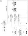
図1は、本発明に係る画像処理装置100の構成の一例を示す。画像処理装置100は、与えられた画像から、所望の画像を検出する。画像処理装置100は、テンプレート格納部10、モザイク画像生成部20、検出部60、履歴格納部70、及び選択部80を備える。
【0012】
テンプレート格納部10は、所望の画像要素の全体又は一部を示す複数のテンプレートを格納する。テンプレート格納部10は、所望の画像要素に基づいて生成された、所望の画像要素より解像度の低い複数のテンプレートを格納することが好ましい。例えば、テ
ンプレート格納部10は、所望の画像要素のモザイク画像を当該テンプレートとして格納する。本例において、テンプレート格納部10は、所望の画像要素の全体を示
す複数の第1テンプレートと、第1テンプレートの一部を示し、第1テンプレートより解像度の高い複数の第2テンプレートと、第2テンプレートの一部を示し、第2テンプレートより解像度の高い複数の第3テンプレートとを格納する。
【0013】
また、テンプレート格納部10は、それぞれの第2テンプレートを、いずれかの第1テンプレートに関連づけて格納する。また、テンプレート格納部10は、複数の第1テンプレートと対応付けられ、複数の第1テンプレートのいずれかの一部を示す第2テンプレートを格納する。例えば、テンプレート格納部10は、それぞれの第2テンプレートを、複数の第1テンプレートに関連づけて格納する。同様に、テンプレート格納部10は、それぞれの第3テンプレートを、いずれかの第2テンプレートに関連づけて格納する。テンプレート格納部10は、それぞれの第3テンプレートを、複数の第2テンプレートに関連づけて格納してよい。本例において、テンプレート格納部10は、複数の人物の顔を示す複数の第1テンプレートを格納し、目、鼻、口といった顔の構成要素を示す第2テンプレートを、いずれかの第1テンプレートと関連づけて格納し、目、鼻、口の細部を示す第3テンプレートを、いずれかの第2テンプレートと関連づけて格納する。
【0014】
モザイク画像生成部20は、与えられた画像に基づいて、当該与えられた画像より解像度の低い画像、すなわちモザイク画像を生成する。モザイク画像生成部20は、異なる解像度を有する複数のモザイク画像を生成してよい。例えば、モザイク画像生成部20は、第1テンプレートと解像度が略等しい第1モザイク画像と、第2テンプレートと解像度が略等しい第2モザイク画像と、第3テンプレートと解像度が略等しい第3モザイク画像とを生成してよい。また、モザイク画像生成部20は、当該与えられた画像の一部のモザイク画像を生成してよい。例えば、モザイク画像生成部20は、テンプレート格納部10が格納したテンプレートの画素数と、当該モザイク画像の画素数とが略等しくなるように、当該与えられた画像の一部を切り出し、モザイク画像を生成してよい。本例において、モザイク画像生成部20は、第1テンプレートと画素数が略等しい第1モザイク画像と、第2テンプレートと画素数が略等しい第2モザイク画像と、第3テンプレートと画素数が略等しい第3モザイク画像とを生成する。
【0015】
検出部60は、テンプレート格納部10が格納した複数のテンプレートのいずれかを用いて、当該与えられた画像から所望の画像要素を検出する。検出部60は、モザイク画像生成部20が生成したモザイク画像と、テンプレート格納部10が格納したテンプレートとを照合し、照合結果に基づいて当該与えられた画像から所望の画像要素を検出する。検出部60は、モザイク画像生成部20が生成したモザイク画像と、テンプレート格納部10が格納したテンプレートとを照合するための複数の照合手段を有する。例えば、検出部60は、テンプレートとモザイク画像との画素値間差分の総和に基づく方法、テンプレートとモザイク画像との画素値ベクトル間距離に基づく方法等により、テンプレートとモザイク画像とを照合してよい。また、検出部60は、固有空間法、カーネルベースメソッドといった手法により、テンプレートとモザイク画像とを照合してよい。
【0016】
履歴格納部70は、検出部60において用いられた、テンプレートの使用履歴を格納する。例えば、履歴格納部70は、複数のテンプレートのそれぞれに対して、検出部60が使用した回数を格納する。また、履歴格納部70は、予め定められた期間におけるテンプレートの使用履歴を格納してもよい。例えば、履歴格納部70は、予め定められた期間において、検出部60がいずれのテンプレートを何回使用したかを格納してよい。
【0017】
また、履歴格納部70は、複数のテンプレートのそれぞれが、検出部60において最後に使用された時間を格納してよい。また、履歴格納部70は、複数のテンプレートのそれぞれに対して、検出部60における検出結果を格納してよい。例えば、履歴格納部70は、それぞれのテンプレートが用いられた回数と、それぞれのテンプレートを用いて検出部60が所望の画像要素を検出した回数を格納してよい。検出部60は、履歴格納部70が格納したテンプレートの使用履歴に基づいて、テンプレート格納部10が格納した複数のテンプレートのいずれかを選択してよい。
【0018】
選択部80は、検出部60における複数の照合手段のいずれかを選択する。例えば、選択部80は、当該与えられた画像の画素数に基づいて、検出部60における複数の照合手段のいずれかを選択する。また、選択部80は、当該与えられた画像が、白黒画像であるかカラー画像であるかに基づいて、検出部60における複数の照合手段のいずれかを選択してもよい。
【0019】
検出部60は、第1比較部30−1、第2比較部30−2、第3比較部30−3、一致度算出部40、及び画像要素検出部50を有する。
【0020】
第1比較部30−1は、テンプレート格納部10が格納した複数のテンプレートのうちの第1テンプレートと、モザイク画像生成部20が生成した第1モザイク画像との一致度を算出する。第1比較部30−1は、第1テンプレートと第1モザイク画像との一致度を算出するための前述した複数の照合手段を有する。例えば、第1比較部30−1は、第1テンプレートと第1モザイク画像との画素値間差分の総和に基づく方法、第1テンプレートと第1モザイク画像との画素値ベクトル間距離に基づく方法等の照合手段により、第1テンプレートと第1モザイク画像との一致度を算出してよい。また、第1比較部30−1は、固有空間法、カーネルベースメソッドといった照合手段により、第1テンプレートと第1モザイク画像との一致度を算出してもよい。選択部80は、当該照合手段のいずれかを選択し、第1比較部30−1は選択された照合手段に基づいて、第1テンプレートと第1モザイク画像との一致度を算出する。
【0021】
第1比較部30−1は、所望の画像要素に対応する第1テンプレートと、第1モザイク画像との一致度を算出してよい。また、第1比較部30−1は、履歴格納部70が格納した複数の第1テンプレートの使用履歴に基づいて、使用する第1テンプレートを選択する。
【0022】
また、第1比較部30−1は、テンプレート格納部10が格納した複数の第1テンプレートの全ての第1テンプレートと、第1モザイク画像との一致度をそれぞれ算出してもよい。この場合、第1比較部30−1は、算出した一致度のうち、最も高い一致度を一致度算出部40に出力してよい。また、第1比較部30−1は、テンプレート格納部10が格納した複数の第1テンプレートのうち、ユーザが指定した1つ又は複数の第1テンプレートと、第1モザイク画像との一致度を算出してもよい。また、テンプレート格納部10は、複数の第1テンプレートを複数のグループに分類して格納し、第1比較部30−1は、ユーザが指定した1つ又は複数のグループの第1テンプレートと、第1モザイク画像との一致度をそれぞれ算出してもよい。この場合においても、第1比較部30−1は、算出した一致度のうち、最も高い一致度を一致度算出部40に出力してよい。
【0023】
第2比較部30−2は、第1テンプレートより解像度が高く、第1テンプレートの一部を示す第2テンプレートと、モザイク画像生成部20が生成した第1モザイク画像より解像度の高い第2モザイク画像との一致度を算出する。第2比較部30−2は、第1比較部30−1が用いた第1テンプレートに対応付けられた第2テンプレートと第2モザイク画像との一致度を算出する。また、第2比較部30−2は、第1比較部30−1が用いた第1テンプレートに対応付けられた第2テンプレートのうち、いずれかの第2テンプレートを選択し、選択した第2テンプレートと第2モザイク画像との一致度を算出する。また、第2比較部30−2は、複数の第2テンプレートを選択してよい。第2比較部30−2は、履歴格納部70が格納した第2テンプレートの使用履歴に基づいて、第2テンプレートを選択してよい。
【0024】
第2比較部30−2は、算出した全ての一致度を、一致度算出部40に出力してもよい。例えば、第2比較部30−2は、目、鼻、口のそれぞれを示す第2テンプレートと、第2モザイク画像との一致度をそれぞれ算出し、算出した全ての一致度を、一致度算出部40に出力してよい。
【0025】
また、第2比較部30−2は、第1比較部30−1が一致度算出部40に出力した一致度に対応する第1テンプレートに関連づけられた全ての第2テンプレートと、第2モザイク画像との一致度を算出してよい。この場合、第2比較部30−2は、第1比較部30−1と同様に、算出した一致度のうち、最も高い一致度を一致度算出部40に出力してよい。
【0026】
また、第2比較部30−2は、第1比較部30−1と同様に複数の照合手段を有する。第2比較部30−2は、選択部80が選択した照合手段を用いて、第2テンプレートと、第2モザイク画像との一致度を算出してよい。
【0027】
同様に、第3比較部30−3は、第2テンプレートより解像度が高く、第2テンプレートの一部又は全部を示す第3テンプレートと、モザイク画像生成部20が生成した第3モザイク画像との一致度を算出する。第3比較部30−3は、第2比較部30−2が一致度算出部40に出力した一致度に対応する第2テンプレートに関連づけられた第3テンプレートのうちから、用いる第3テンプレートを選択し、選択した第3テンプレートと、第3モザイク画像との一致度を算出してよい。また、第3比較部30−3は、第2比較部30−2が一致度算出部40に出力した一致度に対応する第2テンプレートに関連づけられた全ての第3テンプレートと、第3モザイク画像との一致度を算出してよい。また、第3比較部30−3は、履歴格納部70が格納した第3テンプレートの使用履歴に基づいて、用いる第3テンプレートを選択してよい。
【0028】
また、第3比較部30−3は、第1比較部30−1と同様に複数の照合手段を有する。第3比較部30−3は、選択部80が選択した照合手段を用いて、第3テンプレートと、第3モザイク画像との一致度を算出してよい。
【0029】
また、選択部80は、複数の比較部30に対して、それぞれ独立に照合手段を選択してよい。つまり、選択部80は、複数の比較部30において、異なる照合手段を選択してよく、同一の照合手段を選択してもよい。
【0030】
一致度算出部40は、受け取った全ての一致度に基づいて、所望の画像要素と与えられた画像との一致度を算出する。本例において、一致度算出部40は、第1比較部30−1、第2比較部30−2、及び第3比較部30−3がそれぞれ算出し、出力した一致度に基づいて、所望の画像要素と与えられた画像との一致度を算出する。
【0031】
画像要素検出部50は、一致度算出部40が算出した一致度に基づいて、与えられた画像から、所望の画像要素を検出する。画像要素検出部50は、一致度算出部40が算出した一致度が、予め定められた閾値より大きい場合、与えられた画像から、所望の画像要素を検出したと判断する。
【0032】
一致度算出部40は、比較部30−nが算出した一致度に重み付け係数を乗算する手段を有することが好ましい。本例において、一致度算出部40は、第1比較部30−1が算出した一致度に第1重み付け係数を乗算する手段と、第2比較部30−2が算出した一致度に第2重み付け係数を乗算する手段と、第3比較部30−3が算出した一致度に第3重み付け係数を乗算する手段とを有する。一致度算出部40は、当該重み付け係数を乗算した一致度の和に基づいて、所望の画像要素と与えられた画像との一致度を算出してよい。
【0033】
本例における画像処理装置100によれば、複数のテンプレートを上位のテンプレートのいずれかに対応付けているため、適切なテンプレートを効率よく選択することができる。また、本例における画像処理装置100によれば、複数の段階で算出した一致度の全てに基づいて所望の画像要素と与えられた画像との一致度を算出しているため、それぞれの段階における検出漏れを低減することができる。
【0034】
図2は、テンプレート格納部10が格納するテンプレートのデータ構成の一例を示す。テンプレート格納部10は、複数のテンプレートを格納する。テンプレート格納部10は、複数のテンプレートを複数の階層のデータ構成として格納する。本例において、テンプレート格納部10は、図2に示すように複数のテンプレートを3階層のデータ構成として格納する。また、本例において、テンプレート格納部10は、第1テンプレート12として人物の顔を示すテンプレートを格納し、第2テンプレート(14、16)として人物の目及び鼻を示すテンプレートを格納し、第3テンプレート(18、22、24)として、第2テンプレート(14、16)の一部を示すテンプレートを格納する。
【0035】
また、テンプレート格納部10は、上述したように下位のテンプレートをいずれかの上位のテンプレートに対応づけて格納する。本例において、第2テンプレート14bが、第1テンプレート12a及び第1テンプレート12bに対応付けられている。また、テンプレート格納部10は、上位のテンプレートを、複数の下位のテンプレートと対応づけて格納してよい。つまり、テンプレート格納部10は、複数の第2テンプレート14と対応する第1テンプレート12を少なくとも1つ格納してよい。本例において、第1テンプレート12aが、第2テンプレート14a及び第2テンプレート14bに対応付けられている。
【0036】
また、テンプレート格納部10は、テンプレートを同階層のテンプレートのいずれかに対応付けて格納してよい。本例において、テンプレート格納部10は、他の第2テンプレートと対応する第2テンプレートを少なくとも1つ格納する。例えば、テンプレート格納部10は、目を示す第2テンプレート14aを、鼻を示す第2テンプレート16のいずれかに対応付けて格納してよい。この場合、第2比較部30−2は、互いに対応付けられた複数の第2テンプレートと、第2モザイク画像との一致度をそれぞれ算出してよい。
【0037】
また、テンプレート格納部10は、互いに予め定められた関係を有する複数の第2テンプレートを格納してよい。本実施形態において、テンプレート格納部10は、第1テンプレート12中の、複数の第2テンプレート(14、16)のそれぞれが示す位置の相互関係を、当該関係として記憶する。第2比較部30−2は、当該関係に基づいて、第2テンプレートと第2モザイク画像との一致度を算出してよい。
【0038】
図3は、複数の比較部30−nの構成の一例を示す。それぞれの比較部30−nは、類似画像検出部30−n−a及び算出器30−n−bを有する。類似画像検出部30−1−aは、第1モザイク画像及び第1テンプレートを受け取り、第1モザイク画像から、第1テンプレートと類似する類似画像要素を検出する。算出器30−1−bは、類似画像検出部30−1−aが検出した類似画像要素と、第1テンプレートとの一致度を算出する。また、他の構成例においては、算出器30−1−bは、第1モザイク画像の複数の領域において、それぞれ第1テンプレートとの一致度を算出し、類似画像検出部30−1−aは、当該一致度が所定の閾値より大きい領域を、当該類似画像要素として検出してよい。比較部30−1は、当該類似画像要素と第1テンプレートとの一致度を、一致度算出部40に出力する。また、類似画像検出部30−1−aは、類似画像要素を検出した、第1モザイク画像における位置を、第2比較部30−2に出力する。
【0039】
第2比較部30−2は、第1比較部30−1と同一又は同様の機能及び構成を有する。類似画像検出部30−2−aは、第2モザイク画像及び第2テンプレートを受け取り、第2モザイク画像から、第2テンプレートと類似する類似画像要素を検出する。算出器30−2−bは、類似画像検出部30−2−aが検出した類似画像要素と、第2テンプレートとの一致度を算出する。類似画像検出部30−2−aは、第1類似画像検出部30−1−aが類似画像要素を検出した位置に基づいて、第2モザイク画像から類似画像要素を検出してよい。
【0040】
また、他の構成例においては、算出器30−2−bは、第2モザイク画像の複数の領域において、それぞれ第2テンプレートとの一致度を算出し、類似画像検出部30−2−aは、当該一致度が所定の閾値より大きい領域を、当該類似画像要素として検出してよい。比較部30−2は、当該類似画像要素と第2テンプレートとの一致度を、一致度算出部40に出力する。また、類似画像検出部30−2−aは、類似画像要素を検出した、第2モザイク画像における位置を、第3比較部30−3に出力する。
【0041】
第3比較部30−3は、第2比較部30−2と同一又は同様の機能及び構成を有する。類似画像検出部30−3−aは、第3モザイク画像及び第3テンプレートを受け取り、第3モザイク画像から、第3テンプレートと類似する類似画像要素を検出する。算出器30−3−bは、類似画像検出部30−3−aが検出した類似画像要素と、第3テンプレートとの一致度を算出する。類似画像検出部30−3−aは、第1類似画像検出部30−2−aが類似画像要素を検出した位置に基づいて、第3モザイク画像から類似画像要素を検出してよい。
【0042】
また、他の構成例においては、算出器30−3−bは、第3モザイク画像の複数の領域において、それぞれ第3テンプレートとの一致度を算出し、類似画像検出部30−3−aは、当該一致度が所定の閾値より大きい領域を、当該類似画像要素として検出してよい。比較部30−3は、当該類似画像要素と第3テンプレートとの一致度を、一致度算出部40に出力する。
【0043】
また、複数の比較部30−nは、受け取ったテンプレート又はモザイク画像を、回転、拡大、及び/又は縮小する手段を有してよい。複数の比較部30−nは、回転、拡大、及び/又は縮小したテンプレート又はモザイク画像に基づいて、一致度を算出してよい。
【0044】
図4は、画像処理装置100における一致度検出の動作について説明する。本例において、画像処理装置100は、所望の画像要素としての人物の顔と、与えられた画像との一致度を算出する。図4(a)に、モザイク画像生成部20に与えられた画像を示す。モザイク画像生成部20は、与えられた画像に基づいて第1モザイク画像を生成し、第1モザイク画像を図1に関連して説明した第1比較部30−1に供給する。モザイク画像生成部20は、テンプレート格納部10が格納した第1テンプレートと略同一の解像度の有する第1モザイク画像を生成することが望ましい。
【0045】
第1比較部30−1は、図3に関連して説明したように、第1テンプレートに基づいて、第1モザイク画像から人物の顔に類似する類似画像要素を検出する。本例において、第1比較部30−1は、図4(a)に示した箇所において、類似画像要素を検出する。図4(b)に、第1比較部30−1が検出した類似画像要素を示す。第1比較部30−1は、検出した類似画像要素に基づいて、第1モザイク画像と第1テンプレートとの一致度を算出する。本例において、第1比較部30−1は、第1モザイク画像と第1テンプレートとの一致度ρ1,1=0.98を算出する。但し、本例において一致度ρは、完全に一致した場合1の値を取り、全く一致しない場合に0の値を取る。
【0046】
図5は、図4において説明した一致度検出の動作の続きを説明する。モザイク画像生成部20は、与えられた画像に基づいて第2モザイク画像を生成し、第2モザイク画像を図1に関連して説明した第2比較部30−2に供給する。モザイク画像生成部20は、テンプレート格納部10が格納した第2テンプレートと略同一の解像度を有する第2モザイク画像を生成することが望ましい。モザイク画像生成部20は、与えられた画像において第1比較部30−1が類似画像要素を検出した位置に基づいて第2モザイク画像を生成してよい。つまり、モザイク画像生成部20は、与えられた画像に基づいて、第1モザイク画像の一部を示す第2モザイク画像を生成してよい。また、モザイク画像生成部20は、与えられた画像の全ての領域をモザイク化した第2モザイク画像を生成してもよい。
【0047】
第2比較部30−2は、図3に関連して説明したように、第2テンプレートに基づいて、第2モザイク画像から人物の顔の構成要素に類似する類似画像要素を検出する。第2比較部30−2は、複数の類似画像要素を検出してよい。本例において、第2比較部30−2は、類似画像要素として目と口を示す領域を、第2モザイク画像から検出する。図5(a)に、第2比較部30−2が検出した類似画像要素を示す。第2比較部30−2は、検出した類似画像要素に基づいて、第2モザイク画像と第2テンプレートとの一致度を算出する。本例において、第2比較部30−2は、第2モザイク画像と第2テンプレートとの一致度ρ2,1=0.85及びρ2,2=0.7を算出する。
【0048】
モザイク画像生成部20は、与えられた画像に基づいて第3モザイク画像を生成し、第3モザイク画像を図1に関連して説明した第3比較部30−3に供給する。モザイク画像生成部20は、テンプレート格納部10が格納した第3テンプレートと略同一の解像度を有する第3モザイク画像を生成するが望ましい。モザイク画像生成部20は、与えられた画像において第2比較部30−2が類似画像要素を検出した位置に基づいて第3モザイク画像を生成してよい。つまり、モザイク画像生成部20は、与えられた画像に基づいて、第2モザイク画像の一部を示す第3モザイク画像を生成してよい。また、モザイク画像生成部20は、与えられた画像の全ての領域をモザイク化した第3モザイク画像を生成してもよい。また、モザイク画像生成部20は、与えられた画像において第2モザイク画像と略同一の領域を示し、第2モザイク画像より解像度の高い第3モザイク画像を生成してよい。
【0049】
第3比較部30−3は、図3に関連して説明したように、第3テンプレートに基づいて、第3モザイク画像から人物の顔の構成要素に類似する類似画像要素を検出する。第3比較部30−3は、複数の類似画像要素を検出してよい。本例において、第3比較部30−3は、類似画像要素として目と口を示す領域を、第3モザイク画像から検出する。図5(b)に、第3比較部30−3が検出した類似画像要素を示す。第3比較部30−3は、検出した類似画像要素に基づいて、第3モザイク画像と第3テンプレートとの一致度を算出する。本例において、第3比較部30−3は、第3モザイク画像と第3テンプレートとの一致度ρ3,1=0.7及びρ3,2=0.6を算出する。
【0050】
図1から図3に関連して説明した画像処理装置100は、3つの比較部30を備えていたが、他の例においては、画像処理装置100は、更に多くの比較部30を備えてよい。例えば、画像処理装置100は、第4比較部を更に備えてよい。この場合、モザイク画像生成部20は、第3モザイク画像より解像度の高い第4モザイク画像を生成し、第4モザイク画像を第4算出部に供給する。図5(c)に第4モザイク画像の一例を示す。第4比較部は、第3比較部30−3と同様に、第4モザイク画像と第4テンプレートとの一致度を算出する。本例において、第4比較部は第4モザイク画像と第4テンプレートとの一致度ρ4,1=0.7及びρ4,2=0.6を算出する。
【0051】
複数の比較部は、前述したように一致度を算出するための複数の照合手段を有する。それぞれの比較部は、複数の照合手段のうち、いずれかの照合手段を用いて一致度を算出する。
【0052】
図1に関連して説明した一致度算出部40は、第1比較部30−1から第4算出部までが算出した全ての一致度に基づいて、所望の画像要素と与えられた画像との一致度を算出する。例えば、一致度算出部40は、下式に基づいて所望の画像要素と与えられた画像との一致度PSOFを算出する。
【数1】
【0053】
上式に示すように、下位の階層において算出した一致度ρに、上位の階層において算出した一致度ρを乗算することにより、特定の階層における一致度ρに基づく検出漏れを低減することができる。また、それぞれの重み付け係数に適当な値を与えることにより、上位の階層即ち、解像度の低い階層における一致度を重要視して所望の画像を検出するか、下位の階層即ち、解像度の高い階層における一致度を重要視して所望の画像を検出するかを選択してよい。画像処理装置100は、ユーザの指示に基づいて、重み付け係数の値を変更する手段を有することが好ましい。例えば、画像処理装置100は、ユーザが特定の人物の顔を検出したい場合に、下位の階層における重み付け係数の値を大きくしてよく、ユーザが不特定の人物の顔を検出したい場合に、上位の階層における重み付け係数の値を大きくしてよい。また、画像処理装置100は、比較部30が算出した全ての一致度に基づく、他の式によって所望の画像と与えられた画像との一致度を算出してよい。
【0054】
図1に関連して説明した画像要素検出部50は、一致度算出部40が算出した一致度PSOFに基づいて、与えられた画像から所望の画像要素を検出してよい。画像要素検出部50は、一致度PSOFが予め定められた閾値を越えた場合に、第1比較部30−1が検出した類似画像を、所望の画像要素として検出する。本例において説明した画像処理装置100によれば、比較部30が算出した全ての一致度に基づいて一致度PSOFを算出することにより、検出漏れ、誤検出を低減することができる。
【0055】
図6は、図3に関連して説明したテンプレート格納部10が格納するテンプレートの相互関係について説明する。本例において、テンプレート格納部10は、第1テンプレート12と関連づけて、第2テンプレート14、24及び26を格納する。本例において、テンプレート格納部10は、人物の顔を示す第1テンプレート12を格納する。また、テンプレート格納部10は、人物の右目、左目、鼻、及び口をそれぞれ示す第2テンプレート14a、14b、24、及び26を格納する。
【0056】
更には、テンプレート格納部10は、第1テンプレート中の、複数の第2テンプレートのそれぞれが示す位置の相互関係として、第1テンプレート12中の、第2テンプレート14aが示す右目の位置と、第2テンプレート14bが示す左目の位置との相互関係を格納する。テンプレート格納部10は、当該相互関係として、当該右目の位置から当該左目の位置へのX座標変位ΔX1、及びY座標変位ΔY1を格納する。
【0057】
同様に、テンプレート格納部10は、第2テンプレート14bと、第2テンプレート24との相互関係として、第1テンプレート12中の左目の位置から鼻の位置へのX座標変位ΔX2、及びY座標変位ΔY2を格納する。テンプレート格納部10は、第2テンプレート24と、第2テンプレート26との相互関係として、第1テンプレート12中の鼻の位置から口の位置へのX座標変位ΔX3、及びY座標変位ΔY3を格納する。テンプレート格納部10は、当該座標変位を、第1テンプレート12の左下隅を座標原点とし、右方をX座標方向、上方をY座標方向とする座標系において算出してよい。図1に関連して説明した画像処理装置100は、与えられた画像をモザイク化したモザイク画像と、上述したテンプレートを比較し、与えられた画像から所望の画像要素を検出する。また、本例においては、第2テンプレートとして右目、左目のテンプレートをそれぞれ格納したが、他の例においては、テンプレート格納部10は、図2において説明したように、両目を示すテンプレートを第2テンプレートとして格納してよいことは明らかである。また、テンプレート格納部10は、同様にそれぞれのテンプレートの相互関係を格納してよい。
【0058】
図7は、図3に関連して説明した類似画像検出部30−1−nにおける類似画像要素検出の動作の一例について説明する。類似画像検出部30−1−nは、与えられた画像から第1テンプレートに類似する第1類似画像要素、及び第2テンプレートに類似する第2類似画像要素を検出する。
【0059】
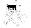
図7(a)は、所望の画像要素を検出するべき被処理画像である与えられた画像312を示す。与えられた画像312は、例えば検出対象物以外に背景を有する画像であってよい。
【0060】
図7(b)は、図1に関連して説明したモザイク画像生成部20が、与えられた画像312に基づいて生成する第1モザイク画像314と、図3に関連して説明した第1類似画像検出部30−1−aが第1モザイク画像中に検出した第1類似画像要素412とを示す。本実施形態において、第1類似画像検出部30−1−aは、第1モザイク画像314中に、図6に示した第1テンプレート12と類似する第1類似画像要素412を検出する。本実施形態において、第1モザイク画像314は、与えられた画像312の全体を示す。別の実施例において、第1モザイク画像314は、与えられた画像312の一部を示してもよい。
【0061】
図7(c)は、モザイク画像生成部20が、与えられた画像312に基づいて生成する第2モザイク画像316と、図3に関連して説明した第2類似画像検出部30−2−aが第2モザイク画像中に検出した第2類似画像要素422、424、426、及び428を示す。本実施形態において、第2類似画像検出部30−2−aは、第2モザイク画像316中に、図6に示した第2テンプレート14a、14b、24、及び26のそれぞれと類似する第2類似画像要素422、424、426、及び428を検出する。本実施形態において、第2モザイク画像316は、与えられた画像312の全体を示す。別の実施例において、第2モザイク画像316は、与えられた画像312の一部を示してもよい。
【0062】
本実施形態における画像処理装置100によれば、テンプレート格納部10が、第1テンプレート中の、複数の第2テンプレートのそれぞれが示す位置の相互関係を記憶することにより、少ない処理時間で類似画像要素を検出することができる。更には、本実施形態における画像処理装置100によれば、テンプレート格納部10が複数の第1テンプレート、及びそれぞれの第1テンプレートに関連づけられた第2テンプレートを格納することにより、第1類似画像要素の検出結果に従って適切な第2テンプレートを選択することができる。そのため、本実施形態における画像処理装置100によれば、多様な対象画像に対する類似画像要素の高精度、かつ高速な検出を行うことができる。
【0063】
また、複数の比較部30は、対応する類似画像検出部30−n−aが検出した類似画像要素の相互関係と、テンプレート格納部10が格納したテンプレートの相互関係との誤差に更に基づいて、前述した一致度を算出してよい。例えば、比較部30は、テンプレート格納部10が格納したテンプレートの相対位置と、対応する類似画像検出部30−n−aが検出した類似画像要素の相対位置との誤差に更に基づいて、一致度を算出してよい。また、テンプレート格納部10は、上位のテンプレートにおける、下位のテンプレートの位置を格納してよい。この場合、比較部30は、検出した類似画像要素の位置に更に基づいて、前述した一致度を算出してよい。以下、類似画像要素の位置に基づいて、一致度を算出する場合について説明する。
【0064】
図8は、類似画像要素の位置に基づいて、一致度を算出する場合について説明する。図3に関連して説明した第1類似画像要素検出部30−1−aは、与えられた画像312から、第1テンプレートと類似した第1類似画像要素412を検出する。第1類似画像要素検出部30−1−aは、検出した第1類似画像要素412の、与えられた画像における位置情報を第2類似画像要素検出部30−2−a及び算出器30−1−bに供給する。
【0065】
第2類似画像要素検出部30−2−aは、受け取った位置情報に基づいて、与えられた画像312から、第2テンプレートと類似した第2類似画像要素(422、424、426、428)を検出する。第2類似画像要素検出部30−2−aは、類似画像要素50の範囲内において、第2類似画像要素(422、424、426、428)を検出してよい。また、第2類似画像要素検出部30−2−aは、テンプレート格納部10が格納した基準位置周辺から、第2類似画像要素(422、424、426、428)を検出してよい。
【0066】
本例において、第2類似画像要素検出部30−2−aは、図8に示すように右目、左目、鼻、口を示す画像要素を、第2類似画像要素(422、424、426、428)として検出する。第2類似画像要素検出部30−2−aは、検出した第2類似画像要素(422、424、426、428)の与えられた画像における位置情報を、算出器30−2−bに供給する。
【0067】
算出器30−n−bは、類似画像要素検出部30−n−aが検出した類似画像要素の位置情報に基づいて、前述した一致度を算出する。例えば、算出器30−n−bは、類似画像要素検出部30−n−aが検出した類似画像要素の位置情報と、テンプレート格納部10が格納した基準位置との距離に基づいて、類似画像要素を所望の画像要素として検出するか否かを判定してよい。また、算出器30−n−aは、類似画像要素検出部30−n−aが検出した複数の類似画像要素の、与えられた画像におけるそれぞれの相対位置に更に基づいて、一致度を算出してよい。以上説明した画像処理装置100によれば、誤検出を更に低減し、精度よく所望の画像要素を検出することができる。
【0068】
また前述したように、複数の比較部30は、与えられた画像と所望の画像要素とを照合する複数の照合手段をそれぞれ有する。複数の比較部30は複数の照合手段のいずれかに基づいて、与えられた画像と所望の画像要素との一致度を算出する。選択部80は、当該与えられた画像に関する情報に基づいて、複数の比較部30における複数の照合手段のいずれかを選択する。複数の比較部30は、それぞれ選択された照合手段に基づいて、与えられた画像と所望の画像要素との一致度を算出する。
【0069】
選択部80は、当該与えられた画像の画素数に基づいて、比較部30における複数の照合手段のいずれかを選択してよい。また、選択部80は、当該与えられた画像が、白黒画像であるかカラー画像であるかに基づいて、比較部30における複数の照合手段のいずれかを選択してよい。また、選択部80は、複数の比較部30に対して、それぞれ独立に照合手段を選択してよい。つまり、選択部80は、複数の比較部30において、異なる照合手段を選択してよく、同一の照合手段を選択してもよい。
【0070】
また、画像処理装置100が、撮像装置により撮像された画像を当該与えられた画像として受け取った場合、選択部80は、当該画像が撮像された撮像条件に基づいて、複数の照合手段のいずれかを選択してよい。例えば、選択部80は、当該画像が撮像された日時、場所、ストロボの有無、光学及び電子ズーム倍率等に基づいて、複数の照合手段のいずれかを選択してよい。
【0071】
また、画像処理装置100が、exif形式のディジタル画像データを当該与えられた画像として受け取った場合、選択部80は、当該ディジタル画像データのAPP1データに基づいて、複数の照合手段のいずれかを選択してよい。例えば、選択部80は、APP1データのうち、当該画像が撮像された日時、場所、ストロボの有無、光学及び電子ズーム倍率、当該画像の画素数、当該画像が白黒画像であるかカラー画像であるか等を示すデータに基づいて、複数の照合手段のいずれかを選択してよい。
【0072】
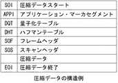
図9は、exif形式のディジタル画像データのデータ構造の一例を示す。exif形式のディジタル画像データは、図9に示すように、SOIデータ、APP1データ、DQTデータ、DHTデータ、SOFデータ、SOSデータ、圧縮データデータ、及びEOIデータを有する。SOIデータは圧縮データの開始を示し、APP1データは、アプリケーション・マーカセグメントを示し、DQTデータは、量子化テーブルを示し、DHTデータはハフマンテーブルを示し、SOFデータは、フレームヘッダを示し、SOSデータはスキャンヘッダを示し、圧縮データデータは画像データを示し、EOIデータは圧縮データの終了を示す。
【0073】
画像処理装置100がexif形式のディジタル画像データを受け取った場合、選択部80は、図9に示したAPP1データに基づいて複数の照合手段のいずれかを選択してよい。APP1データは、画像データの付属情報を示すアプリケーション・マーカセグメントを示す。選択部80は、APP1データのうち、当該画像が撮像された日時、場所、ストロボの有無、光学及び電子ズーム倍率、当該画像の画素数、当該画像が白黒画像であるかカラー画像であるか等を示すデータに基づいて、複数の照合手段のいずれかを選択する。
【0074】
本例における画像処理装置100によれば、複数の段階に対してそれぞれ適切な照合手段を選択することができる。また、本例における画像処理装置100によれば、与えられた画像に対してそれぞれ適切な照合手段を選択することができる。また、本例における画像処理装置100によれば、照合に用いるテンプレート毎に、照合手段を選択することができる。このため、画像処理装置100によれば、与えられた画像から所望の画像要素を精度よく且つ効率よく検出することができる。また、図1から図9に関連して説明した画像処理装置100は、例えば上述した画像処理を行うためのプログラムを格納したコンピュータであってよい。
【0075】
図10は、画像処理装置100としてのコンピュータ200の構成の一例を示す。コンピュータ200は、CPU700と、ROM702と、RAM704と、通信インターフェース706と、ハードディスクドライブ710と、FDディスクドライブ712と、CD−ROMドライブ716とを備える。CPU700は、ROM702、RAM704、ハードディスク710、FDディスク714、及びCD−ROM718に格納されたプログラムに基づいて動作する。通信インターフェース706は、インターネット等を介して外部と通信する。格納装置の一例としてのハードディスクドライブ710は、設定情報及びCPU700が動作するプログラムを格納する。ROM702、RAM704、及び/又はハードディスクドライブ710は、コンピュータ200を図1から図9に関連して説明した画像処理装置100として機能させるための画像処理プログラムを格納する。
【0076】
フロッピーディスクドライブ712はフロッピーディスク714からデータまたはプログラムを読み取りCPU700に提供する。CD−ROMドライブ716はCD−ROM718からデータまたはプログラムを読み取りCPU700に提供する。通信インターフェース706は、インターネット10に接続してデータを送受信する。
【0077】
CPU700が実行するソフトウエアは、フロッピーディスク714またはCD−ROM718等の記録媒体に格納されて利用者に提供される。記録媒体に格納されたソフトウエアは圧縮されていても非圧縮であっても良い。ソフトウエアは記録媒体からハードディスクドライブ710にインストールされ、RAM704に読み出されてCPU700により実行される。
【0078】
当該画像処理プログラムは、コンピュータ200を、図1から図9に関連して説明したテンプレート格納部10、モザイク画像生成部20、比較部30、一致度算出部40、画像要素検出部50、検出部60、履歴格納部70、及び選択部80として機能させてよい。つまり、本例においてテンプレート格納部10及び履歴格納部70はRAM704、又はハードディスクドライブ710であってよい。また、テンプレート格納部10及び履歴格納部70は、FDディスクが挿入されたFDドライブであってよく、CD−ROM718が挿入されたCD−ROMドライブ716であってもよい。また、モザイク画像生成部20、比較部30、一致度算出部40、画像要素検出部50、検出部60、及び選択部80は、CPU700であってよい。また、コンピュータ200は、モザイク画像生成部20、比較部30、一致度算出部40、画像要素検出部50、検出部60、及び選択部80の機能を行う他の演算装置を更に備えてよい。
【0079】
コンピュータ200は、所望の画像を検出するべき被検出画像を、CD−ROM718、及び/又はFDディスク716から受け取ってよい。また、通信インターフェースを介して、外部から被検出画像を受け取ってもよい。また、コンピュータ200は、ディジタルカメラにおいて画像を格納する記憶素子から、被検出画像を読み込む手段を有してよい。
【0080】
また、画像処理プログラムは記録媒体から直接RAMに読み出されて実行されても、一旦ハードディスクドライブにインストールされた後にRAMに読み出されて実行されても良い。更に、上記プログラムは単一の記録媒体に格納されても複数の記録媒体に格納されても良い。また記録媒体に格納される画像処理プログラムは、オペレーティングシステムとの共同によってそれぞれの機能を提供してもよい。例えば、画像処理プログラムは、機能の一部または全部を行うことをオペレーティングシステムに依頼し、オペレーティングシステムからの応答に基づいて機能を提供するものであってもよい。
【0081】
画像処理プログラムを格納する記録媒体としては、フロッピーディスク、CD−ROMの他にも、DVD、PD等の光学記録媒体、MD等の光磁気記録媒体、テープ媒体、磁気記録媒体、ICカードやミニチュアーカードなどの半導体メモリー等を用いることができる。又、専用通信ネットワークやインターネットに接続されたサーバシステムに設けたハードディスクまたはRAM等の格納装置を記録媒体として使用してもよい。本例におけるコンピュータ200によれば、画像処理装置100と同様に、誤検出を低減し、精度よく所望の画像要素を検出することができる。
【0082】
以上、本発明を実施の形態を用いて説明したが、本発明の技術的範囲は上記実施形態に記載の範囲には限定されない。上記実施形態に、多様な変更または改良を加えることができる。そのような変更または改良を加えた形態も本発明の技術的範囲に含まれ得ることが、特許請求の範囲の記載から明らかである。
【0083】
【発明の効果】
上記説明から明らかなように、本発明によれば、与えられた画像から所望の画像を精度よく検出することができる。
【図面の簡単な説明】
【図1】 本発明に係る画像処理装置100の構成の一例を示す図である。
【図2】 テンプレート格納部10が格納するテンプレートのデータ構成の一例を示す図である。
【図3】 複数の比較部30−nの構成の一例を示す示す図である。
【図4】 画像処理装置100における一致度検出の動作について説明する図である。
【図5】 図4において説明した一致度検出の動作の続きを説明する図である。
【図6】 図3に関連して説明したテンプレート格納部10が格納するテンプレートの相互関係を説明する図である。
【図7】 図3に関連して説明した類似画像検出部30−1−nにおける類似画像要素検出の動作の一例について説明する図である。
【図8】 類似画像要素の位置に基づいて、一致度を算出する場合について説明する図である。
【図9】 exif形式のディジタル画像データのデータ構造の一例を示す図である。
【図10】 画像処理装置100としてのコンピュータ200の構成の一例を示す図である。
【符号の説明】
10・・・テンプレート格納部、12・・・第1テンプレート、(14、16)・・・第2テンプレート、(18、22、24)・・・第3テンプレート、20・・・モザイク画像生成部、30・・・比較部、30−n−a・・・類似画像検出部、30−n−b・・・算出器、40・・・一致度算出部、50・・・画像要素検出部、(52、54、56、58、62)・・・類似画像要素、60・・・検出部、70・・・履歴格納部、80・・・選択部、100・・・画像処理装置、200・・・コンピュータ、312・・・与えられた画像、314・・・第1モザイク画像、412・・・第1類似画像要素、(422、424、426、428)・・・第2類似画像要素、700・・・CPU、702・・・ROM、704・・・RAM、706・・・通信インターフェース、710・・・ハードディスクドライブ、712・・・フロッピーディスクドライブ、714・・・フロッピーディスク、716・・・CD−ROMドライブ、718・・・CD−ROM[0001]
BACKGROUND OF THE INVENTION
The present invention relates to an image processing apparatus. In particular, the present invention relates to an image processing apparatus that detects a desired image element from a given image.
[0002]
[Prior art]
Conventionally, there is an image recognition apparatus disclosed in Japanese Patent Laid-Open No. 5-174149 as an image recognition apparatus for specifying a recognition target image. This image recognition device roughly mosaics an object image to be recognized, uses this as a feature of the target image at the time of search, scans an unknown image, finds an approximate position and size, and then recognizes This is a device that finely mosaics the object image to be used and scans the vicinity of the rough position already obtained to find the recognition target image.
[0003]
In a conventional image recognition apparatus, the number of pixels of a mosaic image used as a feature of a target image is sequentially changed in three stages, and the distance between each mosaic image and an unknown image is calculated. The image recognition apparatus detects a recognition target image based on the calculated distance.
[0004]
[Problems to be solved by the invention]
However, in the conventional image recognition apparatus, a plurality of templates for finding a recognition target image are stored, each template is compared with the target image, and the recognition target image is detected. For this reason, the conventional image recognition apparatus takes time for collation.
[0005]
SUMMARY An advantage of some aspects of the invention is that it provides an image processing apparatus, an image processing method, and a program that can solve the above-described problems. This object is achieved by a combination of features described in the independent claims. The dependent claims define further advantageous specific examples of the present invention.
[0006]
[Means for Solving the Problems]
That is, in the first aspect of the present invention, an image processing apparatus detects a desired image element from a given image, and includes a plurality of first templates indicating the desired image element and a plurality of first templates. A template storage unit that stores a second template indicating a part of any of the plurality of first templates, and selects one of the plurality of first templates, and the selected first template and the Compare with given imageTo calculate the degree of coincidence The first comparison unit compares the given image with the second template corresponding to the first template selected by the first comparison unit.To calculate the degree of coincidence In the second comparison unit, the first comparison unit and the second comparison unitThe degree of coincidence between the given image and the desired image element obtained by multiplying the calculation results of the degree of coincidence by the first and second weighting coefficients and using the sum of them. A detection unit that detects the desired image element from the given image, and a history storage unit that stores a use history of the template used in the detection unit, the detection unit storing the history An image processing apparatus is provided that detects one of a plurality of templates stored in the template storage unit based on a use history of the template stored in the unit.
[0007]
template The storage unit preferably stores at least one first template corresponding to the plurality of second templates. Also,template The storage unit preferably stores at least one second template corresponding to another second template.
[0008]
The second comparison unit may compare a plurality of second templates corresponding to the first template selected by the first comparison unit with the given image. Also,template The storage unit may store a second template having a higher resolution than the first template.
[0009]
The above summary of the invention does not enumerate all necessary features of the present invention, and sub-combinations of these feature groups can also be the invention.
[0010]
DETAILED DESCRIPTION OF THE INVENTION
Hereinafter, the present invention will be described through embodiments of the invention. However, the following embodiments do not limit the claimed invention, and all combinations of features described in the embodiments are solutions of the invention. It is not always essential to the means.
[0011]
FIG. 1 shows an example of the configuration of an
[0012]
The
The
The plurality of first templates and a part of the first template are shown, and the resolution is higher than that of the first template.high A plurality of second templates and a part of the second template are shown, and the resolution is higher than that of the second template.high A plurality of third templates are stored.
[0013]
The
[0014]
The mosaic
[0015]
The detection unit 60 detects a desired image element from the given image using any of the plurality of templates stored in the
[0016]
The
[0017]
Further, the
[0018]
The
[0019]
The detection unit 60 includes a first comparison unit 30-1, a second comparison unit 30-2, a third comparison unit 30-3, a coincidence
[0020]
The first comparison unit 30-1 calculates the degree of coincidence between the first template among the plurality of templates stored in the
[0021]
The first comparison unit 30-1 may calculate the degree of coincidence between the first template corresponding to the desired image element and the first mosaic image. The first comparison unit 30-1 selects the first template to be used based on the usage histories of the plurality of first templates stored in the
[0022]
In addition, the first comparison unit 30-1 may calculate the degree of coincidence between all the first templates of the plurality of first templates stored in the
[0023]
The second comparison unit 30-2 has a higher resolution than the first template, a second template indicating a part of the first template, and a second mosaic image having a higher resolution than the first mosaic image generated by the mosaic
[0024]
The second comparison unit 30-2 may output all the calculated degrees of coincidence to the degree of
[0025]
Further, the second comparison unit 30-2 includes all the second templates associated with the first template corresponding to the degree of coincidence output from the first comparison unit 30-1 to the coincidence
[0026]
Moreover, the 2nd comparison part 30-2 has several collation means similarly to the 1st comparison part 30-1. The second comparison unit 30-2 may calculate the degree of coincidence between the second template and the second mosaic image using the matching unit selected by the
[0027]
Similarly, the third comparison unit 30-3 has a higher resolution than the second template, and the third template indicating a part or all of the second template matches the third mosaic image generated by the mosaic
[0028]
Moreover, the 3rd comparison part 30-3 has several collation means similarly to the 1st comparison part 30-1. The third comparison unit 30-3 may calculate the degree of coincidence between the third template and the third mosaic image using the matching unit selected by the
[0029]
In addition, the
[0030]
The
[0031]
The image
[0032]
The
[0033]
According to the
[0034]
FIG. 2 shows an example of the data structure of the template stored in the
[0035]
Further, the
[0036]
Further, the
[0037]
Further, the
[0038]
FIG. 3 shows an example of the configuration of the plurality of comparison units 30-n. Each comparison unit 30-n includes a similar image detection unit 30-na and a calculator 30-n-b. The similar image detection unit 30-1-a receives the first mosaic image and the first template, and detects a similar image element similar to the first template from the first mosaic image. The calculator 30-1-b calculates the degree of coincidence between the similar image element detected by the similar image detection unit 30-1-a and the first template. In another configuration example, the calculator 30-1-b calculates the degree of coincidence with the first template in each of the plurality of regions of the first mosaic image, and the similar image detection unit 30-1-a A region where the degree of coincidence is larger than a predetermined threshold value may be detected as the similar image element. The comparison unit 30-1 outputs the degree of coincidence between the similar image element and the first template to the degree of
[0039]
The second comparison unit 30-2 has the same or similar function and configuration as the first comparison unit 30-1. The similar image detection unit 30-2-a receives the second mosaic image and the second template, and detects a similar image element similar to the second template from the second mosaic image. The calculator 30-2-b calculates the degree of coincidence between the similar image element detected by the similar image detection unit 30-2-a and the second template. The similar image detection unit 30-2-a may detect the similar image element from the second mosaic image based on the position where the first similar image detection unit 30-1-a detects the similar image element.
[0040]
In another configuration example, the calculator 30-2-b calculates the degree of coincidence with the second template in each of the plurality of regions of the second mosaic image, and the similar image detection unit 30-2-a A region where the degree of coincidence is larger than a predetermined threshold value may be detected as the similar image element. The comparison unit 30-2 outputs the degree of coincidence between the similar image element and the second template to the degree of
[0041]
The third comparison unit 30-3 has the same or similar function and configuration as the second comparison unit 30-2. The similar image detection unit 30-3-a receives the third mosaic image and the third template, and detects a similar image element similar to the third template from the third mosaic image. The calculator 30-3-b calculates the degree of coincidence between the similar image element detected by the similar image detection unit 30-3-a and the third template. The similar image detection unit 30-3-a may detect the similar image element from the third mosaic image based on the position where the first similar image detection unit 30-2-a detects the similar image element.
[0042]
In another configuration example, the calculator 30-3-b calculates the degree of coincidence with the third template in each of the plurality of regions of the third mosaic image, and the similar image detection unit 30-3-a A region where the degree of coincidence is larger than a predetermined threshold value may be detected as the similar image element. The comparison unit 30-3 outputs the degree of coincidence between the similar image element and the third template to the degree of
[0043]
The plurality of comparison units 30-n may include means for rotating, enlarging, and / or reducing the received template or mosaic image. The plurality of comparison units 30-n may calculate the degree of coincidence based on the rotated or enlarged and / or reduced template or mosaic image.
[0044]
FIG. 4 illustrates the coincidence detection operation in the
[0045]
As described with reference to FIG. 3, the first comparison unit 30-1 detects a similar image element similar to a human face from the first mosaic image based on the first template. In this example, the first comparison unit 30-1 detects similar image elements at the locations illustrated in FIG. FIG. 4B shows similar image elements detected by the first comparison unit 30-1. The first comparison unit 30-1 calculates the degree of coincidence between the first mosaic image and the first template based on the detected similar image element. In this example, the first comparison unit 30-1 determines the degree of coincidence ρ between the first mosaic image and the first template.1,1 = 0.98 is calculated. However, in this example, the degree of coincidence ρ takes a value of 1 when it is completely coincident, and takes a value of 0 when it is not coincident at all.
[0046]
FIG. 5 explains the continuation of the coincidence degree detection operation described in FIG. The mosaic
[0047]
As described with reference to FIG. 3, the second comparison unit 30-2 detects similar image elements similar to the constituent elements of the human face from the second mosaic image based on the second template. The second comparison unit 30-2 may detect a plurality of similar image elements. In this example, the 2nd comparison part 30-2 detects the area | region which shows eyes and a mouth as a similar image element from a 2nd mosaic image. FIG. 5A shows similar image elements detected by the second comparison unit 30-2. The second comparison unit 30-2 calculates the degree of coincidence between the second mosaic image and the second template based on the detected similar image element. In this example, the second comparison unit 30-2 determines the degree of coincidence ρ between the second mosaic image and the second template.2,1 = 0.85 and ρ2, 2 = 0.7 is calculated.
[0048]
The mosaic
[0049]
As described with reference to FIG. 3, the third comparison unit 30-3 detects similar image elements similar to the constituent elements of the human face from the third mosaic image based on the third template. The third comparison unit 30-3 may detect a plurality of similar image elements. In this example, the 3rd comparison part 30-3 detects the area | region which shows eyes and a mouth as a similar image element from a 3rd mosaic image. FIG. 5B shows similar image elements detected by the third comparison unit 30-3. The third comparison unit 30-3 calculates the degree of coincidence between the third mosaic image and the third template based on the detected similar image element. In this example, the third comparison unit 30-3 determines the degree of coincidence ρ between the third mosaic image and the third template.3,1 = 0.7 and ρ3, 2 = 0.6 is calculated.
[0050]
The
[0051]
The plurality of comparison units have a plurality of collating means for calculating the degree of coincidence as described above. Each comparison unit calculates the degree of coincidence using any one of the plurality of matching means.
[0052]
The coincidence
[Expression 1]
[0053]
As shown in the above equation, by multiplying the coincidence degree ρ calculated in the lower hierarchy by the coincidence degree ρ calculated in the upper hierarchy, it is possible to reduce detection omission based on the coincidence degree ρ in a specific hierarchy. . In addition, by assigning appropriate values to the respective weighting factors, a desired image is detected with an emphasis on the degree of matching in the upper hierarchy, that is, the lower resolution hierarchy, or in the lower hierarchy, that is, the higher resolution hierarchy. You may select whether to detect a desired image with importance on the degree of coincidence. The
[0054]
The image
[0055]
FIG. 6 illustrates the interrelationship between templates stored in the
[0056]
Furthermore, the
[0057]
Similarly, the
[0058]
FIG. 7 illustrates an example of a similar image element detection operation in the similar image detection unit 30-1-n described with reference to FIG. The similar image detection unit 30-1-n detects a first similar image element similar to the first template and a second similar image element similar to the second template from the given image.
[0059]
FIG. 7A shows a given
[0060]
FIG. 7B illustrates the first
[0061]
FIG. 7C illustrates the second
[0062]
According to the
[0063]
Further, the plurality of comparison units 30 are further based on an error between the mutual relationship between the similar image elements detected by the corresponding similar image detection unit 30-na and the mutual relationship between the templates stored in the
[0064]
FIG. 8 illustrates a case where the degree of coincidence is calculated based on the position of similar image elements. The first similar image element detection unit 30-1-a described with reference to FIG. 3 detects the first
[0065]
Based on the received position information, the second similar image element detection unit 30-2-a extracts second similar image elements (422, 424, 426, 428) similar to the second template from the given
[0066]
In this example, the second similar image element detection unit 30-2-a converts the image elements indicating the right eye, the left eye, the nose, and the mouth into the second similar image elements (422, 424, 426, 428, as shown in FIG. ) To detect. The second similar image element detection unit 30-2-a supplies the position information in the given image of the detected second similar image element (422, 424, 426, 428) to the calculator 30-2-b. .
[0067]
The calculator 30-n-b calculates the degree of coincidence described above based on the position information of the similar image element detected by the similar image element detection unit 30-na. For example, the calculator 30-n-b calculates the similar image based on the distance between the position information of the similar image element detected by the similar image element detection unit 30-na and the reference position stored by the
[0068]
Further, as described above, the plurality of comparison units 30 each have a plurality of collating units that collate a given image with a desired image element. The plurality of comparison units 30 calculate the degree of coincidence between a given image and a desired image element based on any one of the plurality of collating means. The
[0069]
The
[0070]
In addition, when the
[0071]
In addition, when the
[0072]
FIG. 9 shows an example of the data structure of the digital image data in the exif format. As shown in FIG. 9, the digital image data in the exif format has SOI data, APP1 data, DQT data, DHT data, SOF data, SOS data, compressed data data, and EOI data. SOI data indicates the start of compressed data, APP1 data indicates an application marker segment, DQT data indicates a quantization table, DHT data indicates a Huffman table, SOF data indicates a frame header, and SOS data Indicates a scan header, compressed data data indicates image data, and EOI data indicates the end of the compressed data.
[0073]
When the
[0074]
According to the
[0075]
FIG. 10 shows an example of the configuration of a
[0076]
The
[0077]
Software executed by the
[0078]
The image processing program executes the
[0079]
The
[0080]
Further, the image processing program may be directly read from the recording medium into the RAM and executed, or once installed in the hard disk drive, may be read into the RAM and executed. Further, the program may be stored in a single recording medium or a plurality of recording media. The image processing program stored in the recording medium may provide each function in cooperation with the operating system. For example, the image processing program may request the operating system to perform part or all of the function and provide the function based on a response from the operating system.
[0081]
In addition to floppy disks and CD-ROMs, recording media for storing image processing programs include optical recording media such as DVDs and PDs, magneto-optical recording media such as MDs, tape media, magnetic recording media, IC cards and miniatures. A semiconductor memory such as an arc card can be used. A storage device such as a hard disk or a RAM provided in a server system connected to a dedicated communication network or the Internet may be used as a recording medium. According to the
[0082]
As mentioned above, although this invention was demonstrated using embodiment, the technical scope of this invention is not limited to the range as described in the said embodiment. Various modifications or improvements can be added to the above embodiment. It is apparent from the scope of the claims that the embodiments added with such changes or improvements can be included in the technical scope of the present invention.
[0083]
【The invention's effect】
As is apparent from the above description, according to the present invention, a desired image can be accurately detected from a given image.
[Brief description of the drawings]
FIG. 1 is a diagram illustrating an example of a configuration of an
FIG. 2 is a diagram illustrating an example of a data configuration of a template stored in a
FIG. 3 is a diagram illustrating an example of a configuration of a plurality of comparison units 30-n.
FIG. 4 is a diagram for explaining an operation of coincidence detection in the image processing apparatus.
FIG. 5 is a diagram for explaining the continuation of the coincidence degree detection operation described in FIG. 4;
6 is a diagram for explaining the interrelationship between templates stored in the
7 is a diagram for explaining an example of a similar image element detection operation in the similar image detection unit 30-1-n described with reference to FIG. 3; FIG.
FIG. 8 is a diagram for explaining a case where the degree of coincidence is calculated based on the position of a similar image element.
FIG. 9 is a diagram illustrating an example of a data structure of digital image data in an exif format.
FIG. 10 is a diagram illustrating an example of a configuration of a
[Explanation of symbols]
DESCRIPTION OF
Claims (5)
Translated fromJapanese前記所望の画像要素を示す複数の第1テンプレートと、前記複数の第1テンプレートと対応付けられ、前記複数の第1テンプレートのいずれかの一部を示す第2テンプレートとを格納するテンプレート格納部と、
前記複数の第1テンプレートのいずれかを選択し、選択した前記第1テンプレートと前記与えられた画像とを比較してその一致度を算出する第1比較部と、
前記第1比較部において選択された第1テンプレートに対応する第2テンプレートと前記与えられた画像とを比較してその一致度を算出する第2比較部と、
前記第1比較部及び前記第2比較部におけるそれぞれの一致度の算出結果に対して第1及び第2の重み付け係数を乗算してそれらの和を用いることによって得られる前記与えられた画像と前記所望の画像要素との一致度に基づいて、前記与えられた画像から前記所望の画像要素を検出する検出部と、
前記第1比較部及び前記第2比較部においてそれぞれ使用された前記第1テンプレート及び前記第2テンプレートの使用履歴を格納する履歴格納部と
を備え、
前記第1比較部及び前記第2比較部は、それぞれ、前記履歴格納部が格納した前記第1テンプレート及び前記第2テンプレートの使用履歴に基づいて、前記テンプレート格納部が格納した複数の前記第1テンプレート及び前記第2テンプレートのいずれかを選択することを特徴とする画像処理装置。An image processing apparatus for detecting a desired image element from a given image,
A template storage unit that stores a plurality of first templates indicating the desired image elements, and a second template associated with the plurality of first templates and indicating a part of the plurality of first templates; ,
A first comparison unit that selects one of the plurality of first templates, compares the selected first template with the given image, and calculates a degree of coincidence thereof;
A second comparison unit that compares a second template corresponding to the first template selected in the first comparison unit and the given image to calculate the degree of coincidence;
The given image obtained by multiplying the calculation results of the respective matching degrees in the first comparison unit and the second comparison unit by the first and second weighting coefficients and using the sum thereof, and the A detection unit that detects the desired image element from the given image based on the degree of coincidence with the desired image element;
A history storage unit that stores usage histories ofthe first template and the second template used inthe first comparison unit and the second comparison unit ,respectively .
The first comparison unit and the second comparison unit mayeach include aplurality of the first templates stored in the template storage unit based on usage histories ofthe first template and the second template stored in the history storage unit. An image processing apparatus thatselects either atemplate orthe second template .
Priority Applications (2)
| Application Number | Priority Date | Filing Date | Title |
|---|---|---|---|
| JP2002006809AJP4226247B2 (en) | 2002-01-15 | 2002-01-15 | Image processing device |
| US10/322,711US7319778B2 (en) | 2002-01-15 | 2002-12-19 | Image processing apparatus |
Applications Claiming Priority (1)
| Application Number | Priority Date | Filing Date | Title |
|---|---|---|---|
| JP2002006809AJP4226247B2 (en) | 2002-01-15 | 2002-01-15 | Image processing device |
Publications (2)
| Publication Number | Publication Date |
|---|---|
| JP2003208617A JP2003208617A (en) | 2003-07-25 |
| JP4226247B2true JP4226247B2 (en) | 2009-02-18 |
Family
ID=19191274
Family Applications (1)
| Application Number | Title | Priority Date | Filing Date |
|---|---|---|---|
| JP2002006809AExpired - Fee RelatedJP4226247B2 (en) | 2002-01-15 | 2002-01-15 | Image processing device |
Country Status (2)
| Country | Link |
|---|---|
| US (1) | US7319778B2 (en) |
| JP (1) | JP4226247B2 (en) |
Families Citing this family (15)
| Publication number | Priority date | Publication date | Assignee | Title |
|---|---|---|---|---|
| RU2160467C1 (en)* | 1999-07-08 | 2000-12-10 | Яхно Владимир Григорьевич | Method for adaptive recognition of information images and device which implements said method |
| US7120279B2 (en)* | 2003-01-30 | 2006-10-10 | Eastman Kodak Company | Method for face orientation determination in digital color images |
| JP4198071B2 (en)* | 2004-01-20 | 2008-12-17 | オリンパス株式会社 | Information presentation system |
| US7643702B1 (en)* | 2004-07-23 | 2010-01-05 | Adobe Systems Incorporated | Object detection in images using a graphics processor |
| DE602005012672D1 (en)* | 2005-02-21 | 2009-03-26 | Mitsubishi Electric Corp | Method for detecting facial features |
| US20080104011A1 (en)* | 2005-06-30 | 2008-05-01 | Takao Shibasaki | Retrieval System and Retrieval Method |
| KR20070118156A (en)* | 2005-06-30 | 2007-12-13 | 올림푸스 가부시키가이샤 | Search system and search method |
| JP4845755B2 (en)* | 2007-01-30 | 2011-12-28 | キヤノン株式会社 | Image processing apparatus, image processing method, program, and storage medium |
| JP2009003730A (en)* | 2007-06-22 | 2009-01-08 | Nintendo Co Ltd | Information processing program and information processor |
| WO2010055638A1 (en)* | 2008-11-13 | 2010-05-20 | パナソニック株式会社 | Video data creation device, video data creation method, video data creation program, recording medium thereof, and integrated circuit |
| TWI435261B (en)* | 2010-08-17 | 2014-04-21 | Wistron Corp | Electronic device and method for implementing icon board based operation interface thereof |
| JP5706647B2 (en)* | 2010-09-03 | 2015-04-22 | キヤノン株式会社 | Information processing apparatus and processing method thereof |
| GB2484969B (en)* | 2010-10-29 | 2013-11-20 | Canon Kk | Improved reference frame for video encoding and decoding |
| US8651615B2 (en) | 2011-12-19 | 2014-02-18 | Xerox Corporation | System and method for analysis of test pattern image data in an inkjet printer using a template |
| KR101726692B1 (en)* | 2012-08-24 | 2017-04-14 | 한화테크윈 주식회사 | Apparatus and method for extracting object |
Family Cites Families (10)
| Publication number | Priority date | Publication date | Assignee | Title |
|---|---|---|---|---|
| GB2177834B (en)* | 1985-07-02 | 1988-11-16 | Ferranti Plc | Pattern detection in two dimensional signals |
| JP3041056B2 (en) | 1990-01-10 | 2000-05-15 | 株式会社東芝 | Semiconductor pellet detection method |
| JPH04148384A (en) | 1990-10-11 | 1992-05-21 | Mitsubishi Electric Corp | Dictionary matching method |
| JP2849256B2 (en) | 1991-12-26 | 1999-01-20 | 日本電信電話株式会社 | Image recognition device |
| JPH07302327A (en) | 1993-08-11 | 1995-11-14 | Nippon Telegr & Teleph Corp <Ntt> | Object image detection method and detection apparatus |
| JPH10222678A (en) | 1997-02-05 | 1998-08-21 | Toshiba Corp | Object detection device and object detection method |
| US6295374B1 (en)* | 1998-04-06 | 2001-09-25 | Integral Vision, Inc. | Method and system for detecting a flaw in a sample image |
| US6594629B1 (en)* | 1999-08-06 | 2003-07-15 | International Business Machines Corporation | Methods and apparatus for audio-visual speech detection and recognition |
| US6678414B1 (en)* | 2000-02-17 | 2004-01-13 | Xerox Corporation | Loose-gray-scale template matching |
| US6964023B2 (en)* | 2001-02-05 | 2005-11-08 | International Business Machines Corporation | System and method for multi-modal focus detection, referential ambiguity resolution and mood classification using multi-modal input |
- 2002
- 2002-01-15JPJP2002006809Apatent/JP4226247B2/ennot_activeExpired - Fee Related
- 2002-12-19USUS10/322,711patent/US7319778B2/ennot_activeExpired - Lifetime
Also Published As
| Publication number | Publication date |
|---|---|
| US7319778B2 (en) | 2008-01-15 |
| US20030133613A1 (en) | 2003-07-17 |
| JP2003208617A (en) | 2003-07-25 |
Similar Documents
| Publication | Publication Date | Title |
|---|---|---|
| JP4226247B2 (en) | Image processing device | |
| JP5121506B2 (en) | Image processing apparatus, image processing method, program, and storage medium | |
| JP5629803B2 (en) | Image processing apparatus, imaging apparatus, and image processing method | |
| US8526742B2 (en) | Image processing apparatus, method, and program that classifies data of images | |
| KR100480781B1 (en) | Method of extracting teeth area from teeth image and personal identification method and apparatus using teeth image | |
| JP4743823B2 (en) | Image processing apparatus, imaging apparatus, and image processing method | |
| JP5668932B2 (en) | Image identification device, image identification method, image identification program, and recording medium | |
| JP2000105829A (en) | Face part detection method and apparatus | |
| JP2003132358A (en) | Image processing method, apparatus and system | |
| JP4303191B2 (en) | Image recognition system, image recognition method, and image recognition program | |
| JP2011134114A (en) | Pattern recognition method and pattern recognition apparatus | |
| JP2009048347A (en) | Image processing apparatus, image processing method, and image processing program | |
| KR20130120175A (en) | Apparatus, method and computer readable recording medium for generating a caricature automatically | |
| JPH10301948A (en) | Image and video search method | |
| JP5441151B2 (en) | Facial image tracking device, facial image tracking method, and program | |
| JPH11161791A (en) | Individual identification device | |
| JP2005318546A (en) | Image recognition system, image recognition method, and image recognition program | |
| US7602943B2 (en) | Image processing apparatus, image processing method, and image processing program | |
| JP2002207963A (en) | Image processing device | |
| JP2012221053A (en) | Image recognition apparatus, image recognition method and program | |
| JP2000090191A (en) | Device and method for face recognition | |
| JP2003208611A (en) | Image processing device, method therefor, and program | |
| JP2001331804A (en) | Image region detecting apparatus and method | |
| JP2019008480A (en) | Image analysis program, image analysis apparatus, and image analysis method | |
| JPH11213156A (en) | Image processing apparatus and method, recording medium |
Legal Events
| Date | Code | Title | Description |
|---|---|---|---|
| A621 | Written request for application examination | Free format text:JAPANESE INTERMEDIATE CODE: A621 Effective date:20040304 | |
| A977 | Report on retrieval | Free format text:JAPANESE INTERMEDIATE CODE: A971007 Effective date:20060928 | |
| A131 | Notification of reasons for refusal | Free format text:JAPANESE INTERMEDIATE CODE: A131 Effective date:20061003 | |
| A521 | Request for written amendment filed | Free format text:JAPANESE INTERMEDIATE CODE: A523 Effective date:20061204 | |
| A711 | Notification of change in applicant | Free format text:JAPANESE INTERMEDIATE CODE: A712 Effective date:20061207 | |
| A02 | Decision of refusal | Free format text:JAPANESE INTERMEDIATE CODE: A02 Effective date:20070123 | |
| A521 | Request for written amendment filed | Free format text:JAPANESE INTERMEDIATE CODE: A523 Effective date:20070222 | |
| A911 | Transfer to examiner for re-examination before appeal (zenchi) | Free format text:JAPANESE INTERMEDIATE CODE: A911 Effective date:20070404 | |
| A912 | Re-examination (zenchi) completed and case transferred to appeal board | Free format text:JAPANESE INTERMEDIATE CODE: A912 Effective date:20070427 | |
| A521 | Request for written amendment filed | Free format text:JAPANESE INTERMEDIATE CODE: A523 Effective date:20081023 | |
| A01 | Written decision to grant a patent or to grant a registration (utility model) | Free format text:JAPANESE INTERMEDIATE CODE: A01 | |
| A61 | First payment of annual fees (during grant procedure) | Free format text:JAPANESE INTERMEDIATE CODE: A61 Effective date:20081126 | |
| FPAY | Renewal fee payment (event date is renewal date of database) | Free format text:PAYMENT UNTIL: 20111205 Year of fee payment:3 | |
| R150 | Certificate of patent or registration of utility model | Ref document number:4226247 Country of ref document:JP Free format text:JAPANESE INTERMEDIATE CODE: R150 Free format text:JAPANESE INTERMEDIATE CODE: R150 | |
| FPAY | Renewal fee payment (event date is renewal date of database) | Free format text:PAYMENT UNTIL: 20111205 Year of fee payment:3 | |
| FPAY | Renewal fee payment (event date is renewal date of database) | Free format text:PAYMENT UNTIL: 20121205 Year of fee payment:4 | |
| R250 | Receipt of annual fees | Free format text:JAPANESE INTERMEDIATE CODE: R250 | |
| FPAY | Renewal fee payment (event date is renewal date of database) | Free format text:PAYMENT UNTIL: 20121205 Year of fee payment:4 | |
| FPAY | Renewal fee payment (event date is renewal date of database) | Free format text:PAYMENT UNTIL: 20131205 Year of fee payment:5 | |
| R250 | Receipt of annual fees | Free format text:JAPANESE INTERMEDIATE CODE: R250 | |
| R250 | Receipt of annual fees | Free format text:JAPANESE INTERMEDIATE CODE: R250 | |
| R250 | Receipt of annual fees | Free format text:JAPANESE INTERMEDIATE CODE: R250 | |
| R250 | Receipt of annual fees | Free format text:JAPANESE INTERMEDIATE CODE: R250 | |
| R250 | Receipt of annual fees | Free format text:JAPANESE INTERMEDIATE CODE: R250 | |
| R250 | Receipt of annual fees | Free format text:JAPANESE INTERMEDIATE CODE: R250 | |
| R250 | Receipt of annual fees | Free format text:JAPANESE INTERMEDIATE CODE: R250 | |
| R250 | Receipt of annual fees | Free format text:JAPANESE INTERMEDIATE CODE: R250 | |
| R250 | Receipt of annual fees | Free format text:JAPANESE INTERMEDIATE CODE: R250 | |
| LAPS | Cancellation because of no payment of annual fees |