JP4225849B2 - Guided map display method and apparatus for navigation system - Google Patents
Guided map display method and apparatus for navigation systemDownload PDFInfo
- Publication number
- JP4225849B2 JP4225849B2JP2003192752AJP2003192752AJP4225849B2JP 4225849 B2JP4225849 B2JP 4225849B2JP 2003192752 AJP2003192752 AJP 2003192752AJP 2003192752 AJP2003192752 AJP 2003192752AJP 4225849 B2JP4225849 B2JP 4225849B2
- Authority
- JP
- Japan
- Prior art keywords
- turning
- display
- point
- display condition
- navigation system
- Prior art date
- Legal status (The legal status is an assumption and is not a legal conclusion. Google has not performed a legal analysis and makes no representation as to the accuracy of the status listed.)
- Expired - Fee Related
Links
- 238000000034methodMethods0.000titleclaimsdescription23
- 230000008859changeEffects0.000claimsdescription31
- 238000010586diagramMethods0.000description20
- 230000006870functionEffects0.000description9
- 230000000694effectsEffects0.000description6
- 230000008569processEffects0.000description4
- 238000010187selection methodMethods0.000description4
- 238000013459approachMethods0.000description3
- 238000012545processingMethods0.000description3
- 238000004891communicationMethods0.000description2
- 238000012217deletionMethods0.000description2
- 230000037430deletionEffects0.000description2
- 238000001698laser desorption ionisationMethods0.000description2
- 238000012986modificationMethods0.000description2
- 230000004048modificationEffects0.000description2
- 230000002194synthesizing effectEffects0.000description2
- 238000007796conventional methodMethods0.000description1
- 238000013500data storageMethods0.000description1
- 238000001514detection methodMethods0.000description1
- 238000005516engineering processMethods0.000description1
- 238000005259measurementMethods0.000description1
- 238000002360preparation methodMethods0.000description1
- 230000009467reductionEffects0.000description1
Images


Classifications
- G—PHYSICS
- G08—SIGNALLING
- G08G—TRAFFIC CONTROL SYSTEMS
- G08G1/00—Traffic control systems for road vehicles
- G08G1/09—Arrangements for giving variable traffic instructions
- G08G1/0962—Arrangements for giving variable traffic instructions having an indicator mounted inside the vehicle, e.g. giving voice messages
- G08G1/0968—Systems involving transmission of navigation instructions to the vehicle
- G08G1/0969—Systems involving transmission of navigation instructions to the vehicle having a display in the form of a map
- G—PHYSICS
- G01—MEASURING; TESTING
- G01C—MEASURING DISTANCES, LEVELS OR BEARINGS; SURVEYING; NAVIGATION; GYROSCOPIC INSTRUMENTS; PHOTOGRAMMETRY OR VIDEOGRAMMETRY
- G01C21/00—Navigation; Navigational instruments not provided for in groups G01C1/00 - G01C19/00
- G01C21/26—Navigation; Navigational instruments not provided for in groups G01C1/00 - G01C19/00 specially adapted for navigation in a road network
- G01C21/34—Route searching; Route guidance
- G01C21/36—Input/output arrangements for on-board computers
- G01C21/3626—Details of the output of route guidance instructions
- G01C21/3632—Guidance using simplified or iconic instructions, e.g. using arrows
Landscapes
- Engineering & Computer Science (AREA)
- Radar, Positioning & Navigation (AREA)
- Remote Sensing (AREA)
- Physics & Mathematics (AREA)
- General Physics & Mathematics (AREA)
- Automation & Control Theory (AREA)
- Navigation (AREA)
- Instructional Devices (AREA)
- Traffic Control Systems (AREA)
Description
Translated fromJapanese【0001】
【発明の属する技術分野】
本発明は、ナビゲーションシステムの誘導地図表示方法及び装置に関し、さらに詳しくは、目的地への経路において、近づきつつある曲がり角と、その後に続く曲がり角を適当な数だけ示す誘導地図を適当な表示寸法で表示することができるナビゲーションシステムの誘導地図表示方法及び装置に関するものである。
【0002】
【従来の技術】
車両用ナビゲーションシステムは、運転者が選択した目的地へ容易に運転して到達できるようにするために車両の走行を誘導する。一般的に、ナビゲーションシステムは、誘導地図上において、経路を強調表示して次の曲がり角の方向を表示する。本発明は、目的地への経路において、短い区間に連続的に二つ以上の曲がり角がある場合に曲がり角の方向を表示するための表示方法及び装置に関するものである。
【0003】
まず、ナビゲーションシステムの基本技術について簡単に説明する。このようなナビゲーションシステムは、車両の位置を検出し、例えばCD−ROM(読み取り専用コンパクトディスク)やDVD(デジタル多目的ディスク)などのようなデータ保存媒体から、車両の現在の位置における領域を含む地図データを読み出し、地図の画像をモニタスクリーン(画面)上に表示するとともに、車両の現在の位置を地図画像上に表示するマーク(車両マーク)を重ねる。
【0004】
車両の位置は、車両に搭載した内蔵式ナビゲーションセンサ(例えば、走行距離センサや方位センサ)、もしくは人工衛星(衛星誘導システム)を含むGPS(Global Positioning System)によって決定する。人工衛星は絶対位置検出が可能であると共に内蔵式ナビゲーションセンサより位置検出精度が高い。しかし、衛星誘導システムは、トンネルやビルの中などのような、衛星無線信号が妨害される場所においては位置を検出できないという問題を有していた。従って、最近のナビゲーションシステムは、内蔵式ナビゲーションと衛星誘導システムとの両方を利用して性能を高めている。
【0005】
車両の現在位置は、車両の走行と共に変化するので、画面上の地図画像中の車両マークはそれに応じて移動する。あるいは、車両マークを、例えば画像の中心など、ある所定の位置に固定して地図をスクロールする。いずれの方法においても、ナビゲーションシステムにより運転者は車両位置周辺の地図情報を一目で認識できる。
【0006】
目的地を設定しないと、ナビゲーションシステムは、地図画像上に車両の現在位置を示す位置表示地図として機能する。目的地を設定すると、ナビゲーションシステムは、出発点から目的地までの誘導経路を設定する経路誘導機能を開始する。一般的に経路誘導機能は、誘導経路を地図上に表示しながらモニタ画面に拡大した交差点の図と車両が走行すべき方向を表示する交差点誘導過程を実行する。目的地を入力すると、ナビゲーションシステムのCPUが現在の車両位置から目的地までの最も適した誘導経路を決定し、メモリに誘導経路を構成するノード(緯度と経度で表示する)を連続して保存する。
【0007】
実際の走行中、メモリに保存した一連のノードから誘導経路のうち、モニタ画面の地図表示領域に表示する部分を検索して、誘導経路のその部分を強調表示し、他の経路から区別できるようにする。車両が近づいている交差点から所定の距離の範囲内に入ると、交差点誘導図(車両が交差点で曲がる方向を示す矢印を表示した拡大もしくは強調表示した交差点の図)を表示して、交差点で選択可能な道路または方向のうち望ましいものを運転者に知らせる。
【0008】
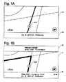
図1Aは、車両の現在位置を示すマーク(車両マーク)VCPを地図画像21上に含む位置表示地図画面の例を示す。一般的に、ナビゲーションシステムは、地図画像21内に車両が走行している道路を示すと共に、“W.190TH ST.,(西190番街)”のような道路の名前をモニタ画面上の情報ボックス23に表示する。北方向表示マークNP、地図の縮尺、及び現在の時刻などのような他の情報も表示画面に表示される。このように、位置表示地図画面は、地図画像上の車両の現在位置を表すが、ナビゲーションシステムに目的地を設定していないため、経路誘導機能は果たさない。
【0009】
図1Bは、経路誘導機能を実行する経路誘導表示の例を示す。経路誘導表示は、目的地を指定した後に起動する。図1Aに示す位置表示地図に類似した地図画像21に加え、この例では、画面の上の誘導情報ボックス22内に、交差点で車両が曲がる方向(左)を示す矢印を表示する。誘導情報ボックス22は、現在走行している道路“W.190TH ST”と交差する道路の名前“プレイリー通り”と、交差点までの距離も表示する。よって、ナビゲーションシステムは、車両が“プレイリー通り”との交差点を左に曲がらなければならないことを表示する。
【0010】
一般的に、現在走行中の通り“W.190TH ST”と“プレイリー通り”の左側が、地図画像21の中で強調表示される。さらに、このような経路誘導には、音声指示も伴う。次の交差点での走行方向が左であるならば、ナビゲーションシステムは、“次の交差点で左に曲がってください”などのような音声ガイダンスを行う。この例では、表示画面の下の情報ボックス24には、最終目的地までの残りの距離や最終目的地到着の予定時間に関する情報が表示される。
【0011】
図1Bに示すような経路誘導モードで誘導させるには、システムが目的地に到着するまでの経路を1つ以上見つけることができるようにナビゲーションシステムに目的地を指定しなければならない。図2A〜2Fは、目的地を入力する作業中にモニタ画面に表示される表示画面の例を示したものである。
【0012】
メニューキーを操作することにより、図2Aに示すようなメインメニュー25がナビゲーションシステムに表示されるので、メニューアイテム“目的地”をメインメニューから選択する。これにより、ナビゲーションシステムが図2Bに示すような“目的地選択方法入力”メニュー27を表示するので、目的地を選択するための入力方法を指定する。“目的地選択方法入力”メニュー27は、▲1▼目的地の市と住所を指定する“住所(Address)”、▲2▼互いに交差する市街地における二本の道路の名前を指定する“交差点(Intersection)”、及び名前、カテゴリー、または電話番号に基づいてプログラム化された目的地を選択する“ポイントオブインタレスト(Point of Interest)”を含む、目的地を選択するための各種方法を表示する。
【0013】
“目的地選択方法入力”メニュー27の他の方法は、▲4▼ナビゲーションシステムに保存してある最近の目的地に基づいて指定する“最近の経路(Recent Route)”、▲5▼システムに保存された住所から目的地の住所を選択する“アドレスブック(Address Book)”、及び▲6▼地図上の目的地にカーソルを合わせることによって目的地を指定する“マップカーソル(Map Cursor)”を含む。例えば、アドレスブック内の情報は、運転者が頻繁に訪れる場所の名前と住所のリストから構成する。
【0014】
例えば、図2Bに示す“ポイントオブインタレスト”を選択すると、ナビゲーションシステムは、図2Cに示すような“カテゴリーリスト”メニュー28を表示する。“カテゴリーリスト”メニュー28には、“銀行”、“レストラン”、“ホテル”、“ショッピング”、その他のような異なる各種のカテゴリーが含まれる。例えば“ショッピング”のカテゴリーを選択したとすると、ナビゲーションシステムは、図3A及び図3Bに示すような“名前リスト”を表示する。“名前リスト”は、例えば、車両からの距離によって分類した店やショッピングモールの名前のリストを示す。画面上の住所情報ボックス31には、リスト33の中の強調表示された名前の住所と電話番号が表示される。住所情報ボックス31は、強調表示した店への距離も表示することができる。一般的にナビゲーションシステムは、所定距離範囲内の店の名前を数十から数百保存してあり、表示画面の1ページ毎にいくつかの店を表示する。使用者は、表示画面をスクロールすれば、図3Bに示すような名前リスト36の中から他の店の名前を見ることができる。
【0015】
ナビゲーションシステムに目的地が保存されていなかった場合、使用者は例えば、図2Bに示す“目的地選択方法入力”メニュー27の中から“住所(Address)”または“交差点(Intersection)”を選択することによって目的地を入力することができる。続いてナビゲーションシステムは、図3Fに示すような、モニタ画面に表示されるキーボード(キーパッド)38によって住所入力ボックス37に市と住所を入力する“道路名入力”画面を表示する。
【0016】
目的地を入力した後、ナビゲーションシステムは、例えば、目的地へ到達する最短の経路、一般道より高速道路を優先使用する経路、または有料道路を通らない経路などに基づいて目的地までの経路を決定する。よって、ナビゲーションシステムは、図1Bに示すような、経路誘導を行う経路誘導表示に移る。
【0017】
経路誘導において、矢印(矢印誘導)か、もしくは、図1Bに示すような強調表示経路(地図誘導)によって次に曲がる方向を示す。このナビゲーションシステムによる経路誘導は、音声指示によっても行われる。第1の曲がり角の比較的近くに第2の曲がり角がある場合、ナビゲーションシステムは、第1と第2の曲がり角を予め決めた条件によって表示画面に表示する。
【0018】
このような、第1の曲がり角または第1と第2の両方の曲がり角を表示する例を図4A〜4B及び図5A〜5Bに示す(特許文献1)。
図4A及び4Bは、第1の曲がり角P1と第2の曲がり角P2との間の距離D1が所定の距離より短い場合を示している。これとは対照的に図4A及び4Bは、第1の曲がり角Q1と第2の曲がり角Q2との間の距離D2が所定の距離より長い場合を示している。
【0019】
図4Aの場合のように、第2の曲がり角が第1の曲がり角の近くにある時は、ナビゲーションシステムは、第1の曲がり角P1と第2の曲がり角P2との間の距離D1が所定の距離より短いことを検出する。そして、ナビゲーションシステムは、図4Bに示すように、それぞれ第1の曲がり角P1と第2の曲がり角P2の方向を示す二つの矢印を画面上に部分的に重なった状態で示す。
【0020】
図5Aの場合のように、第2の曲がり角が第1の曲がり角から離れている時は、ナビゲーションシステムは、第1の曲がり角P1と第2の曲がり角P2との間の距離D2が所定の距離より長いことを検出する。そして、ナビゲーションシステムは図5Bに示すように第1の曲がり角P1のみの方向を表す矢印を一つだけ表示する。
【特許文献1】
米国特許第5,739,772号
【0021】
【発明が解決しようとする課題】
この従来の技術では、一つもしくは二つの矢印しか画面上に表示されない。よって、運転者に、次の曲がり角がいつやってくるか、また、その次の曲がり角のすぐ後にもう一度曲がらなければならないかなど、その後に続く曲がり角に関する十分な情報もしくは経路の画像を提供することができない。このため、最適な寸法の誘導地図の中に最適な数の曲がり角を示すことにより、運転者が近づいてくる曲がり角及びその後の曲がり角が一目でわかるようにする機能がナビゲーションシステムに要望される。
【0022】
従って、本発明の目的は、使用者が、最適なウィンドウ寸法の地図誘導モードにおいて方向転換通過点と方向とを容易かつ迅速に把握することができるナビゲーションシステムの表示方法と装置を提供することにある。
【0024】
【課題を解決するための手段】
本発明の方法は、誘導経路途中の方向転換通過点と、その方向転換通過点における転換方向を表示することによって、使用者を目的地まで誘導するナビゲーションシステムの誘導地図表示方法であり、誘導経路上の方向転換通過点であって少なくとも二つの所定の表示条件を満足する連続する複数の方向転換通過点を検出するステップ、前記検出した複数の方向転換通過点を含む誘導地図を拡大してディスプレイ画面に表示するステップを有している。上記二つの表示条件は、以下の第1表示条件と、第2表示条件〜第6表示条件のうち少なくとも1つの表示条件である。
【0026】
方向転換通過点Pn+1を表示するための第1の表示条件は、二つの隣接する方向転換通過点Pn及びPn+1の間の道路に沿った走行距離をL(n,n+1)、二つの隣接する方向転換通過点間の道路の最大許容走行距離をLmaxとした場合、L(n,n+1)≦Lmaxが成り立つことである。
【0027】
方向転換通過点Pn+1を表示するための第2の表示条件は、二つの隣接する方向転換通過点PnとPn+1の間の道路に沿った走行距離をL(n,n+1)、第1、第2の方向転換通過点P1,P2間の直線距離をD(1,2)、表示を許容する二つの方向転換通過点間の最大許容直線距離を決定するための相対係数をKDとした場合、L(n,n+1)≦KDD(1,2)が成り立つことである。この第2の表示条件は、二つの方向転換通過点間の走行距離L(n,n+1)の代わりに点PnとPn+1との間の直線距離D(n,n+1)を使用し、表示を許容する二つの方向転換通過点間の最大許容直線距離を決定するための相対係数をKDDとすれば、D(n,n+1)≦KDDD(1,2)と変形することができる。
【0028】
方向転換通過点Pn+1を表示するための第3の表示条件は、二つの隣接する方向転換通過点PnとPn+1の間の道路に沿った走行距離をL(n,n+1)、二つの隣接する方向転換通過点PnとPn+1の間の直線距離をD(n,n+1)、直線距離に対する最大走行距離を決定する相対係数をKLDとした場合、L(n,n+1)≦KLDD(n,n+1)が成り立つことである。
【0029】
方向転換通過点Pn+1を表示するための第4の表示条件は、自車位置に最も近い第1の方向転換通過点P1とn番目の方向転換通過点Pn+1との間の直線距離をD(1,n+1)、第1の方向転換通過点P1とn番目の方向転換通過点Pn+1との間の最大許容直線距離をDmaxとした場合、D(1,n+1)≦Dmaxが成り立つことである。さらに、第5の表示条件は、連続する方向転換通過点数をmとし、同時に誘導地図に表示することができる最大許容方向転換通過点数をMmaxとした場合、m≦Mmaxが成り立つことである。
【0030】
本発明のもう一つの態様は、車両用ナビゲーションシステムの表示装置である。この表示装置は、目的地までの経路における一連の曲がり角に各種表示条件を適用し、方向転換通過点の数を調整して拡大誘導地図を作成する、上記の表示方法を実現するための各種の手段によって構成されている。
【0031】
本発明によると、車両用ナビゲーションシステムにより、使用者は、目的地への経路における連続した曲がり角とその方向を容易に把握することができる。運転者は、一目で方向転換通過点をチェックして把握することができ、走行車線の変更など次の方向転換のために十分に準備することができる。よって、運転者は、目的地まで快適に、そして自信を持って走行することができる。
【0032】
【発明の実施の形態】
本発明のナビゲーションシステムについて、添付の図面を参照しながら詳しく説明する。本発明のナビゲーションシステムは、使用者が交差点と方向転換の方向を迅速かつ容易に把握できる最適な寸法の誘導地図で最適な数の曲がり角(方向転換通過点)を表示するように設計した。本発明の操作過程と表示画面の例を図8〜13に示しており、各種条件を使って該当する道路の地理とレイアウトに対して最適な表示方法を決定する。図14および図15は本発明のナビゲーションシステムの操作の流れを示す。
【0033】
目的地までの経路において所定距離の範囲内に2箇所以上の曲がり角(方向転換通過点)がある場合、ナビゲーションシステムは単純化した地図画像とその方向転換の方向を表示して運転者を誘導する。本発明によると、ナビゲーションシステムは、各種条件を方向転換通過点に適用して、地図誘導画面上に同時に表示する方向転換通過点の数を調整する。条件の適用順が重要ではないことは、留意する点である。ナビゲーションシステムは、調整した数の方向転換通過点の方向を示す強調表示した経路を含む拡大地図画像を表示する。
【0034】
条件と図8〜13の表示例の詳細に入る前に、図6を参照しながら本発明のナビゲーションシステムの基本的構造について、そして、図7A及び7Bを参照しながら、ナビゲーションシステムのリモートコントローラの例について簡単に説明する。
【0035】
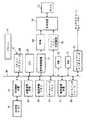
図6のブロック図において、ナビゲーションシステムは、地図情報を保存するためのCD−ROM、DVD、ハードディスク、または他の保存手段(以下DVDと呼ぶ)である地図保存媒体41と、DVDから地図情報を読み取るための操作を制御するDVD制御装置42と、車両の現在位置を測定するための位置測定装置43を備えている。位置測定装置43は、移動距離を検出するための車両速度センサと、移動方向を検出するためのジャイロスコープと、位置を算出するためのマイクロプロセッサと、GPSレシーバなどを備える。
【0036】
図6のブロック図には、さらに、DVD41から読み出した地図情報を保存するための地図情報メモリ44と、DVD41から読み出したポイントオブインタレスト(POI)情報のようなデータベース情報を保存するためのデータベースメモリ45と、メニュー選択操作、拡大/縮小操作、目的地入力操作などを行うためのリモートコントローラ47と、リモートコントローラインターフェース48とが含まれる。
【0037】
リモートコントローラ47は、図7Aに示すような各種機能キーと、図7Bに示すような数字キーを有する。数字キーは、図7Aの下側部分の蓋を開けると現れる。リモートコントローラ47は、ジョイスティック/入力キー47aと、ロータリーエンコーダ47bと、取り消しキー47cと、MP/RGキー47dと、メニューキー47eと、ズーム/スクロールキー47qと、モニタON/OFFキー47fと、リモートコントロール送信機47gと、プランキー47hと、N/Hキー47iと、ボイスキー47jと、リストキー47kと、迂回キー47lと、目的地削除キー47mと、削除キー47nと、数字キー47oと、OKキー47pとを有する。
【0038】
ジョイティック/入力キー47aは、メニューの中の強調表示されたアイテムを選択し、地図表示と車両位置アイコンを移動する。ロータリーエンコーダ47bは、ズーム倍率を変更し、リストページをスクロールし、カーソルを移動させたりするときなどに使用する。取り消しキー47cは、現在表示されている画面を取り消したり、あるいは、画面を前のメニュー画面に戻すときに使用する。MP/RGキー47dは、誘導中に詳細地図誘導表示と基本誘導表示(矢印誘導表示)との間を切り替える。メニューキー47eは、メインメニューを表示する。プランキー47hは、本日のプラン機能による経路設定へのガイダンスを開始する。N/Hキー47iは、北を上に表示する表示方法と向かっている方向を上に表示する表示方法との間を切り替える。そして、ボイスキー47jは、音声による指示を開始する。
【0039】
上記のようなリモートコントローラがメニューの選択、選択した機能の実行などの典型的な例ではあるが、ナビゲーションシステムは、リモートコントローラを介して行うのと同じ、そして類似した操作を行うことができる他のさまざまな入力方法も有する。例えば、ナビゲーションシステムは、ダッシュボード上に取り付けたシステムのヘッドユニット上に設けたハードキーとジョイスティック、タッチスクリーン、及び音声通信などを含んでいてもよい。
【0040】
図6を再び参照すると、ナビゲーションシステムは、さらに、システム内の上記の機器をつなぐバス46と、ナビゲーションシステムの操作全体を制御するためのプロセッサ(CPU)49と、ナビゲーション制御に必要なルート検索プログラムやマップマッチングプログラムなどのような各種制御プログラムを保存するためのROM50と、誘導経路などのような処理結果を保存するためのRAM51と、音声による指示で交差点における走行方向を誘導するための音声誘導装置52と、地図情報に基づいて地図画像(地図誘導画像及び矢印誘導画像)を生成する表示制御装置53と、表示制御装置によって生成された画像を保存するVRAM54と、メニュー画像/各種リスト画像を生成するためのメニュー/リスト生成装置55と、VRAM54及びメニュー/リスト生成装置55からの画像を合成するための合成装置56と、モニタ(表示装置)57と、使用者とシステムの間の音声通信用のボイスインターフェース58と、システムのパネル上のハードキー及びジョイスティック、または、システムのタッチスクリーンなどのような他の各種の入力手段をつなぐキー−スクリーンインターフェース59などを備える。
【0041】
図8〜13を参照すると、本発明において、ナビゲーションシステムは、各種表示条件を適用して、表示すべき方向転換箇所(方向転換通過点)の数を決定し、全ての方向転換通過点が含まれるように縮尺を制御して誘導地図を拡大表示する。例えば市街地を運転しているときには、目的地までの経路における比較的小さい領域内で車両が何回も方向展開をしなければならないような状況も起こりうる。ナビゲーションシステムがこのすべての方向転換を誘導地図に表示しようとしたら、画面上に表示される接近する方向転換箇所は小さすぎて、運転者が方向転換に対する準備を十分整えられない。一方、ナビゲーションシステムが最初の1箇所もしくは2箇所の方向転換しか表示しないとしたら、運転者はその次に続く方向転換状態を一目で把握することはできない。
【0042】
本発明のナビゲーションシステムは、表示する方向転換箇所の数を調整して誘導地図画像を最大限に表示する。誘導地図は、方向転換の方向を示すために強調表示された経路を含む。方向転換箇所の数を決定するには、ナビゲーションシステムは、各種表示条件を道路の幾何学的形状に適用する。そして、ナビゲーションシステムは、調整した方向転換箇所(方向転換通過点)の数に対して十分な大きさの領域を地図が含み、道路が地図表示された領域内に適合するように地図を拡大する。
【0043】
本発明では、拡大地図は、次に示す条件のいくつか、もしくはすべてを満たす一連の方向転換通過点の周囲領域を含んでいなければならない。
【0044】
第1表示条件:
二つの隣接する方向転換通過点PnとPn+1の間の道路に沿った走行距離をL(n,n+1)とし、表示を許容する二つの隣接する方向転換通過点間道路の最大許容走行距離をLmaxとした場合、方向転換通過点Pn+1を表示するための第1の表示条件は
L(n,n+1)≦Lmax
である。ここでLmaxは、例えば200〜300mである。第1表示条件は、隣接する任意の二つの方向転換通過点間の道路の長さが例えば200メートルなど、所定の最大長さ(Lmax)より短い場合に、その道路を誘導地図画面に含ませるためのものである。換言すれば、第1の表示条件を満たさければ方向転換通過点Pn,Pn+1のうち目的地側の方向転換通過点Pn+1は誘導地図表示画面から除外される。
【0045】
第2表示条件:
二つの隣接する方向転換通過点PnとPn+1の間の道路に沿った走行距離をL(n,n+1)、自車位置に最も近い第1の方向転換通過点P1と第2の方向転換通過点P2との間の直線距離をD(1,2)、表示を許容する二つの方向転換通過点間の最大許容直線距離を決定するための相対係数をKDとした場合、方向転換通過点Pn+1を表示するための第2表示条件は、
L(n,n+1)≦KDD(1,2)
である。係数KDは、例えば3〜5である。第2表示条件は、二つの方向転換通過点間道路の長さが、例えば第1の方向転換位置と第2の方向転換位置との間の直線距離の所定係数(=KD)倍、例えば3倍より短い場合、誘導地図画面にその道路を含ませるためのものである。換言すれば、L(n,n+1)>3×D(1,2)であれば、方向転換通過点Pn,Pn+1のうち目的地側の方向転換通過点Pn+1は誘導地図表示画面から除外される。
【0046】
この第2の表示条件は、二つの方向転換通過点Pn,Pn+1間の走行距離L(n,n+1)の代わりにこれら方向転換通過点Pn,Pn+1間の直線距離D(n,n+1)を使用し、また、表示を許容する二つの方向転換通過点間の最大許容直線距離を決定するための相対係数をKDDとした場合、D(n,n+1)≦KDDD(1,2)
と変形することができる。
この変形した第2の表示条件は、二つの方向転換通過点の間の直線距離が、第1の方向転換位置と第2の方向転換位置との間の直線距離の、所定の係数(=KDD)倍、例えば3倍より短いストリートを誘導地図画面に含ませるためのものである。
【0047】
第3表示条件:
二つの隣接する方向転換通過点Pn,Pn+1の間の道路に沿った走行距離をL(n,n+1)、これら方向転換通過点Pn,Pn+1の間の直線距離をD(n,n+1)、直線距離に対する最大走行距離を決定する相対係数をKLDとした場合、方向転換通過点Pn+1を表示するための第3表示条件は
L(n,n+1)≦KLDD(n,n+1)
である。KLDは例えば1.5〜2である。第3表示条件は、二つの方向転換通過点間の走行距離が同じ二つの方向転換通過点間の直線距離の所定の倍数、例えば2倍より短い場合にその道路を誘導地図画面に含ませるためのものである。換言すれば、道路を形成する二つの方向転換通過点の最後の方向転換通過点Pn+1が同じ二つの方向転換通過点の間の直線距離の2倍より長い場合には、その道路は誘導地図表示画面からは除外される。
【0048】
第4表示条件:
自車位置に最も近い第1の方向転換通過点P1とn番目の方向転換通過点Pn+1との間の直線距離をD(1,n+1)とし、近づきつつある方向転換通過点とn番目の方向転換通過点との間の最大許容直線距離をDmaxとした場合、方向転換通過点Pn+1を表示するための第4表示条件は
D(1,n+1)≦Dmax
である。Dmaxは、例えば1000メートルである。第4表示条件は、第1の方向転換通過点と最も遠い方向転換通過点との間の直線距離が所定の最大距離Dmaxより小さい場合に、その最も遠い方向転換通過点を有する道路を誘導地図画面に含ませるためのものである。換言すれば、最も遠い方向転換通過点Pn+1が第1の方向転換通過点から直線距離でDmaxより離れている場合には、誘導地図表示画面から除外される。
【0049】
第5表示条件:
3つ以上の連続する方向転換通過点数をmとし、同時に同じ画面に表示することができる最大許容方向転換通過点数をMmaxとした場合、m個の方向転換通過点を表示するための第5表示条件は
m≦Mmax
である。Mmaxは、例えば4〜5である。第5表示条件は、例えばm=4のような所定の最大数(Mmax)未満の方向転換通過点数を誘導画面に含ませるためのものである。換言すれば、5番目もしくはそれ以上の方向転換通過点は誘導地図表示画面から除外される。
【0050】
図8〜図10は、第1表示条件及び第2表示条件の効果を説明するための略図である。この例では、図8に示すように目的地への経路において、比較的小さい領域内にいくつかの方向転換箇所が含まれる。このような一連の方向転換箇所を、方向転換通過点P1〜P4で示す。この例では、方向転換通過点P1とP2の間の道路が最も短く、方向転換通過点P3とP4の間が最も長い。方向転換通過点P1で第1回目の方向転換をした後、すぐに方向転換通過点P2とP3で川RVを渡る方向転換箇所がある。
【0051】
最も長い方向転換通過点P3とP4の間の道路が、例えばLmax(=200メートル)より短いと仮定すれば、第1表示条件のみを適用した場合、ナビゲーションシステムは、図9に示すような誘導地図を表示する。誘導地図上で強調表示された経路は、運転者に、その方向転換通過点の位置及び方向に近いことを知らせる。しかし、方向転換通過点P1とP2の間道路が、例えば30mのように非常に短い場合、図9の誘導地図では小さすぎて、運転者は第2の方向転換通過点P2のために十分に準備ができない。第1の方向転換位置と第2の方向転換位置の表示がこのように小さいため、運転者が状況を一目で把握し、その後に続く方向転換箇所に対する準備、例えば第2の方向転換通過点P2のために車線を変更することなどが難しい。
【0052】
図10は、第2表示条件を図9の状態に適用した場合、本発明のナビゲーションシステムによって表示された誘導地図の例を示している。上記のように、第2表示条件では、走行距離L(3,4)がKD倍、例えば、直線距離D(1,2)の4倍より小さいかどうかを調べる。方向転換通過点P3とP4の間の道路の長さが方向転換通過点P1とP2との間の直線距離の4倍より長いとすると、方向転換通過点P4は第2表示条件により、表示画面から除外される。よって、ナビゲーションシステムは、図10に示すように、方向転換通過点P1〜P3を含むが方向転換通過点P4は含まない経路の拡大地図を表示する。拡大の例は、表示条件により調整した数の方向転換通過点すべてを含むように誘導地図の縮尺を最大限に制御したものである。
【0053】
図11A及び図11Bは、本発明の第3表示条件の効果を説明するための略図である。この例では、図11Aに示すように、目的地までの経路のうち、方向転換通過点P3とP4の間にカーブした道路が含まれる。方向転換通過点P3とP4の間の道路に沿った走行距離は、第1表示条件のLmax(例えば200m)より短く、第2表示条件の方向転換通過点P1とP2の間の直線距離の4倍より小さいとする。すると、ナビゲーションシステムは、誘導地図を図11Aに示すものとほぼ同じ寸法で表示するが、小さすぎて運転者がその後の方向転換のために十分に準備をするには複雑すぎる。
【0054】
第3表示条件では、ナビゲーションシステムは、L(3,4)≦KLDD(3,4)の関係を評価する。すなわち、方向転換通過点P3とP4の間の道路に沿った走行距離L(3,4)が、同じ方向転換通過点P3とP4の間の直線距離D(3,4)のKLD倍より短いかどうかを判別する。上記のように、KLDは相対係数であり、例えば1.5である。
【0055】
走行距離L(3,4)が直線距離D(3,4)の1.5倍より長いとすると、第3表示条件により、ナビゲーションシステムは、表示画面から方向転換通過点P4を除外する。その結果、図11Bに示すように、ナビゲーションシステムは、第1、第2及び第3の方向転換箇所を含む経路を拡大して表示することができる。よって、運転者は十分な大きさ、例えば最大許容縮尺の表示画面で複雑な分岐点を見ることができ、その後の方向転換の準備を十分に行うことができるようになる。
【0056】
図12A〜図12Dは、本発明の第4表示条件の効果を説明するための略図である。最も遠い方向転換通過点が自車位置に最も近い第1の方向転換通過点から比較的短い直線距離の範囲内にある場合に、最も遠い方向転換通過点を含む誘導地図全体を十分な大きさにすることができる。図12Aに示すような目的地までの経路の例では、最も遠い方向転換通過点P5は、経路の幾何学的形状の特殊性から、第1の方向転換通過点P1からそう遠くないように見える。
【0057】
第4表示条件では、ナビゲーションシステムは、D(1,5)≦Dmaxの関係を評価する。この第4表示条件では、第1の点P1と最も遠い方向転換通過点P5との間の直線距離が、所定の最大の長さDmax、例えば1000mより短いかどうかを判断する。直線距離D(1,5)がDmaxより短いとすると、ナビゲーションシステムは、図12Bに示すように、方向転換通過点P5を誘導地図に含む。方向転換通過点P5は第1の方向転換通過点P1から比較的近距離の範囲内にあるため、ナビゲーションシステムは、誘導地図に第1〜第5の方向転換箇所を同時に含む経路の拡大図を表示することができる。よって、運転者は経路上の方向転換箇所の全体的な状況を一目で把握することができるとともに、後に続く方向転換の準備をすることができる。
【0058】
対照的に、図12Cの例では、図12Aの例に比べると、最も遠い方向転換通過点P5がずっと上方(例えば北側)に位置している。図12Cにおいて、第1の方向転換通過点P1と最も遠い方向転換通過点P5との間の直線距離D(1,5)がDmaxより長いとすると、ナビゲーションシステムは、図12Dに示すように、方向転換通過点P5を誘導地図から除外する。方向転換通過点P5が誘導地図に含まれていないので、ナビゲーションシステムは、第1〜第4の方向転換箇所を同時に誘導地図に含む領域の拡大図を表示することができる。よって、運転者は全体的な状況を一目で把握することができ、後に続く方向転換の準備をすることができる。
【0059】
図13A及び図13Bは、本発明の第5表示条件の効果を説明するための略図である。目的地までの経路の比較的小さい領域に多くの方向転換箇所が含まれている場合、ナビゲーションシステムは、誘導地図にその多数の方向転換位置を表示しなければならない。しかし、誘導地図上に多数の方向転換位置を表示しすぎると、運転者が混同して状況を把握しづらくなる場合がある。
【0060】
このような例を図13Aに示したが、目的地までの経路にジグザグ形状の道が含まれている。すべての方向転換通過点P1〜P8が前述の第1〜第4表示条件を満たしていても、このような方向転換通過点P1〜P8すべてを誘導地図上に表示することは、複雑な印象を与えてしまい、運転者にとって有利にはならない。さらに、実際に使用していく上で、後に続く方向転換に対して十分に準備を整えるために、いくつかの先行する方向転換箇所の後に続く分岐点までも表示する必要はない。
【0061】
従って、第5表示条件は、それら方向転換通過点が小さい領域内に収まったとしても誘導地図上に表示する方向転換通過点の数を制限するためのものである。ナビゲーションシステムは、連続する方向転換通過点の数mが最大許容数Mmax、例えば4箇所より小さいかどうかを評価する。従って、方向転換通過点P5〜P8は、図13Bに示すように表示画面から除外される。ナビゲーションシステムは、図13Bの誘導地図に同時に第1〜第4の方向転換箇所含む領域の拡大図を表示する。よって、運転者は経路の状態についての十分な情報を一目で知ることができるとともに、後に続く方向転換の準備をすることができる。
【0062】
本発明のナビゲーションシステムでは、すべての表示条件を使用したときに最良の結果を得ることができるが、必ずしも上記の表示条件すべてを使用する必要はない。多くの実際のケースでは、第1表示条件と第2表示条件の組み合わせを採用しただけでも実質的に満足のいく結果を得ることができる。しかし、第1表示条件だけでは、多くの場合、十分とはいえない。さらに、上記のように、表示条件の適用の順番は重要ではない。
【0063】
どの表示条件を使用すべきかの判断は、使用者の初期設定に基づいてナビゲーションシステムが自動的に行うことができる。例えば、ナビゲーションシステムは、使用者が“普通”、“高”または“最高”のような実施レベルを選択できるように設計することもできる。普通の実施レベルでは、ナビゲーションシステムは、第1表示条件または第1表示条件と第2表示条件の組み合わせのみを実施するように設計されている。“高”実施レベルでは、ナビゲーションシステムは、さらに第3表示条件を実施するように設計されている。“最高”実施レベルでは、ナビゲーションシステムは、さらに第4表示条件または第5表示条件も実施する。
【0064】
図14及び図15は、本発明のナビゲーションシステムの操作例を示している。図14に示すフローチャートの操作が第1表示条件〜第3表示条件と第5表示条件を使用したものであり、図15に示すフローチャートの操作は、第1表示条件〜第2表示条件と第4表示条件〜第5表示条件を使用している。本発明では、各種組み合わせが可能であり、図14及び15に示すフローチャートの操作は、あくまでも例示を目的としたものであることは理解できよう。
【0065】
図14に示す例において、ステップ101では、ナビゲーションシステムは、目的地までの経路における連続する方向転換箇所を検出して上記の第1表示条件(L(n,n+1)≦Lmax)を適用する。すなわち、ナビゲーションシステムは、現在位置からの経路上で、二つの隣接する方向転換通過点の間の距離がLmax(=例えば200m)より短い一連の方向転換通過点を収集する。ステップ102において、システムは第2表示条件をその結果に適用するかを判断する。第2表示条件を使用しない場合は、ナビゲーションシステムは、ステップ103で、第1表示条件を満足する方向転換通過点を含む誘導地図を拡大して(縮尺率を小さくして)表示する。
【0066】
ステップ104で第2表示条件を適用すると判断した場合、ナビゲーションシステムは、L(n,n+1)≦KDD(1,2)の関係が存在するかを調べる。特定の道路の距離L(n,n+1)が、第1と第2の方向転換通過点の間の直線距離D(1,2)のKD倍より大きい場合には、ナビゲーションシステムは、誘導地図から方向転換通過点Pn+1を除外する。なお、この第2表示条件は、二つの方向転換通過点間の走行距離L(n,n+1)の代わりに点PnとPn+1の間の直線距離D(n,n+1)を使用し、KDDを相対係数として、D(n,n+1)≦KDDD(1,2)に変形することもできる。ステップ105では、ナビゲーションシステムは、第3表示条件を適用すべきかを判断する。第3表示条件を使用しない場合には、ナビゲーションシステムは、ステップ106で、第1、第2表示条件を満足する方向転換通過点を含む誘導地図を拡大して(縮尺率を小さくして)表示する。
【0067】
第3表示条件を適用すると判断した場合、ステップ107で、ナビゲーションシステムは、L(n,n+1)≦KLDD(n,n+1)の関係が存在するかを調べる。特定の道路の距離L(n,n+1)が、同じ方向転換通過点の間の直線距離D(n,n+1)のKLD倍より大きい場合、ナビゲーションシステムは誘導地図から方向転換通過点Pn+1を除外する。ステップ108では、ナビゲーションシステムは、第5表示条件を適用すべきかを判断する。第5表示条件を適用しない場合、ナビゲーションシステムは、ステップ109で、第1〜第3表示条件を満足する方向転換通過点を含む誘導地図を拡大して(縮尺率を小さくして)表示する。
【0068】
第5表示条件を適用すると判断したら、ステップ110で、ナビゲーションシステムは、方向転換通過点の数が所定の最大数Mmaxを超えるかどうかを調べる。超える場合には、ナビゲーションシステムは、所定の最大数を超える後に近づくであろう方向転換通過点を除外する。そして、ナビゲーションシステムは、ステップ111で第1〜第3表示条件および第5表示条件を満足する方向転換通過点を含む誘導地図を拡大して(縮尺率を小さくして)表示し、処理を終了する。
【0069】
図15に示す例において、ステップ201で、ナビゲーションシステムが目的地までの経路における連続する方向転換箇所を検出して、第1表示条件(L(n,n+1)≦Lmax)を適用する。すなわち、ナビゲーションシステムは、現在位置からの経路上で、二つの隣接する方向転換通過点の間の距離がLmax(=例えば200m)より短い一連の方向転換通過点を収集する。ステップ202において、システムは第2表示条件をその結果に適用するかを判断する。第2表示条件を使用しない場合は、ステップ203で、システムは第1表示条件を満足する方向転換通過点を含む誘導地図を拡大して(縮尺率を小さくして)表示する。
【0070】
第2表示条件を適用すると判断したら、ステップ204で、ナビゲーションシステムは、L(n,n+1)≦KDD(1,2)の関係が存在するかを調べる。特定の道路の距離L(n,n+1)が第1および第2の方向転換通過点間の直線距離D(1,2)のKD倍より大きい場合には、ナビゲーションシステムは、誘導地図から方向転換通過点Pn+1を除外する。なお、この第2表示条件は、二つの方向転換通過点間の走行距離L(n,n+1)の代わりに点PnとPn+1の間の直線距離D(n,n+1)を使用し、KDDを相対係数として、D(n,n+1)≦KDDD(1,2)に変形することもできる。ステップ205で、ナビゲーションシステムは、第4表示条件を適用すべきかを判断する。第4表示条件を使用しない場合には、ステップ206で、ナビゲーションシステムは、第1、第2表示条件を満足する方向転換通過点を含む誘導地図を拡大して(縮尺率を小さくして)表示する。
【0071】
第4表示条件を適用すると判断した場合には、ステップ207で、ナビゲーションシステムは、D(1,n+1)≦Dmaxが存在するかを調べる。自車位置に最も近い第1の方向転換通過点と最も遠い方向転換通過点との間の直線距離が、所定の最大距離Dmaxより大きい場合には、ナビゲーションシステムは、最も遠い方向転換通過点Pn+1を誘導地図から除外する。ステップ208で、ナビゲーションシステムは、第5表示条件を適用すべきかを判断する。第5表示条件を適用しない場合には、ステップ209で、ナビゲーションシステムは、第1、第2、第4表示条件を満足する方向転換通過点を含む誘導地図を拡大して(縮尺率を小さくして)表示する。
【0072】
第5表示条件を適用すると判断した場合には、ステップ210で、ナビゲーションシステムは、方向転換通過点の数が所定の最大数Mmaxを超えるかどうか調べる。超える場合にはナビゲーションシステムは、該最大数を超える、後から接近してくるであろう方向転換通過点は除外する。そして、ナビゲーションシステムは、ステップ211で第1〜第2、第4〜第5表示条件を満足する方向転換通過点を含む誘導地図を拡大して(縮尺率を小さくして)表示し、処理を終了する。
【0073】
【発明の効果】
これまで説明してきたように、本発明によると、車両用ナビゲーションシステムにより、使用者は、目的地までの経路において、連続する方向転換通過点とその方向を容易に把握することができるようになる。運転者は一目で方向転換通過点を見つけ、車線を変更するなどのような次の方向変換のために完全な準備を行うことができる。従って、運転者は、目的地まで快適に、そして自信を持って走行することができる。
【0074】
本発明について、好ましい実施形態を参照しながら説明してきたが、本発明の精神と範囲を逸脱することなく、様々な変形、変更が可能であることは、当業者にとって明らかであろう。これら変形、変更は、添付の請求の範囲及びそれと均等物に示した範囲内で可能である。
【図面の簡単な説明】
【図1】図1A及び1Bはそれぞれ、ナビゲーションシステムの位置表示地図画面と経路誘導表示の例を示す略図である。
【図2】図2A〜2Cは、ナビゲーションシステムの表示例を示す第1の説明図である。
【図3】図3A〜3Cは、ナビゲーションシステムの表示例を示す第2の説明図である。
【図4】図4A〜4Bは、経路条件の例とそれに付随する従来の車両用ナビゲーションシステムにおける方向転換の方向を示す矢印誘導画面を示す略図である。
【図5】図5A〜5Bは、経路条件のもう一つの例とそれに付随する従来の車両用ナビゲーションシステムにおける方向転換の方向を示す矢印誘導画面を示す略図である。
【図6】本発明による車両ナビゲーションシステムの構造の例を示すブロック図である。
【図7】図7A及び7Bは、本発明の車両用ナビゲーションシステムに設けられたリモートコントローラの例を示す図である。
【図8】本発明のナビゲーションシステムの効果を説明するための、目的地への経路の例を示す図である。
【図9】第1表示条件に基づく、図8の経路地図に対する本発明のナビゲーションシステムによる経路誘導地図の表示例を示す図である。
【図10】第1表示条件及び第2表示条件に基づく、図8の経路地図に対する本発明のナビゲーションシステムによる経路誘導地図のもう一つの表示例を示す図である。
【図11】図11Aは、目的地までの経路地図の例を示す略図であり、図11Bは、第3表示条件に基づく、図11Aの経路地図に対する本発明のナビゲーションシステムによる経路誘導地図の表示例である。
【図12】図12Aは、目的地への経路地図の例を示す略図であり、図12Bは、第4表示条件に基づく、図12Aの経路地図に対する本発明のナビゲーションシステムによる誘導地図の表示例である。図12Cは、経路地図のもう一つの例を示す略図であり、図12Dは、第4表示条件に基づく、図12Cの経路地図に対するナビゲーションシステムによる経路誘導地図の表示例である。
【図13】図13Aは、目的地までの経路地図の例を示す略図であり、図13Bは、第5表示条件に基づく、図13Aの経路地図に関する本発明のナビゲーションシステムによる経路誘導地図の表示例である。
【図14】本発明のナビゲーションシステムにおける処理例を示すフローチャートである。
【図15】本発明のナビゲーションシステムにおける別の処理例フローチャートである。
【符号の説明】
41 DVD
42 DVD制御装置
43 位置測定装置
45 データベースメモリー
46 バス
47 リモートコントローラー
48 リモートコントローラーインターフェース
49 プロセッサー(CPU)
50 ROM
51 RAM
52 音声誘導装置
53 表示制御装置
54 VRAM
55 メニュー/リスト生成装置
56 合成装置
57 モニタ
58 ボイスインターフェース
59 キー−スクリーンインターフェース[0001]
BACKGROUND OF THE INVENTION
The present invention relates to a guidance map display method and apparatus for a navigation system, and more particularly, to a guide map showing an appropriate number of turning corners and subsequent corners on a route to a destination with an appropriate display size. The present invention relates to a guidance map display method and apparatus of a navigation system that can display.
[0002]
[Prior art]
The vehicle navigation system guides the traveling of the vehicle so that the driver can easily drive and reach the destination selected by the driver. In general, the navigation system highlights the route on the guidance map and displays the direction of the next corner. The present invention relates to a display method and apparatus for displaying the direction of a corner when there are two or more corners continuously in a short section in a route to a destination.
[0003]
First, the basic technology of the navigation system will be briefly described. Such a navigation system detects the position of the vehicle and, for example, from a data storage medium such as a CD-ROM (Read Only Compact Disc) or DVD (Digital Multipurpose Disc), a map containing the area at the current location of the vehicle. Data is read out, a map image is displayed on the monitor screen (screen), and a mark (vehicle mark) for displaying the current position of the vehicle on the map image is superimposed.
[0004]
The position of the vehicle is determined by a built-in navigation sensor (for example, a travel distance sensor or a direction sensor) mounted on the vehicle or a GPS (Global Positioning System) including an artificial satellite (satellite guidance system). Artificial satellites can detect absolute positions and have higher position detection accuracy than built-in navigation sensors. However, the satellite guidance system has a problem that the position cannot be detected in a place where the satellite radio signal is disturbed, such as in a tunnel or a building. Thus, modern navigation systems use both built-in navigation and satellite guidance systems to improve performance.
[0005]
Since the current position of the vehicle changes as the vehicle travels, the vehicle mark in the map image on the screen moves accordingly. Alternatively, the vehicle mark is fixed at a predetermined position such as the center of the image, and the map is scrolled. In either method, the driver can recognize the map information around the vehicle position at a glance by the navigation system.
[0006]
If the destination is not set, the navigation system functions as a position display map indicating the current position of the vehicle on the map image. When the destination is set, the navigation system starts a route guidance function for setting a guidance route from the starting point to the destination. In general, the route guidance function executes an intersection guidance process that displays an enlarged view of the intersection on the monitor screen and a direction in which the vehicle should travel while displaying the guidance route on a map. When the destination is entered, the CPU of the navigation system determines the most suitable guidance route from the current vehicle position to the destination, and continuously stores the nodes that make up the guidance route (displayed in latitude and longitude) in the memory. To do.
[0007]
During actual driving, you can search for a portion of the guidance route to be displayed in the map display area of the monitor screen from a series of nodes stored in memory, highlight that portion of the guidance route, and distinguish it from other routes To. When entering the range of a predetermined distance from the approaching intersection, display the intersection guide map (enlarged or highlighted intersection display showing the direction in which the vehicle turns at the intersection) and select at the intersection Inform the driver of possible roads or directions that are desirable.
[0008]
FIG. 1A shows an example of a position display map screen including a mark (vehicle mark) VCP indicating the current position of the vehicle on the
[0009]
FIG. 1B shows an example of route guidance display for executing the route guidance function. The route guidance display is activated after the destination is specified. In addition to the
[0010]
In general, the left side of “W.190TH ST” and “Prairie Street” as currently running is highlighted in the
[0011]
In order to guide in the route guidance mode as shown in FIG. 1B, the destination must be specified in the navigation system so that one or more routes until the system reaches the destination can be found. 2A to 2F show examples of display screens displayed on the monitor screen during the operation of inputting the destination.
[0012]
By operating the menu key, the
[0013]
The other methods of the “destination selection method input”
[0014]
For example, when “point of interest” shown in FIG. 2B is selected, the navigation system displays a “category list”
[0015]
If the destination is not stored in the navigation system, the user selects, for example, “Address” or “Intersection” from the “Enter destination selection method”
[0016]
After entering the destination, the navigation system determines the route to the destination based on, for example, the shortest route to reach the destination, a route that preferentially uses an expressway over a general road, or a route that does not pass through a toll road. decide. Therefore, the navigation system moves to a route guidance display for performing route guidance as shown in FIG. 1B.
[0017]
In route guidance, an arrow (arrow guidance) or a highlighted route (map guidance) as shown in FIG. The route guidance by this navigation system is also performed by voice instruction. When the second turning angle is relatively close to the first turning angle, the navigation system displays the first and second turning angles on the display screen according to predetermined conditions.
[0018]
Examples of displaying the first turning angle or both the first and second turning angles are shown in FIGS. 4A to 4B and FIGS. 5A to 5B (Patent Document 1).
4A and 4B show a case where the distance D1 between the first turning angle P1 and the second turning angle P2 is shorter than a predetermined distance. In contrast, FIGS. 4A and 4B show a case where the distance D2 between the first bend angle Q1 and the second bend angle Q2 is longer than a predetermined distance.
[0019]
As in the case of FIG. 4A, when the second turn is near the first turn, the navigation system will make the first turn P1And the second turn P2It is detected that the distance D1 between is shorter than a predetermined distance. Then, as shown in FIG. 4B, each navigation system has a first turning angle P.1And the second turn P2Two arrows indicating the direction of the are shown in a partially overlapping state on the screen.
[0020]
When the second turning angle is away from the first turning angle as in FIG. 5A, the navigation system determines that the distance D2 between the first turning angle P1 and the second turning angle P2 is greater than the predetermined distance. Detect long. Then, the navigation system displays only one arrow indicating the direction of only the first turning angle P1, as shown in FIG. 5B.
[Patent Document 1]
US Pat. No. 5,739,772
[0021]
[Problems to be solved by the invention]
In this conventional technique, only one or two arrows are displayed on the screen. Thus, it is not possible to provide the driver with sufficient information or an image of the route, such as when the next turn is coming and whether it must turn again immediately after the next turn. For this reason, a navigation system is desired to have a function that allows the driver to know at a glance the turning angle that the driver approaches and the subsequent turning angle by indicating the optimal number of turning corners in the guide map having the optimal dimensions.
[0022]
Accordingly, it is an object of the present invention to provide a display method and apparatus for a navigation system that allows a user to easily and quickly grasp a turning point and a direction in a map guidance mode with an optimal window size. is there.
[0024]
[Means for Solving the Problems]
The method of the present invention comprises:This is a guidance map display method for a navigation system that guides the user to the destination by displaying the turning point in the middle of the guidance route and the turning direction at the turning point, and the turning point on the guidance route. And at leasttwoA step of detecting a plurality of continuous turning points that satisfy a predetermined display condition; and a step of enlarging and displaying a guidance map including the detected plurality of turning points.The two display conditions are at least one of the following first display conditions and second to sixth display conditions.
[0026]
Direction change passing point Pn + 1For displayingFirstThe display condition is that two adjacent turning points PnAnd Pn + 1The mileage along the road between(N, n + 1), The maximum allowable mileage of the road between two adjacent turning pointsmaxL(N, n + 1)≦ LmaxIs true.
[0027]
Direction change passing point Pn + 1For displayingSecondThe display condition is that two adjacent turning points PnAnd Pn + 1The mileage along the road between(N, n + 1), First and second turning points P1, P2The straight line distance between D(1,2), The relative coefficient for determining the maximum allowable linear distance between two turning points that allow displayDL(N, n + 1)≦ KDD(1,2)Is true. thisSecondThe display condition is the travel distance L between the two turning points.(N, n + 1)Point P instead ofnAnd Pn + 1Linear distance D between(N, n + 1)And use the relative coefficient K to determine the maximum allowable linear distance between two turning points that allow display.DDD(N, n + 1)≦ KDDD(1,2)And can be transformed.
[0028]
Direction change passing point Pn + 1For displayingThirdThe display condition is that two adjacent turning points PnAnd Pn +The mileage along the road between 1 and L(N, n + 1), Two adjacent turning points PnAnd Pn + 1The linear distance between(N, n + 1), The relative coefficient that determines the maximum mileage for a straight line distance is KLDL(N, n + 1)≦ KLDD(N, n + 1)Is true.
[0029]
Direction change passing point Pn + 1For displaying4thThe display condition is the first turning point P that is closest to the vehicle position.1And nth turning point Pn + 1The straight line distance between(1, n + 1), First turning point P1And nth turning point Pn + 1The maximum allowable linear distance betweenmaxD(1, n + 1)≦ DmaxIs true. further,5thThe display condition is that the number of continuous turning points is m, and the maximum allowable number of turning points that can be displayed on the guidance map at the same time is M.maxM ≦ MmaxIs true.
[0030]
Another aspect of the present invention is a display device for a vehicle navigation system. This display device applies various display conditions to a series of corners in a route to a destination, adjusts the number of turning points and creates an enlarged guidance map, and implements various display methods for realizing the above display method. It is constituted by means.
[0031]
According to the present invention, the vehicle navigation system allows the user to easily grasp the continuous turning angles and directions in the route to the destination. The driver can check and grasp the turning point at a glance, and can be fully prepared for the next turning, such as changing the driving lane. Therefore, the driver can travel comfortably and confidently to the destination.
[0032]
DETAILED DESCRIPTION OF THE INVENTION
The navigation system of the present invention will be described in detail with reference to the accompanying drawings. The navigation system of the present invention is designed to display an optimal number of corners (direction change passing points) on a guidance map having an optimal size that allows the user to quickly and easily grasp the intersection and the direction of the direction change. Examples of the operation process and the display screen of the present invention are shown in FIGS. 8 to 13, and an optimum display method is determined for the geography and layout of the corresponding road using various conditions. 14 and 15 show the operation flow of the navigation system of the present invention.
[0033]
When there are two or more corners (direction change passing points) within a predetermined distance in the route to the destination, the navigation system guides the driver by displaying a simplified map image and the direction of the direction change. . According to the present invention, the navigation system applies various conditions to the turning point and adjusts the number of turning points that are simultaneously displayed on the map guidance screen. It should be noted that the order in which the conditions are applied is not important. The navigation system displays an enlarged map image that includes the highlighted route that indicates the direction of the adjusted number of turnaround points.
[0034]
Before entering the details of the conditions and display examples of FIGS. 8-13, the basic structure of the navigation system of the present invention will be described with reference to FIG. 6, and the remote controller of the navigation system will be described with reference to FIGS. 7A and 7B. An example will be briefly described.
[0035]
In the block diagram of FIG. 6, the navigation system includes a
[0036]
The block diagram of FIG. 6 further includes a
[0037]
The
[0038]
The joystick / input key 47a selects the highlighted item in the menu and moves the map display and the vehicle position icon. The
[0039]
Although the remote controller as described above is a typical example of menu selection, execution of the selected function, etc., the navigation system can perform the same and similar operations as those performed via the remote controller. There are also various input methods. For example, the navigation system may include hard keys and joysticks provided on the system head unit mounted on a dashboard, a touch screen, and voice communication.
[0040]
Referring again to FIG. 6, the navigation system further includes a
[0041]
Referring to FIGS. 8 to 13, in the present invention, the navigation system applies various display conditions to determine the number of turning points to be displayed (turning points) and includes all turning points. The scale is controlled so that the guidance map is enlarged. For example, when driving in an urban area, a situation may occur in which the vehicle has to develop a direction several times within a relatively small area on the route to the destination. If the navigation system tries to display all these turns on the guidance map, the approaching turn displayed on the screen is too small and the driver is not well prepared for the turn. On the other hand, if the navigation system displays only the first one or two direction changes, the driver cannot grasp the subsequent direction change state at a glance.
[0042]
The navigation system of the present invention displays the guidance map image to the maximum by adjusting the number of turning points to be displayed. The guidance map includes a route that is highlighted to indicate the direction of turn. To determine the number of turning points, the navigation system applies various display conditions to the road geometry. The navigation system then enlarges the map so that the map includes an area that is sufficiently large for the adjusted number of turning points (turning points), and the road fits within the displayed map area. .
[0043]
In the present invention, the enlarged map must include a region around a series of turning points that meet some or all of the following conditions:
[0044]
First display condition:
Two adjacent turning points PnAnd Pn + 1The mileage along the road between(n, n + 1)And the maximum allowable mileage of the road between two adjacent turning points that allow the display to be Lmax, The turning point Pn + 1The first display condition for displaying
L(n, n + 1)≦ Lmax
It is. Where LmaxIs, for example, 200 to 300 m. The first display condition is that the length of the road between any two adjacent turn-around points is a predetermined maximum length (Lmax) If the road is shorter, the road is included in the guidance map screen. In other words, if the first display condition is satisfied, the turning point P is changed.n, Pn + 1Of the destination side turning point Pn + 1Are excluded from the guide map display screen.
[0045]
Second display condition:
Two adjacent turning points PnAnd Pn + 1The mileage along the road between(n, n + 1)The first turning point P that is closest to the vehicle position1And the second turning point P2The straight line distance between(1,2), The relative coefficient for determining the maximum allowable linear distance between two turning points that allow displayD, The turning point Pn + 1The second display condition for displaying is
L(n, n + 1)≦ KDD(1,2)
It is. Coefficient KDIs, for example, 3-5. The second display condition is that the length of the road between two turning points is, for example, a predetermined coefficient (= K) of a linear distance between the first turning position and the second turning position.DIf it is shorter than 3 times, for example, 3 times, the road is included in the guidance map screen. In other words, L(n, n + 1)> 3 × D(1,2)If so, the turning point Pn, Pn + 1Of the destination side turning point Pn + 1Are excluded from the guide map display screen.
[0046]
This second display condition consists of two turning points Pn, Pn + 1Travel distance L(n, n + 1)Instead of these turning points Pn, Pn + 1Linear distance D between(n, n + 1)And the relative coefficient for determining the maximum allowable linear distance between two turning points that allow display.DDD(n, n + 1)≦ KDDD(1,2)
And can be transformed.
The deformed second display condition is that the linear distance between the two turning points is a predetermined coefficient (= K) of the linear distance between the first turning position and the second turning position.DD) Times, for example, streets shorter than 3 times are included in the guidance map screen.
[0047]
Third display condition:
Two adjacent turning points Pn, Pn + 1The mileage along the road between(n, n + 1), These turning points Pn, Pn + 1The linear distance between(n, n + 1), The relative coefficient that determines the maximum mileage for a straight line distance is KLD, The turning point Pn + 1The third display condition for displaying
L(n, n + 1)≦ KLDD(n, n + 1)
It is. KLDIs, for example, 1.5-2. The third display condition is to include the road on the guidance map screen when the traveling distance between the two turning points is shorter than a predetermined multiple of the straight distance between the two turning points, for example, twice. belongs to. In other words, the last turning point P of the two turning points that form the road.n + 1Is longer than twice the straight line distance between the same two turning points, the road is excluded from the guidance map display screen.
[0048]
Fourth display condition:
The first turning point P that is closest to the vehicle position1And nth turning point Pn + 1The straight line distance between(1, n + 1)And D is the maximum allowable linear distance between the approaching turning point and the nth turning point.max, The turning point Pn + 1The fourth display condition for displaying
D(1, n + 1)≦ Dmax
It is. DmaxIs, for example, 1000 meters. The fourth display condition is that the linear distance between the first turning point and the farthest turning point is a predetermined maximum distance D.maxIf it is smaller, the road having the farthest turning point is included in the guidance map screen. In other words, the furthest turning point Pn + 1Is a linear distance from the first turning pointmaxIf it is further away, it is excluded from the guidance map display screen.
[0049]
Fifth display condition:
Let m be the number of three or more consecutive turning points, and let M be the maximum allowable number of turning points that can be displayed on the same screen at the same time.maxThe fifth display condition for displaying m turning points is
m ≦ Mmax
It is. MmaxIs, for example, 4-5. The fifth display condition is, for example, a predetermined maximum number such as m = 4 (MmaxThis is for including the number of turning points less than) in the guidance screen. In other words, the fifth or more turning point is excluded from the guidance map display screen.
[0050]
8 to 10 are schematic diagrams for explaining the effects of the first display condition and the second display condition. In this example, as shown in FIG. 8, in the route to the destination, several turning points are included in a relatively small area. Such a series of turning points is designated as a turning point P.1~ PFourIt shows with. In this example, the turning point P1And P2The road between is the shortest and the turning point PThreeAnd PFourThe longest is between. Direction change passing point P1Immediately after the first change of direction, the turning point P2And PThreeThere is a turning point across the river RV.
[0051]
Longest turning point PThreeAnd PFourFor example, the road betweenmaxAssuming that it is shorter than (= 200 meters), when only the first display condition is applied, the navigation system displays a guidance map as shown in FIG. The route highlighted on the guidance map informs the driver that it is close to the location and direction of the turning point. However, the turning point P1And P2If the road is very short, for example 30m, it is too small in the guidance map of FIG.2Can't prepare enough for. Since the display of the first turning position and the second turning position is so small, the driver grasps the situation at a glance and prepares for the subsequent turning point, for example, the second turning point P2It is difficult to change lanes because of this.
[0052]
FIG. 10 shows an example of a guidance map displayed by the navigation system of the present invention when the second display condition is applied to the state of FIG. As described above, in the second display condition, the travel distance L(3,4)Is KDTimes, for example, linear distance D(1,2)It is checked whether it is less than 4 times. Direction change passing point PThreeAnd PFourThe length of the road between is the turning point P1And P2If it is longer than 4 times the linear distance betweenFourIs excluded from the display screen by the second display condition. Therefore, the navigation system, as shown in FIG.1~ PThreeIncluding turning point PFourDisplays an enlarged map of routes that do not include. In the example of enlargement, the scale of the guidance map is controlled to the maximum so as to include all the number of turning points that have been adjusted according to the display conditions.
[0053]
11A and 11B are schematic diagrams for explaining the effect of the third display condition of the present invention. In this example, as shown in FIG. 11A, of the route to the destination, a turning point PThreeAnd PFourCurved roads are included in between. Direction change passing point PThreeAnd PFourThe mileage along the road between is the first display condition Lmax(For example, 200 m) shorter than the direction change passing point P of the second display condition1And P2Is less than four times the linear distance between. The navigation system then displays the guidance map with approximately the same dimensions as shown in FIG. 11A, but is too small for the driver to be sufficiently prepared for subsequent turning.
[0054]
In the third display condition, the navigation system is L(3,4)≦ KLDD(3,4)Evaluate the relationship. That is, the turning point PThreeAnd PFourMileage L along the road between(3,4)Is the same turning point PThreeAnd PFourLinear distance D between(3,4)KLDDetermine if it is shorter than twice. As above, KLDIs a relative coefficient, for example 1.5.
[0055]
Mileage L(3,4)Is the linear distance D(3,4)Is longer than 1.5 times, the third display condition causes the navigation system to change the direction change passing point P from the display screen.FourIs excluded. As a result, as shown in FIG. 11B, the navigation system can enlarge and display the route including the first, second, and third turning points. Therefore, the driver can see a complicated branch point on a display screen of a sufficient size, for example, the maximum allowable scale, and can fully prepare for the subsequent direction change.
[0056]
12A to 12D are schematic diagrams for explaining the effect of the fourth display condition of the present invention. If the farthest turning point is within a relatively short straight distance from the first turning point closest to the vehicle position, the entire guidance map including the farthest turning point is sufficiently large Can be. In the example of the route to the destination as shown in FIG. 12A, the furthest turning point PFiveIs the first turning point P because of the peculiarity of the path geometry.1Looks not so far from.
[0057]
In the fourth display condition, the navigation system is D(1,5)≦ DmaxEvaluate the relationship. In the fourth display condition, the first point P1And the farthest turning point PFiveIs a predetermined maximum length DmaxFor example, it is determined whether it is shorter than 1000 m. Straight line distance D(1,5)Is DmaxIf it is shorter, the navigation system will change direction P, as shown in FIG. 12B.FiveIs included in the guidance map. Direction change passing point PFiveIs the first turning point P1Therefore, the navigation system can display an enlarged view of a route including the first to fifth turning points at the same time on the guidance map. Therefore, the driver can grasp at a glance the overall situation of the direction change point on the route and can prepare for the subsequent direction change.
[0058]
In contrast, in the example of FIG. 12C, the farthest turning pass point P as compared to the example of FIG. 12A.FiveIs far above (eg north). In FIG. 12C, the first turning point P1And the farthest turning point PFiveLinear distance D between(1,5)Is DmaxAssuming that the navigation system is longer, the navigation system, as shown in FIG.FiveIs excluded from the navigation map. Direction change passing point PFiveIs not included in the guidance map, the navigation system can display an enlarged view of the region including the first to fourth turning points at the same time in the guidance map. Therefore, the driver can grasp the overall situation at a glance and can prepare for the subsequent direction change.
[0059]
13A and 13B are schematic diagrams for explaining the effect of the fifth display condition of the present invention. If there are many turning points in a relatively small area of the route to the destination, the navigation system must display the multiple turning positions on the guidance map. However, if too many direction change positions are displayed on the guidance map, the driver may be confused and it may be difficult to grasp the situation.
[0060]
Such an example is shown in FIG. 13A, but the path to the destination includes a zigzag-shaped road. All turning points P1~ P8Even if the above-mentioned first to fourth display conditions are satisfied, such a turning point P1~ P8Displaying everything on the guidance map gives a complex impression and is not advantageous to the driver. Further, in actual use, it is not necessary to display even the branch points that follow some preceding turning points in order to be fully prepared for the subsequent turning.
[0061]
Therefore, the fifth display condition is for limiting the number of turning points to be displayed on the guidance map even if the turning points are within a small area. In the navigation system, the number m of consecutive turning points is the maximum allowable number M.maxFor example, it is evaluated whether it is smaller than four places. Therefore, the turning point PFive~ P8Are excluded from the display screen as shown in FIG. 13B. The navigation system simultaneously displays an enlarged view of the area including the first to fourth turning points on the guidance map of FIG. 13B. Thus, the driver can know at a glance sufficient information about the state of the route and can prepare for the subsequent turn.
[0062]
In the navigation system of the present invention, the best result can be obtained when all display conditions are used, but it is not always necessary to use all the above display conditions. In many actual cases, a substantially satisfactory result can be obtained simply by adopting a combination of the first display condition and the second display condition. However, the first display condition alone is not sufficient in many cases. Furthermore, as described above, the order of application of display conditions is not important.
[0063]
The navigation system can automatically determine which display condition to use based on the user's initial settings. For example, the navigation system may be designed to allow the user to select an implementation level such as “normal”, “high” or “best”. At a normal implementation level, the navigation system is designed to implement only the first display condition or a combination of the first display condition and the second display condition. At the “high” implementation level, the navigation system is further designed to implement the third display condition. At the “highest” performance level, the navigation system also performs a fourth display condition or a fifth display condition.
[0064]
14 and 15 show an operation example of the navigation system of the present invention. The operation of the flowchart shown in FIG. 14 uses the first display condition to the third display condition and the fifth display condition, and the operation of the flowchart shown in FIG. 15 is performed using the first display condition to the second display condition and the fourth display condition. Display conditions to fifth display conditions are used. Various combinations are possible in the present invention, and it will be understood that the operations of the flowcharts shown in FIGS. 14 and 15 are for illustrative purposes only.
[0065]
In the example shown in FIG. 14, in
[0066]
If it is determined in
[0067]
If it is determined that the third display condition is applied, in
[0068]
If it is determined that the fifth display condition is to be applied, in
[0069]
In the example shown in FIG. 15, in step 201, the navigation system detects continuous turning points in the route to the destination, and the first display condition (L(n, n + 1)≦ Lmax) Apply. That is, the navigation system determines that the distance between two adjacent turning points on the route from the current position is L.maxCollect a series of turning points that are shorter than (= 200 m, for example). In step 202, the system determines whether to apply the second display condition to the result. If the second display condition is not used, in step 203, the system enlarges (displays at a reduced scale) the guidance map including the turning point that satisfies the first display condition.
[0070]
If it is determined that the second display condition is applied, in step 204, the navigation system(n, n + 1)≦ KDD(1,2)Find out if the relationship exists. Specific road distance L(n, n + 1)Is the linear distance D between the first and second turning points(1,2)KDIf it is greater than double, the navigation system will turn from the guidance map to the turning point P.n + 1Is excluded. Note that the second display condition is that the travel distance L between the two turning points.(n, n + 1)Point P instead ofnAnd Pn + 1Linear distance D between(n, n + 1)Use KDDAs a relative coefficient, D(n, n + 1)≦ KDDD(1,2)It can also be transformed into In step 205, the navigation system determines whether the fourth display condition should be applied. If the fourth display condition is not used, in step 206, the navigation system displays an enlarged map (with a reduced scale) of the guidance map including the turning point that satisfies the first and second display conditions. To do.
[0071]
If it is determined that the fourth display condition is to be applied, in step 207, the navigation system(1, n + 1)≦ DmaxFind out if exists. The linear distance between the first turning point that is closest to the vehicle position and the farthest turning point is the predetermined maximum distance DmaxIf it is larger, the navigation system has the farthest turning point P.n + 1Is excluded from the navigation map. In step 208, the navigation system determines whether the fifth display condition should be applied. If the fifth display condition is not applied, in step 209, the navigation system enlarges the guidance map including the turning point that satisfies the first, second, and fourth display conditions (reducing the scale factor). Display).
[0072]
If it is determined that the fifth display condition is to be applied, in step 210, the navigation system determines that the number of turning points is a predetermined maximum number M.maxCheck if it exceeds. If so, the navigation system excludes turning points that will exceed the maximum number and will approach later. In step 211, the navigation system enlarges and displays the guidance map including the turning point that satisfies the first to second and fourth to fifth display conditions (with a reduced scale ratio), and performs processing. finish.
[0073]
【The invention's effect】
As described so far, according to the present invention, the vehicle navigation system enables the user to easily grasp the continuous turning point and its direction in the route to the destination. . The driver can find a turning point at a glance and make complete preparations for the next turning, such as changing lanes. Accordingly, the driver can travel comfortably and confidently to the destination.
[0074]
Although the present invention has been described with reference to preferred embodiments, it will be apparent to those skilled in the art that various modifications and variations can be made without departing from the spirit and scope of the invention. These variations and modifications can be made within the scope of the appended claims and equivalents thereof.
[Brief description of the drawings]
1A and 1B are schematic diagrams showing examples of a position display map screen and route guidance display of a navigation system, respectively.
2A to 2C are first explanatory diagrams illustrating display examples of the navigation system. FIG.
FIGS. 3A to 3C are second explanatory diagrams illustrating display examples of the navigation system. FIGS.
4A to 4B are schematic diagrams showing an example of a route condition and an arrow guidance screen showing a direction of direction change in a conventional vehicle navigation system associated therewith. FIG.
FIGS. 5A to 5B are schematic diagrams showing another example of a route condition and an arrow guidance screen showing a direction of turning in a conventional vehicular navigation system associated therewith.
FIG. 6 is a block diagram showing an example of the structure of a vehicle navigation system according to the present invention.
7A and 7B are diagrams showing an example of a remote controller provided in the vehicle navigation system of the present invention.
FIG. 8 is a diagram showing an example of a route to a destination for explaining the effect of the navigation system of the present invention.
9 is a diagram showing a display example of a route guidance map by the navigation system of the present invention for the route map of FIG. 8 based on the first display condition.
10 is a diagram showing another display example of a route guidance map by the navigation system of the present invention for the route map of FIG. 8 based on the first display condition and the second display condition.
11A is a schematic diagram showing an example of a route map to a destination, and FIG. 11B is a table of a route guidance map by the navigation system of the present invention for the route map of FIG. 11A based on the third display condition. It is an example.
12A is a schematic diagram showing an example of a route map to a destination, and FIG. 12B is a display example of a guidance map by the navigation system of the present invention for the route map of FIG. 12A based on the fourth display condition. It is. FIG. 12C is a schematic diagram illustrating another example of the route map, and FIG. 12D is a display example of the route guidance map by the navigation system for the route map of FIG. 12C based on the fourth display condition.
13A is a schematic diagram showing an example of a route map to a destination, and FIG. 13B is a table of a route guidance map by the navigation system of the present invention related to the route map of FIG. 13A based on the fifth display condition. It is an example.
FIG. 14 is a flowchart showing an example of processing in the navigation system of the present invention.
FIG. 15 is a flowchart of another process example in the navigation system of the present invention.
[Explanation of symbols]
41 DVD
42 DVD controller
43 Position measuring device
45 Database memory
46 bus
47 Remote controller
48 Remote controller interface
49 Processor (CPU)
50 ROM
51 RAM
52 Voice guidance device
53 Display control device
54 VRAM
55 Menu / List Generator
56 Synthesizer
57 Monitor
58 Voice interface
59 key-screen interface
Claims (2)
Translated fromJapanese誘導経路上の方向転換通過点であって少なくとも二つの所定の表示条件を満足する連続する複数の方向転換通過点を検出するステップ、
前記検出した複数の方向転換通過点を含む誘導地図を拡大してディスプレイ画面に表示するステップを備え、
(1)二つの隣接する方向転換通過点Pn及びPn+1の間の道路に沿った走行距離をL(n,n+1)、表示を許容する二つの隣接する方向転換通過点間の道路の最大許容走行距離をLmaxとした場合、方向転換通過点Pn+1を表示するための第1表示条件が、
L(n,n+1)≦Lmax
が成り立つことであり、
(2)二つの隣接する方向転換通過点PnとPn+1の間の道路に沿った走行距離をL(n,n+1)、第1の方向転換通過点P1と第2の方向転換通過点P2との間の直線距離をD(1,2)、表示を許容する二つの方向転換通過点間の最大許容直線距離を決定するための相対係数をKDとした場合、方向転換通過点Pn+1を表示するための第2表示条件が、
L(n,n+1)≦KDD(1,2)
が成り立つことであり、
(3)二つの隣接する方向転換通過点PnとPn+1の間の直線距離をD(n,n+1)、自車位置に最も近い第1の方向転換通過点P1と第2の方向転換通過点P2の間の直線距離をD(1,2)、最大許容直線距離を決定するための相対係数をKDDとした場合、方向転換通過点Pn+1を表示するための第3表示条件が、
D(n,n+1)≦KDDD(1,2)
が成り立つことであり、
(4)二つの隣接する方向転換通過点PnとPn+1の間の道路に沿った走行距離をL(n,n+1)、二つの隣接する方向転換通過点PnとPn+1の間の直線距離をD(n,n+1)、直線距離に対する最大走行距離を決定するための相対係数をKLDとした場合、方向転換通過点Pn+1を表示するための第4表示条件が、
L(n,n+1)≦KLDD(n,n+1)
が成り立つことであり、
(5)自車位置に最も近い第1の方向転換通過点P1とn番目の方向転換通過点Pn+1との間の直線距離をD (1,n+1)、第1の方向転換通過点P1とn番目の方向転換通過点Pn+1との間の最大許容距離をDmaxとした場合、方向転換通過点Pn+1を表示するための第5表示条件が、
D(1,n+1))≦Dmax
が成り立つことであり、
(6)連続する方向転換通過点数をm、同時に誘導地図に表示することができる最大許容方向転換通過点数をMmaxとした場合、m個の方向転換通過点を表示するための第6表示条件が、
m≦Mmax
が成り立つことであるとき、前記方向転換通過点検出ステップにおいて、前記第1の表示条件と、前記第2表示条件〜第6表示条件のうち少なくとも1つの表示条件とを満足する連続する複数の方向転換通過点を検出する、
ことを特徴とするナビゲーションシステムの誘導地図表示方法。In the guidance map display method of the navigation system that guides the user to the destination by displaying the turning point in the middle of the guiding route and the turning direction at the turning point,
Detecting a plurality of continuous turning points on the guidance path that satisfy at leasttwo predetermined display conditions;
Comprising a stepof enlarging and displaying on the display screen a guidance map including the plurality of detected turning points.
(1)L(n, n + 1)is the travel distance along the road betweentwo adjacent turning points Pnand Pn + 1, and betweentwo adjacent turning points that allow display When the maximum allowable travel distance of the road is Lmax, the first display condition for displaying theturning point Pn + 1is
L(n, n + 1)≦ Lmax
Is true,
(2) Thetravel distance along the road betweentwo adjacent turning points Pnand Pn + 1is L(n, n + 1), the first turning point P1and the secondthe linear distance between theturning pass pointP 2 D (1, 2) ,if the relative coefficients for determining the maximum permissible linear distance between two turning passing point to allow the displaywasKD,The second display condition for displaying theturning point Pn + 1is
L(n, n + 1)≦ KDD(1,2)
Is true,
(3)The linear distance betweentwo adjacent turning point Pnand Pn + 1is D(n, n + 1), the first turning point P1closest to the vehicle positionand the first Whenthe linear distance between thetwoturning points P2is D(1,2)and the relative coefficient for determining the maximum allowable straight line is KDD, the turning point Pn + 1is displayed. The third display condition for
D(n, n + 1)≦ KDDD(1,2)
Is true,
(4) Thetravel distance along the road betweentwo adjacent turning pointsPnandPn + 1is L(n, n + 1), and two adjacent turning pointsPnandPn. Whenthe straight line distance between+1is D(n, n + 1)and the relative coefficient for determining the maximum travel distance with respect to the straight line distance is KLD, the direction change passing point Pn + 1is displayed. The fourth display condition is
L(n, n + 1)≦ KLDD(n, n + 1)
Is true,
(5)D(1, n + 1)is a linear distance between thefirstturningpoint P1closest to the vehicle positionand the nth turning point Pn + 1,andthe first direction Whenthe maximum allowable distance between theturning point P1and the nth turning point Pn + 1is Dmax, the fifth display condition for displaying theturning point Pn + 1is
D(1, n + 1))≤ Dmax
Is true,
(6)Sixth display condition for displaying m number of turning points when m is the number ofcontinuous turning points and Mmaxis themaximum allowable number of turning points that can be displayed on the guidance map at the same time.But,
m ≦ Mmax
In the direction change passing point detecting step, a plurality of continuous directions satisfying the first display condition and at least one display condition among the second display condition to the sixth display condition Detect turning point,
A navigation map display method ofa navigation systemcharacterized by the above .
誘導経路上の方向転換通過点であって少なくとも二つの所定の表示条件を満足する連続する複数の方向転換通過点を検出する手段、
前記検出した複数の方向転換通過点を含む誘導地図を拡大してディスプレイ画面に表示する手段を備え、
(1)二つの隣接する方向転換通過点Pn及びPn+1の間の道路に沿った走行距離をL(n,n+1)、表示を許容する二つの隣接する方向転換通過点間の道路の最大許容走行距離をLmaxとした場合、方向転換通過点Pn+1を表示するための第1表示条件が、
L(n,n+1)≦Lmax
が成り立つことであり、
(2)二つの隣接する方向転換通過点PnとPn+1の間の道路に沿った走行距離をL(n,n+1)、第1の方向転換通過点P1と第2の方向転換通過点P2との間の直線距離をD(1,2)、表示を許容する二つの方向転換通過点間の最大許容直線距離を決定するための相対係数をKDとした場合、方向転換通過点Pn+1を表示するための第2表示条件が、
L(n,n+1)≦KDD(1,2)
が成り立つことであり、
(3)二つの隣接する方向転換通過点PnとPn+1の間の直線距離をD(n,n+1)、自車位置に最も近い第1の方向転換通過点P1と第2の方向転換通過点P2の間の直線距離をD(1,2)、最大許容直線距離を決定するための相対係数をKDDとした場合、方向転換通過点Pn+1を表示するための第3表示条件が、
D(n,n+1)≦KDDD(1,2)
が成り立つことであり、
(4)二つの隣接する方向転換通過点PnとPn+1の間の道路に沿った走行距離をL(n,n+1)、二つの隣接する方向転換通過点PnとPn+1の間の直線距離をD(n,n+1)、直線距離に対する最大走行距離を決定するための相対係数をKLDとした場合、方向転換通過点Pn+1を表示するための第4表示条件が、
L(n,n+1)≦KLDD(n,n+1)
が成り立つことであり、
(5)自車位置に最も近い第1の方向転換通過点P1とn番目の方向転換通過点Pn+1との間の直線距離をD (1,n+1)、第1の方向転換通過点P1とn番目の方向転換通過点Pn+1との間の最大許容距離をDmaxとした場合、方向転換通過点Pn+1を表示するための第5表示条件が、
D(1,n+1))≦Dmax
が成り立つことであり、
(6)連続する方向転換通過点数をm、同時に誘導地図に表示することができる最大許容方向転換通過点数をMmaxとした場合、m個の方向転換通過点を表示するための第6表示条件が、
m≦Mmax
が成り立つことであるとき、前記方向転換通過点検出手段は、前記第1の表示条件と、前記第2表示条件〜第6表示条件のうち少なくとも1つの表示条件とを満足する連続する複数の方向転換通過点を検出する、
ことを特徴とするナビゲーションシステムの誘導地図表示装置。In the guidance map display device of the navigation system that guides the user to the destination by displaying the turning point in the middle of the guiding route and the turning direction at the turning point,
Means for detecting a plurality of continuous turning points on the guide path that satisfy at leasttwo predetermined display conditions;
Meansfor enlarging a guidance map including the detected plurality of turning points and displaying on a display screen;
(1)L(n, n + 1)is the travel distance along the road betweentwo adjacent turning points Pnand Pn + 1, and betweentwo adjacent turning points that allow display When the maximum allowable travel distance of the road is Lmax, the first display condition for displaying theturning point Pn + 1is
L(n, n + 1)≦ Lmax
Is true,
(2) Thetravel distance along the road betweentwo adjacent turning points Pnand Pn + 1is L(n, n + 1), the first turning point P1and the secondthe linear distance between theturning pass pointP 2 D (1, 2) ,if the relative coefficients for determining the maximum permissible linear distance between two turning passing point to allow the displaywasKD,The second display condition for displaying theturning point Pn + 1is
L(n, n + 1)≦ KDD(1,2)
Is true,
(3)The linear distance betweentwo adjacent turning point Pnand Pn + 1is D(n, n + 1), the first turning point P1closest to the vehicle positionand the first Whenthe linear distance between thetwoturning points P2is D(1,2)and the relative coefficient for determining the maximum allowable straight line is KDD, the turning point Pn + 1is displayed. The third display condition for
D(n, n + 1)≦ KDDD(1,2)
Is true,
(4) Thetravel distance along the road betweentwo adjacent turning pointsPnandPn + 1is L(n, n + 1), and two adjacent turning pointsPnandPn. Whenthe straight line distance between+1is D(n, n + 1)and the relative coefficient for determining the maximum travel distance with respect to the straight line distance is KLD, the direction change passing point Pn + 1is displayed. The fourth display condition is
L(n, n + 1)≦ KLDD(n, n + 1)
Is true,
(5)D(1, n + 1)is a linear distance between thefirstturningpoint P1closest to the vehicle positionand the nth turning point Pn + 1,andthe first direction Whenthe maximum allowable distance between theturning point P1and the nth turning point Pn + 1is Dmax, the fifth display condition for displaying theturning point Pn + 1is
D(1, n + 1))≤ Dmax
Is true,
(6)Sixth display condition for displaying m number of turning points when m is the number ofcontinuous turning points and Mmaxis themaximum allowable number of turning points that can be displayed on the guidance map at the same time.But,
m ≦ Mmax
Is satisfied, the direction change passage point detecting means is a plurality of continuous directions satisfying the first display condition and at least one display condition among the second display condition to the sixth display condition. Detect turning point,
A navigation map display device fora navigation system.
Applications Claiming Priority (1)
| Application Number | Priority Date | Filing Date | Title |
|---|---|---|---|
| US10/196,840US6771189B2 (en) | 2002-07-17 | 2002-07-17 | Display method and apparatus for navigation system |
Publications (2)
| Publication Number | Publication Date |
|---|---|
| JP2004053601A JP2004053601A (en) | 2004-02-19 |
| JP4225849B2true JP4225849B2 (en) | 2009-02-18 |
Family
ID=30442852
Family Applications (1)
| Application Number | Title | Priority Date | Filing Date |
|---|---|---|---|
| JP2003192752AExpired - Fee RelatedJP4225849B2 (en) | 2002-07-17 | 2003-07-07 | Guided map display method and apparatus for navigation system |
Country Status (2)
| Country | Link |
|---|---|
| US (1) | US6771189B2 (en) |
| JP (1) | JP4225849B2 (en) |
Families Citing this family (50)
| Publication number | Priority date | Publication date | Assignee | Title |
|---|---|---|---|---|
| US20040052239A1 (en)* | 2002-08-29 | 2004-03-18 | Nesbitt David W. | Automated route determination |
| JP2004101366A (en)* | 2002-09-10 | 2004-04-02 | Hitachi Ltd | Portable communication terminal and navigation system using the same |
| US7818116B1 (en) | 2002-12-30 | 2010-10-19 | Mapquest, Inc. | Presenting a travel route in a ground-based vehicle |
| US7474960B1 (en)* | 2002-12-30 | 2009-01-06 | Mapquest, Inc. | Presenting a travel route |
| US7321824B1 (en) | 2002-12-30 | 2008-01-22 | Aol Llc | Presenting a travel route using more than one presentation style |
| ATE521873T1 (en)* | 2003-05-12 | 2011-09-15 | Nokia Corp | NAVIGATION TAGS |
| US7065448B1 (en)* | 2003-10-01 | 2006-06-20 | America Online, Inc. | Presenting driving directions |
| US6994245B2 (en)* | 2003-10-17 | 2006-02-07 | James M. Pinchot | Micro-reactor fabrication |
| KR101128921B1 (en) | 2004-07-09 | 2012-03-27 | 테직 커뮤니케이션 인코포레이티드 | Disambiguating ambiguous characters |
| US20060015246A1 (en)* | 2004-07-15 | 2006-01-19 | Alvin Hui | Method and apparatus for specifying destination using previous destinations stored in navigation system |
| US7430473B2 (en)* | 2004-10-01 | 2008-09-30 | Bose Corporation | Vehicle navigation display |
| US7647565B2 (en)* | 2005-02-16 | 2010-01-12 | International Business Machines Coporation | Method, apparatus, and computer program product for an enhanced mouse pointer |
| KR101047719B1 (en)* | 2005-02-16 | 2011-07-08 | 엘지전자 주식회사 | Method and device for driving route guidance of moving object in navigation system |
| US7624358B2 (en)* | 2005-04-25 | 2009-11-24 | International Business Machines Corporation | Mouse radar for enhanced navigation of a topology |
| US20070070090A1 (en)* | 2005-09-23 | 2007-03-29 | Lisa Debettencourt | Vehicle navigation system |
| JP4701060B2 (en)* | 2005-10-05 | 2011-06-15 | クラリオン株式会社 | Navigation device |
| CN101430210A (en)* | 2005-12-07 | 2009-05-13 | 松下电器产业株式会社 | Route information display device and route information display method |
| US20080167802A1 (en)* | 2005-12-07 | 2008-07-10 | Mototaka Yoshioka | Route information display device and route information display method |
| US20070150840A1 (en)* | 2005-12-22 | 2007-06-28 | Andrew Olcott | Browsing stored information |
| TW200725500A (en)* | 2005-12-27 | 2007-07-01 | Ind Tech Res Inst | Path guiding system and method thereof |
| US8874369B2 (en)* | 2006-09-07 | 2014-10-28 | General Motors Llc | System and method for reducing route previews to reduce driver workload |
| JP4842070B2 (en)* | 2006-09-25 | 2011-12-21 | アルパイン株式会社 | In-vehicle navigation device, search data creation method, and guidance route search method |
| DE102008025053B4 (en)* | 2008-01-18 | 2023-07-06 | Garmin Switzerland Gmbh | navigation device |
| US8346465B2 (en)* | 2008-02-26 | 2013-01-01 | Apline Electronics, Inc | Method and apparatus for determining and displaying meaningful cross street for navigation system |
| EP2120014B1 (en)* | 2008-05-09 | 2012-04-18 | Research In Motion Limited | Predictive downloading of map data |
| KR20100010298A (en)* | 2008-07-22 | 2010-02-01 | 삼성전자주식회사 | Method and appartus for guiding path |
| US8306749B1 (en)* | 2011-11-22 | 2012-11-06 | Google Inc. | Systems and methods for route summarization |
| CN102629431A (en)* | 2012-03-13 | 2012-08-08 | 深圳市融创天下科技股份有限公司 | Position orientation method based on map, device thereof and system thereof |
| US9222787B2 (en)* | 2012-06-05 | 2015-12-29 | Apple Inc. | System and method for acquiring map portions based on expected signal strength of route segments |
| USD719973S1 (en)* | 2012-06-06 | 2014-12-23 | Apple Inc. | Display screen or portion thereof with graphical user interface |
| USD739859S1 (en)* | 2012-06-06 | 2015-09-29 | Apple Inc. | Display screen or portion thereof with graphical user interface |
| USD709915S1 (en) | 2012-06-11 | 2014-07-29 | Apple Inc. | Display screen or portion thereof with graphical user interface |
| US9043135B2 (en) | 2012-08-31 | 2015-05-26 | Apple Inc. | Navigation system acquisition and use of cellular coverage map data |
| USD750110S1 (en)* | 2012-11-08 | 2016-02-23 | Uber Technologies, Inc. | Display screen of a computing device with a computer-generated electronic panel for providing information of a service |
| US9057624B2 (en)* | 2012-12-29 | 2015-06-16 | Cloudcar, Inc. | System and method for vehicle navigation with multiple abstraction layers |
| USD750663S1 (en) | 2013-03-12 | 2016-03-01 | Google Inc. | Display screen or a portion thereof with graphical user interface |
| US8676431B1 (en) | 2013-03-12 | 2014-03-18 | Google Inc. | User interface for displaying object-based indications in an autonomous driving system |
| USD754189S1 (en)* | 2013-03-13 | 2016-04-19 | Google Inc. | Display screen or portion thereof with graphical user interface |
| USD754190S1 (en)* | 2013-03-13 | 2016-04-19 | Google Inc. | Display screen or portion thereof with graphical user interface |
| US9267810B2 (en) | 2013-07-12 | 2016-02-23 | Google Inc. | Systems and methods for displaying navigational information |
| US10113879B2 (en)* | 2014-03-03 | 2018-10-30 | Apple Inc. | Hierarchy of tools for navigation |
| USD795268S1 (en)* | 2015-02-27 | 2017-08-22 | Uber Technologies, Inc. | Display screen computing device with graphical user interface |
| USD775636S1 (en) | 2015-02-27 | 2017-01-03 | Uber Technologies, Inc. | Display screen for a computing device with graphical user interface |
| KR101750876B1 (en)* | 2015-05-28 | 2017-06-26 | 엘지전자 주식회사 | Display apparatus for vehicle and Vehicle |
| DE102015226367B4 (en)* | 2015-12-21 | 2021-07-22 | Joynext Gmbh | Output of maneuvering instructions by means of a navigation device |
| US10739157B2 (en)* | 2016-06-12 | 2020-08-11 | Apple Inc. | Grouping maneuvers for display in a navigation presentation |
| USD915963S1 (en)* | 2017-12-04 | 2021-04-13 | Hyundai Mobis Co., Ltd. | Instrument cluster with displayed image design |
| CN113539050B (en)* | 2020-04-20 | 2022-09-23 | 华为技术有限公司 | Data processing method, device and equipment |
| CN116257597A (en)* | 2021-12-10 | 2023-06-13 | 腾讯科技(深圳)有限公司 | Lane indication method, apparatus, device, storage medium and computer program product |
| JP2023088589A (en)* | 2021-12-15 | 2023-06-27 | フォルシアクラリオン・エレクトロニクス株式会社 | Vehicle periphery image display device, and vehicle periphery image display method |
Family Cites Families (11)
| Publication number | Priority date | Publication date | Assignee | Title |
|---|---|---|---|---|
| US5452212A (en)* | 1992-08-19 | 1995-09-19 | Aisin Aw Co., Ltd. | Navigation system for vehicle |
| DE4327780C2 (en)* | 1992-08-19 | 1998-12-17 | Aisin Aw Co | Vehicle navigation system and vehicle navigation method |
| US5543789A (en)* | 1994-06-24 | 1996-08-06 | Shields Enterprises, Inc. | Computerized navigation system |
| JP3448134B2 (en) | 1995-08-25 | 2003-09-16 | アイシン・エィ・ダブリュ株式会社 | Vehicle navigation system |
| US5874905A (en)* | 1995-08-25 | 1999-02-23 | Aisin Aw Co., Ltd. | Navigation system for vehicles |
| JP3322137B2 (en) | 1996-08-29 | 2002-09-09 | 株式会社デンソー | Vehicle navigation device |
| DE69830631T2 (en) | 1997-08-08 | 2006-05-11 | Alpine Electronics, Inc., Iwaki | Display device for a navigation device |
| JPH1164010A (en) | 1997-08-11 | 1999-03-05 | Alpine Electron Inc | Method for displaying map of navigation system |
| US6611753B1 (en)* | 1998-04-17 | 2003-08-26 | Magellan Dis, Inc. | 3-dimensional intersection display for vehicle navigation system |
| US6178380B1 (en) | 1998-10-22 | 2001-01-23 | Magellan, Dis, Inc. | Street identification for a map zoom of a navigation system |
| US6405131B1 (en)* | 2000-05-22 | 2002-06-11 | Navigation Technologies Corp. | Method and system for providing route guidance with multiple progress bars |
- 2002
- 2002-07-17USUS10/196,840patent/US6771189B2/ennot_activeExpired - Fee Related
- 2003
- 2003-07-07JPJP2003192752Apatent/JP4225849B2/ennot_activeExpired - Fee Related
Also Published As
| Publication number | Publication date |
|---|---|
| US20040012505A1 (en) | 2004-01-22 |
| JP2004053601A (en) | 2004-02-19 |
| US6771189B2 (en) | 2004-08-03 |
Similar Documents
| Publication | Publication Date | Title |
|---|---|---|
| JP4225849B2 (en) | Guided map display method and apparatus for navigation system | |
| JP4251931B2 (en) | Navigation destination input method and apparatus | |
| US6836723B2 (en) | Navigation method and system | |
| JP4124443B2 (en) | Navigation device and destination specifying method | |
| US6006161A (en) | Land vehicle navigation system with multi-screen mode selectivity | |
| US7392133B2 (en) | Car navigation system | |
| EP1078224B1 (en) | Autoscaling of recommended route | |
| US7519469B2 (en) | Display method and apparatus for navigation system | |
| US6687613B2 (en) | Display method and apparatus of navigation system | |
| US6853912B2 (en) | Display method and apparatus for navigation system | |
| JP5561965B2 (en) | Navigation device and guided route search method | |
| US20030018427A1 (en) | Display method and apparatus for navigation system | |
| JP4151952B2 (en) | Navigation device | |
| JP4809900B2 (en) | Navigation device, map display method, and map display program | |
| US20050046615A1 (en) | Display method and apparatus for navigation system | |
| JP3412164B2 (en) | Route display device | |
| JP2004184280A (en) | Navigation device | |
| JP4145199B2 (en) | Destination patrol route search method and navigation system | |
| JP3958974B2 (en) | Display method and display device for navigation system | |
| US20050004754A1 (en) | Navigation method and apparatus for learning and updating position of street address | |
| JP4372526B2 (en) | Navigation device and guidance method for surrounding facilities | |
| JP5191965B2 (en) | Map display system, map display device, and map display method | |
| JP4779638B2 (en) | Travel prediction system | |
| JP4240360B2 (en) | Navigation device | |
| JP4293893B2 (en) | Navigation device and landmark display method |
Legal Events
| Date | Code | Title | Description |
|---|---|---|---|
| A621 | Written request for application examination | Free format text:JAPANESE INTERMEDIATE CODE: A621 Effective date:20051129 | |
| A131 | Notification of reasons for refusal | Free format text:JAPANESE INTERMEDIATE CODE: A131 Effective date:20080902 | |
| A521 | Written amendment | Free format text:JAPANESE INTERMEDIATE CODE: A523 Effective date:20081027 | |
| TRDD | Decision of grant or rejection written | ||
| A01 | Written decision to grant a patent or to grant a registration (utility model) | Free format text:JAPANESE INTERMEDIATE CODE: A01 Effective date:20081125 | |
| A01 | Written decision to grant a patent or to grant a registration (utility model) | Free format text:JAPANESE INTERMEDIATE CODE: A01 | |
| A61 | First payment of annual fees (during grant procedure) | Free format text:JAPANESE INTERMEDIATE CODE: A61 Effective date:20081125 | |
| FPAY | Renewal fee payment (event date is renewal date of database) | Free format text:PAYMENT UNTIL: 20111205 Year of fee payment:3 | |
| R150 | Certificate of patent or registration of utility model | Free format text:JAPANESE INTERMEDIATE CODE: R150 | |
| FPAY | Renewal fee payment (event date is renewal date of database) | Free format text:PAYMENT UNTIL: 20111205 Year of fee payment:3 | |
| FPAY | Renewal fee payment (event date is renewal date of database) | Free format text:PAYMENT UNTIL: 20121205 Year of fee payment:4 | |
| FPAY | Renewal fee payment (event date is renewal date of database) | Free format text:PAYMENT UNTIL: 20121205 Year of fee payment:4 | |
| FPAY | Renewal fee payment (event date is renewal date of database) | Free format text:PAYMENT UNTIL: 20131205 Year of fee payment:5 | |
| LAPS | Cancellation because of no payment of annual fees |