JP4225335B2 - Key drive system - Google Patents
Key drive systemDownload PDFInfo
- Publication number
- JP4225335B2 JP4225335B2JP2006239500AJP2006239500AJP4225335B2JP 4225335 B2JP4225335 B2JP 4225335B2JP 2006239500 AJP2006239500 AJP 2006239500AJP 2006239500 AJP2006239500 AJP 2006239500AJP 4225335 B2JP4225335 B2JP 4225335B2
- Authority
- JP
- Japan
- Prior art keywords
- key
- pressure
- detection sensor
- pressing
- actuator
- Prior art date
- Legal status (The legal status is an assumption and is not a legal conclusion. Google has not performed a legal analysis and makes no representation as to the accuracy of the status listed.)
- Expired - Fee Related
Links
- 238000001514detection methodMethods0.000claimsabstractdescription76
- 230000001133accelerationEffects0.000description8
- 230000001276controlling effectEffects0.000description2
- 230000007423decreaseEffects0.000description2
- 238000000034methodMethods0.000description2
- 125000002066L-histidyl groupChemical group[H]N1C([H])=NC(C([H])([H])[C@](C(=O)[*])([H])N([H])[H])=C1[H]0.000description1
- 238000005452bendingMethods0.000description1
- 238000010586diagramMethods0.000description1
- 230000006870functionEffects0.000description1
- 230000005484gravityEffects0.000description1
- 230000003287optical effectEffects0.000description1
- 229920000642polymerPolymers0.000description1
- 230000001105regulatory effectEffects0.000description1
- 229910001285shape-memory alloyInorganic materials0.000description1
- 238000010897surface acoustic wave methodMethods0.000description1
Images


Classifications
- G—PHYSICS
- G10—MUSICAL INSTRUMENTS; ACOUSTICS
- G10H—ELECTROPHONIC MUSICAL INSTRUMENTS; INSTRUMENTS IN WHICH THE TONES ARE GENERATED BY ELECTROMECHANICAL MEANS OR ELECTRONIC GENERATORS, OR IN WHICH THE TONES ARE SYNTHESISED FROM A DATA STORE
- G10H1/00—Details of electrophonic musical instruments
- G10H1/32—Constructional details
- G10H1/34—Switch arrangements, e.g. keyboards or mechanical switches specially adapted for electrophonic musical instruments
- G—PHYSICS
- G10—MUSICAL INSTRUMENTS; ACOUSTICS
- G10C—PIANOS, HARPSICHORDS, SPINETS OR SIMILAR STRINGED MUSICAL INSTRUMENTS WITH ONE OR MORE KEYBOARDS
- G10C3/00—Details or accessories
- G10C3/12—Keyboards; Keys
- G—PHYSICS
- G10—MUSICAL INSTRUMENTS; ACOUSTICS
- G10C—PIANOS, HARPSICHORDS, SPINETS OR SIMILAR STRINGED MUSICAL INSTRUMENTS WITH ONE OR MORE KEYBOARDS
- G10C3/00—Details or accessories
- G10C3/16—Actions
- G—PHYSICS
- G10—MUSICAL INSTRUMENTS; ACOUSTICS
- G10C—PIANOS, HARPSICHORDS, SPINETS OR SIMILAR STRINGED MUSICAL INSTRUMENTS WITH ONE OR MORE KEYBOARDS
- G10C3/00—Details or accessories
- G10C3/16—Actions
- G10C3/20—Actions involving the use of hydraulic, pneumatic or electromagnetic means
- G—PHYSICS
- G10—MUSICAL INSTRUMENTS; ACOUSTICS
- G10H—ELECTROPHONIC MUSICAL INSTRUMENTS; INSTRUMENTS IN WHICH THE TONES ARE GENERATED BY ELECTROMECHANICAL MEANS OR ELECTRONIC GENERATORS, OR IN WHICH THE TONES ARE SYNTHESISED FROM A DATA STORE
- G10H1/00—Details of electrophonic musical instruments
- G10H1/32—Constructional details
- G10H1/34—Switch arrangements, e.g. keyboards or mechanical switches specially adapted for electrophonic musical instruments
- G10H1/344—Structural association with individual keys
- G10H1/346—Keys with an arrangement for simulating the feeling of a piano key, e.g. using counterweights, springs, cams
- G—PHYSICS
- G10—MUSICAL INSTRUMENTS; ACOUSTICS
- G10H—ELECTROPHONIC MUSICAL INSTRUMENTS; INSTRUMENTS IN WHICH THE TONES ARE GENERATED BY ELECTROMECHANICAL MEANS OR ELECTRONIC GENERATORS, OR IN WHICH THE TONES ARE SYNTHESISED FROM A DATA STORE
- G10H1/00—Details of electrophonic musical instruments
- G10H1/36—Accompaniment arrangements
Landscapes
- Physics & Mathematics (AREA)
- Engineering & Computer Science (AREA)
- Acoustics & Sound (AREA)
- Multimedia (AREA)
- Electromagnetism (AREA)
- Electrophonic Musical Instruments (AREA)
- Eye Examination Apparatus (AREA)
- Exchange Systems With Centralized Control (AREA)
- Lock And Its Accessories (AREA)
Abstract
Description
Translated fromJapaneseこの発明は、鍵盤楽器の手動演奏に際して、押鍵に対する反力を調整する鍵駆動システムに関する。 The present invention relates to a key drive system that adjusts a reaction force against a key depression during manual performance of a keyboard instrument.
従来、電子キーボードやアコースティックピアノ等の鍵盤楽器には、各鍵を個々に駆動するソレノイド等のアクチュエータを設けたものがある(例えば、特許文献1,2参照。)。この種の鍵盤楽器においては、楽曲を構成する一連の楽音に対応する演奏情報に応じてアクチュエータにより各鍵を駆動して、自動演奏を行うことができるようになっている。
また、鍵盤楽器には、特許文献1のように、鍵の動作を検出する位置センサを設けたものがあり、自動演奏の際には位置センサの検出結果に基づいて鍵をアクチュエータにより適切に動作させることができるようになっている。Conventionally, some keyboard instruments such as an electronic keyboard and an acoustic piano are provided with actuators such as solenoids that individually drive the keys (see, for example,
Also, some keyboard musical instruments are provided with a position sensor for detecting the movement of the key as in
さらに、電子キーボードのように電子音を発生する電子鍵盤楽器では、特許文献2のように、自動演奏モードと手動演奏モードとの切り換えができるようになっている。そして、手動演奏モードにおいては、手指で押鍵する際に押鍵に対する反力(鍵制動力)を付加して、アコースティックピアノのように生の音を発生する自然鍵盤楽器の押鍵感覚が得られるようになっている。上記反力の付加は、電子鍵盤楽器における押鍵感覚が自然鍵盤楽器に比べて非常に軽いために行われている。
ところで、アコースティックピアノのように弦をハンマーで叩く等して生の音を発生させる自然鍵盤楽器では、低音部ほどハンマー等の駆動部品が重くなるため、鍵の駆動に必要な力が高音部よりも大きくなるという問題があり、素早い打鍵動作が困難となっている。また、初心者や子供、中高年のように力の弱い人にとっては、上述した自然鍵盤楽器の演奏が困難となる。
なお、上述した課題は、特許文献1,2に記載されたものでは解決することができない。すなわち、特許文献1に記載のものでは自動演奏の際にアクチュエータにより鍵の駆動を行うだけの構成となっているため、また、特許文献2に記載のものでは自然演奏楽器の押鍵感覚が得られるように反力を付加するため、いずれの場合でも手動演奏において鍵の駆動に必要な力を軽減することはできない。By the way, in a natural keyboard instrument that generates a live sound by hitting a string with a hammer like an acoustic piano, the driving parts such as the hammer become heavier as the bass part increases, so the force required to drive the key is higher than the treble part. There is a problem that the key size becomes large, and quick keystroke operation is difficult. In addition, it is difficult for beginners, children, and middle-aged and older persons to play the natural keyboard instrument described above.
Note that the problems described above cannot be solved by those described in
この発明は、上述した事情に鑑みてなされたものであって、手動演奏に際して押鍵に対する反力を軽減して、素早い打鍵操作を行うことができると共に、力の弱い人でも鍵盤楽器を演奏することができる鍵駆動システムを提供することを目的としている。 The present invention has been made in view of the above-described circumstances, and can reduce a reaction force against a key depression during manual performance, perform a quick keystroke operation, and even a weak person can play a keyboard instrument. It is aimed to provide a key drive system that can be used.
上記課題を解決するために、この発明は以下の手段を提案している。
本発明は、押鍵により発音する鍵盤楽器に使用する鍵駆動システムであって、鍵に対する押し付け圧力を検出する圧力検出センサと、前記鍵の動作状態を検出する状態検出センサと、前記鍵を押鍵方向に駆動させるアクチュエータと、前記圧力検出センサが前記押し付け圧力を検出し、かつ、前記状態検出センサが前記鍵の移動を検出した際に、前記圧力検出センサの検出結果を0よりも大きく、かつ、発音に要する押鍵圧力よりも小さくなるように鍵の動作状態に基づいて設定された圧力閾値に保持しつつ、前記アクチュエータの動作を制御する制御部とを備えることを特徴とする鍵駆動システムを提案している。
In order to solve the above problems, the present invention proposes the following means.
The present invention relates to a key drive system used for a keyboard instrument that produces a sound by pressing a key, a pressure detection sensor that detects a pressing pressure against the key, a state detection sensor that detects an operating state of the key, and a key press. An actuator driven in a key direction, and when the pressure detection sensor detects the pressing pressure and the state detection sensor detects movement of the key, the detection result of the pressure detection sensor is greater than 0; And a controller that controls the operation of the actuator while maintaininga pressure thresholdset based on the operation state of the key so as to be smaller than the key pressing pressure required for sound generation. A system is proposed.
この発明に係る鍵駆動システムによれば、押し付け圧力及び鍵の移動の両方が検出されることで、手指での押鍵が開始されたことを制御部において判定することができる。そして、手指による押鍵がなされた際には、圧力検出センサの検出結果が押鍵圧力(手指の力のみで押鍵する場合の圧力)よりも小さい値の圧力閾値に保持されるように、制御部によりアクチュエータの動作を制御して鍵を押鍵方向に移動させるため、発音に要する押鍵圧力よりも小さい力で押鍵して発音させることができる。すなわち、手動演奏の際には、アクチュエータの動作により手指による押鍵をアシストして押鍵に対する反力を軽減することができる。 According to the key driving system of the present invention, it is possible to determine in the control unit that key pressing with a finger has been started by detecting both pressing pressure and key movement. When a key is pressed by a finger, the detection result of the pressure detection sensor is held at a pressure threshold value that is smaller than the key pressing pressure (pressure when the key is pressed only by the finger force). Since the control unit controls the operation of the actuator to move the key in the key pressing direction, it is possible to generate a sound by pressing the key with a force smaller than the key pressing pressure required for sound generation. In other words, during manual performance, it is possible to reduce the reaction force against the key press by assisting the key press with the finger by the operation of the actuator.
また、本発明は、前記鍵駆動システムにおいて、前記圧力閾値が、前記状態検出センサの検出結果に基づいて算出された鍵の移動速度に基づいて設定されることを特徴とする鍵駆動システムを提案している。
さらに、本発明は、前記鍵駆動システムにおいて、前記制御部は、前記圧力検出センサの検出結果が前記圧力閾値となるように前記アクチュエータの動作を制御した後に、前記状態検出センサの検出結果に基づいて前記鍵の移動に追従させるように前記アクチュエータの動作をフィードバック制御することを特徴とする鍵駆動システムを提案している。
Further, the present invention proposes a key driving system characterized in that, in the key driving system, the pressure threshold is set based on a moving speed of a key calculated based on a detection result of the state detection sensor. is doing.
Further, the present invention is the key drive system, wherein the control unit controls the operation of the actuator so that the detection result of the pressure detection sensor becomes the pressure threshold, and then based on the detection result of the state detection sensor. Thus, a key driving system is proposed in which the operation of the actuator is feedback-controlled so as to follow the movement of the key.
また、本発明は、前記鍵駆動システムにおいて、発音に要する押鍵圧力の時間履歴を示す履歴テーブルを前記鍵の移動速度に対応づけて記憶させたメモリ部を備え、前記圧力検出センサが前記押し付け圧力を検出し、かつ、前記状態検出センサが前記鍵の移動を検出した際に、前記制御部が、前記状態検出センサの検出結果に基づいて前記鍵の移動速度を算出して該移動速度に対応する前記履歴テーブルを前記メモリ部から読み出し、該履歴テーブルを参照して前記圧力閾値を設定することを特徴とする鍵駆動システムを提案している。
In the key driving system, the present invention further includes a memory unit that stores a history table indicating a time history of key pressing pressure required for sound generation in association with a moving speed of the key, and the pressure detection sensor is configured to press the key. When the pressure is detected and the state detection sensor detects the movement of the key, the control unit calculates the movement speed of the key based on the detection result of the state detection sensor to obtain the movement speed. A lock driving system is proposed in which the corresponding history table is read from the memory unit, and the pressure threshold is set with reference to the history table.
本発明によれば、手指での押鍵に対する反力を軽減することができるため、ハンマー等の重い駆動部品を備えた鍵盤楽器でも高音部や低音部に関わらず圧力閾値を一定とすることで素早い打鍵操作を行うことができる。また、演奏者の力にあわせて圧力閾値を設定することで力の弱い人でも上記駆動部品を備えた鍵盤楽器を演奏することが可能となる。
According to the present invention, the reaction force against key pressing with a finger can be reduced. Therefore, even with a keyboard instrument having a heavy driving component such as a hammer, the pressure threshold value is kept constant regardless of the high-pitched portion or the low-pitched portion. Quick keystroke operation can be performed. Further, by setting a pressure threshold value in accordance with the player's power, even a person with weak power can play the keyboard instrument provided with the drive component.
また、本発明によれば、アクチュエータのフィードバック制御を実施することにより、アクチュエータが鍵の動作を阻害することを確実に防止することができる。すなわち、鍵の動きが不自然になることを確実に防止することができる。
Further, according to the present invention, it is possible to reliably prevent the actuator from obstructing the key operation by performing feedback control of the actuator. That is, it is possible to reliably prevent the key movement from becoming unnatural.
さらに、本発明によれば、鍵の移動速度に対応づけて押鍵圧力の時間履歴を示す履歴テーブルを予めメモリ部に記憶させておくことで、状態検出センサの検出結果に基づく圧力閾値の設定を容易に行うことができる。
また、小さい鍵の移動速度には小さな音を発生させる履歴テーブルを対応づけ、大きい鍵の移動速度には大きな音を発生させる履歴テーブルを対応づけてメモリ部に記憶させておくことで、押鍵する際にその移動速度を変化させるだけで、押鍵により発生する音の大きさを容易に変化させることができる。
Furthermore, according to the present invention, a history table showing a key pressing pressure time history in association with the key moving speed is stored in the memory unit in advance, so that the pressure threshold value based on the detection result of the state detection sensor is set. Can be easily performed.
In addition, a history table that generates a small sound is associated with a moving speed of a small key, and a history table that generates a large sound is associated with a moving speed of a large key and stored in the memory unit. The volume of the sound generated by the key depression can be easily changed simply by changing the moving speed at the time.
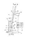
以下、図1〜3を参照して本発明の一実施形態に係る鍵駆動システムについて説明する。図1に示すように、鍵駆動システム1は、鍵盤楽器の手動演奏に際して押鍵に対する反力を調整する役割を果たすものであり、鍵盤楽器の各鍵3に取り付けて構成されている。
鍵盤楽器の各鍵3は、その後端3b側を支点F1としてフレーム(不図示)に対して揺動できるようになっており、鍵3の下方にはフレームに対して揺動可能に取り付けられた揺動レバー5が配置されている。Hereinafter, a lock driving system according to an embodiment of the present invention will be described with reference to FIGS. As shown in FIG. 1, the
Each
揺動レバー5は、その長手方向が鍵3の前後方向となるように配置されており、その中途部を支点F2として揺動できるようにフレームに支持されている。この揺動レバー5は、その前端5aが鍵3の前端3a側に係合しているため、鍵3の揺動に連動して支点F2を中心に揺動することになる。
そして、支点F2よりも揺動レバー5の後端5b側には、例えばアコースティックピアノにおいて弦を叩くハンマー等の錘が取り付けられるようになっており、揺動レバー5の重心は上記支点F2よりも後端5b側にずれている。したがって、鍵3は揺動レバー5の自重によって揺動方向の一方(A方向)に付勢されることになる。すなわち、揺動レバー5は、鍵3をA方向に付勢する付勢手段として機能する。
そして、この鍵盤楽器では、手指により鍵3の表面3cを押して鍵3及び揺動レバー5をA方向とは逆向き(B方向)に揺動させることで、音が発生するようになっている。The
Further, a weight such as a hammer for hitting a string in an acoustic piano is attached to the
In this keyboard instrument, sound is generated by pushing the
鍵駆動システム1は、鍵3の表面3cに対する押し付け圧力を検出する圧力検出センサ11と、鍵3の動作状態を検出する状態検出センサ13と、鍵3を押鍵方向(B方向)に駆動させるアクチュエータ15と、アクチュエータ15を動作させるための参照データを記憶したメモリ部17と、圧力検出センサ11、状態検出センサ13の検出結果やメモリ部17に記憶された参照データに基づいてアクチュエータ15の動作を制御する制御部19とを備えている。 The
圧力検出センサ11は、鍵3の表面3cに取り付けられたフィルム状の感圧センサからなり、この感圧センサは、例えば、手指により鍵3の表面3cを押し付ける圧力を電圧に変換する圧電素子により構成される。圧力検出センサ11を上記感圧センサにより構成することで、鍵3に対する押し付け圧力を直接的に検出することができる。
状態検出センサ13は、鍵3の揺動位置を検出する位置センサからなり、この位置センサは、例えば鍵3の前端3a側の裏面3dに取り付けられて磁界強度を電圧として検出するホール素子21と、ホール素子21に対向してフレームに固定された磁石23とから構成されている。The
The
ホール素子21は、鍵3が押されていない初期位置に配されている状態で磁石23から最も遠くに位置し、鍵3をB方向に揺動させることで磁石23に近づくようになっている。そして、このホール素子21において検出される電圧の大きさは、磁石23から離れている程小さく、磁石23に近づく程大きくなる。したがって、この位置センサにおいては、鍵3の揺動位置を電圧の大きさとして検出することができるようになっている。
なお、上述した位置センサでは、磁石23を鍵3の裏面3dに固定してホール素子21をフレーム側に固定するとしても構わない。また、状態検出センサ13として用いる位置センサでは鍵3の揺動位置を検出できればよいため、位置センサは例えば光学式センサ等により構成されるとしてもよい。The
In the position sensor described above, the
アクチュエータ15は、揺動レバー5の後端5b側の下方に配置されてフレームに固定されたソレノイドコイル25と、ソレノイドコイル25に挿通されて揺動レバー5の後端5bに当接する磁性体のプランジャ27とから構成されている。このアクチュエータ15においては、ソレノイドコイル25に電流を流すことでプランジャ27が揺動レバー5の後端5bを下方から押し上げて、揺動レバー5及び鍵3をB方向に揺動させることができるようになっている。ここで、プランジャ27により揺動レバー5の後端5b側を押し上げる力は、ソレノイドコイル25に流す電流の大きさにより制御することができる。
なお、ソレノイドコイル25に電流が流れていない状態においては、プランジャ27が所定位置に配されて揺動レバー5及び鍵3のA方向への揺動を規制する規制部材としての役割も果たす。The
In the state where no current flows through the
また、メモリ部17には、上述した参照データとして、図3に示すように、発音に要する押鍵圧力(手指の力のみで押鍵する場合の圧力)の時間履歴を示す履歴テーブルG1が、初期段階における鍵3の移動速度(以下、鍵3の初期速度と呼ぶ。)に対応づけて複数記憶されている。具体的には、小さい鍵3の初期速度と小さな音を発生させる履歴テーブルG1とが対応づけられ、大きい鍵3の初期速度と大きな音を発生させる履歴テーブルG1とが対応づけられている。 Further, in the
次に、上述のように構成された鍵駆動システム1により鍵3を駆動制御する方法について以下に説明する。なお、ここで説明する鍵3の駆動制御は、演奏者が手指で押鍵する手動演奏の際に行われるものである。
図2に示すように、はじめに、鍵3が押されていない初期位置に配された状態で、感圧センサが押し付け圧力Pk(N/m2)を検出したか否かを判定する(ステップS1)。すなわち、ステップS1においては、手指が鍵3の表面3cに接触して押し付けられているか否かを判定するようになっている。このステップS1は、押し付け圧力Pkが0よりも大きくなるまで繰り返し行われる。Next, a method for driving and controlling the
As shown in FIG. 2, first, it is determined whether or not the pressure sensor has detected the pressing pressure Pk (N / m2 ) in a state where the
そして、ステップS1において感圧センサが0よりも大きい押し付け圧力Pkを検出したと判定されると、位置センサが鍵3の移動を検出したか否かを判定する(ステップS2)。すなわち、ステップS2においては、手指の動作により鍵3が初期位置からB方向に揺動したか否かを判定するようになっている。このステップS2は、鍵3の初期位置からB方向への揺動長さLk(m)が0よりも大きくなるまで繰り返し行われる。
以上のように、これらステップS1,S2において押し付け圧力Pk及び鍵3の初期位置からの移動の両方が検出されることで、手指での押鍵が開始されたことを制御部19において判定することができる。If it is determined in step S1 that the pressure sensor has detected a pressing pressurePk greater than 0, it is determined whether or not the position sensor has detected movement of the key 3 (step S2). That is, in step S2, it is determined whether or not the key 3 is swung in the B direction from the initial position by the operation of the finger. This step S2 is repeated until the rocking length Lk (m) in the B direction from the initial position of the
As described above, by detecting both the pressing pressure Pk and the movement of the key 3 from the initial position in these steps S1 and S2, the
そして、ステップS2において位置センサが0よりも大きい揺動長さLkを検出したと判定されると、制御部19がステップS2における位置センサの検出結果に基づいて所定の圧力閾値X(N/m2)を設定する(ステップS3)。この圧力閾値Xは、0よりも大きく、かつ、手指の力のみで押鍵して発音させる場合の押鍵圧力よりも小さい値に設定される(図3参照)。すなわち、圧力閾値Xは、押鍵圧力よりも小さい手指の力で押鍵するための設定値となっている。
具体的に、このステップS3では、制御部19が、ステップS2において検出された揺動長さLkに基づいて鍵3の初期速度を算出して、この初期速度に対応する履歴テーブルG1(図3参照)をメモリ部17から読み出し、この履歴テーブルG1を参照して圧力閾値Xを設定する。If it is determined that the position sensor in step S2 has detected a large swing length Lk than 0, the
Specifically, in the step S3, the
このステップS3が完了した後には、感圧センサの検出結果が圧力閾値Xに保持されるように、また、鍵3が押鍵圧力の履歴テーブルG1にあわせて動作するように、制御部19によりアクチュエータ15の動作を制御する。
具体的には、はじめに、制御部19が感圧センサにおいて検出される押し付け圧力Pkと圧力閾値Xとを比較する(ステップS4)。このステップS4において、押し付け圧力Pkが圧力閾値Xよりも小さいと判定された場合には、手指の動きが鍵3のB方向への動きに追従できなくなるため、制御部19の指令によりアクチュエータ15のソレノイドコイル25に供給する駆動電流を減少させる(ステップS5)。ここでは、アクチュエータ15による鍵3の駆動力が減少するため、押し付け圧力Pkが増加して押鍵の際に手指の動きを鍵3の動きに追従させることができる。
なお、このステップS5において、駆動電流が0となっても押し付け圧力Pkが圧力閾値Xよりも小さい場合には、駆動電流を0のままとする。すなわち、ソレノイドコイル25に供給する駆動電流の向きは1方向のみであり、アクチュエータ15により鍵3をA方向に駆動しないようになっている。After the completion of step S3, the
Specifically, first, the
In this step S5, if the pressing pressurePk is smaller than the pressure threshold value X even if the drive current becomes 0, the drive current remains 0. In other words, the direction of the drive current supplied to the
また、ステップS4において押し付け圧力Pkが圧力閾値Xよりも大きいと判定された場合には、制御部19の指令によりアクチュエータ15のソレノイドコイル25に供給する駆動電流を増加させる(ステップS6)。これにより、アクチュエータ15による鍵3の駆動力が増加するため、手指での押鍵に対する反力が圧力閾値Xまで軽減されることになる。
そして、これらステップS5若しくはステップS6の後には、制御部19が位置センサの検出結果に基づいて鍵3の移動速度や加速度を算出し、この鍵3の移動速度や加速度に追従させるようにアクチュエータ15の動作をフィードバック制御する(ステップS7)。このフィードバック制御においてもソレノイドコイル25に流す電流の値が増減する。このステップS7を実施することにより、アクチュエータ15が鍵3の動作を阻害することを確実に防止することができる。すなわち、鍵3の動きが不自然になることを確実に防止することができる。When it is determined in step S4 that the pressing pressurePk is larger than the pressure threshold value X, the drive current supplied to the
After step S5 or step S6, the
そして、上記ステップS7が終了すると、位置センサが鍵3の揺動位置を検出して鍵3が初期位置(Lk=0)まで戻ったか否かを判定する(ステップS8)。ここで、鍵3が初期位置まで戻っていないと判定された場合には、再度ステップS4に戻り、押し付け圧力Pkと圧力閾値Xとを比較する。
また、ステップS8において鍵3が初期位置まで戻ったと判定された場合には、手指による押鍵動作が終了したことになる。When step S7 ends, the position sensor detects the swing position of the
If it is determined in step S8 that the
以上のようにして鍵3の駆動制御を行うことにより、感圧センサにおいて検出される押し付け圧力Pkの時間履歴が図3に示す2点鎖線のようになる。すなわち、押し付け圧力Pkは、圧力閾値X以下である場合に履歴テーブルG1と同じ値となり、この状態においてアクチュエータ15に電流は流れない。また、押し付け圧力Pkが圧力閾値Xに到達している状態においては、アクチュエータ15に電流が流れて押鍵をアシストするように鍵3を駆動している。By performing the drive control of the key 3 as described above, the time history of the pressing pressure Pk detected by the pressure sensor becomes as indicated by a two-dot chain line shown in FIG. That is, when the pressing pressurePk is equal to or lower than the pressure threshold value X, the same value as the history table G1 is obtained, and no current flows through the
上記鍵駆動システム1によれば、手指により押鍵する際に、感圧センサの検出結果である押し付け圧力Pkが押鍵圧力よりも小さい値に設定された圧力閾値Xに保持されるように、制御部19によりアクチュエータ15の動作を制御して鍵3をB方向に移動させるため、発音に要する押鍵圧力よりも小さい力で押鍵して発音させることができる。すなわち、手動演奏の際には、アクチュエータ15の動作により手指による押鍵をアシストして押鍵に対する反力を軽減することができる。
したがって、ハンマー等の重い駆動部品を備えた鍵盤楽器でも高音部や低音部に関わらず素早い打鍵操作を行うことができる。また、演奏者の力にあわせて圧力閾値Xを設定することで力の弱い人でも上記駆動部品を備えた鍵盤楽器を演奏することが可能となる。According to the
Therefore, even a keyboard instrument having a heavy drive component such as a hammer can perform a quick keystroke operation regardless of the high-pitched portion or the low-pitched portion. In addition, by setting the pressure threshold value X in accordance with the player's power, even a person with weak power can play the keyboard instrument provided with the drive component.
また、鍵3の初期速度に対応づけて履歴テーブルG1を予めメモリ部17に記憶させておくことで、位置センサの検出結果に基づく圧力閾値Xの設定を容易に行うことができる。
さらに、小さい鍵の移動速度には小さな音を発生させる履歴テーブルG1を対応づけ、大きい鍵の移動速度には大きな音を発生させる履歴テーブルG1を対応づけてメモリ部17に記憶させてあるため、押鍵の際に鍵3の初期速度を変化させるだけで、押鍵により発生する音の大きさを容易に変化させることができる。Further, by storing the history table G1 in advance in the
Further, since the history table G1 for generating a small sound is associated with the moving speed of the small key and the history table G1 for generating a large sound is associated with the moving speed of the large key and stored in the
なお、上記実施形態において、圧力閾値Xは、鍵3の初期速度に基づいて設定されるとしたが、これに限ることはなく、例えば、鍵3の駆動制御を開始する前に予め所定の値に設定されるとしても構わない。
また、ステップS7におけるアクチュエータ15の動作のフィードバック制御は、位置センサの検出結果に基づいて行われるとしたが、これに限ることはなく、例えば、図3に示すように、押鍵圧力の履歴テーブルG1に対応する鍵3のストロークの時間履歴G2をメモリ部17に予め記憶させておき、ステップS7においては、鍵3の位置が上記ストロークの時間履歴G2に一致するようにアクチュエータ15のフィードバック制御を行うとしても構わない。In the above embodiment, the pressure threshold value X is set based on the initial speed of the
Further, the feedback control of the operation of the
さらに、状態検出センサ13は、鍵3の揺動位置を検出する位置センサからなるとしたが、これに限ることはなく、少なくとも鍵3の動作状態を検出することができれば良く、例えば、鍵3の移動速度や加速度を検出する速度センサや加速度センサからなるとしてもよい。また、状態検出センサはこれら位置センサ、速度センサ、加速度センサを組み合わせて構成されるとしても構わない。
なお、状態検出センサが速度センサからなる場合には、例えば図4に示すように、鍵3の前端3aの下方に固定されたコイル33と、鍵3の前端3a側の裏面3dに固定されて鍵3の揺動に応じてコイル33内を移動する磁石35とにより速度センサ31を構成すればよい。この構成の場合には、鍵3の揺動速度に応じた大きさの誘導起電力がコイル33に発生するため、鍵3の揺動速度を直接検出することができる。
また、状態検出センサが加速度センサからなる場合には、例えば図5に示すように、鍵3の前端3a側の裏面3dにMEMS(Micro Electro Mechanical System)型の加速度センサ37を固定しておけばよい。Furthermore, the
When the state detection sensor is a speed sensor, for example, as shown in FIG. 4, the state detection sensor is fixed to a
When the state detection sensor is an acceleration sensor, for example, as shown in FIG. 5, a MEMS (Micro Electro Mechanical System)
さらに、圧力検出センサ11は、鍵3の表面3cに取り付けられた感圧センサにより構成されるとしたが、これに限ることはなく、少なくとも鍵3に対する押し付け圧力Pkを検出できるように構成されていればよい。
すなわち、圧力検出センサは、例えば、図6に示すように、鍵3の後端3bとフレームとを連結する歪みゲージ41により構成されるとしても構わない。この歪みゲージ41は、例えば圧電素子により構成され、鍵3をB方向に揺動させた際に撓むことでその歪み量を電圧として検出できるようになっている。この歪みゲージ41を圧力検出センサとして使用する場合には、検出された歪み量に基づいて鍵3に対する押し付け圧力Pkを制御部19において算出すればよい。Furthermore, the
That is, for example, as shown in FIG. 6, the pressure detection sensor may be configured by a
また、アクチュエータ15は、揺動レバー5の後端5b側を押し上げるように配されるとしたが、これに限ることはなく、少なくとも鍵3及び揺動レバー5をB方向に揺動させるように配されていればよい。したがって、アクチュエータ15は、例えば図6に示すように、鍵3の前端3a側の下方に配置されるとしても構わない。ただし、この構成の場合には、プランジャ27により鍵3を引っ張ることでB方向に揺動させる必要があるため、プランジャ27を鍵3の裏面3dに連結しておく必要がある。
さらに、アクチュエータ15は、ソレノイドコイル25及びプランジャ27により構成されるとしたが、これに限ることはなく、少なくとも制御部19からの指令に基づいて鍵3及び揺動レバー5をB方向に揺動させる構成であればよい。したがって、アクチュエータ15は、例えば超音波モータや電磁モータ、形状記憶合金、高分子アクチュエータ、表面弾性波モータにより構成されるとしても構わない。In addition, the
Furthermore, although the
以上、本発明の実施形態について図面を参照して詳述したが、具体的な構成はこの実施形態に限られるものではなく、本発明の要旨を逸脱しない範囲の設計変更等も含まれる。 As mentioned above, although embodiment of this invention was explained in full detail with reference to drawings, the concrete structure is not restricted to this embodiment, The design change etc. of the range which does not deviate from the summary of this invention are included.
1・・・鍵駆動システム、3・・・鍵、11・・・圧力検出センサ(感圧センサ)、13・・・状態検出センサ(位置センサ)、15・・・アクチュエータ、17・・・メモリ部、19・・・制御部、31・・・速度センサ(状態検出センサ)、37・・・加速度センサ(状態検出センサ)、41・・・歪みゲージ(圧力検出センサ)、G1・・・履歴テーブルDESCRIPTION OF
Claims (4)
Translated fromJapanese鍵に対する押し付け圧力を検出する圧力検出センサと、
前記鍵の動作状態を検出する状態検出センサと、
前記鍵を押鍵方向に駆動させるアクチュエータと、
前記圧力検出センサが前記押し付け圧力を検出し、かつ、前記状態検出センサが前記鍵の移動を検出した際に、前記圧力検出センサの検出結果を0よりも大きく、かつ、発音に要する押鍵圧力よりも小さくなるように前記状態検出センサの検出結果に基づいて設定された圧力閾値に保持しつつ、前記アクチュエータの動作を制御する制御部とを備えることを特徴とする鍵駆動システム。A key drive system used for a keyboard instrument that produces sound by pressing a key,
A pressure detection sensor for detecting the pressing pressure against the key;
A state detection sensor for detecting an operating state of the key;
An actuator for driving the key in the key-pressing direction;
When the pressure detection sensor detects the pressing pressure and the state detection sensor detects the movement of the key, the detection result of the pressure detection sensor is greater than 0 and the key pressing pressure required for sound generation And a controller that controls the operation of the actuator while maintaininga pressure threshold valueset based on the detection result of the state detection sensor so as to be smaller than the lock driving system.
前記圧力検出センサが前記押し付け圧力を検出し、かつ、前記状態検出センサが前記鍵の移動を検出した際に、前記制御部が、前記状態検出センサの検出結果に基づいて前記鍵の移動速度を算出して該移動速度に対応する前記履歴テーブルを前記メモリ部から読み出し、該履歴テーブルを参照して前記圧力閾値を設定することを特徴とする請求項1から請求項3のいずれか1項に記載の鍵駆動システム。
A memory unit that stores a history table showing a time history of key pressing pressure required for pronunciation in association with the moving speed of the key,
When the pressure detection sensor detects the pressing pressure and the state detection sensor detects the movement of the key, the control unit determines the movement speed of the key based on the detection result of the state detection sensor. calculated by reading the history table corresponding to the moving speed from said memory unit,from claim 1, characterized in that setting the pressure threshold by referring to the subsequent history tableto any one of claims 3 The key drive systemdescribed .
Priority Applications (7)
| Application Number | Priority Date | Filing Date | Title |
|---|---|---|---|
| JP2006239500AJP4225335B2 (en) | 2006-09-04 | 2006-09-04 | Key drive system |
| KR1020070087341AKR100935753B1 (en) | 2006-09-04 | 2007-08-30 | Key drive system |
| EP07017241AEP1895503B1 (en) | 2006-09-04 | 2007-09-03 | Key actuating system |
| CNB2007101488192ACN100527218C (en) | 2006-09-04 | 2007-09-03 | Key actuating system |
| AT07017241TATE498175T1 (en) | 2006-09-04 | 2007-09-03 | KEY ACTIVATION SYSTEM |
| DE602007012390TDE602007012390D1 (en) | 2006-09-04 | 2007-09-03 | Key actuation system |
| US11/896,599US7667116B2 (en) | 2006-09-04 | 2007-09-04 | Key actuating system |
Applications Claiming Priority (1)
| Application Number | Priority Date | Filing Date | Title |
|---|---|---|---|
| JP2006239500AJP4225335B2 (en) | 2006-09-04 | 2006-09-04 | Key drive system |
Publications (2)
| Publication Number | Publication Date |
|---|---|
| JP2008064798A JP2008064798A (en) | 2008-03-21 |
| JP4225335B2true JP4225335B2 (en) | 2009-02-18 |
Family
ID=38544079
Family Applications (1)
| Application Number | Title | Priority Date | Filing Date |
|---|---|---|---|
| JP2006239500AExpired - Fee RelatedJP4225335B2 (en) | 2006-09-04 | 2006-09-04 | Key drive system |
Country Status (7)
| Country | Link |
|---|---|
| US (1) | US7667116B2 (en) |
| EP (1) | EP1895503B1 (en) |
| JP (1) | JP4225335B2 (en) |
| KR (1) | KR100935753B1 (en) |
| CN (1) | CN100527218C (en) |
| AT (1) | ATE498175T1 (en) |
| DE (1) | DE602007012390D1 (en) |
Families Citing this family (32)
| Publication number | Priority date | Publication date | Assignee | Title |
|---|---|---|---|---|
| JP4752562B2 (en)* | 2006-03-24 | 2011-08-17 | ヤマハ株式会社 | Key drive device and keyboard instrument |
| JP4225335B2 (en)* | 2006-09-04 | 2009-02-18 | ヤマハ株式会社 | Key drive system |
| US8248277B2 (en)* | 2007-07-06 | 2012-08-21 | Pacinian Corporation | Haptic keyboard systems and methods |
| US7741979B2 (en) | 2007-07-06 | 2010-06-22 | Pacinian Corporation | Haptic keyboard systems and methods |
| US8199033B2 (en)* | 2007-07-06 | 2012-06-12 | Pacinian Corporation | Haptic keyboard systems and methods |
| JP5135927B2 (en)* | 2007-07-13 | 2013-02-06 | ヤマハ株式会社 | Performance support device and musical instrument |
| US7851690B1 (en)* | 2008-01-15 | 2010-12-14 | Wayne Lee Stahnke | Method and system for automatic calibration of pedal actuator in a reproducing piano |
| US8310444B2 (en) | 2008-01-29 | 2012-11-13 | Pacinian Corporation | Projected field haptic actuation |
| WO2009102992A1 (en)* | 2008-02-15 | 2009-08-20 | Pacinian Corporation | Keyboard adaptive haptic response |
| US8203531B2 (en)* | 2008-03-14 | 2012-06-19 | Pacinian Corporation | Vector-specific haptic feedback |
| JP5194924B2 (en)* | 2008-03-25 | 2013-05-08 | ヤマハ株式会社 | Keyboard device |
| US8760413B2 (en)* | 2009-01-08 | 2014-06-24 | Synaptics Incorporated | Tactile surface |
| JP5560777B2 (en)* | 2009-03-13 | 2014-07-30 | ヤマハ株式会社 | Keyboard instrument |
| JP5532747B2 (en)* | 2009-08-25 | 2014-06-25 | ヤマハ株式会社 | Keyboard device |
| US8624839B2 (en) | 2009-10-15 | 2014-01-07 | Synaptics Incorporated | Support-surface apparatus to impart tactile feedback |
| US10068728B2 (en) | 2009-10-15 | 2018-09-04 | Synaptics Incorporated | Touchpad with capacitive force sensing |
| US8912458B2 (en) | 2011-01-04 | 2014-12-16 | Synaptics Incorporated | Touchsurface with level and planar translational travel responsiveness |
| US8309870B2 (en) | 2011-01-04 | 2012-11-13 | Cody George Peterson | Leveled touchsurface with planar translational responsiveness to vertical travel |
| US8847890B2 (en) | 2011-01-04 | 2014-09-30 | Synaptics Incorporated | Leveled touchsurface with planar translational responsiveness to vertical travel |
| US9218927B2 (en) | 2012-08-06 | 2015-12-22 | Synaptics Incorporated | Touchsurface assembly with level and planar translational responsiveness via a buckling elastic component |
| US9040851B2 (en) | 2012-08-06 | 2015-05-26 | Synaptics Incorporated | Keycap assembly with an interactive spring mechanism |
| WO2014025786A1 (en) | 2012-08-06 | 2014-02-13 | Synaptics Incorporated | Touchsurface assembly utilizing magnetically enabled hinge |
| US9177733B2 (en) | 2012-08-06 | 2015-11-03 | Synaptics Incorporated | Touchsurface assemblies with linkages |
| CN103337239B (en)* | 2013-01-24 | 2015-09-02 | 中音公司 | PAT music keyboard |
| US9384919B2 (en) | 2013-03-14 | 2016-07-05 | Synaptics Incorporated | Touchsurface assembly having key guides formed in a sheet metal component |
| US9213372B2 (en) | 2013-04-19 | 2015-12-15 | Synaptics Incorporated | Retractable keyboard keys |
| US9966052B2 (en)* | 2014-02-12 | 2018-05-08 | Rodrigo Vázquez Díaz | Keyboard with adjustable touch for a musical instrument |
| JP6024997B2 (en)* | 2014-09-22 | 2016-11-16 | カシオ計算機株式会社 | Musical sound control device, musical sound control method, program, and electronic musical instrument |
| WO2017121049A1 (en) | 2016-01-15 | 2017-07-20 | Findpiano Information Technology (Shanghai) Co., Ltd. | Piano system and operating method thereof |
| US10847126B2 (en)* | 2017-03-23 | 2020-11-24 | Indiana University Research And Technology Corporation | Hands-free vibraphone modulator |
| JP7436344B2 (en)* | 2020-10-27 | 2024-02-21 | ローランド株式会社 | Keyboard device and load application method |
| CN114566078B (en)* | 2022-03-11 | 2022-08-26 | 牡丹江师范学院 | Teaching aid convenient for music teaching and teaching method thereof |
Family Cites Families (25)
| Publication number | Priority date | Publication date | Assignee | Title |
|---|---|---|---|---|
| JP2893702B2 (en) | 1989-03-06 | 1999-05-24 | ヤマハ株式会社 | Electronic musical instrument operating device |
| JP2560828B2 (en) | 1989-03-29 | 1996-12-04 | ヤマハ株式会社 | Sensor device for automatic playing piano |
| JP2956180B2 (en)* | 1990-09-18 | 1999-10-04 | ヤマハ株式会社 | Electronic musical instrument |
| JPH04204697A (en) | 1990-11-30 | 1992-07-27 | Casio Comput Co Ltd | Electronic musical instrument |
| JP3191327B2 (en) | 1991-07-02 | 2001-07-23 | ヤマハ株式会社 | Operation device |
| JP3316517B2 (en) | 1992-06-15 | 2002-08-19 | カシオ計算機株式会社 | Keyboard device |
| JPH0916177A (en)* | 1995-06-29 | 1997-01-17 | Kawai Musical Instr Mfg Co Ltd | Keyboard instrument |
| JP3852441B2 (en) | 1996-10-18 | 2006-11-29 | ヤマハ株式会社 | Keyboard force sense control device and storage medium |
| US6888052B2 (en)* | 1998-09-04 | 2005-05-03 | David Meisel | Key actuation systems for keyboard instruments |
| US6781046B2 (en)* | 1998-09-04 | 2004-08-24 | David Meisel | Key actuation systems for keyboard instruments |
| US20060272469A1 (en)* | 1998-09-04 | 2006-12-07 | David Meisel | Key actuation systems for keyboard instruments |
| US6194643B1 (en)* | 1998-09-04 | 2001-02-27 | David Meisel | Key actuation systems for keyboard instruments |
| NL1011484C1 (en)* | 1999-03-08 | 2000-09-12 | Henri Jan Velo | Wing mechanism with permanent magnets. |
| SI20444A (en)* | 2001-03-20 | 2001-06-30 | Antun Merkoci | Upright piano action, providing response adjusment of each individual key or keys |
| US7166795B2 (en)* | 2004-03-19 | 2007-01-23 | Apple Computer, Inc. | Method and apparatus for simulating a mechanical keyboard action in an electronic keyboard |
| JP4506619B2 (en)* | 2005-08-30 | 2010-07-21 | ヤマハ株式会社 | Performance assist device |
| JP5023528B2 (en)* | 2006-03-24 | 2012-09-12 | ヤマハ株式会社 | Wind instrument support structure |
| JP4752562B2 (en)* | 2006-03-24 | 2011-08-17 | ヤマハ株式会社 | Key drive device and keyboard instrument |
| JP4475248B2 (en)* | 2006-03-31 | 2010-06-09 | ヤマハ株式会社 | Wind instrument support structure |
| JP4207063B2 (en) | 2006-07-20 | 2009-01-14 | ヤマハ株式会社 | Performance assist device and musical instrument |
| JP4225335B2 (en)* | 2006-09-04 | 2009-02-18 | ヤマハ株式会社 | Key drive system |
| JP4894448B2 (en)* | 2006-10-12 | 2012-03-14 | ヤマハ株式会社 | Performance assist device and musical instrument |
| JP5066966B2 (en)* | 2007-03-23 | 2012-11-07 | ヤマハ株式会社 | Performance support device, controller and program |
| US7858864B2 (en)* | 2007-03-23 | 2010-12-28 | Yamaha Corporation | Key actuating apparatus |
| JP5056197B2 (en)* | 2007-06-22 | 2012-10-24 | ヤマハ株式会社 | Performance support apparatus and performance apparatus |
- 2006
- 2006-09-04JPJP2006239500Apatent/JP4225335B2/ennot_activeExpired - Fee Related
- 2007
- 2007-08-30KRKR1020070087341Apatent/KR100935753B1/ennot_activeExpired - Fee Related
- 2007-09-03DEDE602007012390Tpatent/DE602007012390D1/enactiveActive
- 2007-09-03EPEP07017241Apatent/EP1895503B1/ennot_activeNot-in-force
- 2007-09-03CNCNB2007101488192Apatent/CN100527218C/ennot_activeExpired - Fee Related
- 2007-09-03ATAT07017241Tpatent/ATE498175T1/ennot_activeIP Right Cessation
- 2007-09-04USUS11/896,599patent/US7667116B2/enactiveActive
Also Published As
| Publication number | Publication date |
|---|---|
| CN101140754A (en) | 2008-03-12 |
| DE602007012390D1 (en) | 2011-03-24 |
| US20080092720A1 (en) | 2008-04-24 |
| EP1895503A1 (en) | 2008-03-05 |
| ATE498175T1 (en) | 2011-02-15 |
| KR20080021539A (en) | 2008-03-07 |
| KR100935753B1 (en) | 2010-01-06 |
| JP2008064798A (en) | 2008-03-21 |
| CN100527218C (en) | 2009-08-12 |
| EP1895503B1 (en) | 2011-02-09 |
| US7667116B2 (en) | 2010-02-23 |
Similar Documents
| Publication | Publication Date | Title |
|---|---|---|
| JP4225335B2 (en) | Key drive system | |
| JP5223490B2 (en) | Force control device for pedal of electronic keyboard instrument | |
| JP5487712B2 (en) | Performance support device | |
| JP5135927B2 (en) | Performance support device and musical instrument | |
| JP5028849B2 (en) | Method and apparatus for identifying half point of pedal of keyboard instrument | |
| KR20040086575A (en) | Automatic player keyboard musical instrument equipped with key sensors shared between automatic playing system and recording system | |
| JP4375200B2 (en) | Basic information output device for haptic control | |
| US8546679B2 (en) | Keyboard musical instrument, program, performance data conversion program and device | |
| JP5422969B2 (en) | Electronic keyboard instrument | |
| JP5104261B2 (en) | Keyboard instrument and control method of keyboard instrument | |
| JP2008116814A (en) | Keyboard instrument | |
| JP5212024B2 (en) | Electronic keyboard instrument | |
| JP5272439B2 (en) | Force sensor | |
| JP4345690B2 (en) | Keyboard instrument and operating element reaction force optimization system | |
| JP5532747B2 (en) | Keyboard device | |
| JP2011237493A (en) | Keyboard device | |
| JP5572941B2 (en) | Force controller for electronic keyboard instrument | |
| JP2007256869A (en) | Key driving device and keyboard musical instrument | |
| JP2008157999A (en) | Key driving device and keyboard device | |
| JP5412990B2 (en) | Keyboard device | |
| JP5387164B2 (en) | Keyboard device | |
| JP5310304B2 (en) | Keyboard device | |
| JP2009047753A (en) | Key actuating apparatus |
Legal Events
| Date | Code | Title | Description |
|---|---|---|---|
| A977 | Report on retrieval | Free format text:JAPANESE INTERMEDIATE CODE: A971007 Effective date:20080801 | |
| A131 | Notification of reasons for refusal | Free format text:JAPANESE INTERMEDIATE CODE: A131 Effective date:20080812 | |
| A521 | Request for written amendment filed | Free format text:JAPANESE INTERMEDIATE CODE: A523 Effective date:20081009 | |
| TRDD | Decision of grant or rejection written | ||
| A01 | Written decision to grant a patent or to grant a registration (utility model) | Free format text:JAPANESE INTERMEDIATE CODE: A01 Effective date:20081104 | |
| A01 | Written decision to grant a patent or to grant a registration (utility model) | Free format text:JAPANESE INTERMEDIATE CODE: A01 | |
| A61 | First payment of annual fees (during grant procedure) | Free format text:JAPANESE INTERMEDIATE CODE: A61 Effective date:20081117 | |
| FPAY | Renewal fee payment (event date is renewal date of database) | Free format text:PAYMENT UNTIL: 20111205 Year of fee payment:3 | |
| R150 | Certificate of patent or registration of utility model | Ref document number:4225335 Country of ref document:JP Free format text:JAPANESE INTERMEDIATE CODE: R150 Free format text:JAPANESE INTERMEDIATE CODE: R150 | |
| FPAY | Renewal fee payment (event date is renewal date of database) | Free format text:PAYMENT UNTIL: 20111205 Year of fee payment:3 | |
| FPAY | Renewal fee payment (event date is renewal date of database) | Free format text:PAYMENT UNTIL: 20121205 Year of fee payment:4 | |
| FPAY | Renewal fee payment (event date is renewal date of database) | Free format text:PAYMENT UNTIL: 20131205 Year of fee payment:5 | |
| LAPS | Cancellation because of no payment of annual fees |