JP4224759B2 - Cell washing rotor, washing liquid distribution element used therefor, and cell washing centrifuge equipped with the same - Google Patents
Cell washing rotor, washing liquid distribution element used therefor, and cell washing centrifuge equipped with the sameDownload PDFInfo
- Publication number
- JP4224759B2 JP4224759B2JP2002142781AJP2002142781AJP4224759B2JP 4224759 B2JP4224759 B2JP 4224759B2JP 2002142781 AJP2002142781 AJP 2002142781AJP 2002142781 AJP2002142781 AJP 2002142781AJP 4224759 B2JP4224759 B2JP 4224759B2
- Authority
- JP
- Japan
- Prior art keywords
- distribution element
- rotor
- cleaning liquid
- central
- washing
- Prior art date
- Legal status (The legal status is an assumption and is not a legal conclusion. Google has not performed a legal analysis and makes no representation as to the accuracy of the status listed.)
- Expired - Lifetime
Links
Images


Landscapes
- Investigating Or Analysing Biological Materials (AREA)
- Cleaning In General (AREA)
- Cleaning By Liquid Or Steam (AREA)
- Apparatus Associated With Microorganisms And Enzymes (AREA)
- Centrifugal Separators (AREA)
- Feeding, Discharge, Calcimining, Fusing, And Gas-Generation Devices (AREA)
Description
Translated fromJapanese【0001】
【発明の属する分野】
本発明は遠心力を利用して赤血球等の生体細胞を洗浄する細胞洗浄遠心機に係り、更にはそれに用いられる細胞洗浄ロータ及び洗浄液を分配する洗浄液分配素子に関する。
【0002】
【従来の技術】
従来から,輸血検査時の抗グロブリン試験、交差適合試験、不規則抗体スクリーニング等には赤血球を生理食塩水等の洗浄液で洗浄し、懸濁液中の余分な抗体を除去する工程が必要であり、この目的のために色々な細胞洗浄遠心機が知られている。
例えば、特開昭50−22693号公報には、内面が円錐形状容器の底面外周から放射状にノズルを設置し、回転による遠心力で洗浄液分配素子中央から注入された洗浄液を等分に分配し、ノズルより試験管ホルダによって保持された多数の試験管内に洗浄液を供給する構造の洗浄液分配素子が開示されている。
また例えば、実開平2−81640号公報には、洗浄液分配素子に穿孔された穴から試験管ホルダによって保持された多数の試験管内に洗浄液を供給する構造が開示されている。
【0003】
【発明が解決しようとする課題】
細胞洗浄の自動化を目的とした遠心機により良好な輸血検査等を行うためには、洗浄液分配素子により多数の試験管内に供給される洗浄液量が等量であることが望ましい。多数の試験管内に供給された洗浄液量にばらつきがある場合、例えば、洗浄液供給量の少ない試験管内では、懸濁液中に他の試験管よりも多量の抗体などの異物が残留する。また逆に洗浄液供給量の多い試験管内では、懸濁液中の抗体などの残留異物が少なく、この差が後工程で行われる試薬反応による検査結果の差となり、結果として輸血検査等の判定に重大な誤りを生ずる原因となる。また洗浄液量の少ない試験管があった場合、この試験管の洗浄液供給量に合わせて他の試験管にも洗浄液を供給すると、他の試験管には過多の洗浄液が供給され、洗浄液量の多いものは試験管からあふれ、貴重な細胞試料が失われてしまうという問題を生じる。更には、洗浄液量の少ないものに合わせて洗浄回数を決めると洗浄工程が長時間に及ぶ不具合がある。
このように試験管に供給される洗浄液量が不均一になる原因はいくつか考えられる。第一の原因は、洗浄液分配素子の流路抵抗の不均一さに起因するものである。例えば、実開平2−81640号公報で示される放射状に穿孔された穴から試験管ホルダによって保持された多数の試験管内に洗浄液を供給する方式の洗浄液分配素子では、穴の加工はドリル加工などの機械加工以外では困難である。しかし機械加工による穴加工は、穴の出入り口形状や穴内面の粗さに誤差が生じやすく、これが不均一な流路抵抗の原因となり、結果として多数の試験管内に供給された洗浄液量にばらつきを生じさせる。
また、特開昭50−22693号公報には、洗浄液分配素子に金属パイプを埋め込み、金属パイプ内を流路として多数の試験管内に洗浄液を供給する構造が開示されているが、この場合もやはりパイプ端面の加工形状やパイプ長さに加工誤差が生じ、これが前記同様不均一な流路抵抗の原因となり、結果として多数の試験管内に供給された洗浄液量にばらつきを生じさせる。
洗浄液量が不均一になる第二の原因は、洗浄液の漏れに起因するものである。例えば洗浄液分配素子の洗浄液出口と試験管口の距離が離れていると、穴加工方向の誤差により液体分配素子からでた洗浄液が試験管に完全に入らない場合があり、これもやはり試験管内に供給された洗浄液量にばらつきを生じさせる原因となっている。
また金属パイプ先端を試験管の近くに設置し、洗浄液が試験管に完全に入るようにした場合、試験管の長さ寸法のばらつきや回転起動時、試験管ホルダの横方向のがたにより試験管と金属パイプ先端が接触し、試験管破損を引き起こす不具合が発生する。
洗浄液量が不均一になる第三の原因は洗浄液中の異物に起因するものである。ポンプが送り出した洗浄液が液体分配素子に到達する間に空気中のごみや綿ほこり等を巻き込み、それらの異物が洗浄液分配素子の穴やパイプに詰まると、流路を塞ぎ、結果としてその部分に対応する試験管への洗浄液供給量を減少させる。その他、異物の原因として洗浄液に生理食塩水等を用いる場合にはタンクや流路中で析出した塩化ナトリウム等の固形物が流路を塞ぎ、洗浄液供給量を減少させる原因となることもある。
上記の洗浄液分配素子では、外部からこのような流路を塞ぐ異物を見ることが出来ず、定期的に洗浄工程を一時停止し、試験管に分配された洗浄液供給量を確認する煩雑な作業が必要であった。更には、上記の洗浄液分配素子では、処理する試験管本数の増減に関係無く、穴またはパイプの数だけ常に、洗浄液が供給されるため、試験管本数の少ない場合は洗浄液の無駄が生じた。
本発明の目的は上述した従来技術の問題に鑑み、多数の試験管内に、均等な洗浄液量を供給できる洗浄液分配素子を提供することにある。
本発明の他の目的は上記のような洗浄液分配素子を用いることにより、洗浄特性の良好でかつ信頼性が高く、しかも容易に試験管本数の増減に対応できる細胞洗浄ロータ並びにこれを備えた細胞洗浄遠心機を提供することである。
【0004】
【課題を解決するための手段】
上記の目的を達成するために本発明は、試験管内に洗浄液を供給する洗浄液分配素子を、中央部に洗浄液導入孔を有する円錐形状をした第1の部分とその周囲に円形平板状をした第2の部分とからなる上部分配素子と、上記第2の部分と対向するように配置された中央部が中空の円形平板からなる中央部分配素子と、円錐形状をし、上記の第1の部分と対向する位置に配置され、該第1の部分との間に流体通路を形成する下部分配素子とより構成し、前記上部分配素子の第2の部分の下面及び上記中央部分配素子の上面の一方または両方に放射状の複数の溝を設け、上記溝を流体の分配流路としたことに一つの特徴がある。
このように構成すると上部分配素子及び中央部分配素子及び下部分配素子を樹脂またはセラミックス等により成形加工して製造することが可能になり、極めて精度の高い流路を形成できるので流路抵抗を均一化できるという顕著な効果が得られる。特に上部分配素子または中央部分配素子の一方に設けられた溝と、他方の素子の平面により囲まれた空間を洗浄液の流路とした場合にその効果が大きい。本発明の他の特徴は、上部分配素子または下部分配素子の一方または両方に設けられた複数の溝の中心線を、試験管ホルダ中心とロータ中心を結ぶ直線と一致しないようしたことにある。具体的には、溝の中心線を、試験管ホルダ中心とロータ中心を結ぶ直線よりも、ロータの回転方向に前進した位置に設けたことに他の特徴がある。このように構成することにより、洗浄液の漏れを防止できるという効果がある。
本発明の他の特徴は、上部分配素子及び下部分配素子の一方または両方に設けられた複数の溝の中心線を、直線又は曲線状でロータ中心を通る直線とある角度を成すようにしたことにある。これも洗浄液の漏れの防止に効果がある。
本発明の更に他の特徴は、複数の溝の、ロータ中心側の溝端部をなめらかな曲面で構成したことにある。この構成は流路抵抗を減少し、洗浄液量を均一化するのに効果がある。
本発明の更に他の特徴は、上部分配素子の一部または全部を透明部材で構成したことにある。この構成により、異物が流路を塞いでいるかどうかを簡単に判断することが可能になる。
本発明の更に他の特徴は、上部分配素子の中央に円筒形状の把握部を設け、その把握部の外周の縦方向にすべり止めのための複数のすべり止め凹部またはすべり止め凸部を形成したことにある。これは、試薬反応を促進するために手動で細胞洗浄ロータを正逆回転するときに便利な構造である。
本発明の更に他の特徴は、中央部分配素子の最外周において、溝が配置された部分を他の部分よりも外に向かって凸形状にしたことにある。このように構成すると、洗浄液分配素子から試験管に洗浄液が入りやすくなり洗浄液の漏れを防止するのに効果がある。
【0005】
本発明の更に他の特徴は、中央部分配素子の上面及び下面に、上部分配素子及び下部分配素子の位置決め用の凸部または凹部と係合するための凹部または凸部を設けたことにある。このように構成すると各分配素子の位置関係を一義的に定め得る効果がある。
本発明の更に他の特徴は、中央分配素子の一部または全部は弾性体材料から構
成したことにある。これにより、試験管の破損を防止することができる。
【0006】
本発明の更に他の特徴は、中央部分配素子の外形寸法を上部分配素子及び下部分配素子の外形寸法より大きくしたことにある。これにより洗浄液の漏れを防止するのに効果がある。
本発明の更に他の特徴は、上部分配素子及び中央部分配素子及び溝に係合し流体の流れを阻止する栓部材を備えたこと及びその栓部材を弾性体材料から構成したことにある。このように構成することにより試験管数の増減に容易に対応することが可能になる。
【0007】
【発明の実施の形態】
以下本発明の実施例を図面に基づいて説明する。図1は本発明の一実施例を示す細胞洗浄ロータの構造及び部品構成を説明する斜視図である。本実施例では、細胞洗浄ロータ1はロータ2と洗浄液分配素子5から構成され、円盤型のロータ2には外周に24個の角穴が配置され、この穴に24個の試験管ホルダ3が装着されている。試験管4を挿入した試験管ホルダ3はロータ2の回転時、遠心力で装着部を軸として水平方向に自在に動くことができる。この実施例ではロータ2及び試験管ホルダ3はステンレス板をプレス加工により製作したが、樹脂成形品での製作も可能である。ロータ2の上には試験管4に洗浄液を供給する為の洗浄液分配素子5が装着される。洗浄液分配素子5はその下部の凸部がロータ2の長穴と係合しているため、ロータ2と共に回転する。また、洗浄液分配素子5をロータより着脱しても、ロータ2及び試験管ホルダ3と洗浄液分配素子5の位置関係は変わることは無い。
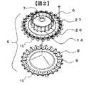
図2は本発明の一実施例を示す洗浄液分配素子の構造及び部品構成を説明する斜視図である。本実施例では、洗浄液分配素子5は上部分配素子6と下部分配素子8から構成され、下部分配素子8には放射状に試験管4の本数に等しい24本の溝9が形成されている。上部分配素子6と下部分配素子8を組み合わせ配置することにより、下部分配素子8の溝9と上部分配素子6の平坦部で構成される空間が洗浄液の流路となる。この実施例により、洗浄液流路を溝と平面で囲まれる形状とすることで、上部分配素子6と下部分配素子8を樹脂成形のみで製作することが可能となる。高精度の金型を用いて上部分配素子6及び下部分配素子8を樹脂成形することにより、下部分配素子8の溝9の形状は、同一の洗浄液分配素子5で高精度に均一となり、性能的に均一な流路抵抗を有する洗浄液分配素子5を何時でも、大量に製造することが可能となった。
なお、上記の実施例において溝は、上部分配素子6及び下部分配素子8の一方又は両方に設けてもよいし、これらを樹脂ではなくセラミックス等で製造することも可能である。作り易さや流路抵抗の均一さを考えると、上記の実施例のように下部分配素子8に溝を設け、上部分配素子6の平面との間に形成される空間を流路とするのが最もよい。
また図2において上部分配素子6の中央には円筒形状の把握部14が設けられている。把握部14の外周には縦方向に複数のすべり止め凹部26とすべり止め凸部27が設けられている。これは、細胞洗浄工程終了後にロータ1を手動で小刻みに正逆回転し、試験管4内の赤血球と試薬を良好に混ぜ合わせ、反応を促進させるときに便利である。
図10は本発明に係る細胞洗浄遠心機20の全体構成を示す縦断面図である。図10を用い洗浄液分配素子5の機能をより詳細に説明する。図10においてモータ21の駆動軸22に細胞洗浄ロータ1が取りつけられる。モータ21には本図では図示しない駆動回路より駆動電圧が印可されて駆動軸22が回転される。細胞洗浄ロータ1は駆動軸22により回転駆動され、試験管ホルダ3及び前もって赤血球等の生体細胞を適量入れた試験管4が遠心力で水平方向に揺動される。
この時にポンプ23を動作させ、外部の洗浄液タンクより洗浄液を細胞洗浄遠心機20の上部に位置するノズル25に送り込むと、洗浄液はノズル25から下方に噴出し、回転している細胞洗浄ロータ1中央の洗浄液導入孔7から洗浄液分配素子5内に入る。洗浄液分配素子5内に入った洗浄液は遠心力により外周に移動し、下部分配素子8の溝9と上部分配素子6の平坦部で構成される24本の流路に分かれて流入し、洗浄液分配素子5の外周から勢い良く飛び出る。飛び出た洗浄液は洗浄液分配素子5の外側に位置する試験管4の内壁に当たり、壁面を伝わり試験管4底部にある生体細胞を浮遊させ懸濁状態を作り出す。試験管4に適量の洗浄液が入るとポンプ23は停止し、洗浄液の注入工程は終了する。
引き続き、浮遊している生体細胞が試験管4底部に集まるまで回転を継続する。その後回転を停止し、試験管ホルダ3を垂直な位置に戻す。次に、本実施例では試験管ホルダ3の水平方向の動きを拘束する手段としの磁気素子28を機能させながら低速でモータ21を回転させる。試験管ホルダ3は磁性体のSUS430材等で製造されているので磁気素子28の磁力により吸着され、垂直な状態または、試験管4の開口部をやや外側に傾けるように保持したまま回転するため試験管4内の洗浄液は遠心力で外部に放出される。試験管4底部にある生体細胞はそのまま残り洗浄液だけが無くなる。
このような工程を繰り返すことにより細胞洗浄遠心機20は試験管4内の生体細胞から抗体などの異物を分離、取り除く。この様な工程により洗浄処理を行うため、多数の試験管内に供給された洗浄液量が等量であることが細胞洗浄遠心機20の性能上望ましい訳である。
図2の実施例によれば、洗浄液分配素子5の上部分配素子6と下部分配素子7が高精度の樹脂成形品で製作されているので、穿孔された穴や金属パイプの流路に比較して下部分配素子8の溝9の形状は高精度に均一とすることができる。従って、穿孔された穴や金属パイプの流路に比較して流路抵抗が均一で等量の洗浄液量を分配することが可能な洗浄液分配素子5を再現性良く、大量に製造することが可能となる。
また細胞洗浄遠心機20の細胞洗浄工程終了後には、例えば赤血球洗浄後には抗グロブリン血清等の試薬を試験管4に滴下し、細胞洗浄ロータ1を手動で小刻みに正逆回転し、試験管4内の赤血球と試薬を良好に混ぜ合わせ、反応を促進させることが必要であるが、図2の実施例では、上部分配素子6の中央に把握部14を設け、更に外周にすべり止め凹部26とすべり止め凸部27を設けたことにより、手動で小刻みに正逆回転することが容易となり、確実な試薬反応を促すことができるという効果がある。
図3は本発明の一実施例による細胞洗浄ロータの平面図である。細胞洗浄遠心機20の処理時間を短縮するためモータ21の回転速度を上げると、洗浄液分配素子5の外周から飛び出た洗浄液が試験管4に入るまでに回転の風圧により飛行方向が曲げられ、完全に試験管4内に入らない場合が発生する。図3の実施例では、溝9の中心線10が、試験管ホルダ3の中心とロータ2の回転中心を結ぶ直線よりも、ロータ2の回転方向に前進した位置に溝9が設けられている。このようにすることにより、洗浄液の飛行方向の曲がりを補正し、図に示すように試験管4の中に確実に注入することができる。前進させる角度はロータ2の回転速度及び洗浄液分配素子5と試験管4の距離に依存するが、0.5度から5度が望ましく、更には言えば1度から3度が望ましい。
図4は本発明の一実施例による細胞洗浄ロータの平面図であり、溝9の中心線10は直線又は曲線状で前記ロータ中心を通る直線とある角度を成して設置されている。この例もやはり溝の中心線10と前記ロータ中心を通る直線とのなす角度をロータ2の回転方向に前進させることで洗浄液の飛行方向の曲がりを補正することができる。
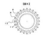
図5は本発明の一実施例による下部分配素子8の平面図である。この実施例においては、溝9の、ロータ2中心側の溝端部11がなめらかな曲面で構成されている。このような形状とすることにより、洗浄液が洗浄液導入孔7から洗浄液分配素子5内に入り、複数の溝9に流れ込む時の流路抵抗のばらつきを小さく押さえ込むことができる。特にこの実施例のように隣り合う溝端部11間を半円状の円弧で構成すると流路抵抗のばらつきを低減するのに効果がある。
また図5及び図2において上部分配素子6及び下部分配素子8は、その最外周において、溝9が配置された部分を他の部分よりも外に向かって凸形状とするような凸部15が設けられている。このような形状とすることにより、試験管4と洗浄液分配素子5が干渉する距離を小さくすることができる。結果として洗浄液分配素子5と試験管4との間の距離を小さく設定でき、凸部15から飛び出た洗浄液が試験管4に入るまでに回転の風圧により飛行方向が曲げられ、試験管4内に入らないという不具合も減少した。また洗浄液分配素子5外周の無駄な部分を削除でき、結果として洗浄液分配素子5の重量の軽量化により、モータ21の負荷を軽減できた。
図6は本発明の一実施例による洗浄液分配素子5の断面図である。上部分配素子6の中央に位置する洗浄液導入孔7に上方から着脱自在な多孔質フィルタ12を装着した。このような構成とすることで洗浄液中の異物は洗浄液分配素子5に入り込む前に除去することが可能で、溝9に詰まり、流路を塞ぎ、結果として試験管4への洗浄液供給量を減少させることを防止できた。本実施例では多孔質フィルタ12は濾過精度50μmのポリプロピレン樹脂燒結成形品を用い、長期間使用後、フィルタの目詰まりが発生し、流量が減少する前に新しいものと交換可能とした。この他、多孔質フィルタ12はステンレス等金属のスクリーンメッシュで製造しても実用上問題は無い。
また図6において上部分配素子6は全て透明部材で製造されている。この結果、上方より下部分配素子8の溝9を目視でき、万が一洗浄液中の異物で流路を塞がれた場合でもその位置を瞬時に特定でき、早期に対処可能となる。溝9が観察可能であれば上部分配素子6の一部だけが透明部材で構成されていても同様の効果を得ることができる。
図7は本発明の他の実施例による洗浄液分配素子の構造及び部品構成を説明する斜視図である。前述した細胞洗浄ロータ1は24個の試験管ホルダ3を保持していたが、必ずしも1回の洗浄処理に24本の試験管4の洗浄処理は行わず、場合によっては12本の試験管4を処理することもある。この場合試験管4の無い部位にも洗浄液は供給注入されるため、洗浄液の無駄が生じた。
図7における実施例では洗浄液分配素子5は上部分配素子6と下部分配素子8及び栓部材16で構成され、栓部材16は上部分配素子6と下部分配素子8の間に保持され、かつ溝端部11に密着、係合した構造とされている。この結果、栓部材16が係合した溝9の洗浄液流れを完全に止めることができた。従って24個の試験管ホルダ3を有する細胞洗浄ロータ1において12本の試験管4を用い洗浄処理を行う場合は、試験管4の設置されていない12個所の溝端部11に栓部材16を密着係合することにより、洗浄液部の無駄な供給を止めることができる。もちろん栓部材16は細胞洗浄ロータ1中心に対して対称な位置に設置することが望ましい。更に、上部分配素子6は、その一部または全部が透明部材で構成されているので、上方より栓部材16の位置を確認でき、確実に試験管4を洗浄液供給個所に設置することができる。また栓部材16はシリコンゴム等の弾性体材料から構成することにより、更に溝端部11との密着性を向上し、確実に洗浄液流れを止めることができる。
図8は本発明の他の実施例による洗浄液分配素子の構造及び部品構成を説明する斜視図である。図8における実施例では洗浄液分配素子5は上部分配素子6と下部分配素子8及び溝9が形成された中央部分配素子17から構成される。このような構成とすることで、洗浄液分配素子5は異なる溝本数を有する中央部分配素子17を逐次交換することにより、簡単に試験管処理本数の増減に対応でき、結果として洗浄液部の無駄を確実に無くすことができる。
また図9は本構成の洗浄液分配素子5の断面図である。中央部分配素子17は上部分配素子6及び下部分配素子8の位置決め凸部18または位置決め凹部19と結合し、その位置関係が一義的に決まるので中央部分配素子17を交換した場合でも対応する試験管4の相対位置に変化は無く、試験管4を洗浄液が供給されない位置に設置する誤りは無くなる。
また中央部分配素子17はその外形寸法が上部分配素子6及び下部分配素子8よりも大きく、溝9が配置された部分が他の部分よりも外に向かって凸であるように構成されている。この結果、試験管4と洗浄液分配素子5が干渉する距離を小さくすることができ、結果として洗浄液分配素子5と試験管4間距離を小さく設定でき、凸部15から飛び出た洗浄液が試験管4に入るまでに回転の風圧により飛行方向が曲げられ、試験管4内に入らない不具合も減少した。更に、中央部分配素子17をシリコンゴム等の弾性体材料で構成することにより試験管4が中央部分配素子17に接する距離に配置しても試験管4は破損することが無くなり信頼性を向上することができる。
また上部分配素子6の洗浄液導入孔7に多孔質フィルタ12を装着したことで洗浄液中の異物の除去可能となり、溝9に詰まり、流路を塞ぎ、結果として試験管4への洗浄液供給量を減少させることを防止できる。更に上部分配素子6を透明部材で製造した結果、万が一洗浄液中の異物で流路を塞がれた場合でもその位置を瞬時に特定でき、早期に対処可能となった。
【0008】
【発明の効果】
以上、説明したように本発明においては、洗浄液分配素子を、中央に洗浄液導入孔を有する円形平板状の上部分配素子と円形平板状の下部分配素子とから構成し、上部分配素子及び下部分配素子のいずれか一方または両方に放射状の複数の溝を設けた構造にするか、あるいは中央に洗浄液導入孔を有する円形平板状の上部分配素子と、複数の放射状に配置された溝を有する円形平板状の中央部分配素子と、円形平板状の下部分配素子からなる構造とすることにより、流路を高精度に形成することが可能になった。
このため、多数の試験管内に均等な洗浄液量を供給できるようになり、その結果、洗浄特性が良好で且つ信頼性が高く、しかも容易に試験管本数の増減に対応できる細胞洗浄ロータ並びにこれを備えた細胞洗浄遠心機を提供することができるという顕著な効果がある。
【図面の簡単な説明】
【図1】本発明の一実施例を示す細胞洗浄ロータの構造及び部品構成を説明する斜視図である。
【図2】本発明の一実施例を示す洗浄液分配素子の構造及び部品構成を説明する斜視図である。
【図3】本発明の一実施例による細胞洗浄ロータの平面図である。
【図4】本発明の一実施例による細胞洗浄ロータの平面図である。
【図5】本発明の一実施例による下部分配素子の平面図である。
【図6】本発明の一実施例による洗浄液分配素子の断面図である。
【図7】本発明の他の実施例による洗浄液分配素子の構造及び部品構成を説明する斜視図である。
【図8】本発明の他の実施例による洗浄液分配素子の構造及び部品構成を説明する斜視図である。
【図9】本発明の他の実施例による洗浄液分配素子の断面図である。
【図10】本発明の一実施例による細胞洗浄遠心機の断面図である。
【符号の説明】
1 細胞洗浄ロータ
2 ロータ
3 試験管ホルダ
4 試験管
洗浄液分配素子
上部分配素子
洗浄液導入孔
下部分配素子
9 溝
10 中心線
11 溝端部
12 多孔質フィルタ
13 透明部材
14 把握部
15 凸部
16 栓部材
17 中央部分配素子
18 位置決め凸部
19 位置決め凹部
20 細胞洗浄遠心機
21 モータ
22 駆動軸
23 ポンプ
25 ノズル
26 すべり止め凹部
27 すべり止め凸部
28 磁気素子
29 回り止め凸部
30 長穴[0001]
[Field of the Invention]
The present invention relates to a cell washing centrifuge that uses a centrifugal force to wash biological cells such as erythrocytes, and further relates to a cell washing rotor used therein and a washing liquid dispensing element that dispenses washing liquid.
[0002]
[Prior art]
Conventionally, for anti-globulin test, cross-match test, irregular antibody screening, etc. at the time of blood transfusion test, it is necessary to wash the red blood cells with a washing solution such as physiological saline and remove the excess antibody in the suspension. Various cell washing centrifuges are known for this purpose.
For example, in Japanese Patent Application Laid-Open No. Sho 50-22669, nozzles are radially installed from the outer periphery of the bottom surface of a conical container, and the cleaning liquid injected from the center of the cleaning liquid distribution element is distributed equally by centrifugal force due to rotation, A cleaning liquid distribution element having a structure for supplying a cleaning liquid from a nozzle into a number of test tubes held by a test tube holder is disclosed.
Further, for example, Japanese Utility Model Laid-Open No. 2-81640 discloses a structure in which the cleaning liquid is supplied into a large number of test tubes held by a test tube holder from holes drilled in the cleaning liquid distribution element.
[0003]
[Problems to be solved by the invention]
In order to perform a good blood transfusion test or the like using a centrifuge for the purpose of automating cell washing, it is desirable that the amount of washing liquid supplied into a large number of test tubes by the washing liquid distribution element is equal. When there are variations in the amount of cleaning liquid supplied into a large number of test tubes, for example, in a test tube with a small amount of cleaning liquid supply, a larger amount of foreign matter such as antibodies remains in the suspension than in other test tubes. Conversely, in a test tube with a large amount of cleaning liquid supplied, there are few residual foreign substances such as antibodies in the suspension, and this difference results in a difference in the test results due to the reagent reaction performed in the subsequent process. Causes serious errors. Also, if there is a test tube with a small amount of cleaning liquid, supply the cleaning liquid to other test tubes according to the cleaning liquid supply amount of this test tube. Things overflow from the test tube, causing the problem of precious cell samples being lost. Furthermore, there is a problem that the cleaning process takes a long time if the number of times of cleaning is determined in accordance with a small amount of cleaning liquid.
There are several possible causes for the uneven amount of the cleaning liquid supplied to the test tube. The first cause is due to the non-uniformity of the channel resistance of the cleaning liquid distribution element. For example, in a cleaning liquid distribution element that supplies cleaning liquid into a large number of test tubes held by a test tube holder from radially drilled holes shown in Japanese Utility Model Publication No. 2-81640, the holes are processed by drilling or the like. It is difficult except for machining. However, hole machining by machining tends to cause errors in the shape of the hole entrance / exit and the roughness of the inner surface of the hole, which causes uneven flow resistance, resulting in variations in the amount of cleaning liquid supplied to many test tubes. Cause it to occur.
Japanese Patent Laid-Open No. 50-22893 discloses a structure in which a metal pipe is embedded in a cleaning liquid distribution element, and the cleaning liquid is supplied into a number of test tubes through the metal pipe as a flow path. A processing error occurs in the processing shape of the pipe end face and the pipe length, which causes a non-uniform flow path resistance as described above, resulting in variations in the amount of cleaning liquid supplied into a large number of test tubes.
The second cause of the uneven amount of cleaning liquid is due to leakage of the cleaning liquid. For example, if the distance between the cleaning liquid outlet of the cleaning liquid distribution element and the test tube port is large, the cleaning liquid from the liquid distribution element may not completely enter the test tube due to an error in the hole processing direction. This is a cause of variation in the amount of supplied cleaning liquid.
Also, if the tip of the metal pipe is installed near the test tube so that the cleaning solution can completely enter the test tube, the test tube holder will be tested for lateral length variations and variations in the test tube length when rotating. The tube and the tip of the metal pipe come into contact with each other, causing a problem that causes the test tube to break.
The third cause of the uneven amount of the cleaning liquid is due to foreign matters in the cleaning liquid. While the cleaning liquid sent out by the pump reaches the liquid distribution element, it entraps dust and cotton dust in the air, and when these foreign substances become clogged in the holes and pipes of the cleaning liquid distribution element, the flow path is blocked, and as a result Reduce the amount of cleaning fluid supplied to the corresponding test tube. In addition, when physiological saline or the like is used as the cleaning liquid as a cause of the foreign matter, solid matter such as sodium chloride deposited in the tank or the flow path may block the flow path and cause a decrease in the supply amount of the cleaning liquid.
In the above-mentioned cleaning liquid distribution element, it is not possible to see foreign substances that block such a flow channel from the outside, and the cleaning process is temporarily stopped periodically to check the supply amount of cleaning liquid distributed to the test tubes. It was necessary. Furthermore, in the above-described cleaning liquid distribution element, the cleaning liquid is always supplied by the number of holes or pipes regardless of the increase or decrease of the number of test tubes to be processed. Therefore, when the number of test tubes is small, the cleaning liquid is wasted.
An object of the present invention is to provide a cleaning liquid distribution element capable of supplying an equal amount of cleaning liquid into a large number of test tubes in view of the above-described problems of the prior art.
Another object of the present invention is to provide a cell washing rotor that has good washing characteristics and high reliability and can easily cope with increase / decrease in the number of test tubes by using the washing liquid distribution element as described above, and cells equipped with the same. It is to provide a washing centrifuge.
[0004]
[Means for Solving the Problems]
In order to achieve the above object, the present invention provides a cleaning liquid distribution element for supplying a cleaning liquid into a test tube, a first portion having a conical shape having a cleaning liquid introduction hole in the center, and a circular flat plate around the first part. An upper distribution element made up of two parts, a central distribution element made up of a circular flat plate with a central part arranged so as to face the second part, and the first part having a conical shape And a lower distribution element that forms a fluid passage between the first portion and a lower surface of the second portion of the upper distribution element and an upper surface of the central distribution element. One feature is that a plurality of radial grooves are provided on one or both, and the grooves serve as fluid distribution channels.
With this configuration, the upper distribution element, the central distribution element, and the lower distribution element can be manufactured by molding with resin or ceramics, and a highly accurate flow path can be formed, so that the flow resistance is uniform. The remarkable effect that it can be made is obtained. In particular, the effect is great when the groove provided in one of the upper distribution element and the central distribution element and the space surrounded by the plane of the other element are used as a flow path for the cleaning liquid. Another feature of the present invention is that the center lines of a plurality of grooves provided in one or both of the upper distribution element and the lower distribution element do not coincide with the straight line connecting the test tube holder center and the rotor center. Specifically, there is another feature in that the center line of the groove is provided at a position advanced in the rotational direction of the rotor from the straight line connecting the center of the test tube holder and the center of the rotor. With this configuration, there is an effect that leakage of the cleaning liquid can be prevented.
Another feature of the present invention is that a center line of a plurality of grooves provided in one or both of the upper distribution element and the lower distribution element is formed in an angle with a straight line or a curved line passing through the rotor center. It is in. This is also effective for preventing leakage of the cleaning liquid.
Still another feature of the present invention resides in that a groove end portion on the rotor center side of a plurality of grooves is configured with a smooth curved surface. This configuration is effective in reducing the flow resistance and making the amount of cleaning liquid uniform.
Still another feature of the present invention resides in that a part or all of the upper distribution element is made of a transparent member. With this configuration, it is possible to easily determine whether a foreign object is blocking the flow path.
Still another feature of the present invention is that a cylindrical grasping portion is provided at the center of the upper distribution element, and a plurality of anti-slip concave portions or anti-slip convex portions are formed in the longitudinal direction of the outer periphery of the grasping portion. There is. This is a convenient structure when manually rotating the cell washing rotor forward and backward to promote the reagent reaction.
Still another feature of the present invention resides in that a portion in which the groove is disposed is formed in a convex shape outward from the other portion on the outermost periphery of the central distribution element. If comprised in this way, it will become easy for a washing | cleaning liquid to enter into a test tube from a washing | cleaning-liquid distribution element, and it is effective in preventing the leakage of a washing | cleaning liquid.
[0005]
Still another feature of the present invention is that a concave portion or a convex portion for engaging with a convex portion or a concave portion for positioning the upper distribution element and the lower distribution element is provided on the upper surface and the lower surface of the central distribution element. . With this configuration, there is an effect that the positional relationship between the distribution elements can be uniquely determined.
Still another feature of the present invention is that a part or all of the central distribution element is made of an elastic material. Thereby, damage to the test tube can be prevented.
[0006]
Yet another feature of the present invention resides in that the outer dimensions of the central distribution element are larger than the outer dimensions of the upper and lower distribution elements. This is effective in preventing leakage of the cleaning liquid.
Still another feature of the present invention resides in that a plug member that engages with the upper distribution element, the central distribution element, and the groove and blocks the flow of fluid is provided, and that the plug member is made of an elastic material. With this configuration, it is possible to easily cope with an increase or decrease in the number of test tubes.
[0007]
DETAILED DESCRIPTION OF THE INVENTION
Embodiments of the present invention will be described below with reference to the drawings. FIG. 1 is a perspective view for explaining the structure and component structure of a cell washing rotor according to an embodiment of the present invention. In this embodiment, the
FIG. 2 is a perspective view for explaining the structure and component structure of a cleaning liquid distribution element according to an embodiment of the present invention. In this embodiment, the cleaning
In the above embodiment, the groove may be provided in one or both of the
In FIG. 2, a
FIG. 10 is a longitudinal sectional view showing the overall configuration of the
At this time, when the pump 23 is operated and the cleaning liquid is sent from the external cleaning liquid tank to the
Subsequently, the rotation is continued until the floating living cells gather at the bottom of the
By repeating such steps, the
According to the embodiment of FIG. 2, since the
After the cell washing step of the
FIG. 3 is a plan view of a cell washing rotor according to an embodiment of the present invention. When the rotation speed of the motor 21 is increased to shorten the processing time of the
FIG. 4 is a plan view of a cell washing rotor according to an embodiment of the present invention. A
FIG. 5 is a plan view of the
5 and FIG. 2, the
FIG. 6 is a cross-sectional view of the cleaning
In FIG. 6, the
FIG. 7 is a perspective view illustrating the structure and component configuration of a cleaning liquid distribution element according to another embodiment of the present invention. The above-described
In the embodiment shown in FIG. 7, the cleaning
FIG. 8 is a perspective view for explaining the structure and component structure of a cleaning liquid distribution element according to another embodiment of the present invention. In the embodiment shown in FIG. 8, the cleaning
FIG. 9 is a sectional view of the cleaning
Further, the
Further, by attaching the
[0008]
【The invention's effect】
As described above, in the present invention, the cleaning liquid distribution element includes the circular flat plate-like upper distribution element having the cleaning liquid introduction hole in the center and the circular flat plate-shaped lower distribution element, and the upper distribution element and the lower distribution element. Either one or both of them has a structure in which a plurality of radial grooves are provided, or a circular flat plate-like upper distribution element having a cleaning liquid introduction hole in the center and a circular flat plate shape having a plurality of radially arranged grooves With the structure including the central distribution element and the circular flat plate-shaped lower distribution element, the flow path can be formed with high accuracy.
For this reason, it becomes possible to supply a uniform amount of washing liquid into a large number of test tubes. As a result, the cell washing rotor having good washing characteristics and high reliability and easily adapting to the increase or decrease in the number of test tubes is provided. There is a remarkable effect that the equipped cell washing centrifuge can be provided.
[Brief description of the drawings]
FIG. 1 is a perspective view for explaining the structure and component configuration of a cell washing rotor according to an embodiment of the present invention.
FIG. 2 is a perspective view for explaining the structure and component configuration of a cleaning liquid distribution element according to an embodiment of the present invention.
FIG. 3 is a plan view of a cell washing rotor according to an embodiment of the present invention.
FIG. 4 is a plan view of a cell washing rotor according to an embodiment of the present invention.
FIG. 5 is a plan view of a lower distribution element according to an embodiment of the present invention.
FIG. 6 is a cross-sectional view of a cleaning liquid distribution element according to an embodiment of the present invention.
FIG. 7 is a perspective view illustrating the structure and component configuration of a cleaning liquid distribution element according to another embodiment of the present invention.
FIG. 8 is a perspective view illustrating the structure and component configuration of a cleaning liquid distribution element according to another embodiment of the present invention.
FIG. 9 is a cross-sectional view of a cleaning liquid distribution element according to another embodiment of the present invention.
FIG. 10 is a cross-sectional view of a cell washing centrifuge according to an embodiment of the present invention.
[Explanation of symbols]
DESCRIPTION OF
Claims (24)
Translated fromJapanesePriority Applications (5)
| Application Number | Priority Date | Filing Date | Title |
|---|---|---|---|
| JP2002142781AJP4224759B2 (en) | 2002-05-17 | 2002-05-17 | Cell washing rotor, washing liquid distribution element used therefor, and cell washing centrifuge equipped with the same |
| GB0305029AGB2388563B (en) | 2002-05-17 | 2003-03-05 | Bio cell cleaning centrifuge having bio cell cleaning rotor provided with cleaning liquid distributor |
| US10/386,716US6857997B2 (en) | 2002-05-17 | 2003-03-13 | Bio cell cleaning centrifuge having bio cell cleaning rotor provided with cleaning liquid distributor |
| DE10311329ADE10311329B4 (en) | 2002-05-17 | 2003-03-14 | Bio-cell cleaning centrifuge with a Biozellenreinigungsrotor, which is provided with a cleaning liquid distributor |
| CNB031074634ACN1291797C (en) | 2002-05-17 | 2003-03-17 | Biological cell washing centrifuger having washing rotor with detergent liquid distributor |
Applications Claiming Priority (1)
| Application Number | Priority Date | Filing Date | Title |
|---|---|---|---|
| JP2002142781AJP4224759B2 (en) | 2002-05-17 | 2002-05-17 | Cell washing rotor, washing liquid distribution element used therefor, and cell washing centrifuge equipped with the same |
Publications (2)
| Publication Number | Publication Date |
|---|---|
| JP2003334057A JP2003334057A (en) | 2003-11-25 |
| JP4224759B2true JP4224759B2 (en) | 2009-02-18 |
Family
ID=29702964
Family Applications (1)
| Application Number | Title | Priority Date | Filing Date |
|---|---|---|---|
| JP2002142781AExpired - LifetimeJP4224759B2 (en) | 2002-05-17 | 2002-05-17 | Cell washing rotor, washing liquid distribution element used therefor, and cell washing centrifuge equipped with the same |
Country Status (1)
| Country | Link |
|---|---|
| JP (1) | JP4224759B2 (en) |
Families Citing this family (5)
| Publication number | Priority date | Publication date | Assignee | Title |
|---|---|---|---|---|
| JP4911434B2 (en)* | 2007-06-21 | 2012-04-04 | 日立工機株式会社 | Cell washing centrifuge and cell washing rotor used therefor |
| US10934519B2 (en) | 2011-07-29 | 2021-03-02 | Global Life Sciences Solutions Usa Llc | Systems, methods and control laws for cell harvesting |
| DE112020001741T5 (en)* | 2019-06-27 | 2021-12-23 | Eppendorf Himac Technologies Co., Ltd. | centrifuge |
| US20230294113A1 (en)* | 2020-09-29 | 2023-09-21 | Eppendorf Himac Technologies Co., Ltd. | Centrifuge and rotor used in same |
| CN119424704B (en)* | 2025-01-03 | 2025-03-28 | 核工业四一六医院 | Blood processing apparatus is used to hematology |
- 2002
- 2002-05-17JPJP2002142781Apatent/JP4224759B2/ennot_activeExpired - Lifetime
Also Published As
| Publication number | Publication date |
|---|---|
| JP2003334057A (en) | 2003-11-25 |
Similar Documents
| Publication | Publication Date | Title |
|---|---|---|
| US6857997B2 (en) | Bio cell cleaning centrifuge having bio cell cleaning rotor provided with cleaning liquid distributor | |
| US9186671B2 (en) | Microfluidic test carrier for apportioning a liquid quantity into subquantities | |
| JP5861737B2 (en) | Plasma separation reservoir | |
| US20030107386A1 (en) | Apparatus for and method of making electrical measurements of objects | |
| CN87100821A (en) | Liquid sampling valve | |
| TWI693636B (en) | Substrate cleaning brush and substrate cleaning apparatus | |
| US8245346B2 (en) | Disc cleaning mechanism and disc cleaning device | |
| JP4224759B2 (en) | Cell washing rotor, washing liquid distribution element used therefor, and cell washing centrifuge equipped with the same | |
| US7927474B2 (en) | Cell electrophysiological sensor | |
| JP3859137B2 (en) | Cell washing rotor, washing liquid distribution element used therefor, and cell washing centrifuge equipped with the same | |
| US20060228771A1 (en) | Apparatus for and method of making electrical measurements on objects | |
| JP4110455B2 (en) | Cell washing rotor and cell washing centrifuge equipped with the same | |
| JPWO2005030375A1 (en) | External pressure type hollow fiber membrane module | |
| JPS5948657A (en) | Sampling mechanism for blood automatic analyzer | |
| JP6879313B2 (en) | Analytical instrument probe cleaning station | |
| KR101776245B1 (en) | Particle filtration device and method of particle filtration | |
| CN108732339B (en) | Flow channel device for multiple reaction biological detection and detection method thereof | |
| CN110114102B (en) | Purifying column | |
| JP2006521873A (en) | Cartridge filter, cartridge, method of using filter in cartridge, and chemical preparation system for medical treatment | |
| JP2003240787A (en) | Method and mechanism for cleaning sample solution and discharge part | |
| JP3804709B2 (en) | Liquid dispensing tank | |
| JPH10270336A (en) | Apparatus for discharging liquid | |
| KR102433675B1 (en) | Pa rticle filtration device and method of particle filtration | |
| HK1260704B (en) | Probe wash station for analytical instrumentation | |
| KR20010106303A (en) | The cleaning method and device for transfer niddle |
Legal Events
| Date | Code | Title | Description |
|---|---|---|---|
| A621 | Written request for application examination | Free format text:JAPANESE INTERMEDIATE CODE: A621 Effective date:20050506 | |
| A131 | Notification of reasons for refusal | Free format text:JAPANESE INTERMEDIATE CODE: A131 Effective date:20080826 | |
| A521 | Request for written amendment filed | Free format text:JAPANESE INTERMEDIATE CODE: A523 Effective date:20080912 | |
| TRDD | Decision of grant or rejection written | ||
| A01 | Written decision to grant a patent or to grant a registration (utility model) | Free format text:JAPANESE INTERMEDIATE CODE: A01 Effective date:20081030 | |
| A01 | Written decision to grant a patent or to grant a registration (utility model) | Free format text:JAPANESE INTERMEDIATE CODE: A01 | |
| A61 | First payment of annual fees (during grant procedure) | Free format text:JAPANESE INTERMEDIATE CODE: A61 Effective date:20081112 | |
| FPAY | Renewal fee payment (event date is renewal date of database) | Free format text:PAYMENT UNTIL: 20111205 Year of fee payment:3 | |
| R150 | Certificate of patent or registration of utility model | Ref document number:4224759 Country of ref document:JP Free format text:JAPANESE INTERMEDIATE CODE: R150 Free format text:JAPANESE INTERMEDIATE CODE: R150 | |
| FPAY | Renewal fee payment (event date is renewal date of database) | Free format text:PAYMENT UNTIL: 20111205 Year of fee payment:3 | |
| FPAY | Renewal fee payment (event date is renewal date of database) | Free format text:PAYMENT UNTIL: 20121205 Year of fee payment:4 | |
| FPAY | Renewal fee payment (event date is renewal date of database) | Free format text:PAYMENT UNTIL: 20131205 Year of fee payment:5 | |
| FPAY | Renewal fee payment (event date is renewal date of database) | Free format text:PAYMENT UNTIL: 20131205 Year of fee payment:5 | |
| FPAY | Renewal fee payment (event date is renewal date of database) | Free format text:PAYMENT UNTIL: 20141205 Year of fee payment:6 | |
| S533 | Written request for registration of change of name | Free format text:JAPANESE INTERMEDIATE CODE: R313533 | |
| R350 | Written notification of registration of transfer | Free format text:JAPANESE INTERMEDIATE CODE: R350 | |
| S111 | Request for change of ownership or part of ownership | Free format text:JAPANESE INTERMEDIATE CODE: R313111 | |
| R350 | Written notification of registration of transfer | Free format text:JAPANESE INTERMEDIATE CODE: R350 | |
| R250 | Receipt of annual fees | Free format text:JAPANESE INTERMEDIATE CODE: R250 | |
| R250 | Receipt of annual fees | Free format text:JAPANESE INTERMEDIATE CODE: R250 | |
| EXPY | Cancellation because of completion of term |