JP4224122B1 - Catheter handle - Google Patents
Catheter handleDownload PDFInfo
- Publication number
- JP4224122B1 JP4224122B1JP2008132514AJP2008132514AJP4224122B1JP 4224122 B1JP4224122 B1JP 4224122B1JP 2008132514 AJP2008132514 AJP 2008132514AJP 2008132514 AJP2008132514 AJP 2008132514AJP 4224122 B1JP4224122 B1JP 4224122B1
- Authority
- JP
- Japan
- Prior art keywords
- handle
- catheter
- ring
- handle body
- distal end
- Prior art date
- Legal status (The legal status is an assumption and is not a legal conclusion. Google has not performed a legal analysis and makes no representation as to the accuracy of the status listed.)
- Active
Links
Images


Classifications
- A—HUMAN NECESSITIES
- A61—MEDICAL OR VETERINARY SCIENCE; HYGIENE
- A61M—DEVICES FOR INTRODUCING MEDIA INTO, OR ONTO, THE BODY; DEVICES FOR TRANSDUCING BODY MEDIA OR FOR TAKING MEDIA FROM THE BODY; DEVICES FOR PRODUCING OR ENDING SLEEP OR STUPOR
- A61M25/00—Catheters; Hollow probes
- A61M25/01—Introducing, guiding, advancing, emplacing or holding catheters
- A61M25/0105—Steering means as part of the catheter or advancing means; Markers for positioning
- A61M25/0133—Tip steering devices
- A61M25/0136—Handles therefor
- A—HUMAN NECESSITIES
- A61—MEDICAL OR VETERINARY SCIENCE; HYGIENE
- A61M—DEVICES FOR INTRODUCING MEDIA INTO, OR ONTO, THE BODY; DEVICES FOR TRANSDUCING BODY MEDIA OR FOR TAKING MEDIA FROM THE BODY; DEVICES FOR PRODUCING OR ENDING SLEEP OR STUPOR
- A61M2205/00—General characteristics of the apparatus
- A61M2205/02—General characteristics of the apparatus characterised by a particular materials
Landscapes
- Health & Medical Sciences (AREA)
- Life Sciences & Earth Sciences (AREA)
- Biophysics (AREA)
- Pulmonology (AREA)
- Engineering & Computer Science (AREA)
- Anesthesiology (AREA)
- Biomedical Technology (AREA)
- Heart & Thoracic Surgery (AREA)
- Hematology (AREA)
- Animal Behavior & Ethology (AREA)
- General Health & Medical Sciences (AREA)
- Public Health (AREA)
- Veterinary Medicine (AREA)
- Media Introduction/Drainage Providing Device (AREA)
Abstract
Translated fromJapaneseDescription
Translated fromJapanese本発明は、操作性に優れたカテーテル用ハンドルに関する。 The present invention relates to a catheter handle excellent in operability.
医療用カテーテルとしては、種々のカテーテルが提案されている。カテーテルの近位端側には、通常、カテーテル用ハンドルが設けられる。カテーテル用ハンドルは、カテーテルの種類に応じて種々のものが提案されている。 Various catheters have been proposed as medical catheters. A catheter handle is usually provided on the proximal end side of the catheter. Various catheter handles have been proposed depending on the type of catheter.
たとえばカテーテルの遠位端部を、カテーテル用ハンドルの操作部を操作して曲げたり伸ばしたりしたい場合がある。 For example, there is a case where the distal end portion of the catheter is desired to be bent or extended by operating the operation portion of the catheter handle.
そのような場合に用いられるカテーテル用ハンドルとしては、たとえば下記の特許文献1に示すように、長い筒の中に駆動部材を組み込んだピストン構造のハンドルが提案されている。この従来のハンドルでは、ピストンの外径とシリンダの内径とは軸方向に沿って一定である。 As a catheter handle used in such a case, as shown in
カテーテルの使い方によっては、カテーテルの遠位端を患者の体内に挿入し、カテーテルの遠位端を曲げたままで形状を保持したい場合がある。そのような場合には、カテーテル用ハンドルに対して操作部の軸方向移動にブレーキをかける必要がある。そこで、ピストンの外周とシリンダの内周との間にOリングなどのリング状弾性部材を装着し、カテーテル用ハンドルの操作部を軸方向に任意の位置でブレーキ可能にしてある構造が提案されている。 Depending on how the catheter is used, it may be desirable to insert the distal end of the catheter into the patient's body and maintain the shape while the distal end of the catheter is bent. In such a case, it is necessary to brake the axial movement of the operating portion with respect to the catheter handle. Therefore, a structure has been proposed in which a ring-shaped elastic member such as an O-ring is mounted between the outer periphery of the piston and the inner periphery of the cylinder so that the operating portion of the catheter handle can be braked at any position in the axial direction. Yes.
しかしながら、従来のハンドルでは、ピストンの外径とシリンダの内径とは軸方向に沿って一定であるため、ブレーキ性能を向上させようとすると、ハンドルに対する操作部の移動操作が最初から重くなり、操作し難いという課題がある。また、操作性を向上させると、ブレーキ性能が低下するという課題がある。 However, with the conventional handle, the piston outer diameter and the cylinder inner diameter are constant along the axial direction. Therefore, when trying to improve the braking performance, the operation of moving the operating part with respect to the handle becomes heavy from the beginning. There is a problem that it is difficult to do. In addition, when the operability is improved, there is a problem that the brake performance is lowered.
そこで、上記課題を解決するために、本出願人は、ピストンの外周にテーパを形成した構造を提案している。しかしながら、このような構造のハンドルでは、ハンドルの可動部分にテーパが形成されているために、クリアランス(隙間)の大きい方向へ操作部を移動操作すると、Oリングがその隙間に巻き込まれてしまうおそれがあり、操作性が低下するという課題があることが判明した。
本発明は、このような実状に鑑みてなされ、その目的は、操作性に優れ、しかも任意の軸方向位置で操作部を容易にストップさせることが可能なカテーテル用ハンドルを提供することである。 The present invention has been made in view of such a situation, and an object thereof is to provide a catheter handle that has excellent operability and can easily stop an operation portion at an arbitrary axial position.
上記目的を達成するために、本発明に係るカテーテル用ハンドルは、
ハンドル本体と、
前記ハンドル本体に対して軸方向に移動自在に装着される操作部と、
前記ハンドル本体と前記操作部との間に装着され、前記操作部の外周面に形成してあるテーパ面に内周面が接触するリング状の弾性部材と、
前記弾性部材を前記ハンドル本体の軸方向両側からはさんで装着されるバックアップリングとを有することを特徴とする。In order to achieve the above object, a catheter handle according to the present invention comprises:
The handle body,
An operation unit that is mounted so as to be movable in the axial direction with respect to the handle body;
A ring-shaped elastic member that is mounted between the handle main body and the operation portion and whose inner peripheral surface contacts a tapered surface formed on the outer peripheral surface of the operation portion;
The elastic member has a backup ring that is mounted on both sides of the handle main body in the axial direction.
好ましくは、前記操作部にカテーテルチューブの近位端が固定してあり、
前記ハンドル本体に前記弾性部材およびバックアップリングが装着してあり、
前記ハンドル本体の内周に前記操作部の一部が入り込み、
前記ハンドル本体の内周に入り込んでいる前記操作部の外周面に前記テーパ面が形成してあり、
前記カテーテルチューブ内には、操作用ワイヤが挿通してあり、
前記操作用ワイヤの遠位端が前記カテーテルチューブの遠位端の一部に固定してあり、
前記操作用ワイヤの近位端が前記ハンドル本体の一部に固定してあり、
前記ハンドル本体に対して前記操作部を遠位端方向に向けて移動することで、前記弾性部材が、前記テーパ面における外径が大きい側に軸方向に相対移動する。Preferably, the proximal end of the catheter tube is fixed to the operation portion,
The elastic member and the backup ring are attached to the handle body,
A part of the operation part enters the inner periphery of the handle body,
The tapered surface is formed on the outer peripheral surface of the operation portion entering the inner periphery of the handle body,
In the catheter tube, an operation wire is inserted,
The distal end of the manipulation wire is secured to a portion of the distal end of the catheter tube;
A proximal end of the operating wire is fixed to a part of the handle body;
By moving the operating portion toward the distal end with respect to the handle body, the elastic member relatively moves in the axial direction toward the side having the larger outer diameter on the tapered surface.
好ましくは、前記ハンドル本体の内周に入り込んでいる前記操作部の外周面には、遠位端方向に外径が小さくなるテーパ面が形成してあり、
前記テーパ面の外周面に、前記弾性部材の内周面と前記バックアップリングの内周面とが接触して軸方向に移動可能に構成してある。Preferably, a tapered surface having a smaller outer diameter in the distal end direction is formed on the outer peripheral surface of the operation portion entering the inner periphery of the handle body.
The inner peripheral surface of the elastic member and the inner peripheral surface of the backup ring are in contact with the outer peripheral surface of the tapered surface so as to be movable in the axial direction.
好ましくは、前記ハンドル本体に対して前記操作部を軸方向に移動させることで、前記カテーテルチューブの遠位端部を操作する。 Preferably, the distal end portion of the catheter tube is operated by moving the operation portion in the axial direction with respect to the handle body.
好ましくは、前記バックアップリングは、前記弾性部材よりも摩擦抵抗が小さい部材で構成してある。 Preferably, the backup ring is made of a member having a smaller frictional resistance than the elastic member.
好ましくは、前記バックアップリングは、前記弾性部材よりも硬度が高い部材で構成してある。
好ましくは、前記バッグアップリングは、フッ素樹脂、または金属で構成してある。Preferably, the backup ring is made of a member having a hardness higher than that of the elastic member.
Preferably, the bag up ring is made of fluororesin or metal.
本発明によれば、操作性に優れ、しかも任意の軸方向位置で操作部を容易にストップさせることが可能なカテーテル用ハンドルを提供することができる。 ADVANTAGE OF THE INVENTION According to this invention, the handle | steering_wheel for catheters which is excellent in operativity and can stop an operation part easily in arbitrary axial positions can be provided.
以下、本発明を、図面に示す実施形態に基づき説明する。 Hereinafter, the present invention will be described based on embodiments shown in the drawings.
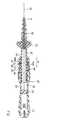
図1に示すように、本発明の一実施形態に係る先端偏向操作可能カテーテル2は、たとえば心臓における不整脈の診断または治療に用いられるものであり、カテーテルチューブ(チューブ部材)4の遠位端部に、先端チップ10と、複数の中間リング12とが装着してある。先端チップ10および中間リング12は、電極として機能し、たとえば接着剤による接着などでカテーテルチューブ4に対して接続固定される。 As shown in FIG. 1, a tip deflection operable catheter 2 according to an embodiment of the present invention is used, for example, for diagnosis or treatment of arrhythmia in the heart, and a distal end portion of a catheter tube (tube member) 4. In addition, a
カテーテルチューブ4の近位端には、ハンドル20が装着してある。カテーテルチューブ4及びハンドル20内部には、それぞれ導線が引き通されており、その先端が電極を構成する先端チップ10および中間リング12に電気的に接続されている。また、これらの導線の基端は、図2に示すハンドル20の後端部に固定してあるコネクタ21に接続される。また、ハンドル20には、カテーテルチューブ4の遠位端部の偏向移動操作(首振り操作)を行うための操作用摘み22が装着してある。 A
カテーテルチューブ4は、中空のチューブ部材で構成してあり、軸方向に沿って同じ特性のチューブで構成しても良いが、好ましくは、比較的可撓性に優れた遠位端部分と、遠位端部分に対して軸方向に一体に形成され、遠位端部分よりも比較的に剛性のある近位端部分とを有する。なお、図1では、カテーテルチューブ4の長さが短く図示してあるが、実際には、ハンドル20の軸方向長さよりも数倍〜数十倍程度に長い。 The
カテーテルチューブ4は、たとえばポリオレフィン、ポリアミド、ポリエーテルポリアミド、ポリウレタンなどの合成樹脂で構成される。カテーテルチューブ4の外径は、一般に0.6〜3mm程度であり、その内径は、0.5〜2.5mm程度である。カテーテルチューブ4の軸方向ルーメンには、図1に示す電極を構成する先端チップ10および中間リング12に接続される導線が、それぞれ絶縁されて通してある。 The
図1に示す先端チップ10および中間リング12は、たとえばアルミニウム、銅、ステンレス、金、白金など、電気伝導性の良好な金属で構成される。なお、X線に対する造影性を良好に持たせるためには、これらの先端チップ10および中間リング12は、白金などで構成されることが好ましい。先端チップ10および中間リング12の外径は、特に限定されないが、カテーテルチューブ4の外径と同程度であることが好ましく、通常、0.5〜3mm程度である。 The
カテーテルチューブ4の遠位端近傍の内部には、首振り部材が収容してある。首振り部材としては、特に限定されず、たとえば板バネなどで構成してある。この首振り部材としての板バネには、図2〜図4に示す操作用ワイヤ30の遠位端が接続固定してある。 A swinging member is accommodated in the vicinity of the distal end of the
操作用ワイヤ30の外径は、特に限定されないが、好ましくは0.01〜0.3mm、さらに好ましくは0.03〜0.08mmである。この操作用ワイヤ30は、たとえばNi−Ti系超弾性合金製で構成してあるが、必ずしも金属で構成する必要はない。操作用ワイヤ30は、たとえば高強度の非導電性ワイヤなどで構成しても良い。 The outer diameter of the
操作用ワイヤ30の近位端は、本実施形態では、操作用ワイヤ30の張力を調整した後に、図2に示すように、ワイヤ張力調整具32に固定される。ワイヤ張力調整具32は、ハンドル20のハンドル本体24の内部に軸方向移動自在に装着してある。このワイヤ張力調整具32を、ハンドル本体24の内部の所定の軸方向位置に固定することで、操作用ワイヤ30の張力を調整可能になっている。 In the present embodiment, the proximal end of the
図2に示すように、カテーテルチューブ4の近位端は、シースチューブ26を介して、操作用摘み22および中軸部分28に固定してある。操作用摘み22および中軸部分28が操作部に対応する。中軸部分28は、ハンドル本体24の内部に形成してある軸孔25の内部に挿入され、ハンドル本体24に対して軸方向移動自在になっている。 As shown in FIG. 2, the proximal end of the
操作者は、ハンドル本体24を片手でつかみ、その片手の指で、操作用摘み22を操作し、中軸部分28をハンドル本体24に対して軸方向に移動操作可能になっている。中軸部分28は、カテーテルチューブ4の近位端に接続固定してあることから、中軸部分28をハンドル本体24に対して軸方向に移動させると、操作用ワイヤ30に対してカテーテルチューブ4の近位端が軸方向に相対移動する。なお、操作用ワイヤ30の先端はカテーテルチューブ4の遠位端近傍に設けられた首振り部材に固定されており、操作用ワイヤ30の近位端はハンドル20に固定されたワイヤ張力調整具32に固定されている。 The operator can hold the
中軸部分28を遠位端側に移動させると、操作用ワイヤ30の近位端がワイヤ張力調整具32に固定されたままカテーテルチューブ4の近位端が遠位端側へ相対移動する。この場合には、当該中軸部分28の操作によって、操作用ワイヤ30にはテンションが掛かり、カテーテルチューブ4には軸方向に圧縮する力が掛かることになる。なお、操作用ワイヤ30及びカテーテルチューブ4は、ほとんど軸方向の長さが変わることがないため、カテーテルチューブ4及び操作用ワイヤ30が曲がることになる。その結果として、図1に示すように、カテーテルチューブ4の遠位端部が、矢印Aで示すように、首振り偏向動作を行う。 When the
すなわち、カテーテル2の遠位端は、図1に示すハンドル20の操作用摘み22を軸方向Xに操作することにより、A方向に偏向して曲折移動させることができる。なお、ハンドル20を軸回りに回転させれば、体腔内に挿入された状態で、カテーテル2に対するA方向の向きを自由に設定することができる。 That is, the distal end of the catheter 2 can be bent and moved in the direction A by operating the
本実施形態では、図3および図4に示すように、中軸部分28の外周面には、テーパ面40が形成してある。テーパ面40は、ハンドル本体24の遠位端側に行くほど、外径が小さくなるテーパ面である。テーパ面40の軸方向の長さは、ハンドル本体24に対して操作用摘み22が軸方向に相対移動可能な範囲長さと同等以上が好ましい。具体的には、テーパ面40の軸方向の長さは、好ましくは5〜20mmである。テーパ面40のテーパ傾斜角度は、軸芯に対して、好ましくは0.1〜2.0度の角度である。 In the present embodiment, as shown in FIGS. 3 and 4, a
テーパ面40における最大外径は、図2に示す軸孔25の内径に対して同等以下の寸法であり、中軸部分28が軸孔25の内部を軸方向Xに移動可能となるように決定される。中軸部分28の軸方向長さは、テーパ面40の軸方向長さよりも、好ましくは40〜80mm長い。 The maximum outer diameter of the tapered
ハンドル本体24の遠位端24aの外周には、雄ネジ部51が形成してあり、先端キャップ44の内周には、雌ネジ部52が形成してある。雄ネジ部51と雌ネジ部52とはネジ結合するようになっている。先端キャップ44の遠位端44aの内径は、雌ネジ部52が形成される先端キャップ44の内周の内径よりも小さい。ハンドル本体24の遠位端24aと先端キャップ44の遠位端44aとの間であって、雌ネジ部52の内周と中軸部分28の外周との間には、リング溝46が形成される。 A
リング溝46には、リング状弾性部材であるOリング42と、その軸方向の両側にバックアップリング41および43が装着される。ハンドル本体24の雄ネジ部51を先端キャップ44の雌ネジ部52にねじ込むことで、リング溝46の軸方向長さが調節され、バックアップリング41および43に挟まれたOリング42が軸方向に変形し、中軸部分28のテーパ面40に対するOリング42の締付力が変化する。 In the
図5に示すように、Oリング42の軸方向の幅t0は、好ましくは、0.5〜4mmである。また、バックアップリング41,43の軸方向の幅t1,t2は同じであってもよいし、異なっていてもよい。幅t1と幅t2を同じにすることで、バックアップリングを製造する際のコストを低減することができる。 As shown in FIG. 5, the axial width t0 of the O-
Oリング42の軸方向の幅t0は、バックアップリング41,43の軸方向の幅t1,t2以上であることが好ましい。なお、図3および図4に示すキャップ44の近位端44bとハンドル本体24との間に形成される軸方向の隙間幅t4の隙間は、バックアップリング41,43の幅t1,t2によって調整することができる。隙間幅t4が、できる限り小さくなるようにバックアップリング41,43の幅t1,t2を調整することが好ましい。 The axial width t0 of the O-
Oリング42およびバックアップリング41,43は、これらのリングに外力が作用しない状態で、同じ内径D2を有する。これらのリング41〜43に外力が作用しない状態で、内径D2は、中軸部分28のテーパ面40の最大外径D1と略等しいことが好ましいが、内径D2は最大外径D1よりも0.05〜0.1mm程度大きく構成されていてもよい。 The O-
Oリング42およびバックアップリング43の外径D4は、ハンドル本体24の遠位端24aの内径に等しい。先端キャップ44の遠位端44aに接触するバックアップリング41の外径D3は、リング溝46におけるキャップ44の内径よりも小さく、キャップ44の遠位端44aの内径D5よりも大きい。 The outer diameter D4 of the O-
なお、図5では、バックアップリング41の外径D3がバックアップリング43の外径よりも大きく描いてあるが、実際には、バックアップリング41の外径D3とバックアップリング43の外径D4とは等しいことが好ましい。このような構成とすることで、バックアップリング41,43を製造する際のコストをさらに低減することができる。 In FIG. 5, the outer diameter D3 of the
Oリング42は、たとえばシリコーンゴム、ニトリルゴム、フッ素ゴムなどのゴムまたは合成樹脂などで構成される。バックアップリング41,43は、たとえばフッ素樹脂、金属等で構成されることが好ましい。バックアップリング41,43は、Oリング42よりも摩擦抵抗が小さく(あるいは滑りやすい)、硬度が高い(あるいはヤング率が高い)ことが好ましい。 The O-
Oリング42のJIS−A硬度は、好ましくは、A30〜A70で、バックアップリング41,43の硬度は、JIS−D硬度のD40以上に硬いことが好ましい。なお、本発明でいうJIS−A硬度とは、JIS規格K−6301に準拠して計測される物性値を指す。 The JIS-A hardness of the O-
次に、本実施形態に係る先端偏向操作可能カテーテル2の使用方法について説明する。操作者は、ハンドル本体24を片手でつかみ、その片手の指で、操作用摘み22を操作し、中軸部分28をハンドル本体24に対して、たとえば図3に示す状態から図4に示す状態に操作したとする。 Next, a method of using the distal deflection operation-enabled catheter 2 according to this embodiment will be described. The operator grasps the
その場合には、中軸部分28はカテーテルチューブ4の近位端に接続固定してあることから、操作用ワイヤ30に対してカテーテルチューブ4が軸方向に相対移動する。その結果として、図1に示すように、カテーテルチューブ4の遠位端部が、直線状態から矢印Aで示すように、曲折状態になる。 In that case, since the
しかも本実施形態では、ハンドル本体24に対して中軸部分28が遠位端方向に向けて移動することで、Oリング42およびバックアップリング41,43が、当該中軸部分28に対して、テーパ面40における外径が小さい側から大きい側に軸方向に相対移動する。すなわち、この場合には、当該移動に応じてOリング42を円周方向へ広げる方向への力が増すことになる。なお、リング溝46の内径は不変であるため、当該移動に応じてリング溝46の径方向間隔が狭くなっていき、Oリング42が中軸部分28及びハンドル本体24を押し付ける力が強くなり、Oリング42と中軸部分28との摩擦力が増すことになる。 Moreover, in the present embodiment, the O-
また、ハンドル本体24に対して中軸部分28を最も近位端方向に移動させたときには、Oリング42は、中軸部分28に対して、相対的に、テーパ面40における外径がもっとも小さい位置に位置している。そのため、この場合には、中軸部分28とリング溝46との間隔が最も広くなるため、Oリング42が中軸部分28及びキャップ44を押し付ける力が最も小さくなり、Oリング42と中軸部分28との摩擦力が低減されている。したがって、操作用摘み22をハンドル本体24に対して軸方向に離れる方向に向けて移動させる移動初期時には、操作用摘み22は、軽い力で軸方向に移動する。 Further, when the
バックアップリング41,43は、Oリング42よりも摩擦抵抗が小さい部材で構成されていることから、Oリング42のテーパ面40に対する締付や軸方向移動を妨げない。また、バックアップリング41,43はOリング42よりも硬度が高い部材で構成されていることから、Oリング42とは異なり、弾性変形によるテーパ面40への締付は小さく、Oリング42のテーパ面40に対する締付や軸方向移動を妨げない。 Since the backup rings 41 and 43 are made of a member having a smaller frictional resistance than the O-
また、バックアップリング41,43は、ハンドル本体24とテーパ面40との隙間へOリング42が咬み込まれることを防止すると共に、特に、先端キャップ44の遠位端44aとテーパ面40との隙間へOリング42が咬み込まれることを防止し、移動操作不良を効果的に防ぐことができる。 Further, the backup rings 41 and 43 prevent the O-
そして、操作用摘み22から指を離したとしても、図4に示すように、外径が大きなテーパ面40にOリング42が接触するため、その摩擦力のために、操作用摘み22は、軸方向に移動しない。そのため、操作用摘み22から指を離したとしても、図1に示すカテーテルチューブ4の遠位端部は、曲がった状態を維持することができる。 Even when the finger is released from the
図1に示すカテーテルチューブ4の遠位端部を真っ直ぐな状態にするには、テーパ面40とOリング42との摩擦力に逆らって、操作用摘み22を、軸方向に移動させ、図4から図3に示す状態に戻せばよい。その際には、Oリング42は、テーパ面40における大きな外径部分から小さな外径部分に移動するため、テーパ面40とOリング42との摩擦力は、徐々に小さくなる。 In order to make the distal end of the
また、バックアップリング41,43がOリング42を締め付ける力を調整することで、カテーテル用ハンドルの操作性を調整することができる。締め付け力が大きくなると、テーパ面40とOリング42との摩擦力が大きくなり、締め付け力が小さくなると、テーパ面40とOリング42との摩擦力が小さくなる。 Further, the operability of the catheter handle can be adjusted by adjusting the force with which the backup rings 41 and 43 tighten the O-
締め付け力の調整は、ハンドル本体24の雄ネジ部51を先端キャップ44の雌ネジ部52にねじ込むことでなされ、リング溝46の軸方向長さが調節され、バックアップリング41および43に挟まれたOリング42が軸方向に変形し、中軸部分28のテーパ面40に対するOリング42の締付力が変化する。 The tightening force is adjusted by screwing the male threaded
なお、先端キャップ44の近位端44bとハンドル本体24との間には、クリック用リング50を介在させても良い。クリック用リング50は先端キャップ44を円周方向に回転させる際に、クリック感を付与する機構を備えた部材である。締め付け力の調整は、カテーテル用ハンドルの組立後、たとえば医者等の操作者に渡す前に行うこともできるし、操作者自身が調整することもできる。 A
なお、本発明は、上述した実施形態に限定されるものではなく、種々に改変することができる。たとえば、本発明に係るカテーテル用ハンドルは、図示する実施形態の先端偏向操作可能カテーテルに限らず、その他のカテーテルにも適用することができる。 The present invention is not limited to the above-described embodiment, and can be variously modified. For example, the catheter handle according to the present invention can be applied not only to the tip deflection operable catheter of the illustrated embodiment but also to other catheters.
2… 先端偏向操作可能カテーテル
4… カテーテルチューブ
20… カテーテル用ハンドル
22… 操作用摘み
24… ハンドル本体
30… 操作用ワイヤ
40… テーパ面
42… Oリング
41、43… バックアップリングDESCRIPTION OF SYMBOLS 2 ... Tip deflection operation
Claims (5)
Translated fromJapanese前記ハンドル本体に対して軸方向に移動自在に装着される操作部と、
前記ハンドル本体と前記操作部との間に装着されるリング状の弾性部材と、
前記弾性部材を前記ハンドル本体の軸方向両側からはさんで装着されるバックアップリングとを有し、
前記操作部にカテーテルチューブの近位端が固定してあり、
前記ハンドル本体に前記弾性部材およびバックアップリングが装着してあり、
前記ハンドル本体の内周に前記操作部を構成する中軸部分が入り込み、
前記ハンドル本体の内周に入り込んでいる前記中軸部分の外周面には、遠位端方向に外径が小さくなるテーパ面が形成してあり、
前記テーパ面の外周面に、前記弾性部材の内周面と前記バックアップリングの内周面とが接触して軸方向に移動可能に構成してあり、
前記カテーテルチューブ内には、操作用ワイヤが挿通してあり、
前記操作用ワイヤの遠位端が前記カテーテルチューブの遠位端の一部に固定してあり、
前記操作用ワイヤの近位端が前記ハンドル本体の一部に固定してあり、
前記ハンドル本体に対して前記操作部を近位端から遠位端方向に向けて移動することで、前記カテーテルチューブの遠位端部が曲折するとともに、前記弾性部材が、前記テーパ面における外径が大きい側に軸方向に相対移動することを特徴とするカテーテル用ハンドル。The handle body,
An operation unit that is mounted so as to be movable in the axial direction with respect to the handle body;
A ring-shaped elastic member mounted between the handle body and the operation unit;
A backup ring that is mounted on both sides of the elastic member from both axial sides of the handle body;
The proximal end of the catheter tube is fixed to the operation part,
The elastic member and the backup ring are attached to the handle body,
A middle shaft portion constituting the operation unit enters the inner periphery of the handle body,
On the outer peripheral surface of the middle shaft portion entering the inner periphery of the handle body, a tapered surface having a smaller outer diameter in the distal end direction is formed.
The inner peripheral surface of the elastic member and the inner peripheral surface of the backup ring are in contact with the outer peripheral surface of the tapered surface, and are configured to be movable in the axial direction.
In the catheter tube, an operation wire is inserted,
The distal end of the manipulation wire is secured to a portion of the distal end of the catheter tube;
A proximal end of the operating wire is fixed to a part of the handle body;
The distal end portion of the catheter tube is bent by moving the operating portion from the proximal end toward the distal end relative to the handle body, and the elastic member has an outer diameter at the tapered surface. The catheter handleis characterized in that it moves relative to the larger side in the axial direction .
Priority Applications (6)
| Application Number | Priority Date | Filing Date | Title |
|---|---|---|---|
| JP2008132514AJP4224122B1 (en) | 2008-05-20 | 2008-05-20 | Catheter handle |
| PCT/JP2009/058749WO2009142120A1 (en) | 2008-05-20 | 2009-05-11 | Catheter handle |
| AU2009250619AAU2009250619B2 (en) | 2008-05-20 | 2009-05-11 | Catheter handle |
| KR1020090041103AKR100926640B1 (en) | 2008-05-20 | 2009-05-12 | Catheter handle |
| CN2009102038638ACN101584905B (en) | 2008-05-20 | 2009-05-20 | catheter handle |
| HK10102889.8AHK1137674B (en) | 2008-05-20 | 2010-03-19 | Handle for catheters |
Applications Claiming Priority (1)
| Application Number | Priority Date | Filing Date | Title |
|---|---|---|---|
| JP2008132514AJP4224122B1 (en) | 2008-05-20 | 2008-05-20 | Catheter handle |
Publications (2)
| Publication Number | Publication Date |
|---|---|
| JP4224122B1true JP4224122B1 (en) | 2009-02-12 |
| JP2011055847A JP2011055847A (en) | 2011-03-24 |
Family
ID=40403899
Family Applications (1)
| Application Number | Title | Priority Date | Filing Date |
|---|---|---|---|
| JP2008132514AActiveJP4224122B1 (en) | 2008-05-20 | 2008-05-20 | Catheter handle |
Country Status (3)
| Country | Link |
|---|---|
| JP (1) | JP4224122B1 (en) |
| KR (1) | KR100926640B1 (en) |
| CN (1) | CN101584905B (en) |
Cited By (1)
| Publication number | Priority date | Publication date | Assignee | Title |
|---|---|---|---|---|
| EP2569040B1 (en)* | 2010-05-11 | 2019-02-06 | Cathrx Ltd | A catheter handle |
Families Citing this family (3)
| Publication number | Priority date | Publication date | Assignee | Title |
|---|---|---|---|---|
| US9050010B2 (en) | 2012-12-31 | 2015-06-09 | Biosense Webster (Israel) Ltd. | Double loop lasso with single puller wire for bi-directional actuation |
| EP3062861B1 (en)* | 2013-12-20 | 2018-03-21 | St. Jude Medical, Cardiology Division, Inc. | Actuator restraining assembly for medical device |
| US11471650B2 (en) | 2019-09-20 | 2022-10-18 | Biosense Webster (Israel) Ltd. | Mechanism for manipulating a puller wire |
Family Cites Families (3)
| Publication number | Priority date | Publication date | Assignee | Title |
|---|---|---|---|---|
| US6120476A (en)* | 1997-12-01 | 2000-09-19 | Cordis Webster, Inc. | Irrigated tip catheter |
| US6795721B2 (en)* | 2000-01-27 | 2004-09-21 | Biosense Webster, Inc. | Bidirectional catheter having mapping assembly |
| DE60020175T2 (en)* | 2000-12-22 | 2006-01-26 | Wilson-Cook Medical Inc. | CLOSING ADAPTER FOR CATHETER |
- 2008
- 2008-05-20JPJP2008132514Apatent/JP4224122B1/enactiveActive
- 2009
- 2009-05-12KRKR1020090041103Apatent/KR100926640B1/ennot_activeExpired - Fee Related
- 2009-05-20CNCN2009102038638Apatent/CN101584905B/ennot_activeExpired - Fee Related
Cited By (1)
| Publication number | Priority date | Publication date | Assignee | Title |
|---|---|---|---|---|
| EP2569040B1 (en)* | 2010-05-11 | 2019-02-06 | Cathrx Ltd | A catheter handle |
Also Published As
| Publication number | Publication date |
|---|---|
| CN101584905A (en) | 2009-11-25 |
| HK1137674A1 (en) | 2010-08-06 |
| CN101584905B (en) | 2012-10-17 |
| KR100926640B1 (en) | 2009-11-13 |
| JP2011055847A (en) | 2011-03-24 |
Similar Documents
| Publication | Publication Date | Title |
|---|---|---|
| JP4173531B1 (en) | Catheter handle | |
| JP4027411B1 (en) | Electrode catheter | |
| JP4526585B2 (en) | Tip deflectable catheter | |
| JP4224122B1 (en) | Catheter handle | |
| JP4368410B1 (en) | Catheter handle | |
| JP4224123B1 (en) | Catheter handle | |
| WO2013140889A1 (en) | Catheter handle | |
| WO2009142120A1 (en) | Catheter handle | |
| JP5429878B2 (en) | Catheter handle | |
| JP5360804B2 (en) | Catheter handle | |
| JP2008521496A (en) | Improvement of sphincterotome | |
| JP4441509B2 (en) | Endoscopic treatment tool | |
| JP6071852B2 (en) | Tip deflectable catheter | |
| JP5787394B2 (en) | Tip deflectable catheter | |
| JP4236206B1 (en) | Electrode catheter | |
| HK1137674B (en) | Handle for catheters | |
| HK1137673B (en) | Handle for catheters | |
| JP2014144223A (en) | Catheter with deflectable tip | |
| HK1137675B (en) | Handle for catheters |
Legal Events
| Date | Code | Title | Description |
|---|---|---|---|
| TRDD | Decision of grant or rejection written | ||
| A01 | Written decision to grant a patent or to grant a registration (utility model) | Free format text:JAPANESE INTERMEDIATE CODE: A01 Effective date:20081106 | |
| A01 | Written decision to grant a patent or to grant a registration (utility model) | Free format text:JAPANESE INTERMEDIATE CODE: A01 | |
| A61 | First payment of annual fees (during grant procedure) | Free format text:JAPANESE INTERMEDIATE CODE: A61 Effective date:20081120 | |
| R150 | Certificate of patent or registration of utility model | Ref document number:4224122 Country of ref document:JP Free format text:JAPANESE INTERMEDIATE CODE: R150 Free format text:JAPANESE INTERMEDIATE CODE: R150 | |
| FPAY | Renewal fee payment (event date is renewal date of database) | Free format text:PAYMENT UNTIL: 20111128 Year of fee payment:3 | |
| FPAY | Renewal fee payment (event date is renewal date of database) | Free format text:PAYMENT UNTIL: 20111128 Year of fee payment:3 | |
| FPAY | Renewal fee payment (event date is renewal date of database) | Free format text:PAYMENT UNTIL: 20121128 Year of fee payment:4 | |
| R250 | Receipt of annual fees | Free format text:JAPANESE INTERMEDIATE CODE: R250 | |
| FPAY | Renewal fee payment (event date is renewal date of database) | Free format text:PAYMENT UNTIL: 20131128 Year of fee payment:5 | |
| R250 | Receipt of annual fees | Free format text:JAPANESE INTERMEDIATE CODE: R250 | |
| R250 | Receipt of annual fees | Free format text:JAPANESE INTERMEDIATE CODE: R250 | |
| R250 | Receipt of annual fees | Free format text:JAPANESE INTERMEDIATE CODE: R250 | |
| R250 | Receipt of annual fees | Free format text:JAPANESE INTERMEDIATE CODE: R250 | |
| R250 | Receipt of annual fees | Free format text:JAPANESE INTERMEDIATE CODE: R250 | |
| R250 | Receipt of annual fees | Free format text:JAPANESE INTERMEDIATE CODE: R250 | |
| R250 | Receipt of annual fees | Free format text:JAPANESE INTERMEDIATE CODE: R250 | |
| R250 | Receipt of annual fees | Free format text:JAPANESE INTERMEDIATE CODE: R250 | |
| R250 | Receipt of annual fees | Free format text:JAPANESE INTERMEDIATE CODE: R250 | |
| R250 | Receipt of annual fees | Free format text:JAPANESE INTERMEDIATE CODE: R250 | |
| S802 | Written request for registration of partial abandonment of right | Free format text:JAPANESE INTERMEDIATE CODE: R311802 | |
| R350 | Written notification of registration of transfer | Free format text:JAPANESE INTERMEDIATE CODE: R350 | |
| R250 | Receipt of annual fees | Free format text:JAPANESE INTERMEDIATE CODE: R250 | |
| S802 | Written request for registration of partial abandonment of right | Free format text:JAPANESE INTERMEDIATE CODE: R311802 | |
| R360 | Written notification for declining of transfer of rights | Free format text:JAPANESE INTERMEDIATE CODE: R360 | |
| R250 | Receipt of annual fees | Free format text:JAPANESE INTERMEDIATE CODE: R250 | |
| R370 | Written measure of declining of transfer procedure | Free format text:JAPANESE INTERMEDIATE CODE: R370 | |
| R250 | Receipt of annual fees | Free format text:JAPANESE INTERMEDIATE CODE: R250 |