JP4220184B2 - Cap seal with IC tag - Google Patents
Cap seal with IC tagDownload PDFInfo
- Publication number
- JP4220184B2 JP4220184B2JP2002173840AJP2002173840AJP4220184B2JP 4220184 B2JP4220184 B2JP 4220184B2JP 2002173840 AJP2002173840 AJP 2002173840AJP 2002173840 AJP2002173840 AJP 2002173840AJP 4220184 B2JP4220184 B2JP 4220184B2
- Authority
- JP
- Japan
- Prior art keywords
- tag
- contact
- top sheet
- antenna pattern
- cap seal
- Prior art date
- Legal status (The legal status is an assumption and is not a legal conclusion. Google has not performed a legal analysis and makes no representation as to the accuracy of the status listed.)
- Expired - Fee Related
Links
Images


Landscapes
- Packages (AREA)
- Closures For Containers (AREA)
- Credit Cards Or The Like (AREA)
- Details Of Rigid Or Semi-Rigid Containers (AREA)
Description
Translated fromJapanese【0001】
【発明の属する技術分野】
この発明は、非接触ICタグ付きキャップシールに関する。
詳しくは、ボトルや樽のように天面に注出入口を有する容器の当該注出入口に被着するキャップシールに、アンテナパターンを印刷すると共に、非接触ICタグを貼着して商品の品質情報や履歴の管理に使用しようとするものである。
従って、本発明の利用分野は食品や飲料の製造や流通、あるいはラベルの製造等に関連する分野である。
【0002】
【従来技術】
従来、容器やビール樽等の管理は、ラベル面に印刷または印字されている文字等の情報や、一次元バーコードや二次元バーコード等に基づいて行われているが情報量が十分でないことが指摘されていた。
また、バーコードは、リーダーによる個別の読み取りや接触あるいは近接読み取りが必要であることから、読み取りに手間がかかり作業効率が低下する問題も指摘されている。
さらに、ビールや発泡酒の樽等には、情報を書き込むスペースがなく、内容表示や流通経路、保管条件、消費期限などの各情報は多くが記載されていないのが実情である。また、バーコード等に記録して流通過程においた場合は、バーコードや印字等したラベル自体が破損して読み取りが困難になる問題がある。
【0003】
一方、近年、非接触ICタグ(一般に、「非接触データキャリア」、「無線ICタグ」、「非接触IC」、「非接触ICラベル」、「RFIDタグ」等と表現される場合もある。)に情報を記録して、物流や商品の品質または履歴を管理することが行われるようになってきている。
しかし、非接触ICタグを容器やビール樽に利用する先行技術はあまりみられない。特開平11−73219、特開平11−73221、特開平11−73461号公報には、非接触方式データキャリアをビア樽に使用することが記載されているが、非接触ICタグを装着する具体的内容は記載されていない。
また、データキャリアをキャップシールの形態にすることなどは全く記載されていないので、適切な装着方法を行わなければ、非接触ICタグが流通過程において紛失することも考えられる。
【0004】
【発明が解決しようとする課題】
そこで、本発明では非接触ICタグを、キャップシールの形態にしてボトルやビア樽等に保持させることを着想し、その実現態様について検討し、本発明の完成に至ったものである。
【0005】
【課題を解決するための手段】
上記課題を解決するための本発明の要旨の第1は、天面に内容物の注出入口を有する容器に被着され、天面シートと側面樹脂シュリンクフィルムから構成されるキャップシールにおいて、前記天面シートの内面側に、導電性インキからなるアンテナパターンが印刷され、その内面のアンテナパターンに対応する位置の外面側に非接触ICタグラベルがアンテナパターンと静電結合する状態で貼着されていることを特徴とするICタグ付きキャップシール、にある。
【0006】
上記課題を解決するための本発明の要旨の第2は、ビールや発泡酒用樽の注出入口部に被着され、天面シートと側面樹脂シュリンクフィルムから構成されるキャップシールにおいて、前記天面シート内面側に、導電性インキからなるアンテナパターンが印刷され、その内面のアンテナパターンに対応する位置の外面側に非接触ICタグラベルがアンテナパターンと静電結合する状態で貼着されていることを特徴とするICタグ付きキャップシール、にある。
【0008】
上記において、天面シートの基材を、紙、合成紙又はポリエステル、ポリエチレン、ポリプロピレン、ポリアミド、ポリスチレンから選ばれた熱可塑性樹脂とすることができ、天面シートの基材の厚みを、100μmを超え〜500μm未満とし、側面樹脂シュリンクフィルムの膜厚を、20μm〜100μm、とすれば、非接触ICタグ付きキャップシールとして好適に使用できる。
【0009】
【発明の実施の形態】
本発明のICタグ付きキャップシールは、天面に注出入口を有する一般容器やビールまたは発泡酒用樽の注出入口部に被着して使用するもので、製品の情報管理や販売管理、品質、使用期限管理を容易にしようとするものである。
キャップシールの用途目的は、上記の態様に分類できるが、キャップシールの実施形態については、以下のように分類できる。
キャップシールの形態について、図面を参照して説明する。
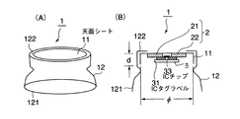
図1は、キャップシールの第1の参考例形態、図2は、第2の参考例形態、図3は、本発明の実施形態を示す。いずれも、(A)は斜視図、(B)は、断面図を示している。図4は、第1の参考例形態の天面シート平面図である。
【0010】
図1、図2、図3のように、キャップシール1は、天面シート11と側面樹脂シュリンクフィルム12とから構成されている。
天面シート11は、アピール部分ともいわれるが、容器のキャップ頭頂部の大きさに相当する平面部111と、頭頂部から周縁に沿って下降する側部落ち込み部112からなる。平面部111にはアンテナパターン2が印刷されていて、当該アンテナパターン印刷部に非接触ICタグラベル3が貼着されている。
図示していないが、天面シートにアンテナパターン以外の絵柄印刷をするのは自由である。
【0011】
非接触ICタグラベル3は、アンテナパターンに接触して貼着される場合だけではなく、アンテナパターンに対応する位置部分であるが、アンテナパターンとは反対側の面にICタグラベル3を貼着する場合も含まれる。
アンテナパターンと非接触ICタグラベルが直接接触していなくても、数百μm以内の間隔で離れるのであれば、オーミックコンタクトによりアンテナの機能をすることが認められているからである。
【0012】
樹脂シュリンクフィルム12は、前記落ち込み部112の外側を囲うように成形された円環状スカート部材であって、容器等に装着後に再度熱条件を付与することにより、収縮して容器のキャップ周囲部分に固着させることができる。
側部落ち込み部112の径は、下方側が拡張するようなテーパー形状にされていることが容器やビア樽への装着を容易にすることから好ましい。
また、シュリンクフィルム12は、あらかじめ天面シートの周縁を覆って脱落を防止するように、外周の立ち上がり部121から直角に曲がったつば部分122を有するように成形されている。
【0013】
図1のように、キャップシール1の第1の実施形態では、天面シート11の外面側平面部(表面側)に、アンテナパターン21,22が導電性インキにより印刷され、当該アンテナパターン印刷面に接するように非接触ICタグラベル3が貼着されている。
【0014】
図2のように、キャップシール1の第2の実施形態では、天面シート11の内面側平面部(裏面側)に、アンテナパターン21,22が導電性インキにより印刷され、当該アンテナパターン印刷面に接するように非接触ICタグラベル3が貼着されている。非接触ICタグラベル3背面に金属製キャップ等があっても非接触交信に影響を与えることはない。
その他の構成は、第1の実施形態と同様である。
【0015】
図3のように、キャップシール1の第3の実施形態では、天面シート11の内面側平面部(裏面側)に、アンテナパターン21,22が導電性インキにより印刷されているが、非接触ICタグラベル3は、天面シートを介した外面であって、当該アンテナパターンに対応する位置に貼着されている。
【0016】
第1、第2、第3の実施形態のキャップシールのいずれも使用方法は同様であるが、第2の実施形態では、ICタグラベル3が天面シート1と容器のキャップ間に保持されるので、ICタグラベル3が剥離して紛失するようなことは少なくなる。反対に、第1や第3の実施形態では、ICタグラベルが表面に表れているので、リーダライタの読み取り動作がし易く確実性が高まる。
第2、第3の実施形態では、天面シートの表面にアンテナパターン以外の絵柄を設ける場合には適している。もっとも、アンテナパターンを導電性インキで印刷した上に、非導電性の通常の絵柄印刷を重ねて印刷することも自由であるから、第1の実施形態であっても絵柄印刷が妨げられることはない。
【0017】
図4は、第1の実施形態での天面シート平面図である。表面には導電性インキで印刷された左右のパターン21,22からなるアンテナパターン2が表れている。
印刷するアンテナパターン2は、ほぼ任意の形状であって良いが、非接触ICタグラベル3のICチップ33の2つの端子(パッド)に直接的または間接的に接続する静電結合型パターンに印刷する。従って、図示のように羽状に開いた左右のパターン21,22に限らず、2本の直線状パターンや2つの円形、矩形状パターン等であってもよい。左右非対象のパターンであっても勿論構わない。
【0018】
ICタグラベル3は、正しくは「ICチップ実装ラベル」を意味する。
このものは、図5のように、小型のアンテナパターン321,322を印刷したラベル基材31に、ICチップ33をアンテナパターン321,322と導通するうよに装着したラベルのことである。
アンテナパターン321,322も導電性のインキで印刷されており、双方のパターンの接近する位置で、当該アンテナパターンとICチップ33のパッド間が導通するよう異方導電性接着剤等により装着されている。
一般に、モトローラ社が製造する「Bistatix」(商標)のようにタック加工されたラベル状のものが使用される。サイズは、16mm×16mm程度にされている。
【0019】
このICタグラベル3のアンテナパターン321,322がキャップシール1に印刷したアンテナパターン21,22に、それぞれのパターンが接するように貼着され、ICチップのパッドとアンテナパターン21,22間が、電気的に導通していることが好ましいが、直接電気的に導通していなくても、静電結合的に結合(オーミックコンタクト)してアンテナの機能を果たすので、多少、位置ずれしていても、非接触通信機能を確保することはできる。
多少というのは、アンテナパターン321と21、322と22の相互間が近接位置関係にある場合であり、例えば、アンテナパターン321と322に最も近接するラベルのアンテナパターンが共にパターン22であるような場合は、短絡することになり正常には機能しない。
また、フィルム基材を介して貼着しても、アンテナパターン間の位置が対応し、かつ、フィルムの厚みが数百μmの範囲内であれば、オーミックコンタクトにより通信機能を果たすことができる。
【0020】
図6は、第1の実施形態でキャップシールを容器に装着した状態を示している。この実施形態では、非接触ICタグラベル3が容器のキャップ部101の表面に表れているので、リーダライタ5による読み取り動作を確実に行うことができる。ボトル容器の大きさや形状、アンテナパターンの大きさ、リーダライタの出力等によって変化するが、リーダライタから数センチから数十センチ以内にある容器やビア樽の複数のICタグラベルを同時に読み取りすることもできるので、読み取り作業負担を軽減することもできる。
【0021】
非接触ICタグラベルの交信周波数としては、一般的には125kHz、13.56MHz、2.45GHz、5.8GHz(マイクロ波)の周波数帯から選択して使用される。非接触ICタグラベルでは、13.56MHzを利用する場合が多く、各種のリーダやリーダライタが使用されている。
リーダライタは、スキャナともいわれ、呼出し信号に対する応答波を検出して非接触ICタグの読み取りをする。
【0022】
ICチップ33は、シリコン基板に集積回路やメモリを形成したもので、ICタグラベル用としては、2mm×2mm以内の大きさで、厚み0.5mm以内にしたものが使用されている。
ICメモリの場合は、1024ビットで、128文字の記録ができ通常の包装体として最低限の情報記録に適用できる。数キロビットであれば、二次元バーコード以上の記録が可能であり、出荷後に書き込み消去が自由にできる利点を有する。
【0023】
<その他の材質に関する実施形態>
(1)天面シート
本発明に使用する天面シートの基材は、食品等に影響を与えず、また廃棄処分により環境に負荷を与えないものが好ましい。一般的には、紙、合成紙又はポリエステル、ポリエチレン、ポリプロピレン、ポリアミド、ポリスチレンが好ましく使用され、その厚みは、100μm〜500μm程度が好ましい。100μm以下では平面性が維持できない場合があり、500μm以上では、アンテナパターンと非接触ICタグラベルを天面シートを介して装着した場合に、オーミックコンタクトが得られない場合があるからである。
紙の場合は、絶縁性確保の点から耐水処理をして使用することが好ましい。
(2)シュリンクフィルム
本発明に使用するシュリンクフィルムは、天面シートと同質の材料を使用するが、紙ではシュリンク性は得られない。一般に延伸した樹脂フィルムが使用される。その厚みは、20μm〜100μmの範囲が保護被覆としての強度もあり、また熱収縮も容易な範囲として推奨できる。
【0024】
(3)アンテナ印刷用インキ
本発明に使用するアンテナ印刷用インキは、オフセット、グラビア、シルクスクリーン印刷用の導電性インキを使用することができる。
導電性インキは、カーボンや黒鉛、あるいは銀粉やアルミ粉、あるいはこれらの混合体をビヒクルに分散したインキを使用できる。さらには、酸化すず、酸化チタン粉末等を使用した透明導電性インキであってもよい。
【0025】
【実施例】
図1〜図4を参照して本発明の実施例および参考例を説明する。
(実施例)
厚み100μmのPETシート(東レ株式会社製「ルミラー」)を真空圧空成形し、天面シート11の側部落ち込み部の高さdが、6.5mmであって、直径φが、71.5mmのシート成形品を作製した。
その天面シートの内面側となる面に導電性インキからなるアンテナパターン21,22をグラビア印刷した。左右のアンテナパターンが近接する位置であって、天面シート11を介する外面側に非接触ICタグラベル(モトローラ社製「ICチップ実装ラベル(Bistatix)」)3を、ICチップ側が、アンテナ印刷面に面するように貼着した(図3)。
【0026】
その後、筒状加工したシュリンクフィルム12を巻付け、所定の形状金型から熱風、および水蒸気により熱収縮加工し、図3のような特殊形状の、非接触ICタグラベル付きキャップシール1を作製した。
非接触ICタグラベル3に対して、所定のデータを記録させた後、ICタグリーダ(モトローラ社製Bistatixリーダ「WAVE」)を用いて、情報の読み取り書き込み試験を行ったところいずれも支障なく、読み取り書き込みできることが確認された。
【0027】
(参考例1)
厚み300μmのポリスチレンシート(太洋化成株式会社製「W−20」)をシート成形し(真空圧空成形)、天面シート11の側部落ち込み部dが、6.5mmであって、直径φが、71.5mmのシート成形品を作製した。
その天面シートの容器のキャップ部に装着した場合に内面側となる面へ導電性インキからなるアンテナパターン21,22をグラビア印刷し、左右のアンテナパターンが近接する位置であって、双方のアンテナパターン21,22に接する位置に、非接触ICタグラベル(モトローラ社製「ICチップ実装ラベル(Bistatix)(商標)」)3を、ICチップ側が、アンテナ印刷面に面するように貼着した(図2)。
【0028】
その後、天面シート成形品へ、厚み80μmの横一軸延伸ポリスチレンフィルム(グンゼ株式会社製「ファンシーラップGMA」)を筒状加工したシュリンクフィルム12を巻付け、所定の形状金型から熱風、および水蒸気により熱収縮加工し、前記図2のような特殊形状の、非接触ICタグラベル付きキャップシール1を作製した。
【0029】
このキャップシール1を、生ビール用アルミ樽(20リットル容器)のキャップ部分へ、手で装着し、380°Cの熱風を斜め上方から当てたところ、側面シュリンクフィルム12が樽のキャップ形状に密着するように収縮し、優れた外観のキャップ保護包装体が得られた。
非接触ICタグラベル3に対して、所定のデータを記録させた後、ICタグリーダ(モトローラ社製Bistatixリーダ「WAVE」)を用いて、情報の読み取り書き込み試験を行ったところいずれも支障なく、読み取り書き込みできることが確認された。
【0030】
(参考例2)
厚み300μmのポリスチレンシート(太洋化成株式会社製「W−20」)をシート成形し、天面シート11の側部落ち込み部の高さdが、6.5mmであって、直径φが、71.5mmのシート成形品を作製した。
その天面シートの外面側表面に導電性インキからなるアンテナパターン21,22をグラビア印刷し、左右のアンテナパターンが近接する位置であって、双方のアンテナパターン21,22に接する位置に、非接触ICタグラベル(モトローラ社製「ICチップ実装ラベル(Bistatix)」)3を、ICチップ側が、アンテナ印刷面に面するように貼着した(図1)。
【0031】
その後、参考例1と同様にして、筒状加工したシュリンクフィルム12を巻付け、所定の形状金型から熱風、および水蒸気により熱収縮加工し、前記図1のような特殊形状の、非接触ICタグラベル付きキャップシール1を作製した。
非接触ICタグラベル3に対して、所定のデータを記録させた後、ICタグリーダ(モトローラ社製Bistatixリーダ「WAVE」)を用いて、情報の読み取り書き込み試験を行ったところいずれも支障なく、読み取り書き込みできることが確認された。
【0032】
(参考例3)
厚み500μmのポリプロピレン樹脂系合成紙シート(ユポ・コーポレーション製「WPF−500」)を成形し、天面シート11の側部落ち込み部の高さdが、6.5mmであって、直径φが71.5mmのシート成形品を作製した。
その天面シートの内面側となる面に導電性インキからなるアンテナパターン21,22をグラビア印刷し、左右のアンテナパターンが近接する位置であって、双方のアンテナパターン21,22に接する位置に、非接触ICタグラベル(モトローラ社製「ICチップ実装ラベル(Bistatix)」)3を、ICチップ側が、アンテナ印刷面に面するように貼着した(図2)。
【0033】
その後、参考例1と同様にして、筒状加工したシュリンクフィルム12を巻付け、所定の形状金型から熱風、および水蒸気により熱収縮加工し、前記図2のような特殊形状の、非接触ICタグラベル付きキャップシール1を作製した。
非接触ICタグラベル3に対して、所定のデータを記録させた後、ICタグリーダ(モトローラ社製Bistatixリーダ「WAVE」)を用いて、情報の読み取り書き込み試験を行ったところいずれも支障なく、読み取り書き込みできることが確認された。
【0034】
(参考例4)
厚み300μmのポリスチレンシート(太洋化成株式会社製「W−20」)を真空圧空成形し、天面シート11の側部落ち込み部の高さdが、6.5mmであって、リブ(凹部)により補強されている、直径φが71.5mmのシート成形品を作製した。
その天面シートの内面側下面に導電性インキからなるアンテナパターン21,22をグラビア印刷し、左右のアンテナパターンが近接する位置であって、双方のアンテナパターン21,22に接する位置に、非接触ICタグラベル(モトローラ社製「ICチップ実装ラベル(Bistatix)」)3を、ICチップ側が、アンテナ印刷面に面するように貼着した(図2)。
【0035】
その後、参考例1と同様にして、筒状加工したシュリンクフィルム12を巻付け、所定の形状金型から熱風、および水蒸気により熱収縮加工し、前記図2のような特殊形状の、非接触ICタグラベル付きキャップシール1を作製した。
非接触ICタグラベル3に対して、所定のデータを記録させた後、ICタグリーダ(モトローラ社製Bistatixリーダ「WAVE」)を用いて、情報の読み取り書き込み試験を行ったところいずれも支障なく、読み取り書き込みできることが確認された。
【0036】
【発明の効果】
上述のように、本発明のキャップシールは、天面シートにアンテナパターンが印刷され、それに非接触ICタグラベルが貼着されているので、非接触通信機能を有し、リーダライタと交信してキャップシールに必要な情報を不足なく記録しまた読み取りすることができる。
本発明のキャップシールは、ビールや発泡酒、炭酸系酒類、原液シロップ、炭酸清涼飲料類等が充填される樽の注出口キャップ部分に装着して、各製品の流通管理、製品情報表示、販売管理等に好適に使用できる。
【図面の簡単な説明】
【図1】キャップシールの第1の参考例形態を示す図である。
【図2】同第2の参考例形態を示す図である。
【図3】本発明の実施形態を示す図である。
【図4】第1の参考例形態の天面シート平面図である。
【図5】ICタグラベルの構成を示す断面図である。
【図6】第1の参考例形態でキャップシールを容器に装着した状態を示す図である。
【符号の説明】
1 キャップシール
2 アンテナパターン
3 非接触ICタグラベル
5 リーダライタ
10 容器
11 ラベル基材、基材フィルム
21,22 アンテナパターン
33 ICチップ[0001]
BACKGROUND OF THE INVENTION
The present invention relates to a cap seal with a non-contact IC tag.
Specifically, the antenna pattern is printed on the cap seal attached to the pouring inlet of the container having the pouring inlet on the top surface such as a bottle or a barrel, and a non-contact IC tag is attached to the product quality information or It is intended to be used for history management.
Therefore, the field of use of the present invention is a field related to the manufacture and distribution of foods and beverages or the manufacture of labels.
[0002]
[Prior art]
Conventionally, management of containers and beer barrels has been performed based on information such as characters printed or printed on the label surface, one-dimensional barcodes, two-dimensional barcodes, etc., but the amount of information is not sufficient Was pointed out.
In addition, since barcodes require individual reading, contact, or proximity reading by a reader, it has been pointed out that reading is troublesome and the work efficiency is reduced.
Furthermore, there is no space for writing information in a barrel of beer or sparkling liquor, and the fact is that there are not many information such as content display, distribution channels, storage conditions, and expiration dates. In addition, when recorded on a bar code or the like and in the distribution process, there is a problem that the bar code or printed label itself is damaged and reading becomes difficult.
[0003]
On the other hand, in recent years, non-contact IC tags (generally, “non-contact data carrier”, “wireless IC tag”, “non-contact IC”, “non-contact IC label”, “RFID tag”, etc. may be expressed. ) To record the information and manage the logistics or product quality or history.
However, there are few prior arts that use non-contact IC tags for containers and beer barrels. JP-A-11-73219, JP-A-11-73221, and JP-A-11-73461 describe using a non-contact type data carrier for a via barrel, but a specific example of mounting a non-contact IC tag. The contents are not described.
In addition, since it is not described at all that the data carrier is in the form of a cap seal, the non-contact IC tag may be lost in the distribution process unless an appropriate mounting method is performed.
[0004]
[Problems to be solved by the invention]
In view of this, the present invention has been conceived in which a non-contact IC tag is held in a bottle, a via barrel, or the like in the form of a cap seal, and an implementation mode thereof has been studied, and the present invention has been completed.
[0005]
[Means for Solving the Problems]
A first aspect of the present invention for solving the above-described problems is a cap seal that is attached to a container having a content inlet on the top surface and includes a top surface sheet and a side resin shrink film. An antenna pattern made of conductive ink is printed on theinner surface side of the face sheet, and a non-contact IC tag label is stuck onthe outer surface side ofthe position corresponding to the antenna pattern on theinner surface ina state of being electrostatically coupled to the antenna pattern . A cap seal with an IC tag, characterized in that.
[0006]
The second of the gist of the present invention for solving the above problems is a cap seal that is attached to a pouring inlet of a barrel for beer or sparkling liquor and is composed of a top sheet and a side resin shrink film. An antenna pattern made of conductive ink is printed on theinner surface side of the sheet, and a non-contact IC tag label is stuck onthe outer surface side ofthe position corresponding to the antenna pattern on theinner surface ina state of being electrostatically coupled to the antenna pattern. It is in the cap seal with an IC tag that is characterized.
[0008]
In the above, the base materialof the top sheet can be a paper, synthetic paper or a thermoplastic resin selected from polyester, polyethylene, polypropylene, polyamide, polystyrene, and the thickness of the base material of the top sheet is 100 μm. If it is over tolessthan 500μm and the film thickness of the side resin shrink film is from 20 μm to 100 μm, it can be suitably used as a cap seal with a non-contact IC tag.
[0009]
DETAILED DESCRIPTION OF THE INVENTION
The cap seal with an IC tag of the present invention is used by adhering it to a general container having a pouring inlet on the top surface or a pouring inlet part of a barrel for beer or sparkling liquor. Product information management and sales management, quality, It is intended to facilitate the expiration date management.
The application purpose of the cap seal can be classified into the above aspects, but the embodiment of the cap seal can be classified as follows.
The form of thekey Yappushiru will be described with reference to the drawings.
1, the firstreference example forms ofkey Yappushiru, 2, the secondreference example embodiment, FIG. 3 shows animplementation formof the present invention. In both cases, (A) is a perspective view, and (B) is a cross-sectional view. FIG. 4 is a plan view of the top sheet of the firstreference embodiment.
[0010]
1, 2, as shown in FIG.3, key Yappushiru 1 is composed of a
Although the
Although not shown, it is free to print a pattern other than the antenna pattern on the top sheet.
[0011]
The non-contact
This is because even if the antenna pattern and the non-contact IC tag label are not in direct contact with each other, if the antenna pattern and the non-contact IC tag label are separated by an interval of several hundreds μm, it is permitted to function as an antenna by ohmic contact.
[0012]
The
The diameter of the
Further, the
[0013]
As shown in FIG. 1, in the first embodiment of the
[0014]
As shown in FIG. 2, in the second embodiment of the
Other configurations are the same as those of the first embodiment.
[0015]
As shown in FIG. 3, in the third embodiment of the
[0016]
The cap seals of the first, second, and third embodiments are used in the same manner, but in the second embodiment, the
The second and third embodiments are suitable when a pattern other than the antenna pattern is provided on the surface of the top sheet. However, since it is also possible to print the antenna pattern with conductive ink and to superimpose non-conductive normal pattern printing, it is possible to prevent pattern printing even in the first embodiment. Absent.
[0017]
FIG. 4 is a top view of the top sheet in the first embodiment. On the surface, an
The
[0018]
The
This is a label in which an
The
In general, a label-like label that is tacked like “Bistatix” (trademark) manufactured by Motorola is used. The size is about 16 mm × 16 mm.
[0019]
The
Somewhat is the case where the
Moreover, even if it sticks through a film base material, if the position between antenna patterns respond | corresponds and the thickness of a film is in the range of several hundred micrometers, a communication function can be achieved by ohmic contact.
[0020]
FIG. 6 shows a state in which the cap seal is attached to the container in the first embodiment. In this embodiment, since the non-contact
[0021]
In general, the communication frequency of the non-contact IC tag label is selected from a frequency band of 125 kHz, 13.56 MHz, 2.45 GHz, and 5.8 GHz (microwave). Non-contact IC tag labels often use 13.56 MHz, and various readers and reader / writers are used.
The reader / writer is also called a scanner, and reads a non-contact IC tag by detecting a response wave to a call signal.
[0022]
The
In the case of an IC memory, 128 characters can be recorded with 1024 bits and can be applied to minimum information recording as a normal package. If it is several kilobits, it is possible to record more than a two-dimensional barcode, and there is an advantage that writing and erasing can be freely performed after shipment.
[0023]
<Embodiments related to other materials>
(1) Top sheet The base material of the top sheet used in the present invention is preferably one that does not affect foods or the like and that does not affect the environment due to disposal. In general, paper, synthetic paper or polyester, polyethylene, polypropylene, polyamide and polystyrene are preferably used, and the thickness is preferably about 100 μm to 500 μm. If the thickness is 100 μm or less, the planarity may not be maintained. If the thickness is 500 μm or more, ohmic contact may not be obtained when the antenna pattern and the non-contact IC tag label are mounted via the top sheet.
In the case of paper, it is preferable to use it after water-resistant treatment from the viewpoint of ensuring insulation.
(2) Shrink film The shrink film used in the present invention uses the same material as that of the top sheet, but the paper does not provide a shrink property. In general, a stretched resin film is used. The thickness of 20 μm to 100 μm has a strength as a protective coating, and heat shrinkage can be recommended as an easy range.
[0024]
(3) Ink for antenna printing As the ink for antenna printing used in the present invention, conductive ink for offset, gravure and silk screen printing can be used.
As the conductive ink, ink in which carbon, graphite, silver powder, aluminum powder, or a mixture thereof is dispersed in a vehicle can be used. Further, it may be a transparent conductive ink using tin oxide, titanium oxide powder or the like.
[0025]
【Example】
Examplesand reference examples of the present inventionwill be described withreference to FIGS.
(Example)
A 100 μm-thick PET sheet (“Lumirror” manufactured by Toray Industries, Inc.) is vacuum-compressed and the height d of the side depression of the
The
[0026]
Then, the shrink-processed
After recording predetermined data on the non-contact
[0027]
(Reference Example 1 )
A 300 μm-thick polystyrene sheet (“W-20” manufactured by Taiyo Kasei Co., Ltd.) is formed into a sheet (vacuum and pressure forming), the side depression d of the
When mounted on the cap of the container of the top sheet, the
[0028]
Thereafter, a
[0029]
When this
After recording predetermined data on the non-contact
[0030]
(Reference Example 2)
A polystyrene sheet having a thickness of 300 μm (“W-20” manufactured by Taiyo Kasei Co., Ltd.) is formed into a sheet. The height d of the side depression of the
The
[0031]
Thereafter, in the same manner as inReference Example 1, a cylindrically processed
After recording predetermined data on the non-contact
[0032]
(Reference Example 3)
A polypropylene resin synthetic paper sheet having a thickness of 500 μm (“WPF-500” manufactured by YUPO Corporation) is formed, the height d of the side portion of the
The
[0033]
Thereafter, in the same manner as inReference Example 1, a cylindrically processed
After recording predetermined data on the non-contact
[0034]
(Reference Example4 )
A 300-μm-thick polystyrene sheet (“W-20” manufactured by Taiyo Kasei Co., Ltd.) is vacuum-compressed and the height d of the side depression of the
The
[0035]
Thereafter, in the same manner as inReference Example 1, a cylindrically processed
After recording predetermined data on the non-contact
[0036]
【The invention's effect】
As described above, the cap seal of the present invention has a non-contact IC tag label printed on an antenna pattern on the top sheet, and has a non-contact communication function. Information necessary for the seal can be recorded and read without a shortage.
The cap seal of the present invention is attached to the outlet cap portion of a barrel filled with beer, sparkling liquor, carbonated liquor, undiluted syrup, carbonated soft drinks, etc., distribution management of each product, product information display, sales It can be suitably used for management.
[Brief description of the drawings]
1 is a diagram showing a firstreference example embodiment of thekey Yappushiru.
FIG. 2 is a diagram showing a secondreference example form;
FIG. 3 is a diagram showing an embodiment of thepresent invention .
FIG. 4 is a plan view of the top sheet of the firstreference embodiment.
FIG. 5 is a cross-sectional view showing a configuration of an IC tag label.
6 is a diagram showing a state of mounting the cap seal with the container in the firstreference example embodiment.
[Explanation of symbols]
DESCRIPTION OF
Claims (6)
Translated fromJapanesePriority Applications (1)
| Application Number | Priority Date | Filing Date | Title |
|---|---|---|---|
| JP2002173840AJP4220184B2 (en) | 2002-06-14 | 2002-06-14 | Cap seal with IC tag |
Applications Claiming Priority (1)
| Application Number | Priority Date | Filing Date | Title |
|---|---|---|---|
| JP2002173840AJP4220184B2 (en) | 2002-06-14 | 2002-06-14 | Cap seal with IC tag |
Publications (2)
| Publication Number | Publication Date |
|---|---|
| JP2004018003A JP2004018003A (en) | 2004-01-22 |
| JP4220184B2true JP4220184B2 (en) | 2009-02-04 |
Family
ID=31172961
Family Applications (1)
| Application Number | Title | Priority Date | Filing Date |
|---|---|---|---|
| JP2002173840AExpired - Fee RelatedJP4220184B2 (en) | 2002-06-14 | 2002-06-14 | Cap seal with IC tag |
Country Status (1)
| Country | Link |
|---|---|
| JP (1) | JP4220184B2 (en) |
Cited By (1)
| Publication number | Priority date | Publication date | Assignee | Title |
|---|---|---|---|---|
| WO2014129485A1 (en) | 2013-02-19 | 2014-08-28 | 凸版印刷株式会社 | Container |
Families Citing this family (19)
| Publication number | Priority date | Publication date | Assignee | Title |
|---|---|---|---|---|
| KR101149633B1 (en) | 2004-08-09 | 2012-05-25 | 산코루 가부시키가이샤 | Seal with ic tag and method of attaching the same |
| KR100615387B1 (en) | 2004-08-25 | 2006-08-31 | 최정곤 | Container lid with wireless tag |
| JP2006123917A (en)* | 2004-10-26 | 2006-05-18 | Mitsubishi Materials Corp | Sealing structure, unsealing determination method, and tag |
| JP4532259B2 (en)* | 2004-12-24 | 2010-08-25 | 麒麟麦酒株式会社 | Manufacturing method of lid with information code |
| WO2007065196A1 (en)* | 2005-12-06 | 2007-06-14 | Magellan Technology Pty Ltd | A vessel closure |
| JP2007168883A (en)* | 2005-12-26 | 2007-07-05 | Toppan Printing Co Ltd | IC tag for liquid bottle and liquid bottle container equipped with IC tag |
| JP5124960B2 (en)* | 2006-03-09 | 2013-01-23 | 東洋製罐株式会社 | Metal lid with metal tag and metal container |
| CN101948025B (en) | 2006-02-22 | 2012-05-30 | 东洋制罐株式会社 | Metal cover with RFID tag and metal article |
| US7432817B2 (en)* | 2006-03-23 | 2008-10-07 | Xerox Corporation | Module with RFID tag and associated bridge antenna |
| JP4849975B2 (en)* | 2006-06-28 | 2012-01-11 | 三光合成株式会社 | Sample storage container |
| JP4840918B2 (en)* | 2006-07-12 | 2011-12-21 | 日本クラウンコルク株式会社 | Cover with IC tag |
| JP4840917B2 (en)* | 2006-07-12 | 2011-12-21 | 日本クラウンコルク株式会社 | Cover with IC tag |
| JP4942440B2 (en)* | 2006-09-29 | 2012-05-30 | 東洋製罐株式会社 | Cap with IC tag |
| JP5063406B2 (en)* | 2007-03-22 | 2012-10-31 | 東洋製罐株式会社 | Plastic cap with IC tag |
| JP4954818B2 (en)* | 2007-07-19 | 2012-06-20 | 三光合成株式会社 | Sample storage container and blood collection container |
| JP5063426B2 (en)* | 2007-11-06 | 2012-10-31 | 東洋製罐株式会社 | Attaching the IC tag to the cap |
| US9031425B2 (en)* | 2013-03-15 | 2015-05-12 | Xerox Corporation | Customer replaceable unit monitor positioning apparatus |
| CN110088010B (en)* | 2016-12-15 | 2020-10-27 | 凸版印刷株式会社 | Cap seal |
| JP2018188199A (en)* | 2017-05-09 | 2018-11-29 | 凸版印刷株式会社 | Container for goods with IC tag |
- 2002
- 2002-06-14JPJP2002173840Apatent/JP4220184B2/ennot_activeExpired - Fee Related
Cited By (2)
| Publication number | Priority date | Publication date | Assignee | Title |
|---|---|---|---|---|
| WO2014129485A1 (en) | 2013-02-19 | 2014-08-28 | 凸版印刷株式会社 | Container |
| US9617038B2 (en) | 2013-02-19 | 2017-04-11 | Toppan Printing Co., Ltd. | Container including an inlet having an IC chip and an antenna for monitoring tamper events of the container |
Also Published As
| Publication number | Publication date |
|---|---|
| JP2004018003A (en) | 2004-01-22 |
Similar Documents
| Publication | Publication Date | Title |
|---|---|---|
| JP4220184B2 (en) | Cap seal with IC tag | |
| KR101149633B1 (en) | Seal with ic tag and method of attaching the same | |
| JP4170680B2 (en) | Label for bottle with IC tag | |
| JP4712986B2 (en) | Liquid container with RFID tag | |
| US7212127B2 (en) | RFID tag and label | |
| US7975414B2 (en) | Label comprising a transponder and a system comprising a transponder | |
| KR20020042854A (en) | Package Printing System with RFID Write/Read Capability | |
| US11537836B2 (en) | Merchandise attachment with RFID transponder | |
| JP2002308437A (en) | Inspection system using RFID tag | |
| KR20070049105A (en) | How to attach a label with RFID tag on an article | |
| AU2014203313A1 (en) | A modular radio frequency identification tagging method | |
| JP2006277524A (en) | RFID label and its attaching method | |
| JP4532259B2 (en) | Manufacturing method of lid with information code | |
| JP2006003497A (en) | Label with ic tag and container with ic tag | |
| US8490882B2 (en) | Apparatus and process including radio frequency identification devices | |
| JP2002207984A (en) | Label printing system and printer | |
| JP4580530B2 (en) | Chemical package with non-contact data carrier | |
| US12223380B2 (en) | Multi-purpose RFID label | |
| JP4627583B2 (en) | Laminated label | |
| CN214175130U (en) | Dual-purpose label | |
| JP6962065B2 (en) | RFID tag label | |
| KR200301036Y1 (en) | RF-ID Tag Case with easy reuse and detachment | |
| JPH06139421A (en) | Certifying and identifying card and its production | |
| JP2003006598A (en) | Label with non-contact IC chip | |
| KR200326636Y1 (en) | Radio frequency identification tag |
Legal Events
| Date | Code | Title | Description |
|---|---|---|---|
| A621 | Written request for application examination | Free format text:JAPANESE INTERMEDIATE CODE: A621 Effective date:20050608 | |
| A131 | Notification of reasons for refusal | Free format text:JAPANESE INTERMEDIATE CODE: A131 Effective date:20080723 | |
| A521 | Written amendment | Free format text:JAPANESE INTERMEDIATE CODE: A523 Effective date:20080917 | |
| TRDD | Decision of grant or rejection written | ||
| A01 | Written decision to grant a patent or to grant a registration (utility model) | Free format text:JAPANESE INTERMEDIATE CODE: A01 Effective date:20081104 | |
| A01 | Written decision to grant a patent or to grant a registration (utility model) | Free format text:JAPANESE INTERMEDIATE CODE: A01 | |
| A61 | First payment of annual fees (during grant procedure) | Free format text:JAPANESE INTERMEDIATE CODE: A61 Effective date:20081113 | |
| FPAY | Renewal fee payment (event date is renewal date of database) | Free format text:PAYMENT UNTIL: 20111121 Year of fee payment:3 | |
| R150 | Certificate of patent or registration of utility model | Ref document number:4220184 Country of ref document:JP Free format text:JAPANESE INTERMEDIATE CODE: R150 Free format text:JAPANESE INTERMEDIATE CODE: R150 | |
| FPAY | Renewal fee payment (event date is renewal date of database) | Free format text:PAYMENT UNTIL: 20121121 Year of fee payment:4 | |
| FPAY | Renewal fee payment (event date is renewal date of database) | Free format text:PAYMENT UNTIL: 20131121 Year of fee payment:5 | |
| LAPS | Cancellation because of no payment of annual fees |