JP4220023B2 - Thermoforming equipment for plastic containers - Google Patents
Thermoforming equipment for plastic containersDownload PDFInfo
- Publication number
- JP4220023B2 JP4220023B2JP21972198AJP21972198AJP4220023B2JP 4220023 B2JP4220023 B2JP 4220023B2JP 21972198 AJP21972198 AJP 21972198AJP 21972198 AJP21972198 AJP 21972198AJP 4220023 B2JP4220023 B2JP 4220023B2
- Authority
- JP
- Japan
- Prior art keywords
- blank
- heating
- container
- thermoforming
- plastic
- Prior art date
- Legal status (The legal status is an assumption and is not a legal conclusion. Google has not performed a legal analysis and makes no representation as to the accuracy of the status listed.)
- Expired - Fee Related
Links
Images


Classifications
- B—PERFORMING OPERATIONS; TRANSPORTING
- B29—WORKING OF PLASTICS; WORKING OF SUBSTANCES IN A PLASTIC STATE IN GENERAL
- B29C—SHAPING OR JOINING OF PLASTICS; SHAPING OF MATERIAL IN A PLASTIC STATE, NOT OTHERWISE PROVIDED FOR; AFTER-TREATMENT OF THE SHAPED PRODUCTS, e.g. REPAIRING
- B29C51/00—Shaping by thermoforming, i.e. shaping sheets or sheet like preforms after heating, e.g. shaping sheets in matched moulds or by deep-drawing; Apparatus therefor
- B29C51/18—Thermoforming apparatus
- B29C51/20—Thermoforming apparatus having movable moulds or mould parts
- B29C51/24—Thermoforming apparatus having movable moulds or mould parts mounted on movable endless supports
- B—PERFORMING OPERATIONS; TRANSPORTING
- B29—WORKING OF PLASTICS; WORKING OF SUBSTANCES IN A PLASTIC STATE IN GENERAL
- B29C—SHAPING OR JOINING OF PLASTICS; SHAPING OF MATERIAL IN A PLASTIC STATE, NOT OTHERWISE PROVIDED FOR; AFTER-TREATMENT OF THE SHAPED PRODUCTS, e.g. REPAIRING
- B29C51/00—Shaping by thermoforming, i.e. shaping sheets or sheet like preforms after heating, e.g. shaping sheets in matched moulds or by deep-drawing; Apparatus therefor
- B29C51/04—Combined thermoforming and prestretching, e.g. biaxial stretching
- B29C51/06—Combined thermoforming and prestretching, e.g. biaxial stretching using pressure difference for prestretching
- B—PERFORMING OPERATIONS; TRANSPORTING
- B29—WORKING OF PLASTICS; WORKING OF SUBSTANCES IN A PLASTIC STATE IN GENERAL
- B29C—SHAPING OR JOINING OF PLASTICS; SHAPING OF MATERIAL IN A PLASTIC STATE, NOT OTHERWISE PROVIDED FOR; AFTER-TREATMENT OF THE SHAPED PRODUCTS, e.g. REPAIRING
- B29C51/00—Shaping by thermoforming, i.e. shaping sheets or sheet like preforms after heating, e.g. shaping sheets in matched moulds or by deep-drawing; Apparatus therefor
- B29C51/08—Deep drawing or matched-mould forming, i.e. using mechanical means only
- B—PERFORMING OPERATIONS; TRANSPORTING
- B29—WORKING OF PLASTICS; WORKING OF SUBSTANCES IN A PLASTIC STATE IN GENERAL
- B29C—SHAPING OR JOINING OF PLASTICS; SHAPING OF MATERIAL IN A PLASTIC STATE, NOT OTHERWISE PROVIDED FOR; AFTER-TREATMENT OF THE SHAPED PRODUCTS, e.g. REPAIRING
- B29C51/00—Shaping by thermoforming, i.e. shaping sheets or sheet like preforms after heating, e.g. shaping sheets in matched moulds or by deep-drawing; Apparatus therefor
- B29C51/10—Forming by pressure difference, e.g. vacuum
- B—PERFORMING OPERATIONS; TRANSPORTING
- B29—WORKING OF PLASTICS; WORKING OF SUBSTANCES IN A PLASTIC STATE IN GENERAL
- B29C—SHAPING OR JOINING OF PLASTICS; SHAPING OF MATERIAL IN A PLASTIC STATE, NOT OTHERWISE PROVIDED FOR; AFTER-TREATMENT OF THE SHAPED PRODUCTS, e.g. REPAIRING
- B29C51/00—Shaping by thermoforming, i.e. shaping sheets or sheet like preforms after heating, e.g. shaping sheets in matched moulds or by deep-drawing; Apparatus therefor
- B29C51/26—Component parts, details or accessories; Auxiliary operations
- B29C51/261—Handling means, e.g. transfer means, feeding means
- B—PERFORMING OPERATIONS; TRANSPORTING
- B29—WORKING OF PLASTICS; WORKING OF SUBSTANCES IN A PLASTIC STATE IN GENERAL
- B29C—SHAPING OR JOINING OF PLASTICS; SHAPING OF MATERIAL IN A PLASTIC STATE, NOT OTHERWISE PROVIDED FOR; AFTER-TREATMENT OF THE SHAPED PRODUCTS, e.g. REPAIRING
- B29C51/00—Shaping by thermoforming, i.e. shaping sheets or sheet like preforms after heating, e.g. shaping sheets in matched moulds or by deep-drawing; Apparatus therefor
- B29C51/26—Component parts, details or accessories; Auxiliary operations
- B29C51/42—Heating or cooling
- B29C51/421—Heating or cooling of preforms, specially adapted for thermoforming
- B—PERFORMING OPERATIONS; TRANSPORTING
- B29—WORKING OF PLASTICS; WORKING OF SUBSTANCES IN A PLASTIC STATE IN GENERAL
- B29D—PRODUCING PARTICULAR ARTICLES FROM PLASTICS OR FROM SUBSTANCES IN A PLASTIC STATE
- B29D22/00—Producing hollow articles
- B29D22/003—Containers for packaging, storing or transporting, e.g. bottles, jars, cans, barrels, tanks
Landscapes
- Engineering & Computer Science (AREA)
- Mechanical Engineering (AREA)
- Blow-Moulding Or Thermoforming Of Plastics Or The Like (AREA)
Description
Translated fromJapanese【0001】
【発明の属する技術分野】
本発明はフランジを有するプラスチック容器の熱成形装置に関し、特にポリプロピレン、ポリエチレン、ポリエチレンテレフタレート、ポリ塩化ビニル等の熱可塑性プラスチックシートから容器を熱成形する装置に関する。
【0002】
【従来の技術】
従来より、プラスチック片から容器を製造する技術が各種提案されている。たとえば、四角形に切断されたプラスチックシート片を円形ディスク状に鋳造し、これを容器に加圧成形する方法が、特開昭47−4588号公報に記載されている。この方法はスクラップレス成形(SFP)と呼ばれ、実際に使用されている技術である。しかしながら、この技術は四角形のプラスチックシート片から円形ディスクを鋳造するものであるため、円形ディスク内にひずみが残り、また多層系のシートを用いた場合は均一な層構成を保持したまま円形ディスクを得ることが困難であり、さらには鋳造および加圧成形のために複雑且つ大型の装置を必要とし、生産性が悪く、汎用性に欠けるものであった。
【0003】
その他にもプラスチック片より円形ディスクを鋳造した後に該円形ディスクを容器成形する多くの技術が提案されているが、いずれも上記と概ね同様の問題を有する。
【0004】
また、特公昭48−11817号公報には、特殊形状のプラスチックブランクから均一な肉厚を有する容器を得る冷間成形方法が記載されているが、これもブランクの製造が困難であると共に、多層系シートブランクには不向きな技術である。
【0005】
また、特開昭47−8089号公報には、プラスチックブランクを加熱プレート間で連続的に接触するよう維持しながら加熱する方法が提案されているが、この技術によると、平行に設置された加熱プレート間をプラスチックブランクが滑りながら搬送加熱されるものであり、プレートの温度やプラスチックブランク表面の滑り性に少しでも狂いが生ずるとブランクが変形してしまい、実用化には至っていない。
【0006】
特公平6−88328号公報および特開平2−150338号公報には、プラスチックブランクの外縁部を固相域に維持固定し、中心部の成形領域のみを溶融相に加熱して、レトルタブル容器を成形する技術が提案されている。しかしながら、この技術はブランクを該プラスチックの融点以上の温度を有するオーブン内に所定時間入れておくことにより加熱するいわゆる間接加熱方式を採用しているため、ブランクの外縁部を固相域に維持するために特別な手段を採用しなければならず、コスト面での不利を避けられない。また、オーブン内に長時間保持されるブランクは成形領域の全体が高温に加熱されるため、熱伝導により外縁部も膨張変化しようとする傾向が強くなり、これを抑制するためには冷却手段を併用しなければならないという新たな問題も派生していた。
【0007】
【発明が解決しようとする課題】
本発明は、これら従来技術の不利欠点を解消し、プラスチックブランクから容器を効率的に製造することを課題としている。
【0008】
(削除)
【0009】
【課題を解決するための手段】
すなわち、請求項1に係る本発明によるプラスチック容器の熱成形装置は、熱可塑性プラスチックシートから打ち抜かれたプラスチックブランクを用いてプラスチック容器を熱成形する装置であって、ブランク外縁部を支持するフランジ支持部を有することによりブランクを保持するブランク保持手段と、ブランク保持手段を所定の搬送路に沿って所定の方向に搬送する搬送手段と、搬送路上の所定のブランク供給位置においてブランク保持手段にブランクを供給するブランク供給手段と、搬送路においてブランク供給位置より搬送方向前方に設けられるブランク加熱位置においてブランク保持手段のフランジ支持部に支持されるブランク外縁部よりも内側の成形領域に両面より熱盤を当てて直接加熱によりプラスチック熱成形可能な所定の温度に加熱する加熱手段と、搬送路においてブランク加熱位置より搬送方向前方に設けられる容器成形位置においてブランク外縁部を上下より挟持固定しながら加熱手段により加熱された成形領域を所定の容器形状に成形する成形手段と、を有してなり、ブランク保持手段は、基板に形成される複数の開口にそれぞれ嵌着固定されるリング部材と、該リング部材におけるフランジ支持部に向けて出没可能なブランク固定部材と、ブランク固定部材をフランジ支持部内に突出させる方向に付勢する付勢手段とを有してなることを特徴とする。
【0010】
(削除)
【0011】
請求項2は、請求項1のプラスチック容器の熱成形装置において、ブランク保持手段を加熱手段および/または成形手段に対して所定位置にセンタリングする位置決め手段を有することを特徴とする。
【0012】
請求項3は、請求項2のプラスチック容器の熱成形装置において、位置決め手段が、ブランク保持手段の所定箇所に固定されるシリンダと、ブランク保持手段が加熱手段および/または成形手段に対して所定位置にセンタリングされたときに該シリンダに挿入嵌合されるように加熱手段および/または成形手段に設けられるセンタリングプラグとを有してなることを特徴とする。
【0013】
請求項4は、請求項1ないし3のいずれかのプラスチック容器の熱成形装置において、搬送手段はブランク保持手段を少なくともブランク供給位置、ブランク加熱位置および容器成形位置にそれぞれ所定時間停止させた後次の停止位置に向けて所定の搬送路上を前進させることを特徴とする。
【0014】
請求項5は、請求項1ないし4のいずれかのプラスチック容器の熱成形装置において、加熱手段が、ブランク保持手段の搬送路の両側に対向配置される一対の熱盤と、これら一対の熱盤を近接する方向および離隔する方向に移動する移動手段とを有してなり、ブランク保持手段がブランク加熱位置に停止しているときに、移動手段により近接移動された一対の熱盤がブランク保持手段に保持されるブランクの両面に圧接することを特徴とする。
【0015】
請求項6は、請求項1ないし5のいずれかのプラスチック容器の熱成形装置において、加熱手段における一対の熱盤のうちの一方はブランク加熱位置においてブランク保持手段に保持されたブランクの一面の成形領域とのみ接触し、他方の熱盤はこれよりも大径であって該ブランクの他面の成形領域を超えてブランク外縁部の少なくとも一部とも接触することを特徴とする。
【0016】
請求項7は、請求項1ないし6のいずれかのプラスチック容器の熱成形装置において、加熱手段における一対の熱盤の少なくとも一方に、加熱後にブランク面にエアを吹き付けて熱盤から離すために用いられるエア噴出孔が貫通形成されることを特徴とする。
【0017】
請求項8は、請求項1ないし7のいずれかのプラスチック容器の熱成形装置において、加熱手段が搬送路に沿って複数設けられ、ブランクを順次高温に加熱することを特徴とする。
【0018】
また、請求項9に係る本発明によるプラスチック容器の熱成形装置は、熱可塑性プラスチックシートから打ち抜かれたプラスチックブランクを用いてプラスチック容器を熱成形する装置であって、ブランク外縁部を支持するフランジ支持部を有することによりブランクを保持するブランク保持手段と、ブランク保持手段を所定の搬送路に沿って所定の方向に搬送する搬送手段と、搬送路上の所定のブランク供給位置においてブランク保持手段にブランクを供給するブランク供給手段と、搬送路においてブランク供給位置より搬送方向前方に設けられるブランク加熱位置においてブランク保持手段のフランジ支持部に支持されるブランク外縁部よりも内側の成形領域に両面より熱盤を当てて直接加熱によりプラスチック熱成形可能な所定の温度に加熱する加熱手段と、搬送路においてブランク加熱位置より搬送方向前方に設けられる容器成形位置においてブランク外縁部を上下より挟持固定しながら加熱手段により加熱された成形領域を所定の容器形状に成形する成形手段と、を有してなり、成形手段が、ブランク保持手段の搬送路の一方の側に該搬送路に対して近接移動可能に配置され、製造しようとする容器本体の外形を規定する金型と、該搬送路の他方の側に該搬送路に対して近接移動可能に配置される略筒状のクランプと、金型とクランプとを互いに近接する方向に移動してそれらの間に気密空間を形成するための気密空間形成手段と、金型とクランプとの間に気密空間が形成されたときに該気密空間内のブランクを金型に圧接させるための圧接手段とを有してなることを特徴とする。
【0019】
請求項10は、請求項9のプラスチック容器の熱成形装置において、圧接手段が、クランプ内に該クランプに対して相対移動可能に設けられるプラグよりなることを特徴とする。
【0020】
請求項11は、請求項9または10のプラスチック容器の熱成形装置において、圧接手段が、成形時にブランクに向けてクランプ内に圧縮空気を導入する圧空導入手段および/または成形時にブランクの反対側より金型キャビティを真空吸引する真空吸引手段を備えることを特徴とする。
【0021】
請求項12は、請求項9ないし11のいずれかのプラスチック容器の熱成形装置において、気密空間形成手段が、クランプの下面に設けられてクランプが金型に対して近接移動したときにブランク保持手段の上面に弾性的に係合可能なパッキングを備えることを特徴とする。
【0022】
請求項13は、請求項9ないし12のいずれかのプラスチック容器の熱成形装置において、成形手段が、加熱手段により加熱された成形領域の外周部分において表面側を凸とする凹凸形状を容器フランジに賦形するための凹凸賦形手段をさらに備えることを特徴とする。
【0023】
請求項14は、請求項1ないし13のいずれかのプラスチック容器の熱成形装置において、ブランク外縁部と成形領域との境界部分に全周に亘るノッチを容器内面側から所定の深さに形成するためのノッチ形成手段をさらに備えることを特徴とする。
【0024】
請求項15は、請求項14のプラスチック容器の熱成形装置において、ノッチ形成手段がブランク供給位置とブランク加熱位置との間、ブランク加熱位置と容器成形位置との間または容器成形位置より搬送方向前方の少なくともいずれか一に設けられることを特徴とする。
【0025】
請求項16は、請求項14のプラスチック容器の熱成形装置において、ノッチ形成手段が、加熱手段における上方の熱盤の周囲に設けられて該熱盤と同期して昇降するノッチ刃または該熱盤に一体化されたノッチ刃よりなることを特徴とする。
【0026】
請求項17は、請求項14のプラスチック容器の熱成形装置において、ノッチ形成手段が、クランプの下端に一体に設けられたリング状のノッチ刃よりなることを特徴とする。
【0027】
請求項18は、請求項16または17のプラスチック容器の熱成形装置において、ノッチ刃が温度制御可能であることを特徴とする。
【0028】
本発明は、任意のプラスチックシートから効率的にプラスチック容器を熱成形可能とするものであり、該プラスチックシーとしては、ポリプロピレン、ポリエチレン等のポリオレフィン系樹脂、ポリスチレン系樹脂、ポリアミド系樹脂、ポリエステル系樹脂あるいはこれらの混合物、熱可塑性エラストマー、これらに各種の添加剤または無機充填剤を5〜70重量%を混合した樹脂、さらには、エチレンビニルアルコール共重合体、ポリ塩化ビニル、ポリ塩化ビニリデン等のガスバリア性を有する樹脂やこれらに無機充填剤を10〜80重量%を混合したもの等の任意の熱可塑性樹脂材料の、単層もしくは多層系のプラスチックシートを用いることができる。
【0029】
【発明の実施の形態】
以下添付図面に基づいて本発明の一実施例によるプラスチック容器成形装置について説明する。この成形装置は、図5に示されるようなPP(ポリプロピレン)製の食品容器1を連続的に製造する装置として構成されている。
【0030】
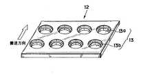
図1を参照して、PPシートから最終製品となる容器の外径に対応して打ち抜かれた円形平板状のブランクがシュータ11に供給される。本実施例において、ブランクを保持するブランクホルダ12は、搬送方向に2列、横方向に4個のブランクを載置可能とされており、これに対応して4つのシュータ11が横方向に並設されている。
【0031】
本実施例のブランクホルダ12の構成が図2に示されており、スチールやステンレス等の金属板に上記のように合計8個のブランク保持部13(搬送方向前方の列の4つのブランク保持部13aおよび搬送方向後方の列の4つのブランク保持部13b)が設けられている。各ブランク保持部13には、加熱工程においては下方熱盤19b(図6)を、また成形工程においては最終製品となる容器1の本体部2の外形を規定する金型21(図8)を、それぞれ挿入可能とするための挿入部14aがステンレス板を貫通して形成されており、その上方には、容器のフランジ3に相当する部分を載置収容するフランジ支持部14bが挿入部14aよりも大径に形成されている(図3)。
【0032】
ブランクホルダ12は、駆動制御機構(図示せず)により駆動制御されるチェーンコンベア等のコンベア15と共に、図1において反時計方向に間欠的に周回駆動される。コンベア15には多数のブランクホルダ12が隣接するもの同士略密接して、あるいは互いの間に若干の間隔を配して、任意の連結手段により連結されている。なお、図1においてブランクホルダ12は下記するブランク供給位置にあるもの(12’)、および後述する容器取り出し位置にあるもの(12’’)の2つが示され、残余は図示省略されている。
【0033】
シュータ11の下方位置に到達したブランクホルダ12(12’)は該位置にて所定時間停止し、その間にシュータ11よりブランクが供給される。このときの供給手段の具体的構成は本発明において限定的ではないが、本実施例においては図1に示されるような吸着装置16が用いられている。吸着装置16は図1に示される位置で吸引カップ16aを伸張させてシュータ11先端のブランクを吸着した後、軸16bで図示時計方向に回転して直下のブランクホルダ12の搬送方向前方の列におけるブランク保持部13aに吸引カップ16aで吸着したブランクを圧力開放により離脱して収容せしめ、この作業をもう一度繰り返して、同一ブランクホルダ12の搬送方向後方の列におけるブランク保持部13bにもブランクを供給するように構成されている。
【0034】
シュータ11から供給された未加熱のブランク10はPPシートから打ち抜かれた円形の平板状を保持しているため、容器のフランジに相当する外縁部がフランジ支持部14bに載置された状態でブランク保持部13に収容されている(図4参照)。なお、ブランク10は次の加熱工程において熱伝導により若干膨張変形するので、フランジ支持部14b(すなわち最終製品の容器フランジ3の外径)よりも若干小径に形成することが好ましく(図4参照)、これにより加熱時に熱膨張したブランク10の外縁をフランジ支持部14bの内壁に密接させることができる。
【0035】
ブランク保持部13に各々ブランク10を収容するブランクホルダ12は、コンベア15により駆動されて、加熱装置18によりブランク10を最終製品の容器形状に成形可能な所定の温度に加熱する加熱工程に投入される。加熱装置18は略同一構造のものをブランクホルダ搬送方向に複数台(本実施例では3台)設置し、これら加熱装置18により徐々に加熱温度を上昇させるものとして、ブランクに応力ひずみを与えないように構成することが好ましい。たとえば、3連の加熱装置18の熱盤温度をそれぞれ120℃、140℃および160℃に設定して、ブランク10を徐々に加熱する。
【0036】
加熱工程におけるブランク10の加熱温度は、製造しようとする食品容器の用途、すなわちその容器に収容される内容物によって異なり、ゼリー等の容器ではPPの溶融点である165℃よりも低い温度、たとえば上記のように160℃に設定することができる。炊飯した米を入れる場合(いわゆるパック入り米飯用の容器を製造する場合)には、封入後に130℃あるいはそれ以上の高温で加熱殺菌した場合にも容器が変形しないようにするために、少なくとも最終熱盤温度をPPの溶融点165℃よりも高い温度に設定して、成形後容器内に残留する成形ひずみを極力排除することが好ましい。
【0037】
各加熱装置18は、図6に示されるように、所定温度に加熱される上下熱盤19a,19bおよびこれら熱盤を各々昇降移動させる昇降機構(図示せず)を有してなる。前記ブランク供給位置でブランク供給を受けたブランクホルダ12がコンベア15駆動により前進して最初の加熱装置18a(第1加熱位置)に到達すると、該位置で所定時間停止し、それまでブランクホルダ12の搬送面から後退していた上下熱盤19a,19bが昇降機構により駆動されて、第1加熱位置に停止しているブランクホルダ12のブランク保持部13に保持されているブランク10の上下面に所定時間密着する。図6には、上下熱盤19a,19bがブランク10の上下面を圧接する作動位置が実線で示され、退避位置が仮想線で示されている。
【0038】
第1加熱位置でのブランク加熱が終了すると、上下熱盤19a,19bが退避位置に後退し、コンベア15と共にブランクホルダ12が第2の加熱装置18b(第2加熱位置)まで前進して該位置で所定時間停止して、上記と同様にして第2の加熱装置18bによるブランク加熱が行われ、次いで同様にして第3の加熱装置18cによるブランク加熱が行われる。
【0039】
前述のように、容器フランジ3に対応するブランク10の外縁部10bはブランク保持部13のフランジ支持部14bに載置されており、容器本体2に成形されるブランク10中央の成形部10aのみが加熱装置18の上下熱盤19a,19b間で、該熱盤温度に応じた温度に加熱される。すなわち、ブランク成形部10aは第1ないし第3の加熱装置18a〜18cにより徐々に加熱されるが、ゼリー容器のように融点に満たない温度に加熱する場合は、前述のように最も高い熱盤温度を有する第3の加熱装置18cでも160℃程度の熱盤温度に設定されるため、ブランク外縁部10bはもとより、熱盤により直接加熱されるブランク成形部10aもPP溶融点には到達せず、熱成形可能な程度に軟化はするが固相域に維持される。一方、パック入り米飯用の容器のように内容物充填後に高温加熱殺菌が要求される場合は、成形領域である中心部が熱盤による直接加熱を受けて融点以上に加熱される。この場合、ブランク外縁部10bも熱伝導により溶融相に変化するか、あるいは固相域に維持される。
【0040】
なお、ブランク外縁部10bが固相域に維持される場合であってもある程度の温度まで加熱されないと、成形後の容器1のフランジ3に波打ち現象が発生するおそれがあるため、図6に示されるように、下方の熱盤19bはブランク成形部19aのみに当たる径寸法とし、上方の熱盤19aはこれよりも大きくブランク外縁部10bにも当たる径寸法とすることが好ましい。上方熱盤19aについては場合によってはブランクの前面領域に当たるような径寸法としてもよい。
【0041】
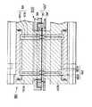
加熱工程を経たブランクホルダ12は、コンベア15により駆動されて、成形装置20により加熱されたブランク成形部10aを容器本体形状に成形する成形工程に搬送される。図7および図8に示されるように、本実施例の成形装置20は、容器本体2の外形を規定するキャビティ21aを有する金型21と、キャビティ21aと共働して成形部10aを容器本体2形状に成形するプラグ22と、プラグ22を収容するクランプ23と、金型を昇降させる第1の昇降機構(図示せず)と、プラグ22およびクランプ23を一体的および別個に昇降させる第2の昇降機構(図示せず)とを備えて構成されている。クランプ23の外径はブランク保持部13のフランジ支持部14bの内径と略同一である。クランプ23には、成形時に圧縮空気(たとえば1〜8kg/cm2)をクランプ内に導入するための圧空導入口24が設けられている。また、金型21に設けられる真空吸引口25は真空吸引源(図示せず)に接続され、成形時にキャビティ21a内を真空吸引可能としている。
【0042】
このような成形装置20が図7に示す位置にあるときに、加熱工程を経たブランク10を収容するブランクホルダ12が、下方に退避した金型21と上方に退避したプラグ22およびクランプ23との間に搬入される。そして、ブランクホルダ12はこの位置で所定時間停止し、その間に、金型21を第1の昇降機構により上昇移動させてブランク保持部13の挿入部14aに挿入嵌合されることによりブランク10の外縁部10bから成形部10aにかけての境界部分の下面を支持すると共に、第2の昇降機構によりクランプ23を下降移動させてブランク外縁部10aをクランプ23の下端とフランジ支持部14bの底面との間に挟持し、この状態でさらにプラグ22をクランプ23に対して下降させて、図8に示す成形時の作動位置を得る。
【0043】
図8の作動位置において、加熱工程を経て熱成形可能な温度に加熱されたブランク成形部10aがプラグ22の下降に伴って凹状に変形し、最終的には金型21のキャビティ形状に対応する形状に成形される。このとき、ブランク外縁部10bはクランプ23の下端とフランジ支持部14bの底面との間に挟持固定されているため、プラグ22が下降しても何ら変形することなく、そのまま残されて容器フランジ3(図5)を形成する。
【0044】
ゼリー容器のようにブランク成形部10aが固相域に維持される場合には、このブランク成形部10aを所定形状に成形することを容易にするために、成形時には、圧空導入口24より圧縮空気を導入してプラグ22と共にブランク成形部10aに対して上方より押圧力を加えるか、あるいは真空吸引口25からキャビティ内を真空吸引してブランク成形部10aをキャビティ21aに隙間なく密接させるようにすることが好ましい。圧空導入と真空吸引とを併用してもよい。
【0045】
なお、図7および図8は成形装置20の一例を示すにすぎず、これに限定されるものではない。たとえば、ブランク中央の成形領域を該ブランクのプラスチック材料の溶融点以上に加熱する場合には、プラグ22を用いずに真空吸引のみ、あるいは真空吸引と圧空導入の組み合わせで、十分に成形可能である。
【0046】
以上のようにしてブランク10を成形装置20により所定の容器1形状に成形する成形工程が終了した後、金型21、プラグ22およびクランプ23をそれぞれ第1および第2の昇降機構により図7の退避位置に退避させ、成形工程位置に停止していたブランクホルダ12をコンベア15駆動により前進させる。
【0047】
その後、成形された容器1をブランク保持部13に収容するブランクホルダ12は、必要に応じて設けられる冷却装置26により容器1を冷却した後、図1に符号12’’として示される位置において任意の構成の容器取り出し装置28によりすべてのブランク保持部13から容器1を取り出す。空のブランク保持部13を有することとなったブランクホルダ12はコンベア15により循環駆動されて、図1に符号12’として示される位置において前述のようにしてブランク供給装置16によりブランク保持部13に対するブランク供給が行われる。
【0048】
以上のようにして、コンベア15の駆動に伴い、ブランク供給、ブランク加熱、容器成形、容器取り出しの順に各工程が連続的に行われ、これを1サイクルとして繰り返し運転されるものである。
【0049】
容器1を規定寸法通りに成形するためには、加熱工程および成形工程においてブランクホルダ12の停止位置を、ブランク保持部13に収容されるブランク10が加熱装置18および成形装置20に対して正確にセンタリングされるように位置決めすることが必要となる。周回駆動されるコンベア15の停止位置を厳密に制御することはきわめて困難であるため、図9に示すような位置決め装置30を採用することが好ましい。
【0050】
すなわち、ブランクホルダ12をその搬送方向に若干の相対移動が許容されるようにコンベア15上に連結しておき、ブランクホルダ12の裏面の所定箇所(たとえば幅方向両端部)に下向きの開口31を有するシリンダ32を固着すると共に、該開口31に挿入嵌合可能な突起33を設け、該突起33を、加熱装置18においては下方の熱盤19bの上昇に伴って上昇させ、成形装置26においては金型21の上昇に伴って上昇させる。突起33がシリンダ32の開口31に嵌合されたときに、ブランクホルダ12のブランク保持部13に保持されるブランク10が加熱装置18および成形装置26に対してセンタリングされる。このように構成された位置決め装置30を採用することにより、加熱装置18による加熱工程時および成形装置26による成形工程時には、これら処理を受けるブランク10が加熱装置18および成形装置26に対して自動的にセンタリングされ、規定寸法通りの容器1を効率的に成形することが可能となる。
【0051】
図10はブランクホルダに関するさらに好適な実施例を示す。この実施例によるブランクホルダ120は、スチールやステンレス等の金属板34に複数個(たとえば図2のブランクホルダ12と同様に各列4個×2列の合計8個)の穴をあけ、この穴にそれぞれ前述のブランク保持部13を構成するリング部材35を上方より嵌着した後、金属板34の下面側よりストッパリング36を装着して抜け止め固定したものである。
【0052】
リング部材35は、下方部分が前述の挿入部14aとなり、その上方に段差を介して若干大径に形成される上方部分が前述のフランジ支持部14bとなっている。フランジ支持部14bには、段差面と略同レベルに所定間隔で複数の溝が設けられており、これら溝内にスチール製等のブランク固定ボール37が径方向に移動可能に収容されている。ブランク固定ボール37は、リング部材35の外側に設けられるシリコンゴム等の弾性材料によるOリング38(バネ材等であってもよい)によって内方に、すなわちフランジ支持部14bに向けて突出する方向に付勢されている。したがって、図4に関して既述したように加熱工程における熱膨張を考慮してフランジ支持部14bよりも若干小径のブランク10が用いられる場合であっても、ブランク10の外径に応じてブランク固定ボール37が移動し、フランジ支持部14bとの間の寸法差を吸収して、常にブランク10をセンタリング状態に位置決めすることができる。また、ブランク10が加熱により膨張した場合であっても、ブランクホルダ12’内におけるブランク10の中心位置を維持しながら確実に保持することができる。
【0053】
本発明により熱成形されるプラスチック容器の形状例を図5に示したが、食品内容物の二次汚染を防止し、あるいは衛生状態を保持するために、一般に容器フランジ3にはプラスチックフィルム等による蓋材がヒートシールされる。この場合のヒートシール性を良好にするために、容器フランジ3に表面側を凸とする凹凸を賦形することが好ましい。
【0054】
図11は、加熱されたブランク10を容器形状に成形すると同時にフランジ3に上記凹凸を賦形することのできる成形装置200の一例を、図8と同様の作動位置にあるものとして示す。金型21の上端面に凸条21bが環設されると共に、該凸条と対向する位置においてクランプ23の下端面に凹溝23aが環設され、金型21とクランプ23が密接する作動位置においてプラグ22および圧空により容器成形を行うと同時に、凸条21bと凹溝23aとの間に挟まれたフランジ部分に凹凸が形成される。この場合には、凹凸が賦形されるフランジ部分まで加熱装置(図6)の熱盤19a,19bにより加熱軟化させる必要がある。なお、図7および図8の成形装置20に関して既述したように、ブランク成形部10aが溶融点以上に加熱される場合にはプラグ22は必ずしも必要ない。
【0055】
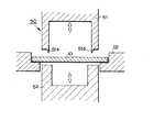
図11に示される構成の成形装置200は、加熱軟化されたブランク外縁部10bの部分を凸条21bと凹溝23aとの間に挟んでこれら凸条21aおよび凹溝23aの形状に対応する凹凸形状を容器フランジ3に賦形するものであるが、ブランク外縁部10bにおける凹凸賦形部分は直前の加熱位置において十分に加熱軟化されているので、クランプ23の下端面に凹凸形状に対応する凹溝23aを環設する必要は必ずしもない。すなわち、図12に示されるように、金型21の上端面に環設された凸条21bと対向する位置においてクランプ23の下端面にフランジに形成される表面側凸部を収容するに十分な凹部23bを環設してもよく、あるいは図13に示されるように、凸条21bの外側においてブランク外縁部10bを挟む脚部23cを有するクランプ23としてもよい。
【0056】
成形装置が作動位置にあるときにクランプがブランク外縁部10bに直接当たると、その圧力でブランク外縁部10bがつぶれて、容器1のフランジ3(図5)に所定の肉厚を保持することができなくなるおそれがある。図12および図13に示される成形装置はこの問題に対する解決手段を有している。すなわち、クランプ23の側方延長部231の下面にパッキング201が貼着されており、成形時にクランプ23が下降したときにパッキング201がブランクホルダ12の周縁部上に弾性的に係合して金型21内のキャビティ21aを気密に保持する。このようにすることにより、クランプ23が作動位置に下降したときにもブランク外縁部10bが圧接されることがなく、それらの間に微小な隙間が与えてもキャビティ21aからの空気漏出を防止することができる。
【0057】
なお、図11〜図13中に示されるブランクホルダ12は、図10に示される好適な実施例によるブランクホルダ120を簡略化して示したものであり、その内周面から突出する方向に付勢されている出没可能なブランク固定ボール37によりブランク外縁部10bが適正位置に保持される。
【0058】
図14は加熱装置についての変形例を示す。この加熱装置180は、上下熱盤190a,190bとこれら熱盤を各々昇降移動させる昇降機構(図示せず)を有して構成される点において前述の加熱装置18(図6)と同様であるが、図15に示されるように、各々の熱盤にはエア噴射孔181,182が厚さ方向に貫通して設けられている。これは、熱盤間に圧接された状態で加熱されたブランク10は溶融して熱盤に付着しやすくなっているため、各加熱位置でのブランク加熱を終了した後に昇降機構により熱盤を離隔させるときに、エア噴射孔181,182を介して高圧エアをブランクに向けて噴射し、熱盤190a,190bに対するブランク10の付着を防止するものである。
【0059】
上下熱盤190a,190bに形成されるエア噴射孔181,182の形状や配列は任意である。図15では、中心距離の異なる位置にそれぞれ複数のエア噴射孔181a,181b;182a,182bを設けている。内径側のエア噴射孔181a,182aと外径側のエア噴射孔181b,182bとで間隔や個数、開口寸法等を異ならせてもよい。また、図15では上下熱盤190a,190bの双方に各々エア噴出孔181,182が設けられているが、これらの一方、特に上方熱盤190aのみにエア噴出孔181を設けてもよい。なお、エア噴射孔181,182の開口寸法が大きくなると熱成形後の容器に転写されてしまうので、転写が防止され、あるいは転写されたとしても目立たない程度の大きさとなるように開口寸法を比較的微小に設定することが好ましい。
【0060】
図14には4対の上下熱盤190a,190bが示されているが、この構成のものが搬送方向に沿って前方および後方に各々設けられており、本実施例で用いられるブランクホルダ12(図2)に保持される合計8個のブランク10を一度に加熱することができる。したがって、これら前方および後方の合計8対の上下熱盤190a,190bはすべて同期して作動される。図1のように数段階の加熱工程が行われる場合には、このような加熱装置180が各加熱工程において設けられる。
【0061】
この実施例におけるブランクホルダ120’は図10に示される構成と略同様であって、金属板である台車34’の穴に4×2=合計8個のリング部材35’が嵌合固定されている。台車34’はチェーンコンベア150に連結されて図14の紙面鉛直方向に移送される。符号40は台車停止位置補正手段であり、ブランクホルダ120’の搬送方向における所定位置に左右両側に一対設けられている。この台車停止位置補正手段40は、ブランクホルダ120’が所定の加熱位置近傍に移送されて該位置で停止した後に先端のシリンダ41が下方に延びて、台車34’の左右両側に突設された突起42と係合することにより台車34の停止位置を補正する。
【0062】
台車停止位置手段装置40により台車34は適正位置に停止するが、さらにこの適正位置に停止した台車34’上のリング部材35’に支持されたブランク10を各対の上下熱盤190a,190b間に厳密に位置規制することが望まれる。この目的で採用される位置決め手段30の一例を図9に示したが、異なる構成の位置決め手段300が図15に示されている。この位置決め手段300にあっては、上方の熱盤190aを取り囲むように設けられたリング状のブランク押さえ枠39が上方熱盤190aと一体に昇降移動する。ブランク押さえ枠39は、加熱工程を行うときに退避位置(図14)から作動位置(図15)に下降する上方熱盤190aと共に下降して、ブランクホルダ120’のリング部材35’を嵌合し、もって該リング部材35’に支持されたブランク10を所定位置に位置決めする。
【0063】
本発明は単層または多層系のプラスチックシートブランクから容器を熱成形する場合に有用であるが、特に装置工程内にハーフノッチ機構を設けることにより、容器の表面層とその下の層との間の層間剥離強度をコントロールした多層系プラスチック容器のフランジ内縁部全周にハーフノッチを設け、その外周に蓋材をタイトシールすることで高密封性と易開封性とを両立させた容器を製造する場合にその効果を発揮する。
【0064】
このようなハーフノッチ機構は、ブランク供給位置(図1におけるブランクホルダー12’上にある位置)と加熱位置との間、加熱位置と成形位置との間、あるいは成形直後の位置に設けることができ、その構成例が図16に示されている。このハーフノッチ機構50は、ブランクホルダー12上に支持されてコンベア15により搬送されるブランク10の搬送面の上方および下方に対向配置される一対の昇降部材51および52を有する。上方昇降部材51の下端にはリング状のノッチ刃51aが設けられ、下方昇降部材52は受け台52として働く。ブランクホルダー12上のブランク10がハーフノッチ機構50に投入されたときにコンベア15が所定時間停止し、それまで退避していた上方および下方の昇降部材51および52が互いに近接する方向に移動して、ブランク10の上面側からノッチ刃51aに応じた深度のノッチを形成する。その後、昇降部材51が上昇すると共に昇降部材52が下降し、コンベア15による搬送が再開される。
【0065】
また、成形装置20(図7,図8),200(図11)におけるクランプ23の下端にリング状のノッチ刃51aを設け、容器成形と同時にノッチ形成を行うようにしてもよい(図17参照)。図17より明らかなように、ノッチは、ブランク10の成形部10aと外縁部10bとの境界部分に、ブランク全周に亘って形成される。
【0066】
あるいは、加熱装置18における上方熱盤19a(図6),190a(図14,図15)と同期して昇降するノッチ刃51aを該上方熱盤の周囲にリング状に設け、加熱と同時にノッチ形成を行うようにしてもよい(図18参照)。あるいは、上方熱盤19a,190aの径をブランクのフランジ内縁相当部に至るまで拡大し、その外縁にノッチ刃を設け、上方熱盤とノッチ刃とを一体化してもよい。図1に示すように複数の加熱装置18a〜18cが設けられる場合は、少なくともそのうちの一の加熱装置においてその上方熱盤19a,190aを取り巻くようにノッチ刃51aを取り付けるか、あるいは熱盤と一体化したノッチ刃を設けることができる。
【0067】
なお、ノッチ刃51aによりブランク10の上面側から形成されるノッチは、前述のように容器内面層の破断強度をその下の層との間の剥離強度よりも小さくするに十分な深さに形成することが必要であり、その深さの限度はブランク10の全厚を貫通しないことである。また、たとえば中間層にEVOH、PVDS等を用いて酸素バリアー性を高めたブランクシートのように特定の層を介在させることによって高付加価値を持たせたブランクシートが用いられる場合には、その高付加価値層を破断しない深さのノッチとすることが好ましい。ブランク10に形成されるノッチの深さは、ノッチ刃51aを温度制御可能に設けることによって容易にコントロールすることが可能となる。
【0068】
以上に本発明の好適な実施例について図面を参照して説明したが、本発明はこれら実施例に限定されず、特許請求の範囲に記載された事項の範囲内において様々な変形態様を取ることができる。
【0069】
【発明の効果】
本発明によれば、プラスチックシートから打ち抜いて得られるブランクを使用して容器を熱成形するため、プラスチックシート面積に対する容器獲得率が高く、製品歩留まりが良く安価に容器を提供することができる。また、シートから打ち抜いたブランクをそのまま使用できるため、単層シートはもちろん、多層系のシートからの容器成形にも適している。
【0070】
ブランクの上下から熱盤を当てて数段階で直接加熱することにより、ブランク温度を均一且つ短時間に加熱することができるため、生産効率に優れている。
【0071】
また、容器フランジとなるブランク外縁部を固相域に維持するために特別な手段を必要とせず、熱伝導でブランク外縁部が膨張変化することもないので冷却手段を設ける必要がない等、コスト的にも有利である。
【0072】
さらに、フランジ外縁部は加熱成形後も元々のブランクの肉厚が実質的に維持されるため、フランジの肉厚精度が高く、フランジ部において行われるシール性も良好となる。
【図面の簡単な説明】
【図1】 本発明の一実施例によるプラスチック容器成形装置の概略構成を示す図である。
【図2】 本実施例装置に用いられるブランクホルダの斜視図である。
【図3】 ブランクホルダのブランク保持部を示す断面図である。
【図4】 ブランクホルダのブランク保持部にブランク供給装置からブランクを供給した状態を示す図3と同様の断面図である。
【図5】 本実施例装置により成形されるプラスチック容器の斜視図である。
【図6】 本実施例装置における加熱装置とブランクホルダのブランク保持部に保持されるブランクとの間の位置関係を示す断面図である。
【図7】 本実施例装置における成形装置とブランクホルダのブランク保持部に保持されるブランクとの間の成形処理開始前の位置関係を示す断面図である。
【図8】 本実施例装置における成形装置とブランクホルダのブランク保持部に保持されるブランクとの間の成形処理中の位置関係を示す断面図である。
【図9】 本実施例装置においてブランクホルダのブランク保持部に保持されるブランクを加熱装置および成形装置に対して自動センタリングするために採用される位置決め装置を示す断面図である。
【図10】 ブランクホルダについての変形例を示す一部破断正面図である。
【図11】 容器成形と同時にフランジに凹凸を賦形するように構成された成形装置を作動位置にあるものとして示す断面図である。
【図12】 容器成形と同時にフランジに凹凸を賦形する成形装置の別の構成例を示す部分断面図である。
【図13】 容器成形と同時にフランジに凹凸を賦形する成形装置のさらに別の構成例を示す部分断面図である。
【図14】 加熱装置についての別の構成例を上下熱盤が退避位置にあるものとして示す正面図である。
【図15】 図14の加熱装置の主要部を上下熱盤が作動位置にあるものとして示す拡大断面図である。
【図16】 ノッチ機構の一例を退避位置にあるものとして示す断面図である。
【図17】 ノッチ機構が組み込まれた成形装置を示す図8と同様の断面図である。
【図18】 ノッチ機構が組み込まれた加熱装置を示す図6と同様の断面図である。
【符号の説明】
1 プラスチック容器
2 容器本体
3 容器フランジ
10 プラスチックブランク
11 シュータ
12,120,120’ ブランクホルダー
13 ブランク保持部
14a 金型挿入部
14b フランジ支持部
15 コンベア
16 ブランク供給装置
18 加熱装置
19a,19b;190a,190b 上下熱盤
20,200 成形装置
21 金型
21a キャビティ
22 プラグ
23 クランプ
24 圧空導入口
25 真空吸引口
26 冷却装置
28 容器取り出し装置
30,300 位置決め装置
31 開口
32 シリンダ
33 突起(センタリングプラグ)
34,34’ 金属板(台車)
35,35’ リング部材
36 ストッパリング
37 ブランク固定ボール
38 Oリング(付勢手段)
39 ブランク押さえ枠
40 台車停止位置補正手段
41 シリンダ
42 突起
50 ハーフノッチ機構(ノッチ形成手段)
51 上方昇降部材
51a ノッチ刃
52 下方昇降部材(受け台)
150 チェーンコンベア
181,182 エア噴射孔
201 パッキング[0001]
BACKGROUND OF THE INVENTION
The present invention relates to a plastic container having a flange.Thermoforming equipmentIn particular, containers from thermoplastic sheets such as polypropylene, polyethylene, polyethylene terephthalate, polyvinyl chloride, etc.Thermoforming equipmentAbout.
[0002]
[Prior art]
Conventionally, various techniques for manufacturing containers from plastic pieces have been proposed. For example, Japanese Patent Application Laid-Open No. 47-4588 discloses a method of casting a plastic sheet piece cut into a square shape into a circular disk and press-molding it into a container. This method is called scrapless molding (SFP) and is a technique that is actually used. However, since this technique is to cast a circular disk from a square plastic sheet piece, strain remains in the circular disk, and when a multilayer sheet is used, the circular disk is maintained while maintaining a uniform layer structure. It is difficult to obtain, and further requires a complicated and large-sized apparatus for casting and pressure molding, resulting in poor productivity and lack of versatility.
[0003]
Many other techniques for casting a circular disk from a plastic piece and then container-molding the circular disk have been proposed, but all have the same problems as described above.
[0004]
Japanese Patent Publication No. 48-11817 describes a cold forming method for obtaining a container having a uniform wall thickness from a specially shaped plastic blank. This technique is unsuitable for system sheet blanks.
[0005]
Japanese Laid-Open Patent Publication No. 47-8089 proposes a method of heating a plastic blank while maintaining continuous contact between heating plates. According to this technique, a heating system installed in parallel is proposed. The plastic blank is transported and heated while sliding between the plates. If any deviation occurs in the temperature of the plate or the slipperiness of the surface of the plastic blank, the blank is deformed and has not been put into practical use.
[0006]
In Japanese Patent Publication No. 6-88328 and Japanese Patent Laid-Open No. 2-150338, the outer edge of a plastic blank is maintained and fixed in a solid phase region, and only the molding region at the center is heated to a molten phase to mold a retortable container. Techniques to do this have been proposed. However, since this technique employs a so-called indirect heating method in which the blank is heated by placing it in an oven having a temperature equal to or higher than the melting point of the plastic for a predetermined time, the outer edge of the blank is maintained in the solid phase region. Therefore, special means must be adopted, and a disadvantage in terms of cost cannot be avoided. In addition, since the entire molding region is heated to a high temperature in the blank held in the oven for a long time, the outer edge tends to expand and change due to heat conduction. There was also a new problem of having to use it together.
[0007]
[Problems to be solved by the invention]
The object of the present invention is to eliminate these disadvantages of the prior art and efficiently produce containers from plastic blanks.
[0008]
(Delete)
[0009]
[Means for Solving the Problems]
That is, according to claim 1A thermoforming apparatus for a plastic container according to the present invention is an apparatus for thermoforming a plastic container using a plastic blank punched out from a thermoplastic plastic sheet, and has a flange supporting part for supporting an outer edge of the blank, thereby forming the blank. A blank holding means for holding; a conveying means for conveying the blank holding means in a predetermined direction along a predetermined conveying path; a blank supplying means for supplying a blank to the blank holding means at a predetermined blank supply position on the conveying path; At the blank heating position provided in the conveyance direction ahead of the blank supply position in the conveyance path, the plastic plate is heated by direct heating by applying a heating plate from both sides to the molding area inside the blank outer edge supported by the flange support portion of the blank holding means. Heating means for heating to a predetermined moldable temperature; A forming means for forming a forming zone heated by the heating means while sandwiched and fixed blank outer edge than the vertical in container forming position provided in the conveying direction ahead of the blank heating position into a predetermined container shape in the conveying path,The blank holding means includes a ring member that is fitted and fixed to each of a plurality of openings formed in the substrate, a blank fixing member that can be projected and retracted toward a flange support portion of the ring member, and a blank fixing Biasing means for biasing the member in the direction of projecting into the flange support portion;It is characterized by becoming.
[0010]
(Delete)
[0011]
Claim 2IsClaim 1The plastic container thermoforming apparatus has a positioning means for centering the blank holding means at a predetermined position with respect to the heating means and / or the forming means.
[0012]
Claim 3IsClaim 2In the plastic container thermoforming apparatus, the positioning means has a cylinder fixed at a predetermined position of the blank holding means, and the cylinder when the blank holding means is centered at a predetermined position with respect to the heating means and / or the molding means. And a centering plug provided in the heating means and / or the forming means so as to be inserted and fitted into the housing.
[0013]
[0014]
[0015]
[0016]
[0017]
[0018]
A thermoforming apparatus for a plastic container according to the present invention according to claim 9 is an apparatus for thermoforming a plastic container using a plastic blank punched out from a thermoplastic sheet, and is a flange support for supporting the outer edge of the blank. A blank holding means for holding a blank by having a section, a conveying means for conveying the blank holding means in a predetermined direction along a predetermined conveying path, and a blank holding means at a predetermined blank supply position on the conveying path. A heating plate is provided on both sides of the blank supply means to be supplied and a molding region inside the blank outer edge portion supported by the flange support portion of the blank holding means at the blank heating position provided in the conveyance direction forward from the blank supply position in the conveyance path. Predetermined temperature at which plastic thermoforming is possible by direct heating Molding that molds the molding region heated by the heating means into a predetermined container shape while sandwiching and fixing the outer edge of the blank from the top and bottom at the heating means for heating and the container forming position provided in the transport direction forward from the blank heating position in the transport path Means, andA molding means is disposed on one side of the conveyance path of the blank holding means so as to be movable in proximity to the conveyance path, and a mold that defines the outer shape of the container body to be manufactured, and the other side of the conveyance path A substantially cylindrical clamp disposed so as to be movable in proximity to the transport path, and a hermetic space forming means for moving the mold and the clamp in a direction close to each other to form an airtight space therebetween And a pressing means for pressing the blank in the hermetic space against the mold when the hermetic space is formed between the mold and the clamp.
[0019]
Claim 10IsClaim 9The plastic container thermoforming apparatus is characterized in that the press contact means includes a plug provided in the clamp so as to be movable relative to the clamp.
[0020]
Claim 11IsClaim 9 or 10In the plastic container thermoforming apparatus, the pressure contact means introduces compressed air into the clamp toward the blank during molding and / or vacuum suction means for vacuum suction of the mold cavity from the opposite side of the blank during molding It is characterized by providing.
[0021]
Claim 12IsClaims 9 to 11In any one of the plastic container thermoforming apparatuses, the airtight space forming means is provided on the lower surface of the clamp, and can be elastically engaged with the upper surface of the blank holding means when the clamp moves close to the mold. It is provided with a packing.
[0022]
Claim 13IsClaims 9 to 12In any one of the plastic container thermoforming apparatuses, the molding means includes a concavo-convex shaping means for shaping the concavo-convex shape having a convex surface on the outer peripheral portion of the molding region heated by the heating means into the container flange. It is further provided with the feature.
[0023]
[0024]
Claim 15IsClaim 14In the plastic container thermoforming apparatus, the notch forming means is provided between the blank supply position and the blank heating position, between the blank heating position and the container forming position, or at least one in front of the container forming position in the transport direction. It is characterized by that.
[0025]
Claim 16IsClaim 14In the plastic container thermoforming apparatus, the notch forming means is provided from a notch blade provided around the upper heating plate in the heating means and moving up and down in synchronization with the heating plate, or a notch blade integrated with the heating plate. It is characterized by becoming.
[0026]
Claim 17IsClaim 14In a plastic container thermoforming device,The notch forming means comprises a ring-shaped notch blade integrally provided at the lower end of the clamp.It is characterized by that.
[0027]
[0028]
The present invention is capable of efficiently thermoforming a plastic container from an arbitrary plastic sheet, and the plastic sheet includes polyolefin resins such as polypropylene and polyethylene, polystyrene resins, polyamide resins, and polyester resins. Alternatively, a mixture thereof, a thermoplastic elastomer, a resin in which various additives or inorganic fillers are mixed in an amount of 5 to 70% by weight, and a gas barrier such as an ethylene vinyl alcohol copolymer, polyvinyl chloride, or polyvinylidene chloride. A single layer or multilayer plastic sheet made of any thermoplastic resin material such as a resin having a property and an inorganic filler mixed with 10 to 80% by weight can be used.
[0029]
DETAILED DESCRIPTION OF THE INVENTION
A plastic container molding apparatus according to an embodiment of the present invention will be described below with reference to the accompanying drawings. This forming apparatus is configured as an apparatus for continuously manufacturing a
[0030]
Referring to FIG. 1, a circular flat blank blank punched out from a PP sheet corresponding to the outer diameter of a container as a final product is supplied to a shooter 11. In this embodiment, the
[0031]
The configuration of the
[0032]
The
[0033]
The blank holder 12 (12 ') that has reached the lower position of the shooter 11 stops at the position for a predetermined time, and the blank is supplied from the shooter 11 during that time. The specific configuration of the supply means at this time is not limited in the present invention, but in this embodiment, an
[0034]
Since the unheated blank 10 supplied from the shooter 11 holds a circular flat plate punched out from the PP sheet, the blank is placed with the outer edge corresponding to the flange of the container placed on the
[0035]
The
[0036]
The heating temperature of the blank 10 in the heating process varies depending on the use of the food container to be manufactured, that is, the contents contained in the container, and in a container such as jelly, a temperature lower than 165 ° C. which is the melting point of PP, for example, As described above, it can be set to 160 ° C. In the case of adding cooked rice (when manufacturing a container for so-called packed rice), in order to prevent the container from being deformed even when sterilized by heating at a high temperature of 130 ° C. or higher after encapsulation, at least the final It is preferable to set the hot platen temperature to a temperature higher than the melting point of PP of 165 ° C. to eliminate as much as possible the molding strain remaining in the container after molding.
[0037]
As shown in FIG. 6, each
[0038]
When the blank heating at the first heating position is completed, the upper and
[0039]
As described above, the
[0040]
Note that even if the blank
[0041]
The
[0042]
When such a
[0043]
In the operating position of FIG. 8, the
[0044]
When the
[0045]
7 and 8 merely show an example of the
[0046]
After the molding process for molding the blank 10 into the
[0047]
Thereafter, the
[0048]
As described above, as the
[0049]
In order to shape the
[0050]
That is, the
[0051]
FIG. 10 shows a further preferred embodiment relating to a blank holder. The
[0052]
The lower part of the
[0053]
An example of the shape of a plastic container that is thermoformed according to the present invention is shown in FIG. 5. In order to prevent secondary contamination of food contents or to maintain a sanitary condition, the container flange 3 is generally made of a plastic film or the like. The lid is heat sealed. In order to improve the heat sealability in this case, it is preferable that the container flange 3 is formed with irregularities having a convex surface.
[0054]
FIG. 11 shows an example of a
[0055]
In the
[0056]
If the clamp directly hits the blank
[0057]
The
[0058]
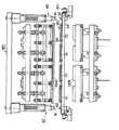
FIG. 14 shows a modification of the heating device. The
[0059]
The shape and arrangement of the air injection holes 181 and 182 formed in the upper and
[0060]
FIG. 14 shows four pairs of upper and
[0061]
The
[0062]
The
[0063]
The present invention is useful when a container is thermoformed from a single-layer or multilayer plastic sheet blank. In particular, by providing a half-notch mechanism in the apparatus process, a space between the surface layer of the container and the layer below it is provided. A multi-layer plastic container with a controlled delamination strength is provided with a half notch on the entire inner periphery of the flange and tightly sealed with a lid on the outer periphery to produce a container that achieves both high sealing performance and easy opening. Show its effect in some cases.
[0064]
Such a half-notch mechanism can be provided between the blank supply position (position on the blank holder 12 'in FIG. 1) and the heating position, between the heating position and the molding position, or immediately after molding. An example of the configuration is shown in FIG. The half-
[0065]
In addition, a ring-shaped notch blade 51a may be provided at the lower end of the
[0066]
Alternatively, a notch blade 51a that moves up and down in synchronization with the
[0067]
The notch formed from the upper surface side of the blank 10 by the notch blade 51a is formed to a depth sufficient to make the breaking strength of the inner surface layer of the container smaller than the peel strength between the lower layer and the lower layer as described above. And the depth limit is that it does not penetrate the entire thickness of the blank 10. For example, when a blank sheet having a high added value by using a specific layer is used, such as a blank sheet having an oxygen barrier property enhanced by using EVOH, PVDS or the like for the intermediate layer, It is preferable to make the value-added layer a notch that does not break. The depth of the notch formed in the blank 10 can be easily controlled by providing the notch blade 51a so that the temperature can be controlled.
[0068]
Although the preferred embodiments of the present invention have been described above with reference to the drawings, the present invention is not limited to these embodiments, and various modifications can be made within the scope of the matters described in the claims. Can do.
[0069]
【The invention's effect】
According to the present invention, since a container is thermoformed using a blank obtained by punching from a plastic sheet, the container acquisition rate with respect to the area of the plastic sheet is high, the product yield is good, and the container can be provided at low cost. Moreover, since the blank punched out from the sheet can be used as it is, it is suitable for forming a container from a multilayer sheet as well as a single-layer sheet.
[0070]
Since the blank plate can be heated uniformly in a short time by applying a heating plate from the top and bottom of the blank and directly heating in several stages, the production efficiency is excellent.
[0071]
In addition, there is no need for special means to maintain the blank outer edge that becomes the container flange in the solid phase region, and the blank outer edge does not expand and change due to heat conduction. This is also advantageous.
[0072]
Further, since the thickness of the original blank is substantially maintained after the heat forming at the flange outer edge portion, the thickness accuracy of the flange is high and the sealing performance performed at the flange portion is also good.
[Brief description of the drawings]
FIG. 1 is a diagram showing a schematic configuration of a plastic container molding apparatus according to an embodiment of the present invention.
FIG. 2 is a perspective view of a blank holder used in the apparatus of this embodiment.
FIG. 3 is a cross-sectional view showing a blank holding portion of the blank holder.
4 is a cross-sectional view similar to FIG. 3, showing a state in which a blank is supplied from a blank supply device to a blank holding portion of the blank holder.
FIG. 5 is a perspective view of a plastic container molded by the apparatus of this embodiment.
FIG. 6 is a cross-sectional view showing a positional relationship between a heating device and a blank held by a blank holding portion of a blank holder in the apparatus of the present embodiment.
FIG. 7 is a cross-sectional view showing a positional relationship between the forming apparatus in the present embodiment apparatus and a blank held by the blank holder of the blank holder before starting the forming process.
FIG. 8 is a cross-sectional view showing a positional relationship during a molding process between a molding device and a blank held by a blank holder of a blank holder in the apparatus of the present example.
FIG. 9 is a cross-sectional view showing a positioning device employed for automatically centering a blank held by a blank holding portion of a blank holder with respect to a heating device and a forming device in the present embodiment device.
FIG. 10 is a partially broken front view showing a modification of the blank holder.
FIG. 11 is a cross-sectional view showing a molding apparatus configured to shape irregularities on a flange at the same time as container molding, assuming that it is in an operating position.
FIG. 12 is a partial cross-sectional view showing another configuration example of a molding apparatus that shapes irregularities on a flange simultaneously with container molding.
FIG. 13 is a partial cross-sectional view showing still another configuration example of a molding apparatus that shapes irregularities on a flange simultaneously with container molding.
FIG. 14 is a front view showing another example of the configuration of the heating device, assuming that the upper and lower heating plates are in the retracted position.
15 is an enlarged cross-sectional view showing the main part of the heating apparatus of FIG. 14 with the upper and lower heating plates in the operating position.
FIG. 16 is a cross-sectional view showing an example of the notch mechanism as being in the retracted position.
FIG. 17 is a cross-sectional view similar to FIG. 8 showing a molding apparatus incorporating a notch mechanism.
18 is a cross-sectional view similar to FIG. 6, showing a heating device incorporating a notch mechanism.
[Explanation of symbols]
1 Plastic container
2 Container body
3 Container flange
10 Plastic blank
11 Shuta
12, 120, 120 'blank holder
13 Blank holding part
14a Mold insertion part
14b Flange support
15 Conveyor
16 Blank feeder
18 Heating device
19a, 19b; 190a, 190b
20,200 Molding equipment
21 Mold
21a cavity
22 plug
23 Clamp
24 Air pressure inlet
25 Vacuum suction port
26 Cooling device
28 Container take-out device
30,300 Positioning device
31 opening
32 cylinders
33 Protrusion (centering plug)
34, 34 'metal plate (cart)
35, 35 'ring member
36 Stopper ring
37 Blank fixed ball
38 O-ring (biasing means)
39 Blank holding frame
40 Bogie stop position correction means
41 cylinders
42 Protrusions
50 Half-notch mechanism (notch forming means)
51 Up and down member
51a Notch blade
52 Lower elevating member (cradle)
150 Chain conveyor
181 and 182 Air injection holes
201 Packing
Claims (18)
Translated fromJapanesePriority Applications (5)
| Application Number | Priority Date | Filing Date | Title |
|---|---|---|---|
| JP21972198AJP4220023B2 (en) | 1997-09-01 | 1998-07-16 | Thermoforming equipment for plastic containers |
| KR1019980035872AKR19990029420A (en) | 1997-09-01 | 1998-09-01 | Thermoforming method and apparatus of plastic container |
| TW087114471ATW446615B (en) | 1997-09-01 | 1998-09-01 | Method and apparatus for thermoforming of plastic vessel |
| US09/266,087US20020079617A1 (en) | 1998-07-16 | 1999-03-10 | Plastic container thermoforming system |
| EP99105667AEP0972627A3 (en) | 1998-07-16 | 1999-03-19 | Thermoforming system for plastic containers |
Applications Claiming Priority (3)
| Application Number | Priority Date | Filing Date | Title |
|---|---|---|---|
| JP9-250122 | 1997-09-01 | ||
| JP25012297 | 1997-09-01 | ||
| JP21972198AJP4220023B2 (en) | 1997-09-01 | 1998-07-16 | Thermoforming equipment for plastic containers |
Publications (2)
| Publication Number | Publication Date |
|---|---|
| JPH11147251A JPH11147251A (en) | 1999-06-02 |
| JP4220023B2true JP4220023B2 (en) | 2009-02-04 |
Family
ID=26523296
Family Applications (1)
| Application Number | Title | Priority Date | Filing Date |
|---|---|---|---|
| JP21972198AExpired - Fee RelatedJP4220023B2 (en) | 1997-09-01 | 1998-07-16 | Thermoforming equipment for plastic containers |
Country Status (3)
| Country | Link |
|---|---|
| JP (1) | JP4220023B2 (en) |
| KR (1) | KR19990029420A (en) |
| TW (1) | TW446615B (en) |
Families Citing this family (12)
| Publication number | Priority date | Publication date | Assignee | Title |
|---|---|---|---|---|
| FR2796039A1 (en)* | 1999-07-09 | 2001-01-12 | Mobile | METHOD FOR THERMOFORMING POTS AND DEVICE FOR IMPLEMENTING SAME |
| ITMO20130214A1 (en)* | 2013-07-26 | 2015-01-27 | Sarong Spa | CAPSULE FOR BEVERAGES AND ITS APPARATUS AND METHOD OF CONSTRUCTION |
| KR101354283B1 (en)* | 2013-09-02 | 2014-01-24 | 주식회사 코빅푸드 | Method for manufacturing package of a meat for steak |
| ITUB20155474A1 (en) | 2015-11-11 | 2017-05-11 | Nike Innovate Cv | EQUIPMENT, AND ITS PROCEDURE, FOR THE THERMAL TREATMENT OF FOOTWEAR, IN PARTICULAR SPORTS SHOES |
| US10967543B2 (en)* | 2017-01-18 | 2021-04-06 | Honda Motor Co., Ltd. | Resin molding apparatus |
| TWI722417B (en) | 2018-04-25 | 2021-03-21 | 荷蘭商耐克創新有限合夥公司 | System and methods for preparing article for thermoforming |
| TWI809379B (en) | 2018-04-25 | 2023-07-21 | 荷蘭商耐克創新有限合夥公司 | System for thermoforming articles |
| WO2019222683A1 (en)* | 2018-05-18 | 2019-11-21 | Nike Innovate C.V. | System and methods for thermoforming articles |
| JP7044735B2 (en)* | 2019-04-04 | 2022-03-30 | 本田技研工業株式会社 | Resin molding equipment and resin molding method |
| EP3812124B1 (en)* | 2019-10-23 | 2023-06-21 | The Stanley Works Israel Ltd. | Selective thermoforming of injection molded parts |
| JP2021075287A (en) | 2019-11-05 | 2021-05-20 | 大和製罐株式会社 | Lid, mold and manufacturing method of lid |
| EP3834943A1 (en)* | 2019-12-11 | 2021-06-16 | Tecan Trading Ag | Combinable cavity tray, assembly of combinable cavity trays, method of manufacturing and use of a combinable cavity tray |
Family Cites Families (4)
| Publication number | Priority date | Publication date | Assignee | Title |
|---|---|---|---|---|
| US3964237A (en)* | 1972-05-10 | 1976-06-22 | Portion Packaging Limited | Apparatus for the production of a product filled container |
| US4419320A (en)* | 1980-10-22 | 1983-12-06 | The Goodyear Tire & Rubber Company | Novel process for deep stretch forming of polyesters |
| JPH04105920A (en)* | 1990-08-24 | 1992-04-07 | Idemitsu Petrochem Co Ltd | Method and device for thermoforming thin wall resin product |
| FR2766123B1 (en)* | 1997-07-21 | 1999-10-08 | Erca | INSTALLATION AND METHOD FOR MANUFACTURING CONTAINERS BY THERMOFORMING |
- 1998
- 1998-07-16JPJP21972198Apatent/JP4220023B2/ennot_activeExpired - Fee Related
- 1998-09-01TWTW087114471Apatent/TW446615B/ennot_activeIP Right Cessation
- 1998-09-01KRKR1019980035872Apatent/KR19990029420A/ennot_activeCeased
Also Published As
| Publication number | Publication date |
|---|---|
| JPH11147251A (en) | 1999-06-02 |
| KR19990029420A (en) | 1999-04-26 |
| TW446615B (en) | 2001-07-21 |
Similar Documents
| Publication | Publication Date | Title |
|---|---|---|
| JP4220023B2 (en) | Thermoforming equipment for plastic containers | |
| KR100977109B1 (en) | Thermal forming device for container | |
| CN108349151B (en) | Thermoforming device and thermoforming method | |
| TWI271303B (en) | Twin-sheet thermoforming of plastic fuel tanks | |
| JP2688089B2 (en) | Container suitable for use in retort canning | |
| KR960004347B1 (en) | Method and apparatus for vacuum packaging | |
| AU744880B2 (en) | Apparatus and methods for twin sheet thermoforming | |
| JPH01103424A (en) | Device for thermoforming vessel from plastic blank | |
| EP0972627A2 (en) | Thermoforming system for plastic containers | |
| US4932856A (en) | Apparatus for thermoforming hollow articles | |
| JP4220045B2 (en) | Plastic container manufacturing method and apparatus | |
| MXPA05004385A (en) | Method to produce polyurethane articles and relative device. | |
| US9694533B2 (en) | Method and device for manufacturing containers by thermoforming | |
| US11155022B2 (en) | Device, mould assembly and method for thermoforming of a product from a plastic film | |
| JP2002018882A (en) | Method and equipment for manufacturing plastic molded article having foamed resin layer | |
| US11897646B2 (en) | Blister packaging machine and method for manufacturing blister pack | |
| JP2766595B2 (en) | Forming method of foamed polyethylene terephthalate sheet | |
| JP2005028627A (en) | Method and apparatus for continuously molding crystalline resin | |
| JP4095785B2 (en) | Packaging container manufacturing apparatus, packaging container manufacturing method, and packaging container obtained by this manufacturing method | |
| JPS63197627A (en) | Apparatus for molding pet resin sheet and other crystallized resin sheet | |
| JP2007090843A (en) | Apparatus and method for forming vessel lid | |
| JPH0528653B2 (en) | ||
| JP2000185319A (en) | Molding method of thermoplastic resin molding | |
| CN116653293A (en) | Laminating device and laminating system | |
| JPS63297027A (en) | Method and apparatus for molding thermoplastic resin continuously in two steps |
Legal Events
| Date | Code | Title | Description |
|---|---|---|---|
| A711 | Notification of change in applicant | Free format text:JAPANESE INTERMEDIATE CODE: A712 Effective date:20041118 | |
| A521 | Written amendment | Free format text:JAPANESE INTERMEDIATE CODE: A821 Effective date:20041118 | |
| A621 | Written request for application examination | Free format text:JAPANESE INTERMEDIATE CODE: A621 Effective date:20050704 | |
| A711 | Notification of change in applicant | Free format text:JAPANESE INTERMEDIATE CODE: A711 Effective date:20060919 | |
| A521 | Written amendment | Free format text:JAPANESE INTERMEDIATE CODE: A821 Effective date:20060919 | |
| A977 | Report on retrieval | Free format text:JAPANESE INTERMEDIATE CODE: A971007 Effective date:20070621 | |
| A131 | Notification of reasons for refusal | Free format text:JAPANESE INTERMEDIATE CODE: A131 Effective date:20080610 | |
| A521 | Written amendment | Free format text:JAPANESE INTERMEDIATE CODE: A523 Effective date:20080807 | |
| TRDD | Decision of grant or rejection written | ||
| A01 | Written decision to grant a patent or to grant a registration (utility model) | Free format text:JAPANESE INTERMEDIATE CODE: A01 Effective date:20081014 | |
| A01 | Written decision to grant a patent or to grant a registration (utility model) | Free format text:JAPANESE INTERMEDIATE CODE: A01 | |
| A61 | First payment of annual fees (during grant procedure) | Free format text:JAPANESE INTERMEDIATE CODE: A61 Effective date:20081113 | |
| FPAY | Renewal fee payment (event date is renewal date of database) | Free format text:PAYMENT UNTIL: 20111121 Year of fee payment:3 | |
| R150 | Certificate of patent or registration of utility model | Free format text:JAPANESE INTERMEDIATE CODE: R150 | |
| FPAY | Renewal fee payment (event date is renewal date of database) | Free format text:PAYMENT UNTIL: 20111121 Year of fee payment:3 | |
| FPAY | Renewal fee payment (event date is renewal date of database) | Free format text:PAYMENT UNTIL: 20121121 Year of fee payment:4 | |
| LAPS | Cancellation because of no payment of annual fees |