JP4217546B2 - switch - Google Patents
switchDownload PDFInfo
- Publication number
- JP4217546B2 JP4217546B2JP2003167677AJP2003167677AJP4217546B2JP 4217546 B2JP4217546 B2JP 4217546B2JP 2003167677 AJP2003167677 AJP 2003167677AJP 2003167677 AJP2003167677 AJP 2003167677AJP 4217546 B2JP4217546 B2JP 4217546B2
- Authority
- JP
- Japan
- Prior art keywords
- contact
- rubber contact
- operation knob
- switch
- pressing member
- Prior art date
- Legal status (The legal status is an assumption and is not a legal conclusion. Google has not performed a legal analysis and makes no representation as to the accuracy of the status listed.)
- Expired - Fee Related
Links
- 230000002159abnormal effectEffects0.000description6
- 230000000694effectsEffects0.000description4
- 238000006073displacement reactionMethods0.000description1
- 238000004519manufacturing processMethods0.000description1
- 239000000463materialSubstances0.000description1
- 230000007935neutral effectEffects0.000description1
- 239000000758substrateSubstances0.000description1
- 229920003002synthetic resinPolymers0.000description1
- 239000000057synthetic resinSubstances0.000description1
Images


Classifications
- H—ELECTRICITY
- H01—ELECTRIC ELEMENTS
- H01H—ELECTRIC SWITCHES; RELAYS; SELECTORS; EMERGENCY PROTECTIVE DEVICES
- H01H13/00—Switches having rectilinearly-movable operating part or parts adapted for pushing or pulling in one direction only, e.g. push-button switch
- H01H13/70—Switches having rectilinearly-movable operating part or parts adapted for pushing or pulling in one direction only, e.g. push-button switch having a plurality of operating members associated with different sets of contacts, e.g. keyboard
- H01H13/702—Switches having rectilinearly-movable operating part or parts adapted for pushing or pulling in one direction only, e.g. push-button switch having a plurality of operating members associated with different sets of contacts, e.g. keyboard with contacts carried by or formed from layers in a multilayer structure, e.g. membrane switches
- H01H13/705—Switches having rectilinearly-movable operating part or parts adapted for pushing or pulling in one direction only, e.g. push-button switch having a plurality of operating members associated with different sets of contacts, e.g. keyboard with contacts carried by or formed from layers in a multilayer structure, e.g. membrane switches characterised by construction, mounting or arrangement of operating parts, e.g. push-buttons or keys
- H01H13/7065—Switches having rectilinearly-movable operating part or parts adapted for pushing or pulling in one direction only, e.g. push-button switch having a plurality of operating members associated with different sets of contacts, e.g. keyboard with contacts carried by or formed from layers in a multilayer structure, e.g. membrane switches characterised by construction, mounting or arrangement of operating parts, e.g. push-buttons or keys characterised by the mechanism between keys and layered keyboards
- H—ELECTRICITY
- H01—ELECTRIC ELEMENTS
- H01H—ELECTRIC SWITCHES; RELAYS; SELECTORS; EMERGENCY PROTECTIVE DEVICES
- H01H2215/00—Tactile feedback
- H01H2215/004—Collapsible dome or bubble
- H—ELECTRICITY
- H01—ELECTRIC ELEMENTS
- H01H—ELECTRIC SWITCHES; RELAYS; SELECTORS; EMERGENCY PROTECTIVE DEVICES
- H01H2221/00—Actuators
- H01H2221/008—Actuators other then push button
- H01H2221/018—Tumbler
- H—ELECTRICITY
- H01—ELECTRIC ELEMENTS
- H01H—ELECTRIC SWITCHES; RELAYS; SELECTORS; EMERGENCY PROTECTIVE DEVICES
- H01H2221/00—Actuators
- H01H2221/062—Damping vibrations
- H—ELECTRICITY
- H01—ELECTRIC ELEMENTS
- H01H—ELECTRIC SWITCHES; RELAYS; SELECTORS; EMERGENCY PROTECTIVE DEVICES
- H01H23/00—Tumbler or rocker switches, i.e. switches characterised by being operated by rocking an operating member in the form of a rocker button
- H01H23/02—Details
- H01H23/12—Movable parts; Contacts mounted thereon
- H01H23/16—Driving mechanisms
- H—ELECTRICITY
- H01—ELECTRIC ELEMENTS
- H01H—ELECTRIC SWITCHES; RELAYS; SELECTORS; EMERGENCY PROTECTIVE DEVICES
- H01H3/00—Mechanisms for operating contacts
- H01H3/60—Mechanical arrangements for preventing or damping vibration or shock
Landscapes
- Tumbler Switches (AREA)
- Push-Button Switches (AREA)
Description
Translated fromJapanese【0001】
【発明の属する技術分野】
本発明は、ラバーコンタクトを用いたスイッチに関するものである。
【0002】
【従来の技術】
家電製品や車両をはじめとする各種製品には、使用される箇所に要求される性能や機能に応じた種々のスイッチが用いられている。これらスイッチの接点部分には、ラバーコンタクトが多用されている。ラバーコンタクトは、それ自体弾性を有するため、ばね等の機械部品を削減できるという利点がある。
【0003】
ラバーコンタクトは、耐久性の向上や押圧時のフィーリングの向上から、頂点付近が押圧されることが望ましい。そこで、図7に示すスイッチ30が一般的に知られている。すなわち、操作ノブ31とラバーコンタクト32との間にプッシャ33が設けられている。このスイッチ30においては、操作ノブ31の片側が押圧操作されると、操作ノブ31は支点Xを中心に傾動し、プッシャ33が押圧されることで、ラバーコンタクト32が弾性変形しながら接点部34は配線基板35に対して電気的に接続される。
【0004】
【発明が解決しようとする課題】
しかしながら、従来技術のスイッチ30においては、図8に示すように、操作ノブ31が押圧操作されると、操作ノブ31の裏面に形成された操作突起36がプッシャ33に突き当たることによって異音が発生し、ユーザに不快感を与える。
【0005】
本発明は、こうした実情に鑑みてなされたものであり、その目的は、操作体を操作する際に発生する異音を抑制することができるスイッチを提供することにある。
【0006】
【課題を解決するための手段】
上記の課題を解決するために、請求項1に記載の発明では、配線基板上に設けられ弾性変形可能なラバーコンタクトと、前記ラバーコンタクトを変形させる方向に沿って移動する押圧部材と、前記押圧部材に接した状態でラバーコンタクトを変形させるための操作体とを備え、前記操作体を操作することにより、押圧部材を介してラバーコンタクトを弾性変形させながら同ラバーコンタクトに設けた接点部を前記配線基板に対して電気的に接続可能にしたスイッチにおいて、前記押圧部材には貫通孔が形成され、前記ラバーコンタクトに、操作体が押圧部材に接する面から同操作体に向けて突出され、これに前記操作体が接するように前記押圧部材の貫通孔に挿通される弾性部を設けたことを要旨とする。
【0007】
この構成によれば、操作体が操作されると、この操作体は、まずラバーコンタクトの弾性部に突き当たった後、押圧部材に突き当たり、押圧部材によってラバーコンタクトは押圧される。そして、ラバーコンタクトは、弾性変形されながらその接点部が配線基板に接続される。操作体は押圧部材に突き当たるタイミングよりも先にラバーコンタクトの弾性部に突き当たる。このとき、操作体の衝撃が緩和されるため、操作体が押圧部材に突き当たる際に発生する異音を抑制することができる。
【0009】
即ち、この構成によれば、操作体が操作されると後に押圧部材に突き当たるが、弾性部が押圧部材から突出しているため、操作体は押圧部材に突き当たるタイミングよりも先に弾性部と確実に接する。したがって、操作体が押圧部材に突き当たる際に発生する異音の抑制効果が高くなる。
【0010】
請求項2に記載の発明では、請求項1に記載のスイッチにおいて、前記ラバーコンタクトの弾性部は、前記操作体と向き合う面が開口された断面凹状に形成されていることを要旨とする。
この構成によれば、操作体がラバーコンタクトの弾性部に突き当たったときに弾性部が変形し易くなる。操作体が押圧部材に突き当たるときの衝撃力をいっそう緩和することができ、操作体の操作フィーリングが向上することとなる。
【0011】
【発明の実施の形態】
以下、本発明のスイッチをシーソースイッチに具体化した一実施形態を図1〜図5にしたがって説明する。
【0012】
図1,図2に示すように、シーソースイッチ1の本体ケース10内には配線基板11が収容されており、その配線基板11の上面にはラバーコンタクトシート12が敷設されている。ラバーコンタクトシート12上には、ドーム状をなす弾性変形可能な合成樹脂製のラバーコンタクト13が一体的に形成されている。
【0013】
本体ケース10の中央には、ラバーコンタクト13の間に位置するように支持部14が形成されている。支持部14には、ラバーコンタクト13のそれぞれの方向に対して開口するようにガイド部14aが形成され、このガイド部14aには、押圧部材としてのプッシャ15に形成された係合部15aが係合されている。この係合により、プッシャ15は、図1の上下方向つまりラバーコンタクト13を変形させる方向に沿って移動可能となっている。
【0014】
本体ケース10の開口部には、それを塞ぐように操作体としての操作ノブ17が設けられ、この操作ノブ17は、本体ケース10の開口縁に設けられた支軸16によって傾動可能に支持されている。操作ノブ17は、その裏面に前記プッシャ15と向き合うように形成された押圧突部17aを有している。そして、操作ノブ17が押圧操作されることにより、押圧突部17aによってプッシャ15が押圧されるようになっている。プッシャ15が押圧されることにより、ラバーコンタクト13が変形し、その内頂部に設けられた接点部13aと、配線基板11に設けられた端子(図示せず)とが電気的に接続するようになっている。一方、操作ノブ17の押圧操作が解除されることにより、ラバーコンタクト13が押圧前の形状に弾性的に復帰するため、同ラバーコンタクト13の接点部13aと配線基板11に設けられた端子とが離間するようになっている。
【0015】
ラバーコンタクト13の外頂部には、操作ノブ17の押圧突部17aと対峙するように弾性部13bが一体的に形成されている。この弾性部13bは、ラバーコンタクト13と同じ形成材料でもって一体的に形成されている。弾性部13bは、押圧突部17aと向き合う面が開口された断面凹状に形成され、操作ノブ17の操作に伴って押圧突部17aが押圧されることにより弾性的に変形するようになっている。
【0016】
ラバーコンタクト13の弾性部13bは、プッシャ15に形成された貫通孔15bに挿通されており、操作ノブ17の押圧突部17aがプッシャ15に接する接触面15cから突出されている。そのため、図3に示すように、操作ノブ17が押圧操作されると、押圧突部17aがプッシャ15に対して接するよりも先にラバーコンタクト13の弾性部13bに接するようになっている。
【0017】
操作ノブ17における押圧突部17aの先端部には、切欠部17bが形成されている。この切欠部17bの幅Wは、前記ラバーコンタクト13の弾性部13bの直径よりも大きく設定されている。そして、操作ノブ17が所定量押圧操作されると、ラバーコンタクト13の弾性部13bが切欠部17b内に入り込むことにより、操作ノブ17とラバーコンタクト13の接触が回避されるようになっている。
【0018】
次に、上記構成の作用について説明する。
図3に示すように、操作ノブ17の一端部(同図の右側)が押圧操作されると、押圧突部17aがラバーコンタクト13の弾性部13bに対して突き当たり、図4に示すように、押圧突部17aによって弾性部13bが押し潰されながらプッシャ15が押圧される。このとき、押圧突部17aは、プッシャ15よりも先にラバーコンタクト13の弾性部13bに突き当たることにより、操作ノブ17がプッシャ15に与える衝撃は緩和される。
【0019】
図5に示すように、操作ノブ17の一端部が更に押圧操作されると、押圧突部17aの先端部は、接触面15c上を摺動するようにしてラバーコンタクト13の弾性部13bから位置ずれするため、弾性部13bは切欠部17b内に入り込む。このため、押圧突部17aと弾性部13bとは非接触となり、弾性部13bは元の形状に復帰する。
【0020】
また、ラバーコンタクト13が変形したままの状態で、接点部13aは配線基板11上の端子に接続される。
一方、操作ノブ17の押圧操作が解除されると、自身の弾性力によってラバーコンタクト13は元の形状に復帰し、接点部13aが配線基板11上の端子から離間する。この結果、シーソースイッチ1は、図1に示す中立位置に戻る。
【0021】
本実施形態のシーソースイッチ1は以下の効果を奏する。
(1)操作ノブ17が押圧操作されると、その押圧突部17aがプッシャ15よりも先にラバーコンタクト13の弾性部13bに突き当たる。このため、操作ノブ17を押圧した際にプッシャ15に発生する衝撃は、押圧突部17aが弾性部13bに当たることによって緩和され、操作ノブ17がプッシャ15に突き当たる際に発生する異音を抑制することができる。
【0022】
(2)ラバーコンタクト13の弾性部13bは、操作ノブ17の押圧突部17aがプッシャ15に接する面から突出されている。このため、操作ノブ17が押圧操作されたときに、その押圧突部17aがプッシャ15に突き当たる前に確実に弾性部13bに突き当たることになる。したがって、操作ノブ17がプッシャ15に突き当たる際に発生する異音を確実に抑制することができる。
【0023】
(3)ラバーコンタクト13の弾性部13bは、断面凹状に形成されているため、操作ノブ17の押圧突部17aが弾性部13bに突き当たったときに弾性部13bは変形しやすくなっている。したがって、操作ノブ17がプッシャ15に突き当たったときに、操作ノブ17に対する弾性部13bの緩衝効果が高くなるとともに、操作ノブ17の操作フィーリングを向上させることもできる。
【0024】
(4)ラバーコンタクト13の弾性部13bはラバーコンタクト13と一体的に成形されているため、部品点数の増加を抑制でき、製造コストの抑制を図ることができる。
【0025】
(5)弾性部13bは、押圧突部17aと接触した後、切欠部17b内に入り込むことにより、押圧突部17aと非接触になる。このため、操作ノブ17とプッシャ15との間で生じる衝撃が緩和された後には、軽い操作力で操作ノブ17を押圧することができる。したがって、操作ノブ17の操作フィーリングがいっそう向上する。
【0026】
なお、本実施形態は以下のように変更してもよい。
・弾性部13bは、断面凹状に形成されていなくてもよい。例えば、図6に示すように、ラバーコンタクト13の内頂部と外頂部との間に中空部20が設けられてもよい。このようにすれば、操作ノブ17が押圧操作された際、中空部20の付近に位置するラバーコンタクト13の一部が変形し易くなる。
【0027】
・操作ノブ17の押圧突部17aには、切欠部17bが形成されていなくてもよい。この場合でも、弾性部13bがプッシャ15から突出していることにより、押圧突部17aは、弾性部13bに突き当たった後にプッシャ15に突き当たる。
【0028】
・本発明は、シーソースイッチ1以外のスイッチとしてプッシュスイッチに具体化してもよい。
次に、本実施形態及び他の実施形態から把握できる技術的思想について以下に追記する。
【0029】
(1)前記スイッチにおいて、前記操作体における前記弾性部と接する部位には、弾性部の一部が入り込むことが可能な切欠部が設けられていること。
【0030】
(2)前記スイッチにおいて、前記ラバーコンタクトはドーム状に形成され、その内頂部には前記接点部が配置されるとともに外頂部には前記弾性部が配置され、前記ラバーコンタクトの頂部において接点部と弾性部との間には中空部が設けられていること。
【0031】
(3)前記スイッチにおいて、前記弾性部は前記ラバーコンタクトと一体的に形成されていること。
【0032】
【発明の効果】
本発明によれば、操作体を操作する際に発生する異音を抑制することができるスイッチを提供することができる。
【図面の簡単な説明】
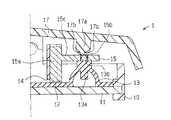
【図1】本実施形態におけるシーソースイッチの断面図。
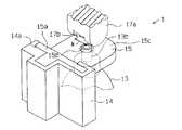
【図2】同じくシーソースイッチにおいて、図1におけるA部の拡大斜視図。
【図3】同じくシーソースイッチの作用を説明するための断面図。
【図4】同じく図3に続くシーソースイッチの作用を説明するための断面図。
【図5】同じく図4に続くシーソースイッチの作用を説明するための断面図。
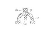
【図6】他の実施形態におけるラバーコンタクトの断面図。
【図7】従来技術におけるシーソースイッチの断面図。
【図8】同じくシーソースイッチの断面図。
【符号の説明】
1…スイッチとしてのシーソースイッチ、11…配線基板、13…ラバーコンタクト、13a…接点部、13b…弾性部、15…押圧部材としてのプッシャ、15b…貫通孔、15c…接触面、17…操作体としての操作ノブ、17a…押圧突部。[0001]
BACKGROUND OF THE INVENTION
The present invention relates to a switch using a rubber contact.
[0002]
[Prior art]
Various switches according to the performance and function required for the place where it is used are used in various products including home appliances and vehicles. Rubber contacts are frequently used for the contact portions of these switches. Since the rubber contact itself has elasticity, there is an advantage that mechanical parts such as a spring can be reduced.
[0003]
The rubber contact is preferably pressed near the apex in order to improve durability and feel during pressing. Therefore, a
[0004]
[Problems to be solved by the invention]
However, in the
[0005]
The present invention has been made in view of such circumstances, and an object of the present invention is to provide a switch capable of suppressing abnormal noise generated when an operating tool is operated.
[0006]
[Means for Solving the Problems]
In order to solve the above-described problems, in the invention according to
[0007]
According to this configuration, when the operating body is operated, the operating bodyfirst hitsthe elastic portion of the rubber contact, then hits the pressing member, and the rubber contact is pressed by the pressing member. The contact portion of the rubber contact is connected to the wiring board while being elastically deformed. The operating body hits the elastic portion of the rubber contact before the timing of hitting the pressing member. At this time, since the impact of the operating body is alleviated, it is possible to suppress abnormal noise that occurs when the operating body hits against the pressing member.
[0009]
That is, according to this configuration, when the operating body is operated, it will abut against the pressing memberlater, but since the elastic portion protrudes from the pressing member, the operating body is surely connected to the elastic portion before the timing of contacting the pressing member. Touch. Therefore, the effect of suppressing abnormal noise generated when the operating body hits the pressing member is enhanced.
[0010]
The invention according to claim2 is characterized in that, inthe switch according to
According to this configuration, the elastic part is easily deformed when the operating body hitsthe elastic part of therubber contact . The impact force when the operating body hits against the pressing member can be further reduced, and the operation feeling of the operating body is improved.
[0011]
DETAILED DESCRIPTION OF THE INVENTION
Hereinafter, an embodiment in which the switch of the present invention is embodied as a seesaw switch will be described with reference to FIGS.
[0012]
As shown in FIGS. 1 and 2, a
[0013]
A
[0014]
An
[0015]
An
[0016]
The
[0017]
A
[0018]
Next, the operation of the above configuration will be described.
As shown in FIG. 3, when one end of the operation knob 17 (the right side in the figure) is pressed, the
[0019]
As shown in FIG. 5, when one end of the
[0020]
Further, the
On the other hand, when the pressing operation of the
[0021]
The
(1) When the
[0022]
(2) The
[0023]
(3) Since the
[0024]
(4) Since the
[0025]
(5) After the
[0026]
In addition, you may change this embodiment as follows.
-The
[0027]
The
[0028]
The present invention may be embodied as a push switch as a switch other than the
Next, technical ideas that can be grasped from this embodiment and other embodiments will be described below.
[0029]
(1) In theswitch , a notch part into which a part of the elastic part can enter is provided in a part of the operating body that contacts the elastic part.
[0030]
(2) In theswitch , the rubber contact is formed in a dome shape, thecontact portion is disposed on an inner top portion thereof, and the elastic portion is disposed on an outer top portion, and thecontact portion is disposed on the top portion of the rubber contact. A hollow part is provided between the elastic part.
[0031]
(3) In theswitch , the elastic portion is formed integrally with the rubber contact.
[0032]
【The invention's effect】
ADVANTAGE OF THE INVENTION According to this invention, the switch which can suppress the abnormal noise which generate | occur | produces when operating an operation body can be provided.
[Brief description of the drawings]
FIG. 1 is a cross-sectional view of a seesaw switch according to an embodiment.
2 is an enlarged perspective view of a portion A in FIG. 1 in the same seesaw switch. FIG.
FIG. 3 is a cross-sectional view for explaining the operation of the seesaw switch.
4 is a cross-sectional view for explaining the operation of the seesaw switch, similarly to FIG. 3. FIG.
FIG. 5 is a cross-sectional view for explaining the operation of the seesaw switch similarly to FIG. 4;
FIG. 6 is a cross-sectional view of a rubber contact according to another embodiment.
FIG. 7 is a cross-sectional view of a seesaw switch in the prior art.
FIG. 8 is a cross-sectional view of the seesaw switch.
[Explanation of symbols]
DESCRIPTION OF
Claims (2)
Translated fromJapanese前記押圧部材には貫通孔が形成され、
前記ラバーコンタクトに、操作体が押圧部材に接する面から同操作体に向けて突出され、これに前記操作体が接するように前記押圧部材の貫通孔に挿通される弾性部を設けたことを特徴とするスイッチ。A rubber contact provided on the wiring board and elastically deformable, a pressing member that moves in a direction in which the rubber contact is deformed, and an operating body for deforming the rubber contact in contact with the pressing member. In the switch, by operating the operating body, the contact portion provided on the rubber contact can be electrically connected to the wiring board while elastically deforming the rubber contact via the pressing member.
A through hole is formed in the pressing member,
The rubber contact isprovided with an elastic portionthat protrudes from the surface in contact with the pressing member toward the operating body, and is inserted into the through hole of the pressing member so that the operating body comes into contact therewith. Switch.
Priority Applications (2)
| Application Number | Priority Date | Filing Date | Title |
|---|---|---|---|
| JP2003167677AJP4217546B2 (en) | 2003-06-12 | 2003-06-12 | switch |
| US10/865,107US6943311B2 (en) | 2003-06-12 | 2004-06-10 | Switch |
Applications Claiming Priority (1)
| Application Number | Priority Date | Filing Date | Title |
|---|---|---|---|
| JP2003167677AJP4217546B2 (en) | 2003-06-12 | 2003-06-12 | switch |
Publications (2)
| Publication Number | Publication Date |
|---|---|
| JP2005005139A JP2005005139A (en) | 2005-01-06 |
| JP4217546B2true JP4217546B2 (en) | 2009-02-04 |
Family
ID=33508995
Family Applications (1)
| Application Number | Title | Priority Date | Filing Date |
|---|---|---|---|
| JP2003167677AExpired - Fee RelatedJP4217546B2 (en) | 2003-06-12 | 2003-06-12 | switch |
Country Status (2)
| Country | Link |
|---|---|
| US (1) | US6943311B2 (en) |
| JP (1) | JP4217546B2 (en) |
Families Citing this family (95)
| Publication number | Priority date | Publication date | Assignee | Title |
|---|---|---|---|---|
| US6726686B2 (en) | 1997-11-12 | 2004-04-27 | Sherwood Services Ag | Bipolar electrosurgical instrument for sealing vessels |
| US7435249B2 (en) | 1997-11-12 | 2008-10-14 | Covidien Ag | Electrosurgical instruments which reduces collateral damage to adjacent tissue |
| US6228083B1 (en) | 1997-11-14 | 2001-05-08 | Sherwood Services Ag | Laparoscopic bipolar electrosurgical instrument |
| US7582087B2 (en) | 1998-10-23 | 2009-09-01 | Covidien Ag | Vessel sealing instrument |
| US7118570B2 (en) | 2001-04-06 | 2006-10-10 | Sherwood Services Ag | Vessel sealing forceps with disposable electrodes |
| US7267677B2 (en) | 1998-10-23 | 2007-09-11 | Sherwood Services Ag | Vessel sealing instrument |
| US7364577B2 (en) | 2002-02-11 | 2008-04-29 | Sherwood Services Ag | Vessel sealing system |
| US20030109875A1 (en) | 1999-10-22 | 2003-06-12 | Tetzlaff Philip M. | Open vessel sealing forceps with disposable electrodes |
| ES2262639T3 (en) | 2001-04-06 | 2006-12-01 | Sherwood Services Ag | SHUTTER AND DIVIDER OF GLASSES WITH BUMPER MEMBERS N OCONDUCTIVES. |
| EP1527747B1 (en) | 2001-04-06 | 2015-09-30 | Covidien AG | Electrosurgical instrument which reduces collateral damage to adjacent tissue |
| US7270664B2 (en) | 2002-10-04 | 2007-09-18 | Sherwood Services Ag | Vessel sealing instrument with electrical cutting mechanism |
| US7276068B2 (en) | 2002-10-04 | 2007-10-02 | Sherwood Services Ag | Vessel sealing instrument with electrical cutting mechanism |
| US7931649B2 (en) | 2002-10-04 | 2011-04-26 | Tyco Healthcare Group Lp | Vessel sealing instrument with electrical cutting mechanism |
| US7799026B2 (en) | 2002-11-14 | 2010-09-21 | Covidien Ag | Compressible jaw configuration with bipolar RF output electrodes for soft tissue fusion |
| EP1601298B1 (en) | 2003-03-13 | 2016-09-07 | Covidien AG | Bipolar concentric electrode assembly for soft tissue fusion |
| US7160299B2 (en) | 2003-05-01 | 2007-01-09 | Sherwood Services Ag | Method of fusing biomaterials with radiofrequency energy |
| CA2523675C (en) | 2003-05-01 | 2016-04-26 | Sherwood Services Ag | Electrosurgical instrument which reduces thermal damage to adjacent tissue |
| JP5137230B2 (en) | 2003-05-15 | 2013-02-06 | コヴィディエン・アクチェンゲゼルシャフト | Tissue sealer with non-conductive variable stop member and method for sealing tissue |
| USD956973S1 (en) | 2003-06-13 | 2022-07-05 | Covidien Ag | Movable handle for endoscopic vessel sealer and divider |
| US7156846B2 (en) | 2003-06-13 | 2007-01-02 | Sherwood Services Ag | Vessel sealer and divider for use with small trocars and cannulas |
| US7150749B2 (en) | 2003-06-13 | 2006-12-19 | Sherwood Services Ag | Vessel sealer and divider having elongated knife stroke and safety cutting mechanism |
| US7857812B2 (en) | 2003-06-13 | 2010-12-28 | Covidien Ag | Vessel sealer and divider having elongated knife stroke and safety for cutting mechanism |
| US9848938B2 (en) | 2003-11-13 | 2017-12-26 | Covidien Ag | Compressible jaw configuration with bipolar RF output electrodes for soft tissue fusion |
| US7367976B2 (en) | 2003-11-17 | 2008-05-06 | Sherwood Services Ag | Bipolar forceps having monopolar extension |
| US7131970B2 (en) | 2003-11-19 | 2006-11-07 | Sherwood Services Ag | Open vessel sealing instrument with cutting mechanism |
| US7500975B2 (en) | 2003-11-19 | 2009-03-10 | Covidien Ag | Spring loaded reciprocating tissue cutting mechanism in a forceps-style electrosurgical instrument |
| US7811283B2 (en) | 2003-11-19 | 2010-10-12 | Covidien Ag | Open vessel sealing instrument with hourglass cutting mechanism and over-ratchet safety |
| US7442193B2 (en) | 2003-11-20 | 2008-10-28 | Covidien Ag | Electrically conductive/insulative over-shoe for tissue fusion |
| US7780662B2 (en) | 2004-03-02 | 2010-08-24 | Covidien Ag | Vessel sealing system using capacitive RF dielectric heating |
| US7195631B2 (en) | 2004-09-09 | 2007-03-27 | Sherwood Services Ag | Forceps with spring loaded end effector assembly |
| US7540872B2 (en) | 2004-09-21 | 2009-06-02 | Covidien Ag | Articulating bipolar electrosurgical instrument |
| US7955332B2 (en) | 2004-10-08 | 2011-06-07 | Covidien Ag | Mechanism for dividing tissue in a hemostat-style instrument |
| US7909823B2 (en) | 2005-01-14 | 2011-03-22 | Covidien Ag | Open vessel sealing instrument |
| US7686804B2 (en) | 2005-01-14 | 2010-03-30 | Covidien Ag | Vessel sealer and divider with rotating sealer and cutter |
| US7491202B2 (en) | 2005-03-31 | 2009-02-17 | Covidien Ag | Electrosurgical forceps with slow closure sealing plates and method of sealing tissue |
| US7879035B2 (en) | 2005-09-30 | 2011-02-01 | Covidien Ag | Insulating boot for electrosurgical forceps |
| ES2381560T3 (en) | 2005-09-30 | 2012-05-29 | Covidien Ag | Insulating sleeve for electrosurgical forceps |
| JP4265591B2 (en)* | 2005-09-30 | 2009-05-20 | ブラザー工業株式会社 | Rubber key device, portable terminal, and image processing device |
| US7922953B2 (en) | 2005-09-30 | 2011-04-12 | Covidien Ag | Method for manufacturing an end effector assembly |
| CA2561034C (en) | 2005-09-30 | 2014-12-09 | Sherwood Services Ag | Flexible endoscopic catheter with an end effector for coagulating and transfecting tissue |
| US7722607B2 (en) | 2005-09-30 | 2010-05-25 | Covidien Ag | In-line vessel sealer and divider |
| US7789878B2 (en) | 2005-09-30 | 2010-09-07 | Covidien Ag | In-line vessel sealer and divider |
| US8298232B2 (en) | 2006-01-24 | 2012-10-30 | Tyco Healthcare Group Lp | Endoscopic vessel sealer and divider for large tissue structures |
| US8241282B2 (en) | 2006-01-24 | 2012-08-14 | Tyco Healthcare Group Lp | Vessel sealing cutting assemblies |
| US8734443B2 (en) | 2006-01-24 | 2014-05-27 | Covidien Lp | Vessel sealer and divider for large tissue structures |
| US8882766B2 (en) | 2006-01-24 | 2014-11-11 | Covidien Ag | Method and system for controlling delivery of energy to divide tissue |
| EP2034499A4 (en) | 2006-06-22 | 2012-01-11 | Covac Co Ltd | Switch responsive to see-saw key |
| US7776037B2 (en) | 2006-07-07 | 2010-08-17 | Covidien Ag | System and method for controlling electrode gap during tissue sealing |
| US8597297B2 (en) | 2006-08-29 | 2013-12-03 | Covidien Ag | Vessel sealing instrument with multiple electrode configurations |
| US8070746B2 (en) | 2006-10-03 | 2011-12-06 | Tyco Healthcare Group Lp | Radiofrequency fusion of cardiac tissue |
| USD649249S1 (en) | 2007-02-15 | 2011-11-22 | Tyco Healthcare Group Lp | End effectors of an elongated dissecting and dividing instrument |
| US8267935B2 (en) | 2007-04-04 | 2012-09-18 | Tyco Healthcare Group Lp | Electrosurgical instrument reducing current densities at an insulator conductor junction |
| US7877853B2 (en) | 2007-09-20 | 2011-02-01 | Tyco Healthcare Group Lp | Method of manufacturing end effector assembly for sealing tissue |
| US7877852B2 (en) | 2007-09-20 | 2011-02-01 | Tyco Healthcare Group Lp | Method of manufacturing an end effector assembly for sealing tissue |
| US8236025B2 (en) | 2007-09-28 | 2012-08-07 | Tyco Healthcare Group Lp | Silicone insulated electrosurgical forceps |
| AU2008221509B2 (en) | 2007-09-28 | 2013-10-10 | Covidien Lp | Dual durometer insulating boot for electrosurgical forceps |
| US9023043B2 (en) | 2007-09-28 | 2015-05-05 | Covidien Lp | Insulating mechanically-interfaced boot and jaws for electrosurgical forceps |
| US8251996B2 (en) | 2007-09-28 | 2012-08-28 | Tyco Healthcare Group Lp | Insulating sheath for electrosurgical forceps |
| US8221416B2 (en) | 2007-09-28 | 2012-07-17 | Tyco Healthcare Group Lp | Insulating boot for electrosurgical forceps with thermoplastic clevis |
| US8235993B2 (en) | 2007-09-28 | 2012-08-07 | Tyco Healthcare Group Lp | Insulating boot for electrosurgical forceps with exohinged structure |
| US8235992B2 (en) | 2007-09-28 | 2012-08-07 | Tyco Healthcare Group Lp | Insulating boot with mechanical reinforcement for electrosurgical forceps |
| US8267936B2 (en) | 2007-09-28 | 2012-09-18 | Tyco Healthcare Group Lp | Insulating mechanically-interfaced adhesive for electrosurgical forceps |
| US8764748B2 (en) | 2008-02-06 | 2014-07-01 | Covidien Lp | End effector assembly for electrosurgical device and method for making the same |
| US8623276B2 (en) | 2008-02-15 | 2014-01-07 | Covidien Lp | Method and system for sterilizing an electrosurgical instrument |
| US8469956B2 (en) | 2008-07-21 | 2013-06-25 | Covidien Lp | Variable resistor jaw |
| US8162973B2 (en)* | 2008-08-15 | 2012-04-24 | Tyco Healthcare Group Lp | Method of transferring pressure in an articulating surgical instrument |
| US8257387B2 (en) | 2008-08-15 | 2012-09-04 | Tyco Healthcare Group Lp | Method of transferring pressure in an articulating surgical instrument |
| US9603652B2 (en) | 2008-08-21 | 2017-03-28 | Covidien Lp | Electrosurgical instrument including a sensor |
| US8317787B2 (en) | 2008-08-28 | 2012-11-27 | Covidien Lp | Tissue fusion jaw angle improvement |
| US8795274B2 (en) | 2008-08-28 | 2014-08-05 | Covidien Lp | Tissue fusion jaw angle improvement |
| US8784417B2 (en) | 2008-08-28 | 2014-07-22 | Covidien Lp | Tissue fusion jaw angle improvement |
| US8303582B2 (en) | 2008-09-15 | 2012-11-06 | Tyco Healthcare Group Lp | Electrosurgical instrument having a coated electrode utilizing an atomic layer deposition technique |
| US9375254B2 (en) | 2008-09-25 | 2016-06-28 | Covidien Lp | Seal and separate algorithm |
| US8968314B2 (en) | 2008-09-25 | 2015-03-03 | Covidien Lp | Apparatus, system and method for performing an electrosurgical procedure |
| US8535312B2 (en) | 2008-09-25 | 2013-09-17 | Covidien Lp | Apparatus, system and method for performing an electrosurgical procedure |
| US8142473B2 (en) | 2008-10-03 | 2012-03-27 | Tyco Healthcare Group Lp | Method of transferring rotational motion in an articulating surgical instrument |
| US8469957B2 (en) | 2008-10-07 | 2013-06-25 | Covidien Lp | Apparatus, system, and method for performing an electrosurgical procedure |
| US8016827B2 (en) | 2008-10-09 | 2011-09-13 | Tyco Healthcare Group Lp | Apparatus, system, and method for performing an electrosurgical procedure |
| US8636761B2 (en) | 2008-10-09 | 2014-01-28 | Covidien Lp | Apparatus, system, and method for performing an endoscopic electrosurgical procedure |
| US8486107B2 (en) | 2008-10-20 | 2013-07-16 | Covidien Lp | Method of sealing tissue using radiofrequency energy |
| US8197479B2 (en) | 2008-12-10 | 2012-06-12 | Tyco Healthcare Group Lp | Vessel sealer and divider |
| US8114122B2 (en) | 2009-01-13 | 2012-02-14 | Tyco Healthcare Group Lp | Apparatus, system, and method for performing an electrosurgical procedure |
| US8187273B2 (en) | 2009-05-07 | 2012-05-29 | Tyco Healthcare Group Lp | Apparatus, system, and method for performing an electrosurgical procedure |
| US8246618B2 (en) | 2009-07-08 | 2012-08-21 | Tyco Healthcare Group Lp | Electrosurgical jaws with offset knife |
| US8133254B2 (en) | 2009-09-18 | 2012-03-13 | Tyco Healthcare Group Lp | In vivo attachable and detachable end effector assembly and laparoscopic surgical instrument and methods therefor |
| US8112871B2 (en) | 2009-09-28 | 2012-02-14 | Tyco Healthcare Group Lp | Method for manufacturing electrosurgical seal plates |
| US9113940B2 (en) | 2011-01-14 | 2015-08-25 | Covidien Lp | Trigger lockout and kickback mechanism for surgical instruments |
| USD680220S1 (en) | 2012-01-12 | 2013-04-16 | Coviden IP | Slider handle for laparoscopic device |
| CN105451670B (en) | 2013-08-07 | 2018-09-04 | 柯惠有限合伙公司 | Surgery forceps |
| JP2015088157A (en)* | 2013-09-26 | 2015-05-07 | アルプス電気株式会社 | Input device |
| US10231777B2 (en) | 2014-08-26 | 2019-03-19 | Covidien Lp | Methods of manufacturing jaw members of an end-effector assembly for a surgical instrument |
| US10987159B2 (en) | 2015-08-26 | 2021-04-27 | Covidien Lp | Electrosurgical end effector assemblies and electrosurgical forceps configured to reduce thermal spread |
| US10213250B2 (en) | 2015-11-05 | 2019-02-26 | Covidien Lp | Deployment and safety mechanisms for surgical instruments |
| CN206250251U (en)* | 2016-12-16 | 2017-06-13 | 常州市派腾电子技术服务有限公司 | A kind of battery component and its electronic cigarette |
| US11166759B2 (en) | 2017-05-16 | 2021-11-09 | Covidien Lp | Surgical forceps |
Family Cites Families (10)
| Publication number | Priority date | Publication date | Assignee | Title |
|---|---|---|---|---|
| US4194105A (en)* | 1977-01-13 | 1980-03-18 | Itt Industries, Inc. | Switches |
| JPH0447864Y2 (en)* | 1987-10-02 | 1992-11-11 | ||
| JPH055623Y2 (en)* | 1988-04-08 | 1993-02-15 | ||
| JPH0757586A (en)* | 1993-08-09 | 1995-03-03 | Sumitomo Wiring Syst Ltd | Rubber contact for push button switch |
| US5559311A (en)* | 1994-12-27 | 1996-09-24 | General Motors Corporation | Dual detent dome switch assembly |
| GB2301482B (en)* | 1995-05-27 | 1999-09-22 | Nokia Mobile Phones Ltd | A key assembly |
| TW373796U (en)* | 1997-12-05 | 1999-11-01 | Acer Comm & Multimedia Inc | Keystoke structure |
| TW440784B (en)* | 1999-05-13 | 2001-06-16 | Acer Peripherals Inc | Computer keyboard with precisely positioned rubber posts |
| US6366275B1 (en)* | 2000-01-21 | 2002-04-02 | Behavior Tech Computer Corporation | Push button structure of keyboard |
| JP4562949B2 (en)* | 2001-05-23 | 2010-10-13 | 沖電気工業株式会社 | Key switch |
- 2003
- 2003-06-12JPJP2003167677Apatent/JP4217546B2/ennot_activeExpired - Fee Related
- 2004
- 2004-06-10USUS10/865,107patent/US6943311B2/ennot_activeExpired - Fee Related
Also Published As
| Publication number | Publication date |
|---|---|
| JP2005005139A (en) | 2005-01-06 |
| US6943311B2 (en) | 2005-09-13 |
| US20040251120A1 (en) | 2004-12-16 |
Similar Documents
| Publication | Publication Date | Title |
|---|---|---|
| JP4217546B2 (en) | switch | |
| US6162999A (en) | Multi-directional operating switch | |
| WO2007049527A1 (en) | Elastic member for pushbutton switch | |
| CN214588559U (en) | Switch assemblies, automotive infotainment systems and vehicles | |
| JPS6039954Y2 (en) | push button electric switch | |
| US4978818A (en) | Key for a circuit board | |
| CN107978477B (en) | Electric quick switch | |
| CA1160269A (en) | Pushbutton key switch | |
| US6262383B1 (en) | Tact switch and its movable contact piece | |
| JP2007265938A (en) | Push/slide switch | |
| JP3626582B2 (en) | Seesaw button device for electronic equipment | |
| JP2001229788A (en) | Lever switch and composite switch using the same | |
| JPH07169364A (en) | Contact switch | |
| JPH03205711A (en) | Electric push switch | |
| JP4720435B2 (en) | Key switch | |
| JP5258670B2 (en) | Earth leakage breaker | |
| JP2008112687A (en) | Electric equipment switch device | |
| JP7383199B2 (en) | switch device | |
| JP2004146128A (en) | Seesaw switch | |
| CN221551769U (en) | Seesaw type switch switching structure and switch with same | |
| JP2005056703A (en) | Moving element of switch | |
| JP3550417B2 (en) | Push button switch | |
| KR0133882Y1 (en) | Switch device | |
| JPH0218887Y2 (en) | ||
| JPH0635321Y2 (en) | Push button switch |
Legal Events
| Date | Code | Title | Description |
|---|---|---|---|
| A621 | Written request for application examination | Free format text:JAPANESE INTERMEDIATE CODE: A621 Effective date:20051020 | |
| A131 | Notification of reasons for refusal | Free format text:JAPANESE INTERMEDIATE CODE: A131 Effective date:20080722 | |
| A521 | Written amendment | Free format text:JAPANESE INTERMEDIATE CODE: A523 Effective date:20080910 | |
| TRDD | Decision of grant or rejection written | ||
| A01 | Written decision to grant a patent or to grant a registration (utility model) | Free format text:JAPANESE INTERMEDIATE CODE: A01 Effective date:20081028 | |
| A01 | Written decision to grant a patent or to grant a registration (utility model) | Free format text:JAPANESE INTERMEDIATE CODE: A01 | |
| A61 | First payment of annual fees (during grant procedure) | Free format text:JAPANESE INTERMEDIATE CODE: A61 Effective date:20081110 | |
| R150 | Certificate of patent or registration of utility model | Free format text:JAPANESE INTERMEDIATE CODE: R150 | |
| FPAY | Renewal fee payment (event date is renewal date of database) | Free format text:PAYMENT UNTIL: 20111114 Year of fee payment:3 | |
| LAPS | Cancellation because of no payment of annual fees |