JP4215835B2 - Image recording / reproducing apparatus and image recording / reproducing method - Google Patents
Image recording / reproducing apparatus and image recording / reproducing methodDownload PDFInfo
- Publication number
- JP4215835B2 JP4215835B2JP34423896AJP34423896AJP4215835B2JP 4215835 B2JP4215835 B2JP 4215835B2JP 34423896 AJP34423896 AJP 34423896AJP 34423896 AJP34423896 AJP 34423896AJP 4215835 B2JP4215835 B2JP 4215835B2
- Authority
- JP
- Japan
- Prior art keywords
- block
- image
- recording
- motion detection
- orthogonal transform
- Prior art date
- Legal status (The legal status is an assumption and is not a legal conclusion. Google has not performed a legal analysis and makes no representation as to the accuracy of the status listed.)
- Expired - Fee Related
Links
- 238000000034methodMethods0.000titleclaimsdescription42
- 238000001514detection methodMethods0.000claimsdescription64
- 238000013139quantizationMethods0.000claimsdescription28
- 238000006243chemical reactionMethods0.000claimsdescription24
- 230000000903blocking effectEffects0.000description12
- 238000004364calculation methodMethods0.000description10
- 238000009432framingMethods0.000description10
- 238000010586diagramMethods0.000description7
- 230000006866deteriorationEffects0.000description3
- 230000009466transformationEffects0.000description3
- 238000003384imaging methodMethods0.000description2
- 230000001131transforming effectEffects0.000description2
- 238000004891communicationMethods0.000description1
- 230000006835compressionEffects0.000description1
- 238000007906compressionMethods0.000description1
- 230000006837decompressionEffects0.000description1
- 230000000694effectsEffects0.000description1
- 230000001360synchronised effectEffects0.000description1
Images


Classifications
- H—ELECTRICITY
- H04—ELECTRIC COMMUNICATION TECHNIQUE
- H04N—PICTORIAL COMMUNICATION, e.g. TELEVISION
- H04N19/00—Methods or arrangements for coding, decoding, compressing or decompressing digital video signals
- H04N19/10—Methods or arrangements for coding, decoding, compressing or decompressing digital video signals using adaptive coding
- H04N19/102—Methods or arrangements for coding, decoding, compressing or decompressing digital video signals using adaptive coding characterised by the element, parameter or selection affected or controlled by the adaptive coding
- H04N19/12—Selection from among a plurality of transforms or standards, e.g. selection between discrete cosine transform [DCT] and sub-band transform or selection between H.263 and H.264
- H—ELECTRICITY
- H04—ELECTRIC COMMUNICATION TECHNIQUE
- H04N—PICTORIAL COMMUNICATION, e.g. TELEVISION
- H04N9/00—Details of colour television systems
- H04N9/79—Processing of colour television signals in connection with recording
- H04N9/80—Transformation of the television signal for recording, e.g. modulation, frequency changing; Inverse transformation for playback
- H04N9/804—Transformation of the television signal for recording, e.g. modulation, frequency changing; Inverse transformation for playback involving pulse code modulation of the colour picture signal components
- H04N9/8042—Transformation of the television signal for recording, e.g. modulation, frequency changing; Inverse transformation for playback involving pulse code modulation of the colour picture signal components involving data reduction
- H04N9/8047—Transformation of the television signal for recording, e.g. modulation, frequency changing; Inverse transformation for playback involving pulse code modulation of the colour picture signal components involving data reduction using transform coding
- H—ELECTRICITY
- H04—ELECTRIC COMMUNICATION TECHNIQUE
- H04N—PICTORIAL COMMUNICATION, e.g. TELEVISION
- H04N19/00—Methods or arrangements for coding, decoding, compressing or decompressing digital video signals
- H04N19/10—Methods or arrangements for coding, decoding, compressing or decompressing digital video signals using adaptive coding
- H04N19/102—Methods or arrangements for coding, decoding, compressing or decompressing digital video signals using adaptive coding characterised by the element, parameter or selection affected or controlled by the adaptive coding
- H04N19/103—Selection of coding mode or of prediction mode
- H04N19/112—Selection of coding mode or of prediction mode according to a given display mode, e.g. for interlaced or progressive display mode
- H—ELECTRICITY
- H04—ELECTRIC COMMUNICATION TECHNIQUE
- H04N—PICTORIAL COMMUNICATION, e.g. TELEVISION
- H04N19/00—Methods or arrangements for coding, decoding, compressing or decompressing digital video signals
- H04N19/10—Methods or arrangements for coding, decoding, compressing or decompressing digital video signals using adaptive coding
- H04N19/169—Methods or arrangements for coding, decoding, compressing or decompressing digital video signals using adaptive coding characterised by the coding unit, i.e. the structural portion or semantic portion of the video signal being the object or the subject of the adaptive coding
- H04N19/17—Methods or arrangements for coding, decoding, compressing or decompressing digital video signals using adaptive coding characterised by the coding unit, i.e. the structural portion or semantic portion of the video signal being the object or the subject of the adaptive coding the unit being an image region, e.g. an object
- H04N19/176—Methods or arrangements for coding, decoding, compressing or decompressing digital video signals using adaptive coding characterised by the coding unit, i.e. the structural portion or semantic portion of the video signal being the object or the subject of the adaptive coding the unit being an image region, e.g. an object the region being a block, e.g. a macroblock
- H—ELECTRICITY
- H04—ELECTRIC COMMUNICATION TECHNIQUE
- H04N—PICTORIAL COMMUNICATION, e.g. TELEVISION
- H04N19/00—Methods or arrangements for coding, decoding, compressing or decompressing digital video signals
- H04N19/85—Methods or arrangements for coding, decoding, compressing or decompressing digital video signals using pre-processing or post-processing specially adapted for video compression
- H04N19/88—Methods or arrangements for coding, decoding, compressing or decompressing digital video signals using pre-processing or post-processing specially adapted for video compression involving rearrangement of data among different coding units, e.g. shuffling, interleaving, scrambling or permutation of pixel data or permutation of transform coefficient data among different blocks
- H—ELECTRICITY
- H04—ELECTRIC COMMUNICATION TECHNIQUE
- H04N—PICTORIAL COMMUNICATION, e.g. TELEVISION
- H04N5/00—Details of television systems
- H04N5/14—Picture signal circuitry for video frequency region
- H04N5/144—Movement detection
- H—ELECTRICITY
- H04—ELECTRIC COMMUNICATION TECHNIQUE
- H04N—PICTORIAL COMMUNICATION, e.g. TELEVISION
- H04N9/00—Details of colour television systems
- H04N9/12—Picture reproducers
- H04N9/31—Projection devices for colour picture display, e.g. using electronic spatial light modulators [ESLM]
- H04N9/3179—Video signal processing therefor
- H04N9/3182—Colour adjustment, e.g. white balance, shading or gamut
- H—ELECTRICITY
- H04—ELECTRIC COMMUNICATION TECHNIQUE
- H04N—PICTORIAL COMMUNICATION, e.g. TELEVISION
- H04N9/00—Details of colour television systems
- H04N9/79—Processing of colour television signals in connection with recording
- H04N9/87—Regeneration of colour television signals
- H04N9/88—Signal drop-out compensation
- H04N9/888—Signal drop-out compensation for signals recorded by pulse code modulation
Landscapes
- Engineering & Computer Science (AREA)
- Multimedia (AREA)
- Signal Processing (AREA)
- Physics & Mathematics (AREA)
- Discrete Mathematics (AREA)
- General Physics & Mathematics (AREA)
- Television Signal Processing For Recording (AREA)
- Compression Or Coding Systems Of Tv Signals (AREA)
Description
Translated fromJapanese【0001】
【発明の属する技術分野】
本発明は、静止画の記録再生を行う画像記録再生装置及び画像記録再生方法に関する。
【0002】
【従来の技術】
従来、画像データをデジタル的に記録/再生するデジタルビデオテープレコーダでは、記録系において、撮像装置からの画像信号あるいは他の画像入力信号をランダムアクセスメモリ(RAM:Random Access Memory)に1フレーム分蓄えて、このRAM上で1フレーム分の画像データを8画素×8画素のブロックに分割し、所定数ブロックを単位としてシャフリング処理を施してから、直交変換例えば離散余弦変換(DCT: Discrete Cosine Transform)して量子化することにより1フレーム分の画像データに圧縮処理を施す。そして、圧縮処理の施された画像データをフレーミングして、RAM上で上記シャフリング処理とは逆のデシャフリング処理を施して元の配列に戻してから、エラー訂正用の外符号と内符号を付加し、記録に適した符号化処理を施してビデオテープに記録するようにしている。
【0003】
また、再生系では、ビデオテープからの再生信号に上記符号化処理とは逆の復号化処理を施すことにより得られる再生データに外符号と内符号を用いてRAM上でエラー訂正処理を施してからシャフリング処理を施す。さらに、シャフリング処理の施された再生データをデフレーミングしてから、逆量子化して逆直交変換することにより1フレーム分の再生データに伸張処理を施す。そして、伸張処理の施された1フレーム分の再生データをRAM上で上記シャフリング処理とは逆のデシャフリング処理を施し、さらにデブロッキング処理によって、元の画素配列の画像データを再生するようにしている。
【0004】
【発明が解決しようとする課題】
ところで、NTSC(National Television Systems Committee) 方式やPAL(Phase Alternation by Line) 方式などの標準テレビジョン方式に準拠した画像信号はインターレース信号であり、上述の如き従来のデジタルビデオテープレコーダでは、画像入力信号をシャフリング処理あるいはデシャフリング処理用のRAMに静止画として蓄積し、その静止画をそのままフレームの連続画として記録再生すると、再生時に、動き量の大きい部分がフィールド周期のブレとなってしまう。
【0005】
しかし、上記フィールド周期のブレを発生させないように、片フィールド×2を1フレームとして記録したのでは、垂直方向の解像度が低下してしまう。
【0006】
また、RAMに1フレーム分の画像データを蓄えて、フレーム内での動き量を求め、動き量の小さい部分がそのままフレームで出力し、動きの多い部分は片方のフィールドを2回出力する処理を施す専用の静止画処理部を記録系に設けることにより、ブレのない静止画を記録することができ、どのような再生装置でも同様の高品位の静止画を再生可能になるのであるが、専用の静止画処理部と、この静止画処理部による処理のために画像データを蓄えるRAMを記録系に設ける必要があり、記録系の回路規模が膨大なものになってしまう。
【0007】
本発明の目的は、上述の如き従来のデジタルビデオテープレコーダにおける問題点に鑑み、専用の静止画処理部やこの静止画処理部による処理のために画像データを蓄えるRAMを必要とすることなく、高品位の静止画を記録再生することができるようにした画像記録再生装置及び画像記録再生方法を提供することにある。
【0008】
【課題を解決するための手段】
本発明に係る画像記録再生装置は、2次元配列された所定画素数を単位とする変換ブロック毎に直交変換し、その直交変換係数データを量子化して記録媒体に記録する記録系と、記録媒体から再生した再生信号を逆量子化して得られる直交変換係数データを逆直交変換して再生画像信号を生成するとともに、直交変換係数データに基づいて変換ブロック毎の動き検出を行い、その動き検出結果に基づいて、静止画ブロックと検出された変換ブロックの再生画像信号はフレームで出力し、動画ブロックと検出された変換ブロックの再生画像信号は片フィールドを2回出力する再生系とを備え、上記記録系は、動画記録モードと静止画記録モードの2種類の記録動作モードを有し、上記動画記録モードではフィールド差が小さいブロックは2フィールドから構成されるフレームに対応したDCTブロックで符号化し、フィールド差が大きいブロックは各フィールドに対応したDCTブロックで符号化し、上記静止画記録モードでは、フィールド差に関わらず2フィールドから構成されるフレームに対応したDCTブロックで符号化し、静止画記録モード時に上記量子化した直交変換係数データを記録動作モードを示すフラグとともに記録媒体に記録し、上記再生系は、上記フラグに応じて静止画再生モードを設定し、静止画再生モードにおいて上記動き検出を行い、その動き検出結果に基づいて、静止画ブロックと検出された変換ブロックの再生画像信号はフレームで出力し、動画ブロックと検出された変換ブロックの再生画像信号は片フィールドを2回出力する処理を行うことを特徴とする。
【0010】
また、本発明に係る画像記録再生装置において、上記再生系は、例えば、逆量子化により得られた直交変換係数データの各係数の分布から算出した値と予め設定した閾値との比較により変換ブロック毎に動き検出を行う動き検出手段を備える。
【0011】
また、本発明に係る画像記録再生装置において、上記再生系は、例えば、上記動き検出手段による検出結果に基づいて、動画ブロックと検出された変換ブロックを含むマクロブロックの再生画像信号は片フィールドを2回出力する処理を行う。
【0012】
さらに、本発明に係る画像記録再生装置において、上記再生系は、例えば、上記動き検出手段による検出結果に基づいて、動画ブロックと検出された変換ブロックを含むマクロブロックの上下左右に位置するマクロブロックの再生画像信号も片フィールドを2回出力する処理を行う。
【0015】
また、本発明に係る画像記録再生方法では、例えば、再生時に逆量子化により得られた直交変換係数データの各係数の分布から算出した値と予め設定した閾値との比較により変換ブロック毎に動き検出を行う。
【0016】
また、本発明に係る画像記録再生方法では、例えば、上記動き検出の結果に基づいて、動画ブロックと検出された変換ブロックを含むマクロブロックの再生画像信号は片フィールドを2回出力する。
【0017】
更に、本発明に係る画像記録再生方法では、例えば、上記動き検出の結果に基づいて、動画ブロックと検出された変換ブロックを含むマクロブロックの上下左右に位置するマクロブロックの再生画像信号も片フィールドを2回出力する。
【0018】
【発明の実施の形態】
以下、本発明の実施の形態について図面を参照して詳細に説明する。
【0019】
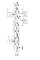
本発明を適用した画像記録再生装置の構成を図1に示す。この図1に示した画像記録再生装置は、IEEE(The International of Electrical and Electronics Engineers,Inc.)1394ハイ・パフォーマンス・シリアル・バスによるデジタル画像信号の同期・非同期通信が可能なDVCRに本発明を適用したもので、ベースバンド信号処理部1に接続されたブロッキング・シャフリング/デブロッキング・デシャフリング処理部2、このブロッキング・シャフリング/デブロッキング・デシャフリング処理部2に接続されたランダムアクセスメモリ(RAM:Random Access Memory)3及びDCT/逆DCT演算処理部4、このDCT/逆DCT演算処理部4に接続された量子化/逆量子化処理部5、この量子化/逆量子化処理部5に接続されたフレーミング/デフレーミング処理部6、このフレーミング/デフレーミング処理部6に接続されたデシャフリング/シャフリング処理部7、このデシャフリング/シャフリング処理部7に接続されたランダムアクセスメモリ(RAM:Random Access Memory)8、オーディオインターフェース9、IEEE1394インターフェース10及び記録符号化/再生復号化処理部11を備えている。
【0020】
先ず、この画像記録再生装置における記録系の構成及び動作について説明する。
【0021】
すなわち、この画像記録再生装置では、記録時に撮像装置からの画像信号あるいは他の画像入力信号がベースバンド信号処理部1を介してブロッキング・シャフリング/デブロッキング・デシャフリング処理部2に供給され、記録する1フレーム分の画像入力信号がRAM3に蓄えられる。静止画記録モード時には、上記RAM3に1フレーム分の画像入力信号すなわち静止画の画像データが蓄えられると、それ以降、その静止画のフレームの連続画が次段に転送される。
【0022】
上記ブロッキング・シャフリング/デブロッキング・デシャフリング処理部2は、上記RAM上で1フレーム分の画像データを8画素×8画素のブロックに分割し、所定数ブロックを単位としてシャフリング処理を施し、シャフリング処理済みの画像データをDCT/逆DCT演算処理部4に与える。
【0023】
上記DCT/逆DCT演算処理部4は、上記ブロッキング・シャフリング/デブロッキング・デシャフリング処理部2から供給される画像データを離散余弦変換(DCT: Discrete Cosine Transform)処理を施すことにより、上記画像データを8画素×8画素のブロック単位で時間軸上の2次元DCT係数データに変換して、量子化/逆量子化処理部5に供給する。
【0024】
この実施の形態における上記DCT/逆DCT演算処理部4では、動画記録モード時には、従来と同様に、8画素×8画素のブロック単位の画像データから動き検出を行い、フィールド間の差が小さいブロックは8×8のDCTモードで画像データを扱い、フィールド間の差の大きいブロックは2×4×8のDCTモードで画像データを扱う。
【0025】
また、上記量子化/逆量子化処理部5は、上記DCT/逆DCT演算処理部4で時間軸上の2次元DCT係数データに変換された画像データを量子化することにより、圧縮処理を施した画像データを生成する。
【0026】
また、上記フレーミング/デフレーミング処理部6は、上記量子化/逆量子化処理部5から供給される画像データをフレーミングして、上記デシャフリング/シャフリング処理部7に供給する。
【0027】
上記デシャフリング/シャフリング処理部7は、上記フレーミング/デフレーミング処理部6から供給される画像データをRAM8に蓄積し、このRAM8上で上記ブロッキング・シャフリング/デブロッキング・デシャフリング処理部2によるシャフリング処理とは逆のデシャフリング処理を画像データに施す。そして、このデシャフリング/シャフリング処理部7は、上記デシャフリング処理により元の配列に戻した画像データ(Video data)に付加データ(VAUX:Video auxiliary)とともにエラー訂正用のECC(ECC:Error Check and Correction)ブロック単位で外符号(Outer parity)を付加して、記録符号化/再生復号化処理部11に供給する。さらに、このデシャフリング/シャフリング処理部7は、オーディオインターフェース9を介して入力されるオーディオデータもECCブロック単位で外符号を付加して、記録符号化/再生復号化処理部11に供給する。
【0028】
そして、上記記録符号化/再生復号化処理部11は、上記デシャフリング/シャフリング処理部7から供給されるECCブロック単位の画像データやオーディオデータにさらにエラー訂正用の内符号(Inner parity)を付加し、さらに、記録に適した符号化処理を施すことにより記録信号を生成し、この記録信号を図示しない記録/再生部を介してビデオテープに記録する。
【0029】
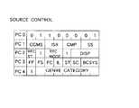
ここで、この画像記録再生装置では、上記画像データ(Video data)とともにECCブロックを構成する付加データVAUXとして、図2に示すように、パック・ヘッダ(PC0)とパック・データ(PC1〜C4)とからなるパック構造のシステム・データを記録する。パック・ヘッダ(PC0)が「0110001」の付加データVAUXは、SOURCE_CONTROLパックであって、そのパック・データ(PC3)によりFF(Frame/Field)フラグ、FS(First/Second)フラグ、FC(Frame change flag)フラグ、IL(Interlace )フラグ、ST(Still-field picture)フラグ、SC(Still camera picture)フラグを与える。上記FFフラグは、1フレーム期間に一方のフィールドのみを2回出力する(FF=0)か1フレーム期間に両方のフィールドを出力する(FF=1)かを示す。また、上記FSフラグは、第1フィールドを出力する(FS=0)か第2フィールドを出力する(FS=1)かを示す。また、上記FCフラグは、現フレームが直前のフレームと同じ画像である(FC=0)か異なる画像である(FC=1)かを示す。また、上記ILフラグは、1フレームを構成する2つのフィールドのデータがインタレースされている(IL=1)か否(IL=0)かを示す。また、上記STフラグは、フレーム内の2つのフィールド間の時間距離が略0秒である(ST=0)か、525−60システム又は625−50システムのおけるフィールド期間に相当している(ST=1)かを示す。さらに、上記SCフラグは、スチルカメラによる画像である(SC=0)か否(SC=1)かを示す。
【0030】
そして、この実施の形態において、上記STフラグは、フレーム内の2つのフィールド間の時間距離が略0秒すなわち静止画をST=0にて示し、525−60システム又は625−50システムのおけるフィールド期間に相当する時間距離の動画をST=1にて示すフラグであるが、静止画記録モードでは、静止画のデータ部分の付加データVAUXのSOURCE_CONTROLパックのSTフラグを「1」にして記録を行う。
【0031】
なお、この画像記録再生装置では、静止画の画像データを上記デシャフリング/シャフリング処理部7のRAM8に蓄積した後、上記ブロッキング・シャフリング/デブロッキング・デシャフリング処理部2の書き込み/読み出しの方向を逆にして、RAM3の画像データを上記ベースバンド信号処理部1に出力することにより、記録時に、記録している静止画を電子ビューファインダや映像出力からモニタすることができる。
【0032】
次に、この画像記録再生装置における再生系の構成及び動作について説明する。
【0033】
すなわち、この画像記録再生装置では、再生時に、図示しない記録/再生部を介してビデオテープから再生された再生信号が記録符号化/再生復号化処理部11に供給される。
【0034】
上記記録符号化/再生復号化処理部11は、記録時の符号化処理に対応する復号化処理を再生信号に施して再生データを生成し、さらに、内符号(Inner parity)によるエラー訂正処理を再生データに施して、エラー訂正処理済みの再生データをデシャフリング/シャフリング処理部7に供給する。
【0035】
上記デシャフリング/シャフリング処理部7は、上記記録符号化/再生復号化処理部11から供給される再生データをRAM8に蓄積し、このRAM8上で外符号(Outer parity)によるエラー訂正処理をECCブロック単位の再生データに施す。上記エラー訂正処理の施された再生データの内の再生オーディオデータは、オーディオインターフェース9を介して出力される。さらに、このデシャフリング/シャフリング処理部7は、記録時における上記ブロッキング・シャフリング/デブロッキング・デシャフリング処理部2と同様なシャフリング処理を再生画像データに施し、シャフリング処理済みの再生画像データをフレーミング/デフレーミング処理部6に供給する。
【0036】
上記フレーミング/デフレーミング処理部6は、上記デシャフリング/シャフリング処理部7から供給される再生画像データをデフレーミングして、量子化/逆量子化処理部5に供給する。ここで、このフレーミング/デフレーミング処理部6により得られる再生画像データは、記録時に上記DCT/逆DCT演算処理部4で時間軸上の2次元DCT係数データに変換された画像データを上記量子化/逆量子化処理部5で量子化したデータに対応している。
【0037】
上記量子化/逆量子化処理部5は、上記フレーミング/デフレーミング処理部6により得られる再生画像データを逆量子化することにより、時間軸上の2次元DCT係数データを再生してDCT/逆DCT演算処理部4に供給する。
【0038】
ここで、この実施の形態における画像記録再生装置では、再生時に、上記画像データ(Video data)とともにECCブロックを構成する付加データVAUXとして記録されている静止画のデータ部分の付加データVAUXのSOURCE_CONTROLパックのSTフラグに基づいて、動作モードが切り換えられ、STフラグが「1」のときに静止画再生モードに切り換えられる。そして、上記フレーミング/デフレーミング処理部6から2次元DCT係数データをDCT/逆DCT演算処理部4に供給する。
【0039】
上記DCT/逆DCT演算処理部4は、図3に示すように、逆DCT演算部41、動き検出部42とORゲート43を備え、上記8×8の時間軸上の2次元DCT係数データを逆DCT演算部41により逆DCT変換して画像データを出力するとともに、そのDCTブロックが動画ブロックであるか静止画ブロックであるかを上記2次元DCT係数データに基づいて検出する所謂動き検出を動き検出部42により行って動き検出フラグMOTをORゲート43を介して出力するようになっている。
【0040】
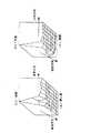
ここで、図4の(a),(b)に静止画と動画のDCT係数の分布状態を示してあるように、動画部分は、フィールド間の差が大きくなるため、静止画部分と比較して垂直方向の高域係数が増加する傾向にある。上記動き検出部42では、この傾向を利用して、各係数の分布から求めた係数の総和やピーク値等を予め設定した閾値と比較することで動き検出を行うことができる。
【0041】
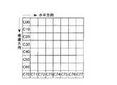
例えば図5に示すようなDCT係数C00〜C77を持つ場合の動き検出は、
【0042】
【数1】
により行う。すなわち、次の3つの条件を同時に満たすときに動きと判定する。
【0044】
(1) C70〜C77までの係数の絶対値の総和が閾値A以上。
【0045】
(2) C70〜C77までの係数で、絶対値の最大差が閾値B以上。
【0046】
(3) C10の絶対値よりC50,C60,C70の絶対値の和が大きい。
【0047】
そして、上記DCT/逆DCT演算処理部4により時間軸上の2次元DCT係数データを逆DCT変換して得られる画像データは、そのDCTブロックが動画ブロックであるか静止画ブロックであるかを示す動き検出フラグMOTとともにブロッキング・シャフリング/デブロッキング・デシャフリング処理部2に供給される。
【0048】
上記ブロッキング・シャフリング/デブロッキング・デシャフリング処理部2は、上記DCT/逆DCT演算処理部4から供給される画像データを1フレーム分の画像データをRAM3に蓄積し、このRAM3上で上記シャフリング/デシャフリング処理部7によるシャフリング処理とは逆のデシャフリング処理を画像データに施す。そして、このデシャフリング/シャフリング処理部7は、上記デシャフリング処理により元の配列に戻した画像データの出力が動き検出フラグMOTにより制御され、静止画ブロック部の画像データはそのままのフレームでベースバンド信号処理部1を介して出力し、動画ブロック部分の画像データは片フィールド×2で上記ベースバンド信号処理部1を介して出力する。
【0049】
このように、この実施の形態における画像記録再生装置では、再生時に、RAMに1フレーム分の画像データを蓄えて、フレーム内での動き量を求め、動き量の小さい部分がそのままフレームで出力し、動きの多い部分は片方のフィールドを2回出力することができ、専用の静止画処理部を必要とすることなく、高画質の静止画を記録再生することができる。
【0050】
なお、動画ブロック部分の画像データを片フィールド×2で出力する際には、図3に示してあるように、上記ブロッキング・シャフリング/デブロッキング・デシャフリング処理部2からスチルフィルタ14を介して動画ブロック部分の画像データを片フィールド×2でベースバンド信号処理部1に出力するようにして、上記スチルフィルタ14でラインフリッカを抑制することによって、更に画質を向上させることができる。
【0051】
ここで、DCT係数による動き検出のみでは、動き検出の漏れすなわち動きがあるにも拘わらず静止画のブロックである検出される虞があるので、さらに、次のようなような処理を行うようにしても良い。
【0052】
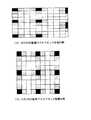
(a) 図6の(A),(B)に網掛け処理を施して示すように、動画ブロックと検出されたDCTブロックを含むマクロブロックは、他のDCTブロックも全て動きブロックとする。
【0053】
(b) 図7の(A),(B)に網掛け処理を施して示すように、動画ブロックと検出されたDCTブロックを含むマクロブロックの上下左右に位置するマクロブロックも全て動きブロックとする。
【0054】
これらの処理は上記ブロッキング・シャフリング/デブロッキング・デシャフリング処理部2で行うことができる。
【0055】
【発明の効果】
以上のように、本発明に係る画像記録再生装置では、2次元配列された所定画素数を単位とする変換ブロック毎に直交変換し、その直交変換係数データを量子化して記録媒体に記録する記録系において、動画記録モードと静止画記録モードの2種類の記録動作モードを有し、上記動画記録モードではフィールド差が小さいブロックは2フィールドから構成されるフレームに対応したDCTブロックで符号化し、フィールド差が大きいブロックは各フィールドに対応したDCTブロックで符号化し、上記静止画記録モードでは、フィールド差に関わらず2フィールドから構成されるフレームに対応したDCTブロックで符号化し、静止画記録モード時に上記量子化した直交変換係数データを記録動作モードを示すフラグとともに記録媒体に記録するので、上記記録媒体から再生した再生信号を逆量子化して得られる直交変換係数データを逆直交変換して再生画像信号を生成するとともに、直交変換係数データに基づいて変換ブロック毎の動き検出を行い、その動き検出結果に基づいて、静止画ブロックと検出された変換ブロックの再生画像信号はフレームで出力し、動画ブロックと検出された変換ブロックの再生画像信号は片フィールドを2回出力する再生系において、上記フラグに応じて静止画再生モードを設定し、静止画再生モードにおいて上記動き検出を行い、その動き検出結果に基づいて、静止画ブロックと検出された変換ブロックの再生画像信号はフレームで出力し、動画ブロックと検出された変換ブロックの再生画像信号は片フィールドを2回出力する処理を行うことができ、これにより、動画記録モードと静止画記録モードの2つ種類の記録動作モードを有する記録系を用いて、専用の静止画処理部を必要とすることなく、高画質の静止画を記録再生することができる。
【0056】
本発明に係る画像記録再生装置では、上記記録系において、静止画記録モード時に上記量子化した直交変換係数データを記録動作モードを示すフラグとともに記録媒体に記録するので、上記再生系において、上記フラグに応じて静止画再生モードを設定し、上記動き検出を行い、その動き検出結果に基づいて、静止画ブロックと検出された変換ブロックの再生画像信号はフレームで出力し、動画ブロックと検出された変換ブロックの再生画像信号は片フィールドを2回出力する処理を行うことができる。これにより、動画記録モードと静止画記録モードの2つ種類の記録動作モードを有する記録系を用いて、専用の静止画処理部を必要とすることなく、高画質の静止画を記録再生することができる。
【0057】
また、本発明に係る画像記録再生装置では、上記再生系において、例えば、逆量子化により得られた直交変換係数データの各係数の分布から算出した値と予め設定した閾値との比較により変換ブロック毎に動き検出を行うことができる。
【0058】
また、本発明に係る画像記録再生装置では、上記再生系において、例えば、上記動き検出の結果に基づいて、動画ブロックと検出された変換ブロックを含むマクロブロックの再生画像信号は片フィールドを2回出力することにより、動き検出の誤りによる画質の低下を防止して、高画質の静止画を記録再生することができる。
【0059】
さらに、本発明に係る画像記録再生装置では、上記再生系において、例えば、上記動き検出の結果に基づいて、動画ブロックと検出された変換ブロックを含むマクロブロックの上下左右に位置するマクロブロックの再生画像信号も片フィールドを2回出力することにより、動き検出の誤りによる画質の低下を確実に防止して、高画質の静止画を記録再生することができる。
【0060】
本発明に係る画像記録再生方法では、2次元配列された所定画素数を単位とする変換ブロック毎に直交変換し、その直交変換係数データを量子化して記録媒体に記録する記録時に、動画記録モードと静止画記録モードの2種類の記録動作モードを有し、上記動画記録モードではフィールド差が小さいブロックは2フィールドから構成されるフレームに対応したDCTブロックで符号化し、フィールド差が大きいブロックは各フィールドに対応したDCTブロックで符号化し、上記静止画記録モードでは、フィールド差に関わらず2フィールドから構成されるフレームに対応したDCTブロックで符号化し、静止画記録モード時に上記量子化した直交変換係数データを記録動作モードを示すフラグとともに記録媒体に記録するので、上記記録媒体から再生した再生信号を逆量子化して得られる直交変換係数データを逆直交変換して再生画像信号を生成するとともに、直交変換係数データに基づいて変換ブロック毎の動き検出を行い、その動き検出結果に基づいて、静止画ブロックと検出された変換ブロックの再生画像信号はフレームで出力し、動画ブロックと検出された変換ブロックの再生画像信号は片フィールドを2回出力する再生時に、上記フラグに応じて静止画再生モードを設定し、静止画再生モードにおいて上記動き検出を行い、その動き検出結果に基づいて、静止画ブロックと検出された変換ブロックの再生画像信号はフレームで出力し、動画ブロックと検出された変換ブロックの再生画像信号は片フィールドを2回出力する処理を行うことができ、これにより、動画記録モードと静止画記録モードの2つ種類の記録動作モードを有する記録系を用いて、専用の静止画処理部を必要とすることなく、高画質の静止画を記録再生することができる。
【0061】
また、本発明に係る画像記録再生方法では、例えば、記録時に、量子化した直交変換係数データを記録モードを示すフラグとともに記録媒体に記録し、再生時に、上記フラグに応じて上記動き検出を行い、その動き検出結果に基づいて、静止画ブロックと検出された変換ブロックの再生画像信号はフレームで出力し、動画ブロックと検出された変換ブロックの再生画像信号は片フィールドを2回出力することにより、複数の記録モードを有する場合にも、専用の静止画処理部を必要とすることなく、高画質の静止画を記録再生することができる。
【0062】
また、本発明に係る画像記録再生方法では、例えば、再生時に逆量子化により得られた直交変換係数データの各係数の分布から算出した値と予め設定した閾値との比較により変換ブロック毎に動き検出を行うことができる。
【0063】
また、本発明に係る画像記録再生方法では、例えば、上記動き検出の結果に基づいて、動画ブロックと検出された変換ブロックを含むマクロブロックの再生画像信号は片フィールドを2回出力することにより、動き検出の誤りによる画質の低下を防止して、高画質の静止画を記録再生することができる。
【0064】
さらに、本発明に係る画像記録再生方法では、例えば、上記動き検出の結果に基づいて、動画ブロックと検出された変換ブロックを含むマクロブロックの上下左右に位置するマクロブロックの再生画像信号も片フィールドを2回出力することにより、動き検出の誤りによる画質の低下を確実に防止して、高画質の静止画を記録再生することができる。
【図面の簡単な説明】
【図1】 本発明に係る画像記録再生装置の構成を示すブロック図である。
【図2】 上記画像記録再生装置において記録再生する画像データとともにECCブロックを構成する付加データVAUXの構成を示す図である。
【図3】 上記画像記録再生装置におけるDCT/逆DCT演算処理部の再生側での構成を示すブロック図である。
【図4】 静止画と動画のDCT係数の分布状態の一例を示す図である。
【図5】 上記DCT/逆DCT演算処理部における動き検出部で動き検出に用いるDCT係数の一例を示す図である。
【図6】 上記画像記録再生装置で記録再生する画像データのマクロブロックを示す図である。
【図7】 マクロブロックの拡張例を示す図である。
【符号の説明】
1 ベースバンド信号処理部、2 ブロッキング・シャフリング/デブロッキング・デシャフリング処理部、3 RAM、4 DCT/逆DCT演算処理部、5 量子化/逆量子化処理部、6 フレーミング/デフレーミング処理部、7 デシャフリング/シャフリング処理部、8 RAM、9 オーディオインターフェース、10 IEEE1394インターフェース、11 記録符号化/再生復号化処理部[0001]
BACKGROUND OF THE INVENTION
The present invention relates to an image recording / reproducing apparatus and an image recording / reproducing method for recording / reproducing a still image.
[0002]
[Prior art]
Conventionally, in a digital video tape recorder that digitally records / reproduces image data, an image signal from an imaging device or other image input signal is stored in a random access memory (RAM) for one frame in a recording system. Then, the image data for one frame is divided into blocks of 8 pixels × 8 pixels on the RAM and subjected to a shuffling process in units of a predetermined number of blocks, and then subjected to orthogonal transformation such as discrete cosine transform (DCT: Discrete Cosine Transform) ) To quantize the image data for one frame. Then, the compressed image data is framed, and the deshuffling process opposite to the shuffling process is performed on the RAM to return to the original array, and then the outer code and the inner code for error correction are added. In addition, encoding processing suitable for recording is performed and recording is performed on a video tape.
[0003]
In the reproduction system, the reproduction data obtained by subjecting the reproduction signal from the video tape to the decoding process opposite to the above encoding process is subjected to error correction processing on the RAM using the outer code and the inner code. The shuffling process is applied. Further, the reproduction data subjected to the shuffling process is deframed, and then decompressed and inversely orthogonal transformed to perform an expansion process on the reproduction data for one frame. Then, the reproduction data for one frame subjected to the decompression process is subjected to a deshuffling process opposite to the shuffling process on the RAM, and the image data of the original pixel array is reproduced by the deblocking process. Yes.
[0004]
[Problems to be solved by the invention]
By the way, an image signal conforming to a standard television system such as the NTSC (National Television Systems Committee) system or the PAL (Phase Alternation by Line) system is an interlace signal. In the conventional digital video tape recorder as described above, an image input signal is used. Is stored as a still image in the RAM for shuffling processing or deshuffling processing, and the still image is recorded and reproduced as it is as a continuous image of a frame as it is, a portion with a large amount of motion becomes a blur of the field cycle during reproduction.
[0005]
However, if one field × 2 is recorded as one frame so as not to cause the field period blur, the resolution in the vertical direction is lowered.
[0006]
In addition, the image data for one frame is stored in the RAM, the amount of motion in the frame is obtained, the portion with a small amount of motion is output as it is, and the portion with a lot of motion is output twice for one field. By providing a dedicated still image processing unit to the recording system, it is possible to record still images without blurring, and any playback device can reproduce the same high-quality still images. Still image processing unit and a RAM for storing image data for processing by the still image processing unit must be provided in the recording system, and the circuit scale of the recording system becomes enormous.
[0007]
In view of the problems in the conventional digital video tape recorder as described above, the object of the present invention is not to require a dedicated still image processing unit or a RAM for storing image data for processing by the still image processing unit, An object of the present invention is to provide an image recording / reproducing apparatus and an image recording / reproducing method capable of recording / reproducing a high-quality still image.
[0008]
[Means for Solving the Problems]
An image recording / reproducing apparatus according to the present invention includes a recording system for orthogonally transforming each transform block having a predetermined number of pixels arranged in two dimensions, quantizing the orthogonal transform coefficient data, and recording the data on a recording medium, and a recording medium The inverse transform of the orthogonal transformation coefficient data obtained by inverse quantization of the reproduction signal reproduced from the above is performed to generate a reproduction image signal, and motion detection is performed for each transform block based on the orthogonal transformation coefficient data, and the motion detection result The reproduced image signal of the still image block and the detected converted block is output as a frame, and the reproduced image signal of the moving image block and the detected converted block is provided with a playback system that outputs one field twice, and The recording system has two types of recording operation modes, a moving image recording mode and a still image recording mode,In the moving image recording mode, a block with a small field difference is encoded with a DCT block corresponding to a frame composed of two fields, and a block with a large field difference is encoded with a DCT block corresponding to each field. Encoded with a DCT block corresponding to a frame composed of two fields regardless of the field difference, In the still image recording mode, the quantized orthogonal transform coefficient data is recorded on a recording medium together with a flag indicating the recording operation mode, and the reproduction system sets the still image reproduction mode according to the flag, and in the still image reproduction mode, The motion detection is performed, and based on the motion detection result, the playback image signal of the still image block and the detected conversion block is output as a frame, and the playback image signal of the conversion block detected as the moving image block is one field. It is characterized by performing the process of outputting the output twice.
[0010]
In the image recording / reproducing apparatus according to the present invention, the reproduction system includes, for example, a conversion block by comparing a value calculated from the distribution of each coefficient of orthogonal transform coefficient data obtained by inverse quantization with a preset threshold value. Motion detection means for detecting motion is provided for each time.
[0011]
In the image recording / playback apparatus according to the present invention, the playback system may be configured such that, for example, a playback image signal of a macroblock including a moving image block and a detected conversion block is one field based on a detection result by the motion detection means. Process to output twice.
[0012]
Furthermore, in the image recording / playback apparatus according to the present invention, the playback system includes, for example, macroblocks positioned above, below, left, and right of a macroblock including a moving image block and a detected conversion block based on a detection result by the motion detection unit. The reproduced image signal is also processed to output one field twice.
[0015]
Further, in the image recording / reproducing method according to the present invention, for example, a motion is calculated for each transform block by comparing a value calculated from the distribution of each coefficient of orthogonal transform coefficient data obtained by inverse quantization at the time of reproduction with a preset threshold value. Perform detection.
[0016]
In the image recording / reproducing method according to the present invention, for example, based on the result of the motion detection, the reproduced image signal of the macro block including the moving image block and the detected conversion block outputs one field twice.
[0017]
Furthermore, in the image recording / reproducing method according to the present invention, for example, based on the result of the motion detection, the reproduced image signals of the macroblocks located above, below, left and right of the macroblock including the moving image block and the detected conversion block are also one field. Is output twice.
[0018]
DETAILED DESCRIPTION OF THE INVENTION
Hereinafter, embodiments of the present invention will be described in detail with reference to the drawings.
[0019]
A configuration of an image recording / reproducing apparatus to which the present invention is applied is shown in FIG. The image recording / reproducing apparatus shown in FIG. 1 is an DVCR capable of synchronous / asynchronous communication of digital image signals by IEEE (The International of Electrical and Electronics Engineers, Inc.) 1394 high performance serial bus. The block shuffling / deblocking /
[0020]
First, the configuration and operation of a recording system in this image recording / reproducing apparatus will be described.
[0021]
That is, in this image recording / reproducing apparatus, during recording, an image signal from the imaging apparatus or another image input signal is supplied to the blocking / shuffling / deblocking /
[0022]
The blocking / shuffling / deblocking /
[0023]
The DCT / inverse DCT
[0024]
In the DCT / inverse DCT
[0025]
The quantization / inverse
[0026]
The framing /
[0027]
The deshuffling / shuffling processing unit 7 stores the image data supplied from the framing /
[0028]
Then, the recording encoding / reproducing decoding processing unit 11 adds an inner code for error correction to the image data and audio data in units of ECC blocks supplied from the deshuffling / shuffling processing unit 7. Furthermore, a recording signal is generated by performing an encoding process suitable for recording, and this recording signal is recorded on a video tape via a recording / reproducing unit (not shown).
[0029]
In this image recording / reproducing apparatus, as shown in FIG. 2, pack data (PC0) and pack data (PC1 to C4) are added as additional data VAUX that constitutes an ECC block together with the image data (Video data). The system data of the pack structure consisting of The additional data VAUX whose pack header (PC0) is “0110001” is a SOURCE_CONTROL pack, and the FF (Frame / Field) flag, FS (First / Second) flag, FC (Frame change) is based on the pack data (PC3). flag) flag, IL (Interlace) flag, ST (Still-field picture) flag, and SC (Still camera picture) flag. The FF flag indicates whether only one field is output twice in one frame period (FF = 0) or both fields are output in one frame period (FF = 1). The FS flag indicates whether to output the first field (FS = 0) or the second field (FS = 1). The FC flag indicates whether the current frame is the same image as the previous frame (FC = 0) or a different image (FC = 1). The IL flag indicates whether the data of two fields constituting one frame are interlaced (IL = 1) or not (IL = 0). The ST flag corresponds to a field period in which a time distance between two fields in a frame is approximately 0 seconds (ST = 0) or in a 525-60 system or a 625-50 system (ST = 1). Further, the SC flag indicates whether the image is a still camera image (SC = 0) or not (SC = 1).
[0030]
In this embodiment, the ST flag indicates that the time distance between two fields in a frame is approximately 0 seconds, that is, a still image is indicated by ST = 0, and is a field in a 525-60 system or a 625-50 system. A moving image of a time distance corresponding to a period is a flag indicating ST = 1. In the still image recording mode, recording is performed with the ST flag of the SOURCE_CONTROL pack of the additional data VAUX of the data portion of the still image set to “1”. .
[0031]
In this image recording / reproducing apparatus, after the still image data is accumulated in the
[0032]
Next, the configuration and operation of the playback system in this image recording / playback apparatus will be described.
[0033]
That is, in this image recording / reproducing apparatus, at the time of reproduction, a reproduction signal reproduced from the video tape via a recording / reproducing unit (not shown) is supplied to the recording encoding / reproducing decoding processing unit 11.
[0034]
The recording encoding / reproducing decoding processing unit 11 performs decoding processing corresponding to the encoding processing at the time of recording on the reproduction signal to generate reproduction data, and further performs error correction processing by an inner code (Inner parity). The reproduction data is subjected to error correction processing and supplied to the deshuffling / shuffling processing unit 7.
[0035]
The deshuffling / shuffling processing unit 7 accumulates the reproduction data supplied from the recording encoding / reproduction decoding processing unit 11 in the
[0036]
The framing /
[0037]
The quantization / inverse
[0038]
Here, in the image recording / reproducing apparatus in this embodiment, during reproduction, the SOURCE_CONTROL pack of the additional data VAUX of the data portion of the still image recorded as the additional data VAUX constituting the ECC block together with the image data (Video data). Based on the ST flag, the operation mode is switched, and when the ST flag is “1”, the still image reproduction mode is switched. Then, the two-dimensional DCT coefficient data is supplied from the framing /
[0039]
As shown in FIG. 3, the DCT / inverse DCT
[0040]
Here, as shown in FIGS. 4A and 4B, the distribution state of the DCT coefficients of the still image and the moving image, the difference between the fields becomes large, so the moving image portion is compared with the still image portion. Therefore, the vertical high frequency coefficient tends to increase. The
[0041]
For example, the DCT coefficient C as shown in FIG.00 ~ C77 If you have motion detection,
[0042]
[Expression 1]
To do. That is, the movement is determined when the following three conditions are satisfied simultaneously.
[0044]
(1) C70 ~ C77 The sum of the absolute values of the coefficients up to is threshold A or higher.
[0045]
(2) C70 ~ C77 The maximum difference in absolute values is greater than or equal to the threshold value B.
[0046]
(3) CTen From the absolute value of C50 , C60 , C70 The sum of absolute values of is large.
[0047]
The image data obtained by inverse DCT transforming the two-dimensional DCT coefficient data on the time axis by the DCT / inverse DCT
[0048]
The blocking / shuffling / deblocking /
[0049]
As described above, in the image recording / reproducing apparatus in this embodiment, at the time of reproduction, image data for one frame is stored in the RAM, the amount of motion in the frame is obtained, and the portion with the small amount of motion is output as it is in the frame. For a portion with a lot of movement, one field can be output twice, and a high-quality still image can be recorded and reproduced without requiring a dedicated still image processing unit.
[0050]
When the image data of the moving image block portion is output in one field × 2, as shown in FIG. 3, the moving image block image is transferred from the blocking / shuffling / deblocking /
[0051]
Here, only the motion detection based on the DCT coefficient may cause a still image block to be detected although there is a motion detection omission, that is, there is motion, so that the following processing is performed. May be.
[0052]
(a) As shown in FIG. 6A and FIG. 6B by performing the shading process, all the other DCT blocks of the macro block including the moving image block and the detected DCT block are also motion blocks.
[0053]
(b) As shown in FIG. 7A and FIG. 7B by performing a shading process, all macroblocks positioned on the top, bottom, left, and right of the macroblock including the moving image block and the detected DCT block are also motion blocks. .
[0054]
These processes can be performed by the blocking / shuffling / deblocking /
[0055]
【The invention's effect】
As described above, the image recording / reproducing apparatus according to the present invention.Then, a two-dimensional array Orthogonal transform is performed for each transform block with the predetermined number of pixels as a unit, and the orthogonal transform coefficient data is quantized to a recording medium.In a recording system for recording, there are two types of recording operation modes, a moving image recording mode and a still image recording mode. In the moving image recording mode, a block with a small field difference is coded by a DCT block corresponding to a frame composed of two fields. A block with a large field difference is encoded with a DCT block corresponding to each field. In the still image recording mode, a block is encoded with a DCT block corresponding to a frame composed of two fields regardless of the field difference. Since the quantized orthogonal transform coefficient data in the mode is recorded on a recording medium together with a flag indicating the recording operation mode, The orthogonal transform coefficient data obtained by inverse quantization of the reproduction signal reproduced from the recording medium is inversely orthogonal transformed to generate a reproduced image signal, and the motion is detected for each transform block based on the orthogonal transform coefficient data. Based on the detection result, the reproduced image signal of the still image block and the detected converted block is output as a frame, and the reproduced image signal of the converted block detected as the moving image block is output one field twice.In the playback system, the still image playback mode is set according to the flag, the motion detection is performed in the still image playback mode, and based on the motion detection result, the playback image signal of the detected block and the converted block is It is possible to perform a process of outputting one field twice for the reproduced image signal of the converted block detected as a moving image block, which is output in a frame, and thereby, two kinds of recording operations of a moving image recording mode and a still image recording mode. Using a recording system with mode, High-quality still images can be recorded and reproduced without requiring a dedicated still image processing unit.
[0056]
In the image recording / reproducing apparatus according to the present invention, in the recording system, the quantized orthogonal transform coefficient data is recorded on a recording medium together with a flag indicating a recording operation mode in the still image recording mode. The still image playback mode is set according to the motion detection, and the motion detection is performed. Based on the motion detection result, the playback image signal of the still image block and the detected conversion block is output as a frame, and the motion image block is detected. The reproduced image signal of the conversion block can be processed to output one field twice. As a result, a high-quality still image can be recorded and reproduced using a recording system having two types of recording operation modes, ie, a moving image recording mode and a still image recording mode, without requiring a dedicated still image processing unit. Can do.
[0057]
In the image recording / playback apparatus according to the present invention, in the playback system, for example, a transform block is obtained by comparing a value calculated from the distribution of each coefficient of orthogonal transform coefficient data obtained by inverse quantization with a preset threshold value. Motion detection can be performed every time.
[0058]
In the image recording / playback apparatus according to the present invention, in the playback system, for example, based on the result of the motion detection, a playback image signal of a macroblock including a moving image block and a detected conversion block is subjected to one field twice. By outputting, it is possible to prevent deterioration in image quality due to motion detection errors and to record and reproduce high-quality still images.
[0059]
Furthermore, in the image recording / playback apparatus according to the present invention, in the playback system, for example, playback of macroblocks located above, below, left, and right of a macroblock including a moving image block and a detected conversion block based on the result of motion detection. By outputting one field twice for the image signal, it is possible to reliably prevent a deterioration in image quality due to an error in motion detection and to record and reproduce a high-quality still image.
[0060]
Image recording / reproducing method according to the present inventionThen, a two-dimensional array Orthogonal transform is performed for each transform block with the predetermined number of pixels as a unit, and the orthogonal transform coefficient data is quantized to a recording medium.At the time of recording, there are two types of recording operation modes, a moving image recording mode and a still image recording mode. In the moving image recording mode, a block with a small field difference is encoded with a DCT block corresponding to a frame composed of two fields. A block having a large field difference is encoded by a DCT block corresponding to each field. In the still image recording mode, the block is encoded by a DCT block corresponding to a frame composed of two fields regardless of the field difference. Sometimes the quantized orthogonal transform coefficient data is recorded on a recording medium together with a flag indicating a recording operation mode. The orthogonal transform coefficient data obtained by inverse quantization of the reproduction signal reproduced from the recording medium is inversely orthogonal transformed to generate a reproduced image signal, and the motion is detected for each transform block based on the orthogonal transform coefficient data. Based on the detection result, the reproduced image signal of the still image block and the detected converted block is output as a frame, and the reproduced image signal of the converted block detected as the moving image block is output one field twice.During playback, the still image playback mode is set according to the flag, the motion detection is performed in the still image playback mode, and based on the motion detection result, the playback image signal of the still image block and the detected conversion block is a frame. Can be processed to output a single field twice for the reproduced image signal of the converted block detected as a moving image block, so that two types of recording operation modes, a moving image recording mode and a still image recording mode, can be performed. Using a recording system having High-quality still images can be recorded and reproduced without requiring a dedicated still image processing unit.
[0061]
In the image recording / reproducing method according to the present invention, for example, the quantized orthogonal transform coefficient data is recorded on a recording medium together with a flag indicating a recording mode at the time of recording, and the motion detection is performed according to the flag at the time of reproduction. Based on the motion detection result, the reproduced image signal of the still image block and the detected converted block is output as a frame, and the reproduced image signal of the converted block detected as the moving image block is output by one field twice. Even when a plurality of recording modes are provided, a high-quality still image can be recorded and reproduced without requiring a dedicated still image processing unit.
[0062]
Further, in the image recording / reproducing method according to the present invention, for example, a motion is calculated for each transform block by comparing a value calculated from the distribution of each coefficient of orthogonal transform coefficient data obtained by inverse quantization at the time of reproduction with a preset threshold value. Detection can be performed.
[0063]
Further, in the image recording / reproducing method according to the present invention, for example, based on the result of the motion detection, the reproduced image signal of the macro block including the moving image block and the detected conversion block outputs one field twice, It is possible to prevent a deterioration in image quality due to a motion detection error and to record and reproduce a high-quality still image.
[0064]
Furthermore, in the image recording / reproducing method according to the present invention, for example, based on the result of the motion detection, reproduced image signals of macroblocks positioned above, below, left, and right of the macroblock including the moving image block and the detected conversion block are also one field. Is output twice, so that a drop in image quality due to an error in motion detection can be reliably prevented, and a high-quality still image can be recorded and reproduced.
[Brief description of the drawings]
FIG. 1 is a block diagram showing a configuration of an image recording / reproducing apparatus according to the present invention.
FIG. 2 is a diagram showing a configuration of additional data VAUX that constitutes an ECC block together with image data to be recorded / reproduced in the image recording / reproducing apparatus.
FIG. 3 is a block diagram showing a configuration on a reproduction side of a DCT / inverse DCT arithmetic processing unit in the image recording / reproducing apparatus.
FIG. 4 is a diagram illustrating an example of a distribution state of DCT coefficients of a still image and a moving image.
FIG. 5 is a diagram illustrating an example of DCT coefficients used for motion detection by a motion detection unit in the DCT / inverse DCT calculation processing unit.
FIG. 6 is a diagram illustrating a macroblock of image data recorded and reproduced by the image recording / reproducing apparatus.
FIG. 7 is a diagram illustrating an example of macroblock expansion.
[Explanation of symbols]
1 baseband signal processing unit, 2 blocking shuffling / deblocking deshuffling processing unit, 3 RAM, 4 DCT / inverse DCT arithmetic processing unit, 5 quantization / inverse quantization processing unit, 6 framing / deframing processing unit, 7 Deshuffling / shuffling processing unit, 8 RAM, 9 audio interface, 10 IEEE1394 interface, 11 recording encoding / playback decoding processing unit
Claims (8)
Translated fromJapanese記録媒体から再生した再生信号を逆量子化して得られる直交変換係数データを逆直交変換して再生画像信号を生成するとともに、直交変換係数データに基づいて変換ブロック毎の動き検出を行い、その動き検出結果に基づいて、静止画ブロックと検出された変換ブロックの再生画像信号はフレームで出力し、動画ブロックと検出された変換ブロックの再生画像信号は片フィールドを2回出力する再生系とを備え、
上記記録系は、動画記録モードと静止画記録モードの2種類の記録動作モードを有し、上記動画記録モードではフィールド差が小さいブロックは2フィールドから構成されるフレームに対応したDCTブロックで符号化し、フィールド差が大きいブロックは各フィールドに対応したDCTブロックで符号化し、上記静止画記録モードでは、フィールド差に関わらず2フィールドから構成されるフレームに対応したDCTブロックで符号化し、静止画記録モード時に上記量子化した直交変換係数データを記録動作モードを示すフラグとともに記録媒体に記録し、
上記再生系は、上記フラグに応じて静止画再生モードを設定し、静止画再生モードにおいて上記動き検出を行い、その動き検出結果に基づいて、静止画ブロックと検出された変換ブロックの再生画像信号はフレームで出力し、動画ブロックと検出された変換ブロックの再生画像信号は片フィールドを2回出力する処理を行うことを特徴とする画像記録再生装置。A recording system for performing orthogonal transform for each transform block having a predetermined number of pixels arranged in a two-dimensional array, quantizing the orthogonal transform coefficient data, and recording it on a recording medium;
The orthogonal transform coefficient data obtained by inverse quantization of the reproduction signal reproduced from the recording medium is inversely orthogonal transformed to generate a reproduced image signal, and the motion is detected for each transform block based on the orthogonal transform coefficient data. Based on the detection result, the reproduction image signal of the still image block and the detected conversion block is output in a frame, and the reproduction image signal of the moving image block and the detected conversion block is provided with a reproduction system that outputs one field twice. ,
The recording system has two types of recording operation modes, a moving image recording mode and a still image recording mode. In the moving image recording mode, a block with a small field difference is encoded with a DCT block corresponding to a frame composed of two fields. A block having a large field difference is encoded by a DCT block corresponding to each field. In the still image recording mode, the block is encoded by a DCT block corresponding to a frame composed of two fields regardless of the field difference. Sometimes the quantized orthogonal transform coefficient data is recorded on a recording medium together with a flag indicating a recording operation mode,
The playback system sets the still image playback mode according to the flag, performs the motion detection in the still image playback mode, and based on the motion detection result, the playback image signal of the still image block and the detected conversion block Is an image recording / reproducing apparatus that performs a process of outputting one field twice for a reproduced image signal of a converted block detected as a moving image block.
上記動き検出手段は、直交変換係数データの所定垂直方向高域係数の絶対値の最大差及び前記絶対値の総和が大きく、且つ前記直交変換係数データの同一水平周波数において所定垂直方向高域係数の絶対値の和が所定垂直方向低域係数の絶対値より大きいとき、前記変換ブロックを動画ブロックとして検出することを特徴とする請求項1記載の画像記録再生装置。The reproduction system includes motion detection means for performing motion detection for each transform block by comparing a value calculated from the distribution of each coefficient of orthogonal transform coefficient data obtained by inverse quantization and a preset threshold value,
The motion detection means has a largemaximum difference between the absolute valuesof the predetermined vertical high frequency coefficients of the orthogonal transform coefficient data and the sum of the absolute values, and the predetermined vertical high frequency coefficients at the same horizontal frequency of the orthogonal transform coefficient data. 2. The image recording / reproducing apparatus according to claim 1, wherein whenthe sum of absolute values islarger than an absolute value of a predetermined vertical low frequency coefficient, the converted block is detected as a moving image block.
ことを特徴とする請求項2記載の画像記録再生装置。The reproduction system performs a process of outputting a single field twice for a reproduction image signal of a macro block including a moving image block and a detected conversion block based on a detection result by the motion detection unit. 2. The image recording / reproducing apparatus according to 2.
ことを特徴とする請求項3記載の画像記録再生装置。Based on the detection result by the motion detecting means, the reproduction image signal of the macro block located above, below, left and right of the macro block including the moving image block and the detected conversion block is also processed to output one field twice. The image recording / reproducing apparatus according to claim 3.
再生時には、記録媒体から再生した再生信号を逆量子化して得られる直交変換係数データを逆直交変換して再生画像信号を生成するとともに、直交変換係数データに基づいて変換ブロック毎の動き検出を行い、その動き検出結果に基づいて、静止画ブロックと検出された変換ブロックの再生画像信号はフレームで出力し、動画ブロックと検出された変換ブロックの再生画像信号は片フィールドを2回出力する画像記録再生方法であって、
上記記録時には、動画記録モードと静止画記録モードの2種類の記録動作モードを有し、上記動画記録モードではフィールド差が小さいブロックは2フィールドから構成されるフレームに対応したDCTブロックで符号化し、フィールド差が大きいブロックは各フィールドに対応したDCTブロックで符号化し、上記静止画記録モードでは、フィールド差に関わらず2フィールドから構成されるフレームに対応したDCTブロックで符号化し、静止画記録モード時に上記量子化した直交変換係数データを記録動作モードを示すフラグとともに記録媒体に記録し、
上記再生時には、上記フラグに応じて静止画再生モードを設定し、静止画再生モードにおいて上記動き検出を行い、その動き検出結果に基づいて、静止画ブロックと検出された変換ブロックの再生画像信号はフレームで出力し、動画ブロックと検出された変換ブロックの再生画像信号は片フィールドを2回出力することを特徴とする画像記録再生方法。At the time of recording, orthogonal transform is performed for each transform block having a predetermined number of pixels arranged two-dimensionally, the orthogonal transform coefficient data is quantized and recorded on a recording medium,
During playback, the orthogonal transform coefficient data obtained by dequantizing the playback signal reproduced from the recording medium is subjected to inverse orthogonal transform to generate a playback image signal, and motion detection is performed for each transform block based on the orthogonal transform coefficient data. Based on the motion detection result, the reproduced image signal of the still image block and the detected converted block is output in a frame, and the reproduced image signal of the detected block of the moving image block is output one field twice. A playback method,
At the time of the recording, there are two kinds of recording operation modes of a moving image recording mode and a still image recording mode. In the moving image recording mode, a block with a small field difference is encoded with a DCT block corresponding to a frame composed of two fields, A block with a large field difference is encoded with a DCT block corresponding to each field. In the still image recording mode, the block is encoded with a DCT block corresponding to a frame composed of two fields regardless of the field difference. The quantized orthogonal transform coefficient data is recorded on a recording medium together with a flag indicating a recording operation mode,
At the time of the playback, the still image playback mode is set according to the flag, the motion detection is performed in the still image playback mode, and based on the motion detection result, the playback image signal of the conversion block detected as the still image block is An image recording / reproducing method, characterized in that one field is output twice as a reproduced image signal of a converted block detected as a moving image block and output as a frame.
ことを特徴とする請求項6記載の画像記録再生方法。The image recording / reproducing method according to claim 6, wherein a reproduced image signal of a macro block including a moving image block and a detected conversion block is output one field twice based on a result of the motion detection.
ことを特徴とする請求項7記載の画像記録再生方法。8. The reproduction image signal of the macro block located above, below, left and right of the macro block including the moving image block and the detected conversion block based on the result of the motion detection also outputs one field twice. Image recording and playback method.
Priority Applications (3)
| Application Number | Priority Date | Filing Date | Title |
|---|---|---|---|
| JP34423896AJP4215835B2 (en) | 1996-12-24 | 1996-12-24 | Image recording / reproducing apparatus and image recording / reproducing method |
| US08/991,357US6175685B1 (en) | 1996-12-24 | 1997-12-16 | Recording/reproducing of video signals, with video signals played back as a frame or a twice-outputted single-field depending on whether the recorded signals are directed as still or moving pictures |
| KR1019970073110AKR100511694B1 (en) | 1996-12-24 | 1997-12-24 | Image recording and reproducing apparatus and image recording reproducing method |
Applications Claiming Priority (1)
| Application Number | Priority Date | Filing Date | Title |
|---|---|---|---|
| JP34423896AJP4215835B2 (en) | 1996-12-24 | 1996-12-24 | Image recording / reproducing apparatus and image recording / reproducing method |
Publications (2)
| Publication Number | Publication Date |
|---|---|
| JPH10191250A JPH10191250A (en) | 1998-07-21 |
| JP4215835B2true JP4215835B2 (en) | 2009-01-28 |
Family
ID=18367701
Family Applications (1)
| Application Number | Title | Priority Date | Filing Date |
|---|---|---|---|
| JP34423896AExpired - Fee RelatedJP4215835B2 (en) | 1996-12-24 | 1996-12-24 | Image recording / reproducing apparatus and image recording / reproducing method |
Country Status (3)
| Country | Link |
|---|---|
| US (1) | US6175685B1 (en) |
| JP (1) | JP4215835B2 (en) |
| KR (1) | KR100511694B1 (en) |
Families Citing this family (3)
| Publication number | Priority date | Publication date | Assignee | Title |
|---|---|---|---|---|
| JP4000543B2 (en)* | 1998-08-03 | 2007-10-31 | ソニー株式会社 | Signal processing apparatus and signal processing method |
| KR100686141B1 (en)* | 2005-01-21 | 2007-02-23 | 엘지전자 주식회사 | Deblocking filter and filtering method of mobile broadcast receiver |
| KR101660772B1 (en) | 2014-12-01 | 2016-09-28 | 주식회사 포스코 | Top nozzle and method for removing molten metal crust using the same |
Family Cites Families (7)
| Publication number | Priority date | Publication date | Assignee | Title |
|---|---|---|---|---|
| JPH04278262A (en)* | 1991-03-05 | 1992-10-02 | Sony Corp | Digital signal recorder/reproducer |
| JPH0591336A (en)* | 1991-09-30 | 1993-04-09 | Hitachi Ltd | Still image recording / reproducing apparatus and still image recording / reproducing system |
| JPH05111008A (en)* | 1991-10-15 | 1993-04-30 | Sony Corp | Information transmitting equipment and information receiving equipment |
| JPH05176294A (en)* | 1991-12-25 | 1993-07-13 | Ricoh Co Ltd | Digital electronic still camera and image reproducing method |
| JPH05176171A (en)* | 1991-12-25 | 1993-07-13 | Ricoh Co Ltd | Image data compression method and apparatus |
| JPH0779449A (en)* | 1993-09-06 | 1995-03-20 | Sony Corp | Vtr device |
| JP3297775B2 (en)* | 1994-04-07 | 2002-07-02 | ソニー株式会社 | Video data recording device and video data reproducing device |
- 1996
- 1996-12-24JPJP34423896Apatent/JP4215835B2/ennot_activeExpired - Fee Related
- 1997
- 1997-12-16USUS08/991,357patent/US6175685B1/ennot_activeExpired - Lifetime
- 1997-12-24KRKR1019970073110Apatent/KR100511694B1/ennot_activeExpired - Fee Related
Also Published As
| Publication number | Publication date |
|---|---|
| KR100511694B1 (en) | 2005-11-08 |
| KR19980064553A (en) | 1998-10-07 |
| US6175685B1 (en) | 2001-01-16 |
| JPH10191250A (en) | 1998-07-21 |
Similar Documents
| Publication | Publication Date | Title |
|---|---|---|
| KR100231186B1 (en) | Quantization Noise Reduction Method and Image Data Decoding Device Generated During Image Data Decoding Process | |
| JPH0818979A (en) | Image processing device | |
| JPH1127675A (en) | Data compressor and compressed data processing method | |
| JP4215835B2 (en) | Image recording / reproducing apparatus and image recording / reproducing method | |
| EP0891104A2 (en) | Digital signal recording apparatus | |
| JP2002521884A (en) | HDTV signal recording and editing | |
| JP3785711B2 (en) | Image reproducing apparatus and image reproducing method | |
| JPH08205066A (en) | Image forming apparatus and system | |
| JP2007134755A (en) | Moving picture encoding apparatus and image recording / reproducing apparatus | |
| JP3164056B2 (en) | Moving image encoding / decoding device, moving image encoding / decoding method, and moving image code recording medium | |
| JP3564087B2 (en) | Video recording and playback device | |
| JP3687458B2 (en) | Compression decoding method and compression decoding apparatus | |
| JP3501505B2 (en) | Image forming apparatus and image processing apparatus | |
| JP3288134B2 (en) | Camera integrated video recording device | |
| JP3619250B2 (en) | Camera-integrated image recording / playback device | |
| US6233281B1 (en) | Video signal processing apparatus, and video signal processing method | |
| JP3297775B2 (en) | Video data recording device and video data reproducing device | |
| JP2947034B2 (en) | Encoding device | |
| JP3769001B2 (en) | Monitor type imaging device | |
| JP3526272B2 (en) | Image processing device | |
| JP3060501B2 (en) | Video signal transmission device | |
| JP3679802B2 (en) | Imaging device | |
| JP3809458B2 (en) | Monitor integrated imaging device | |
| JP3679803B2 (en) | Image recording / playback device | |
| JPH05328396A (en) | Picture encoding device |
Legal Events
| Date | Code | Title | Description |
|---|---|---|---|
| A977 | Report on retrieval | Free format text:JAPANESE INTERMEDIATE CODE: A971007 Effective date:20050315 | |
| A131 | Notification of reasons for refusal | Free format text:JAPANESE INTERMEDIATE CODE: A131 Effective date:20050412 | |
| A521 | Written amendment | Free format text:JAPANESE INTERMEDIATE CODE: A523 Effective date:20050613 | |
| A02 | Decision of refusal | Free format text:JAPANESE INTERMEDIATE CODE: A02 Effective date:20060228 | |
| A521 | Written amendment | Free format text:JAPANESE INTERMEDIATE CODE: A523 Effective date:20060501 | |
| A911 | Transfer to examiner for re-examination before appeal (zenchi) | Free format text:JAPANESE INTERMEDIATE CODE: A911 Effective date:20060518 | |
| A912 | Re-examination (zenchi) completed and case transferred to appeal board | Free format text:JAPANESE INTERMEDIATE CODE: A912 Effective date:20060728 | |
| RD04 | Notification of resignation of power of attorney | Free format text:JAPANESE INTERMEDIATE CODE: A7424 Effective date:20071203 | |
| A521 | Written amendment | Free format text:JAPANESE INTERMEDIATE CODE: A523 Effective date:20080908 | |
| A01 | Written decision to grant a patent or to grant a registration (utility model) | Free format text:JAPANESE INTERMEDIATE CODE: A01 | |
| A61 | First payment of annual fees (during grant procedure) | Free format text:JAPANESE INTERMEDIATE CODE: A61 Effective date:20081105 | |
| FPAY | Renewal fee payment (event date is renewal date of database) | Free format text:PAYMENT UNTIL: 20111114 Year of fee payment:3 | |
| FPAY | Renewal fee payment (event date is renewal date of database) | Free format text:PAYMENT UNTIL: 20121114 Year of fee payment:4 | |
| LAPS | Cancellation because of no payment of annual fees |