JP4214399B2 - Fixing structure using a pair of screw parts and antenna device using the same - Google Patents
Fixing structure using a pair of screw parts and antenna device using the sameDownload PDFInfo
- Publication number
- JP4214399B2 JP4214399B2JP2004045945AJP2004045945AJP4214399B2JP 4214399 B2JP4214399 B2JP 4214399B2JP 2004045945 AJP2004045945 AJP 2004045945AJP 2004045945 AJP2004045945 AJP 2004045945AJP 4214399 B2JP4214399 B2JP 4214399B2
- Authority
- JP
- Japan
- Prior art keywords
- fixing
- pair
- screw
- spring
- bottom plate
- Prior art date
- Legal status (The legal status is an assumption and is not a legal conclusion. Google has not performed a legal analysis and makes no representation as to the accuracy of the status listed.)
- Expired - Fee Related
Links
- 239000002184metalSubstances0.000description8
- 238000005520cutting processMethods0.000description2
- 238000010586diagramMethods0.000description2
- 239000000463materialSubstances0.000description2
- 230000002093peripheral effectEffects0.000description2
- 239000011347resinSubstances0.000description2
- 229920005989resinPolymers0.000description2
- 238000005452bendingMethods0.000description1
- 238000004519manufacturing processMethods0.000description1
- 239000007769metal materialSubstances0.000description1
- 238000000465mouldingMethods0.000description1
- 230000010287polarizationEffects0.000description1
- 238000003825pressingMethods0.000description1
- 238000003892spreadingMethods0.000description1
Images


Classifications
- H—ELECTRICITY
- H01—ELECTRIC ELEMENTS
- H01Q—ANTENNAS, i.e. RADIO AERIALS
- H01Q1/00—Details of, or arrangements associated with, antennas
- H01Q1/12—Supports; Mounting means
- H01Q1/1207—Supports; Mounting means for fastening a rigid aerial element
- H01Q1/1214—Supports; Mounting means for fastening a rigid aerial element through a wall
- H—ELECTRICITY
- H01—ELECTRIC ELEMENTS
- H01Q—ANTENNAS, i.e. RADIO AERIALS
- H01Q1/00—Details of, or arrangements associated with, antennas
- H01Q1/27—Adaptation for use in or on movable bodies
- H01Q1/32—Adaptation for use in or on road or rail vehicles
- H01Q1/325—Adaptation for use in or on road or rail vehicles characterised by the location of the antenna on the vehicle
- H01Q1/3275—Adaptation for use in or on road or rail vehicles characterised by the location of the antenna on the vehicle mounted on a horizontal surface of the vehicle, e.g. on roof, hood, trunk
Landscapes
- Engineering & Computer Science (AREA)
- Remote Sensing (AREA)
- Support Of Aerials (AREA)
Description
Translated fromJapanese本発明は、一対のネジ部品を用いて被固定物を固定板に固定する固定構造に関し、特に、デジタルラジオ放送の受信に用いられる自動車用アンテナを自動車の外板に固定するための一対のネジ部品を用いた固定構造に関する。 The present invention relates to a fixing structure for fixing an object to be fixed to a fixing plate using a pair of screw parts, and in particular, a pair of screws for fixing an automobile antenna used for receiving digital radio broadcasts to an outer plate of the automobile. The present invention relates to a fixing structure using parts.
近時、衛星または地上波を受信して、デジタルラジオ放送を聴取可能にしたデジタルラジオ受信機が開発され、米国において実用化されている。このデジタルラジオ受信機は、自動車などの移動局に搭載され、周波数が2.3GHz帯の電波を受信してラジオ放送を聴取することが可能である。すなわち、デジタルラジオ受信機は、モバイル放送を聴取することが可能なラジオ受信機である。デジタルラジオ放送では、受信電波の周波数が2.3GHz帯の電波が使用されるので、そのときの受信波長(共振波長)λは、約128.3mmである。なお、地上波は、衛星波を一旦、地球局で受信した後、周波数を若干シフトし、直線偏波で再送信したものである。 Recently, digital radio receivers that can receive digital radio broadcasts by receiving satellite or terrestrial waves have been developed and put into practical use in the United States. This digital radio receiver is mounted on a mobile station such as an automobile, and can receive radio waves by receiving radio waves having a frequency of 2.3 GHz. That is, the digital radio receiver is a radio receiver capable of listening to mobile broadcasts. In digital radio broadcasting, a radio wave having a frequency of a reception radio wave of 2.3 GHz is used, and the reception wavelength (resonance wavelength) λ at that time is about 128.3 mm. Note that the terrestrial wave is a signal that is received by the earth station once after the satellite wave is received, and then retransmitted by linear polarization with a slight shift in frequency.
このように、デジタルラジオ放送では、2.3GHz帯の電波が使用されるので、それを受信するアンテナは、室外に設置しなければならない。したがって、デジタルラジオ受信機を自動車に搭載する場合には、そのアンテナを自動車の屋根に取り付けなければならない。 As described above, since radio waves in the 2.3 GHz band are used in digital radio broadcasting, an antenna that receives the radio waves must be installed outdoors. Therefore, when a digital radio receiver is mounted on a vehicle, the antenna must be attached to the roof of the vehicle.
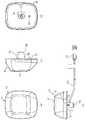
図1(a)乃至図1(d)は、ケーブル20が接続された自動車用アンテナ(以下、アンテナと呼ぶ)10を示している。図2は、アンテナ10を自動車の屋根(固定板)40に固定する状態を示している。 FIGS. 1A to 1D show an automobile antenna (hereinafter referred to as an antenna) 10 to which a
この種のアンテナ10は、小型ドーム型のケース(被固定物)11にアンテナ素子(図示せず)を収容してなる。そして、ケース11下面の中央には、固定部13が突出形成されている。この固定部13は、アンテナ素子に一端部21の先端21aが接続されたケーブル20を外部へ引き出すためのものであって、自動車の屋根40への固定に利用される。この固定部13には、その底部の内面に雌ネジ(第1のネジ部品)14が設けられている。なお、図1(b)及び図2に示したケーブル20は、同軸ケーブルである。 This type of
このアンテナ10を自動車の屋根40に固定するには、次の作業をする必要がある。詳述すると、先ず、アンテナ10の固定部13に対応する固定用穴41を自動車の屋根40に形成する。引き続いて、その固定用穴41に固定部13を挿入する。 In order to fix the
固定用穴41に固定部13を挿入する際には、固定部13の外面に対向するようにクリップの役目を果たす固定金具(固定部材)15を雌ネジ14に螺合する雄ネジ(第2のネジ部品)16によって組み付け仮固定しておく。そして、固定部13に固定金具15を組み付けた状態で固定用穴41に固定部13を挿入する。これにより、ケース11の一部と固定金具15によって屋根40の一部が挟み付けられ、アンテナ10が自動車の屋根40に仮固定される。 When the
図3は、固定金具15の具体例を自動車の屋根40とともの示している。固定金具15は、雄ネジ16のネジ部が貫通する貫通穴15aが形成されている底板部15bと、底板部15bから底板部15bの上方へ互いに少し開く方向へ延びている一対のバネ部15cとを有している。 FIG. 3 shows a specific example of the
バネ部15cには、互いに対向する側辺の中間部分において側辺から突出している側辺間へ延びているガイド部15eが形成されている。自動車の屋根40に形成される固定用穴41の形状は、自動車用アンテナ10の固定部13が対応する位置における外周囲形状の寸法よりも夫々若干大きい。 The
また、これらの内径及び外径は夫々製造バラツキを有している。ガイド部15eは、固定部13に固定金具15を仮固定する際のガイドとなる部分で、アンテナを固定するために雄ネジ16を締めこんでいった時、バネ部15Cが広がり過ぎるのを防ぐ効果がある。また、固定金具15には、バネ部15cの側辺をガイド部15eから底板部15bへガイド部15fを形成することにより側辺の中間部分に段部15hを有している。段部15hは、底板部15bと平行な部分である。In addition, these inner and outer diameters have manufacturing variations. The
なお、固定用穴41は、底板部15bを挿通可能な穴の寸法を持っている。固定金具15のバネ部15cは、固定用穴41に挿入されたとき固定用穴41の内縁部によって押圧されてバネ部15cが変位することによって固定用穴41に挿入される。固定金具15は、固定用穴41から自動車の屋根40の内側に挿入された後に、ケース11とバネ部15cの上端とによって屋根40の一部を挟む形態で仮固定される。その後、雄ネジ16を締め付けてケース11とバネ部の上端とによって自動車の屋根40にアンテナ10を固定する。 The
なお、アンテナ10は、所定方向に向けて取り付けられる。これは、ケーブル20の引き出し方向が決まっていることや、風圧による影響を抑える必要があること、あるいは、自動車の屋根40の形状とアンテナ10の下面形状との不一致による風雨の侵入を防ぐ必要があることなどによる。 The
自動車用アンテナ10は、所定方向を向くように、アンテナ10の下面に形成されたロケーターピン17と、ロケーターピン17に対応して自動車の屋根40に形成された位置決め用穴32とを備えている。即ち、従来の取り付け構造は、アンテナ10を自動車の屋根40に取り付ける際、固定部13を固定用穴41に、ロケーターピン17を位置決め用穴32に夫々対応させて挿入することにより、自動車用アンテナ10が所定方向を向くようにしている。 The
さらに、ケーブル20の一端部21は、自動車用アンテナ10内に挿入され、ケーブルブッシュ30によって自動車用アンテナ10内に保持されている。一方、ケーブル20の他端部には、図示しないレシーバと接続するためのプラグ22が取り付けられている。アンテナ10が自動車の屋根40に固定された後、ケーブル20を自動車内に設置される受信機へと引き回される。 Furthermore, one
上述したように、上記アンテナ10では、固定金具15が固定用穴41に挿入され、固定用穴41の内縁部によってバネ部15cが押圧されて変位したときに、バネ部15cの中間部分に形成されている段部15fが自動車の屋根40の板面に当たってしまい、固定用穴41に固定金具15が挿入できなくなってしまうという問題点がある。 As described above, in the
そこで、本発明は、固定金具が固定用穴に挿入され、固定用穴の内縁部によってバネ部が押圧されて変位したときに、バネ部が円滑に挿入できるアンテナ装置を提供することを目的とする。 Accordingly, an object of the present invention is to provide an antenna device in which a spring part can be smoothly inserted when a fixing metal fitting is inserted into a fixing hole and the spring part is pressed and displaced by an inner edge part of the fixing hole. To do.
本発明によれば、被固定物(11)の固定部(13)に設けられた第1のネジ部品(14)と、該固定部(13)の外側に設けた固定部材(15)と、第1のネジ部品(14)と対を成す第2のネジ部品(16)とを含み、前記固定部13に前記固定部材(15)を組み付けた状態で前記固定部(13)及び前記固定部材を固定板(40)に形成されている固定用穴(41)に挿入し前記第1及び前記第2のネジ部品を螺合することによって前記被固定物を前記固定板の一部と固定部材とで挟み付け固定する一対のネジ部品を用いた固定構造であって、
前記固定部材(15)は、前記第2のネジ部品(16)のネジ部が貫通する貫通穴(15a)が形成されている底板部(15b)と、該底板部(15b)から一方向へ向かって互いに開くように延びている複数のバネ部(15c)とを有し、前記底板部の周囲寸法が前記固定用穴(41)よりも小さい形状寸法であり、前記底板部上へ延びている複数からなる前記バネ部の少なくとも上部の周囲寸法が前記固定用穴よりも大きい寸法形状であり、前記バネ部(15c)のそれぞれは、周方向でバネ部(15c)の側辺同士が互いに対向しており、対向する一対の前記側辺の前記一方向における中間部分において前記側辺から突出し前記周方向で互いに対向するように一対の前記側辺間へそれぞれ延びているガイド部(15e)と、前記底板部(15b)から前記ガイド部(15)の間の前記側辺を前記周方向に湾曲状に切り欠くことによって形成されている切り欠き部(15f)とを有することを特徴とする一対のネジ部品を用いた固定構造が得られる。According to the present invention, the first screw component (14) provided in the fixing part (13) of the fixed object (11), the fixing member (15) provided outside the fixing part (13), A second screw part (16) paired with the first screw part (14), and the fixing part (13) and the fixing member in a state where the fixing member (15) is assembled to the
The fixing member (15), the bottom plate having a through hole which the screw portion passes through (15a) is formed in the second screw part (16) and (15b),in one direction fromthe bottom plate portion (15b)toward and a plurality of spring portions extends andto open (15c)with each other, a shape smaller dimension than the fixing holegirth (41) of the bottom plate portion, and extendsto the bottom plate portion on A plurality of the spring portions, each of which has at least an upperperipheral dimension larger than the fixing hole, andeach of the spring portions(15c) has a circumferential direction in which the sides of the spring portions (15c) are mutuallyGuide portions (15e) facing each other and extending between the pair of side edges so as to protrude from the side edges atan intermediate portion in theone direction of the pair of facing side edges and toface each other in the circumferential direction. And the bottom plate part The guide portion from 15b) a pair of threaded fastener, characterized in thatit has a cutout portion formed by cutting in a curved shape in the circumferential direction (15f) said side edge between (15) The fixing structure used is obtained.
なお、上記カッコ内の参照符号は、本発明の理解を容易にするために付したものであり、何ら本発明を限定するものではない。 Note that the reference numerals in the parentheses are given for easy understanding of the present invention and do not limit the present invention.
本発明によれば、バネ部の側辺には、底板部から一方向側の中間部分へ湾曲状に切り欠いた切り欠き部が形成されているので、固定用穴の内縁部によってバネ部が押圧されて変位したときに、バネ部が円滑に挿入できる。 According to the present invention, the side portion of the spring portion is formed with a cutout portion that is notched in a curved shape from the bottom plate portion to the intermediate portion on the one direction side, so that the spring portion is formed by the inner edge portion of the fixing hole. When it is pressed and displaced, the spring part can be inserted smoothly.
以下、図面を参照して本発明の実施の形態について詳細に説明する。なお、図1乃至図3によって説明した部分と同じ部分には、同じ符号を付して一部の説明を省略する。 Hereinafter, embodiments of the present invention will be described in detail with reference to the drawings. The same parts as those described with reference to FIGS. 1 to 3 are denoted by the same reference numerals, and a part of the description is omitted.
図4(a)乃至図4(c)は、本発明の一実施の形態に係る一対のネジ部品を用いた固定構造における固定金具(固定部材)15を示している。図5に本発明の一実施の形態に係る一対のネジ部品を用いた固定構造を採用する自動車用アンテナ(以下、アンテナと呼ぶ)を示す。 4 (a) to 4 (c) show a fixing bracket (fixing member) 15 in a fixing structure using a pair of screw parts according to an embodiment of the present invention. FIG. 5 shows an automobile antenna (hereinafter referred to as an antenna) that employs a fixing structure using a pair of screw parts according to an embodiment of the present invention.
なお、図1乃至図4によって説明した一対のネジ部品を用いた固定構造における各部品と同じ部分には、同じ符号を付して一部の説明を省略する。 In addition, the same code | symbol is attached | subjected to the same part as each component in the fixing structure using a pair of screw component demonstrated by FIG. 1 thru | or FIG. 4, and one part description is abbreviate | omitted.
図4(a)乃至図5を参照して、一対のネジ部品を用いた固定構造は、小型ドーム型のケース(被固定物)11の固定部13に設けられた雌ネジ(第1のネジ部品)14と、固定部13の外側で固定部13を被うように設けられている固定金具(固定部材)15と、雌ネジ14と対を成す雄ネジ(第2のネジ部品)16とを有している。Referring to FIGS. 4A to 5, the fixing structure using a pair of screw parts is a female screw (first screw) provided in a fixing
固定金具15は、雄ネジ16のネジ部が貫通する貫通穴15aが形成されている底板部15bと、底板部15bから一方向へ向かって互いに開くように延びている一対のバネ部15cとを有している。The fixing
底板部15bの外周囲寸法は、固定用穴41よりも小さい形状寸法であり、底板部15b上に延びている複数からなるバネ部15cの少なくとも上部の周囲寸法が固定用穴よりも大きい寸法形状となっている。バネ部15cのそれぞれは、貫通穴15aと同心円となるような略円弧状の面を有する。Outer girth of the
バネ部15cのそれぞれは、周方向でバネ部15cの側辺同士が互いに対向しており、対向する一対の側辺の一方向における中間部分において側辺から突出し周方向で互いに対向するように一対の側辺間へそれぞれ延びているガイド部15eと、底板部15bからガイド部15の間のバネ部15cの側辺を周方向に湾曲状に切り欠くことによって形成されている切り欠き部15fとを有する。ガイド部15eは、固定部13に固定金具15を仮固定する際のガイドとなる部分である。Each of the
自動車の屋根40に形成される固定用穴41の形状は、アンテナ10の固定部13が対応する位置における外形形状の寸法よりも夫々若干大きい。即ち、これらの間には夫々クリアランスが存在する。 The shape of the fixing
このアンテナ10を自動車の屋根40に固定するには、先ず、アンテナ10の固定部13に対応する固定用穴41を自動車の屋根40に形成する。引き続いて、その固定用穴41に固定部13を挿入するが、固定用穴41に固定部13を挿入する際には、固定部13に被るように固定金具15を雌ネジ14に螺合する雄ネジ(第2のネジ部品)16によって組み付け仮固定しておく。 In order to fix the
そして、固定部13に固定金具15を組み付けた状態で固定用穴41に固定部13を挿入する。このとき、バネ部15cの側辺には、底板部15bから上方側の中間部分のガイド部15へ向けて湾曲している切り欠き部15fが形成されているので、固定用穴41の内縁部分に切り欠き部15fが当接しつつ円滑に挿入される。これにより、ケース11の一部と固定金具15によって屋根40の一部を挟み付ける方向でアンテナ10が自動車の屋根40に仮固定される。 Then, the fixing
固定部13に固定金具15を仮固定した後は、固定部13に固定金具15を組み付けた状態で第1及び第2のネジ部品14、16を螺合することによってケース11を自動車の屋根40の一部と固定金具15とで挟み付け固定する。 After the fixing
以上、本発明について一実施の形態に即して説明したが、本発明は上記実施の形態に限定されるものではない。 While the present invention has been described with reference to one embodiment, the present invention is not limited to the above embodiment.
例えば、上記実施の形態では、アンテナを自動車の屋根に取り付ける場合について説明したが、アンテナ以外のいかなる被固定物にも適用でき、また、自動車の屋根以外のいかなる固定板にも適用できる。 For example, in the above embodiment, the case where the antenna is attached to the roof of the automobile has been described. However, the present invention can be applied to any fixed object other than the antenna, and can be applied to any fixing plate other than the roof of the automobile.
また、実施の形態においては、固定部材として金属板をプレスにより曲げ加工を施して製作することができる固定金具を採用して説明したが、樹脂材を採用して固定部材を成型することによっても製作できる。要するに、バネ部に弾性を持つようにできるものであれば、金属材料や樹脂材料を採用して製作が可能である。 Further, in the embodiment, the description has been made by adopting the fixing metal fitting that can be manufactured by bending a metal plate by pressing as the fixing member, but also by adopting a resin material and molding the fixing member. Can be produced. In short, any metal material or resin material can be used as long as the spring portion can have elasticity.
10 アンテナ
11 ケース(被固定物)
13 固定部
14 雌ネジ(第1のネジ部品)
15 固定金具(固定部材)
15a 貫通穴
15b 底板部
15c バネ部
15e ガイド部
15f 切り欠き部
16 雄ネジ(第2のネジ部品)
17 ロケーターピン
20 ケーブル
32 位置決め用穴
40 屋根(固定板)
41 固定用穴10
13 Fixing
15 Fixing bracket (fixing member)
15a Through
17
41 Fixing hole
Claims (5)
Translated fromJapanese前記固定部材は、前記第2のネジ部品のネジ部が貫通する貫通穴が形成されている底板部と、該底板部から一方向へ向かって互いに開くように延びている複数のバネ部とを有し、前記底板部の周囲寸法が前記固定用穴よりも小さい形状寸法であり、前記底板部上へ延びている複数からなる前記バネ部の少なくとも上部の周囲寸法が前記固定用穴よりも大きい寸法形状であり、前記バネ部のそれぞれは、周方向でバネ部の側辺同士が互いに対向しており、対向する一対の前記側辺の前記一方向における中間部分において前記側辺から突出し前記周方向で互いに対向するように一対の前記側辺間へそれぞれ延びているガイド部と、前記底板部から前記ガイド部の間の前記側辺を前記周方向に湾曲状に切り欠くことによって形成されている切り欠き部とを有することを特徴とする一対のネジ部品を用いた固定構造。A first screw part provided on a fixed part of an object to be fixed; a fixing member provided outside the fixed part; and a second screw part that forms a pair with the first screw part. In the state where the fixing member is assembled to the fixing member, the fixing portion and the fixing member are inserted into fixing holes formed in a fixing plate, and the first and second screw parts are screwed together to fix the object to be fixed. Is a fixing structure using a pair of screw parts that sandwich and fix between a part of the fixing plate and a fixing member,
The fixing member, the second screw part of the screw portion is a bottom plate portion having a through hole is formed to penetrate, and a plurality of spring portions extendingto open to each other toward fromthe bottom plate portionin one direction has a shape smaller size thangirth the fixing hole of the bottom plate portion, at least the upper portion of thegirth of the spring portion consisting of a plurality of extendingto the bottom plate portion on is greater than the fixing holeEach of the spring parts has a dimensional shape, and thesides of the spring part are opposed to each other in the circumferential direction, and protrudes from the side in an intermediate part in the one direction of the pair of opposed sides. And a guide portion extending between the pair of side edges so as to face each other in the direction, and the side portion between the bottom plate portion and the guide portion is cut out in a curved shape in the circumferential direction. Cutout Fixed structure using a pair of threaded fastener, characterized in thatit comprises and.
Priority Applications (3)
| Application Number | Priority Date | Filing Date | Title |
|---|---|---|---|
| JP2004045945AJP4214399B2 (en) | 2004-02-23 | 2004-02-23 | Fixing structure using a pair of screw parts and antenna device using the same |
| US11/024,634US7256745B2 (en) | 2004-02-23 | 2004-12-29 | Fixing device for fixing an object to a fixing plate and antenna apparatus using the fixing device |
| CN200410104196.5ACN1661856A (en) | 2004-02-23 | 2004-12-30 | Fixing device for fixing an object to a fixing plate and antenna apparatus using the fixing device |
Applications Claiming Priority (1)
| Application Number | Priority Date | Filing Date | Title |
|---|---|---|---|
| JP2004045945AJP4214399B2 (en) | 2004-02-23 | 2004-02-23 | Fixing structure using a pair of screw parts and antenna device using the same |
Publications (2)
| Publication Number | Publication Date |
|---|---|
| JP2005236846A JP2005236846A (en) | 2005-09-02 |
| JP4214399B2true JP4214399B2 (en) | 2009-01-28 |
Family
ID=34858119
Family Applications (1)
| Application Number | Title | Priority Date | Filing Date |
|---|---|---|---|
| JP2004045945AExpired - Fee RelatedJP4214399B2 (en) | 2004-02-23 | 2004-02-23 | Fixing structure using a pair of screw parts and antenna device using the same |
Country Status (3)
| Country | Link |
|---|---|
| US (1) | US7256745B2 (en) |
| JP (1) | JP4214399B2 (en) |
| CN (1) | CN1661856A (en) |
Families Citing this family (30)
| Publication number | Priority date | Publication date | Assignee | Title |
|---|---|---|---|---|
| US7954127B2 (en) | 2002-09-25 | 2011-05-31 | The Directv Group, Inc. | Direct broadcast signal distribution methods |
| JP4214399B2 (en) | 2004-02-23 | 2009-01-28 | ミツミ電機株式会社 | Fixing structure using a pair of screw parts and antenna device using the same |
| JP4488197B2 (en)* | 2004-09-10 | 2010-06-23 | ミツミ電機株式会社 | Antenna device having a fixing structure using a pair of screw parts |
| US7945932B2 (en) | 2005-04-01 | 2011-05-17 | The Directv Group, Inc. | Narrow bandwidth signal delivery system |
| US8024759B2 (en) | 2005-04-01 | 2011-09-20 | The Directv Group, Inc. | Backwards-compatible frequency translation module for satellite video delivery |
| US7987486B2 (en) | 2005-04-01 | 2011-07-26 | The Directv Group, Inc. | System architecture for control and signal distribution on coaxial cable |
| US7900230B2 (en) | 2005-04-01 | 2011-03-01 | The Directv Group, Inc. | Intelligent two-way switching network |
| US7958531B2 (en) | 2005-04-01 | 2011-06-07 | The Directv Group, Inc. | Automatic level control for incoming signals of different signal strengths |
| US7950038B2 (en) | 2005-04-01 | 2011-05-24 | The Directv Group, Inc. | Transponder tuning and mapping |
| US7937732B2 (en) | 2005-09-02 | 2011-05-03 | The Directv Group, Inc. | Network fraud prevention via registration and verification |
| US8789115B2 (en)* | 2005-09-02 | 2014-07-22 | The Directv Group, Inc. | Frequency translation module discovery and configuration |
| US7636067B2 (en)* | 2005-10-12 | 2009-12-22 | The Directv Group, Inc. | Ka/Ku antenna alignment |
| US7609218B2 (en)* | 2005-10-12 | 2009-10-27 | The Directv Group, Inc. | Enhanced back assembly for Ka/Ku ODU |
| US7663543B2 (en)* | 2005-10-12 | 2010-02-16 | The Directv Group, Inc. | Alignment method for multi-satellite consumer receiver antennas |
| US7991348B2 (en)* | 2005-10-12 | 2011-08-02 | The Directv Group, Inc. | Triple band combining approach to satellite signal distribution |
| US20070080887A1 (en)* | 2005-10-12 | 2007-04-12 | Kesse Ho | KA LNB umbrella shade |
| US8515342B2 (en) | 2005-10-12 | 2013-08-20 | The Directv Group, Inc. | Dynamic current sharing in KA/KU LNB design |
| US8019275B2 (en)* | 2005-10-12 | 2011-09-13 | The Directv Group, Inc. | Band upconverter approach to KA/KU signal distribution |
| US9282299B2 (en)* | 2005-10-12 | 2016-03-08 | The Directv Group, Inc. | Single local oscillator sharing in multi-band Ka-band LNBS |
| US8719875B2 (en) | 2006-11-06 | 2014-05-06 | The Directv Group, Inc. | Satellite television IP bitstream generator receiving unit |
| US8712318B2 (en) | 2007-05-29 | 2014-04-29 | The Directv Group, Inc. | Integrated multi-sat LNB and frequency translation module |
| JP4384204B2 (en)* | 2007-06-22 | 2009-12-16 | 豊田鉄工株式会社 | Member mounting structure |
| US8238813B1 (en) | 2007-08-20 | 2012-08-07 | The Directv Group, Inc. | Computationally efficient design for broadcast satellite single wire and/or direct demod interface |
| US9942618B2 (en) | 2007-10-31 | 2018-04-10 | The Directv Group, Inc. | SMATV headend using IP transport stream input and method for operating the same |
| MX2011007027A (en) | 2009-01-06 | 2011-07-20 | Directv Group Inc | Frequency drift estimation for low cost outdoor unit. |
| CN102242755B (en)* | 2010-05-14 | 2015-08-12 | 富瑞精密组件(昆山)有限公司 | Screw connection structure |
| US8299372B2 (en)* | 2010-06-11 | 2012-10-30 | Laird Technologies, Inc. | Antenna universal mount joint connectors |
| CN103682556B (en)* | 2013-11-13 | 2015-12-30 | 南京航空航天大学 | A kind of airborne remote antenna erecting device |
| JP6339880B2 (en)* | 2014-07-07 | 2018-06-06 | 株式会社タチエス | Fixing structure for mounting parts, backboard and vehicle seat |
| US11817623B1 (en) | 2022-05-16 | 2023-11-14 | Verizon Patent And Licensing Inc. | Protective structure for protecting antenna from damage |
Family Cites Families (19)
| Publication number | Priority date | Publication date | Assignee | Title |
|---|---|---|---|---|
| US3120640A (en)* | 1961-09-29 | 1964-02-04 | Lab For Electronics Inc | Casing and support for transmitterreceiver |
| US3729741A (en)* | 1971-04-19 | 1973-04-24 | O Otto | Automobile antenna support |
| US4114159A (en)* | 1976-11-01 | 1978-09-12 | Verini Anthony J | Dual pivot mount assembly for an automobile antenna |
| DE3927529C1 (en) | 1989-08-21 | 1991-03-07 | A. Raymond Kg, 7850 Loerrach, De | |
| JP2581310Y2 (en) | 1992-04-30 | 1998-09-21 | 株式会社ケンウッド | Mounting structure of vehicle-mounted antenna |
| JPH07326914A (en)* | 1994-05-31 | 1995-12-12 | Mitsumi Electric Co Ltd | Antenna unit for car navigator |
| JPH098517A (en)* | 1995-06-20 | 1997-01-10 | Mitsumi Electric Co Ltd | Plane antenna |
| JP2001036315A (en)* | 1999-07-22 | 2001-02-09 | Nippon Antenna Co Ltd | Car antenna |
| US6294740B1 (en)* | 1999-09-20 | 2001-09-25 | Andrew Corporation | Spring clip for a gas tube surge arrestor |
| US6157345A (en)* | 1999-09-24 | 2000-12-05 | Magnadyne Corporation | Antenna assembly and method of installing an antenna |
| US6762727B2 (en) | 2001-10-09 | 2004-07-13 | Tyco Electronics Corporation | Quick-attach, single-sided automotive antenna attachment assembly |
| US7004666B2 (en) | 2001-10-09 | 2006-02-28 | Tyco Electronics Corporation | Quick-attach automotive antenna mounting assembly |
| US7077843B2 (en) | 2002-06-24 | 2006-07-18 | Lanx, Llc | Cervical plate |
| CA2414718C (en)* | 2002-12-17 | 2005-11-22 | Research In Motion Limited | Dual mode antenna system for radio transceiver |
| JP4037335B2 (en) | 2003-07-31 | 2008-01-23 | 株式会社ヨコオ | Antenna mounting device |
| US6930643B2 (en) | 2003-11-03 | 2005-08-16 | Delphi Technologies, Inc. | Antenna module assembly |
| JP4214399B2 (en) | 2004-02-23 | 2009-01-28 | ミツミ電機株式会社 | Fixing structure using a pair of screw parts and antenna device using the same |
| US7038200B2 (en) | 2004-04-28 | 2006-05-02 | Bruker Daltonik Gmbh | Ion cyclotron resonance mass spectrometer |
| JP4488197B2 (en) | 2004-09-10 | 2010-06-23 | ミツミ電機株式会社 | Antenna device having a fixing structure using a pair of screw parts |
- 2004
- 2004-02-23JPJP2004045945Apatent/JP4214399B2/ennot_activeExpired - Fee Related
- 2004-12-29USUS11/024,634patent/US7256745B2/ennot_activeExpired - Lifetime
- 2004-12-30CNCN200410104196.5Apatent/CN1661856A/enactivePending
Also Published As
| Publication number | Publication date |
|---|---|
| JP2005236846A (en) | 2005-09-02 |
| US7256745B2 (en) | 2007-08-14 |
| CN1661856A (en) | 2005-08-31 |
| US20050184923A1 (en) | 2005-08-25 |
Similar Documents
| Publication | Publication Date | Title |
|---|---|---|
| JP4214399B2 (en) | Fixing structure using a pair of screw parts and antenna device using the same | |
| US7580002B2 (en) | Antenna unit with a top cover painted in one of various colors | |
| JP4873143B2 (en) | Antenna device | |
| US10741903B1 (en) | Vehicle antenna device | |
| US6486842B2 (en) | Pivottable connection configuration of retractable roof mounted antenna | |
| JP4849281B2 (en) | Antenna device | |
| JP4807530B2 (en) | Antenna device and antenna waterproof structure | |
| US8081133B2 (en) | Satellite antenna with holder assembly for holding LNBF | |
| US20240097317A1 (en) | An antenna device for a vehicle | |
| US7825341B2 (en) | Antenna device and shield cover thereof | |
| NZ260863A (en) | Uhf antenna, support and coupler mountable on vehicle windscreen | |
| JP4332715B2 (en) | Fixing structure using a pair of screw parts and antenna device including the same | |
| JP4582320B2 (en) | Antenna unit | |
| US20060056911A1 (en) | Fixing device for fixing an object to a fixing plate and antenna apparatus using the fixing device | |
| JPH05167345A (en) | Antenna | |
| JP3101932B2 (en) | antenna | |
| JP2004319898A (en) | Electronic equipment housing and communication equipment | |
| JP2005216809A (en) | Cable bushing attaching method, cable bushing, cable with bushing, and antenna device | |
| JP2009044424A (en) | Sponge member attaching method, sponge member, extension cable with sponge member and antenna device | |
| JPH05235636A (en) | Planar antenna device | |
| JP2014075771A (en) | Antenna device |
Legal Events
| Date | Code | Title | Description |
|---|---|---|---|
| A621 | Written request for application examination | Free format text:JAPANESE INTERMEDIATE CODE: A621 Effective date:20060626 | |
| A977 | Report on retrieval | Free format text:JAPANESE INTERMEDIATE CODE: A971007 Effective date:20080711 | |
| A131 | Notification of reasons for refusal | Free format text:JAPANESE INTERMEDIATE CODE: A131 Effective date:20080716 | |
| A521 | Request for written amendment filed | Free format text:JAPANESE INTERMEDIATE CODE: A523 Effective date:20080912 | |
| TRDD | Decision of grant or rejection written | ||
| A01 | Written decision to grant a patent or to grant a registration (utility model) | Free format text:JAPANESE INTERMEDIATE CODE: A01 Effective date:20081008 | |
| A01 | Written decision to grant a patent or to grant a registration (utility model) | Free format text:JAPANESE INTERMEDIATE CODE: A01 | |
| A61 | First payment of annual fees (during grant procedure) | Free format text:JAPANESE INTERMEDIATE CODE: A61 Effective date:20081021 | |
| R150 | Certificate of patent or registration of utility model | Ref document number:4214399 Country of ref document:JP Free format text:JAPANESE INTERMEDIATE CODE: R150 | |
| FPAY | Renewal fee payment (event date is renewal date of database) | Free format text:PAYMENT UNTIL: 20111114 Year of fee payment:3 | |
| FPAY | Renewal fee payment (event date is renewal date of database) | Free format text:PAYMENT UNTIL: 20111114 Year of fee payment:3 | |
| FPAY | Renewal fee payment (event date is renewal date of database) | Free format text:PAYMENT UNTIL: 20141114 Year of fee payment:6 | |
| R250 | Receipt of annual fees | Free format text:JAPANESE INTERMEDIATE CODE: R250 | |
| R250 | Receipt of annual fees | Free format text:JAPANESE INTERMEDIATE CODE: R250 | |
| LAPS | Cancellation because of no payment of annual fees |