JP4214290B2 - Concrete structure diagnostic apparatus and diagnostic method using the same - Google Patents
Concrete structure diagnostic apparatus and diagnostic method using the sameDownload PDFInfo
- Publication number
- JP4214290B2 JP4214290B2JP2006017831AJP2006017831AJP4214290B2JP 4214290 B2JP4214290 B2JP 4214290B2JP 2006017831 AJP2006017831 AJP 2006017831AJP 2006017831 AJP2006017831 AJP 2006017831AJP 4214290 B2JP4214290 B2JP 4214290B2
- Authority
- JP
- Japan
- Prior art keywords
- concrete structure
- hammer drill
- wave
- drilling
- elastic wave
- Prior art date
- Legal status (The legal status is an assumption and is not a legal conclusion. Google has not performed a legal analysis and makes no representation as to the accuracy of the status listed.)
- Active
Links
- 238000002405diagnostic procedureMethods0.000titledescription8
- 238000005553drillingMethods0.000claimsdescription32
- 238000005259measurementMethods0.000claimsdescription19
- 238000006243chemical reactionMethods0.000claimsdescription16
- 238000000034methodMethods0.000claimsdescription16
- 238000011156evaluationMethods0.000claimsdescription13
- 230000006866deteriorationEffects0.000claimsdescription12
- 239000011159matrix materialSubstances0.000claimsdescription12
- 238000006073displacement reactionMethods0.000claimsdescription8
- 238000003325tomographyMethods0.000claimsdescription7
- 238000012854evaluation processMethods0.000claimsdescription5
- 238000011900installation processMethods0.000claimsdescription3
- 230000005540biological transmissionEffects0.000claimsdescription2
- 230000007547defectEffects0.000description9
- 238000004458analytical methodMethods0.000description6
- 238000004441surface measurementMethods0.000description6
- 238000010586diagramMethods0.000description5
- 230000008439repair processEffects0.000description4
- 238000013480data collectionMethods0.000description3
- 230000005484gravityEffects0.000description3
- 238000001179sorption measurementMethods0.000description3
- 238000009412basement excavationMethods0.000description2
- 230000002950deficientEffects0.000description2
- 238000003745diagnosisMethods0.000description2
- 238000003825pressingMethods0.000description2
- NBPVGUFVMFMDJF-UHFFFAOYSA-NCCC(CC1)C2C1C2CChemical compoundCCC(CC1)C2C1C2CNBPVGUFVMFMDJF-UHFFFAOYSA-N0.000description1
- 230000032683agingEffects0.000description1
- 230000002238attenuated effectEffects0.000description1
- 230000015556catabolic processEffects0.000description1
- 230000007797corrosionEffects0.000description1
- 238000005260corrosionMethods0.000description1
- 238000005336crackingMethods0.000description1
- 238000005520cutting processMethods0.000description1
- 230000006378damageEffects0.000description1
- 238000006731degradation reactionMethods0.000description1
- 238000001514detection methodMethods0.000description1
- 238000009826distributionMethods0.000description1
- 238000005516engineering processMethods0.000description1
- 230000001771impaired effectEffects0.000description1
- 230000010354integrationEffects0.000description1
- 238000012423maintenanceMethods0.000description1
- 239000002245particleSubstances0.000description1
- 230000035515penetrationEffects0.000description1
- 230000000704physical effectEffects0.000description1
- 239000000523sampleSubstances0.000description1
- 239000000126substanceSubstances0.000description1
- 238000012360testing methodMethods0.000description1
- 230000003685thermal hair damageEffects0.000description1
Images


Landscapes
- Investigating Strength Of Materials By Application Of Mechanical Stress (AREA)
- Testing Of Devices, Machine Parts, Or Other Structures Thereof (AREA)
- Investigating Or Analyzing Materials By The Use Of Ultrasonic Waves (AREA)
Description
Translated fromJapanese本発明は、コンクリート構造物の表面劣化と内部欠陥の有無を同時に診断する装置に関する。詳しくはハンマードリルの削孔抵抗指標と、削孔打撃に伴う弾性波の測定を容易に且つ正確に行う装置とそれを用いた診断方法に関する。 The present invention relates to an apparatus for simultaneously diagnosing the presence of surface deterioration and internal defects of a concrete structure. More particularly, the present invention relates to a drilling resistance index of a hammer drill, an apparatus for easily and accurately measuring an elastic wave accompanying drilling and a diagnostic method using the apparatus.
コンクリート構造物においては、凍害、化学的腐食、風化・老化、火災などによりスケーリング・ひび割れ等の表面劣化現象が起こる。従来の維持管理においては、通常コンクリート表面の劣化が顕在化した後に補修が行われていた。 In concrete structures, surface deterioration phenomena such as scaling and cracking occur due to frost damage, chemical corrosion, weathering / aging, fire, and the like. In conventional maintenance, repairs are usually performed after deterioration of the concrete surface becomes obvious.
劣化現象が表面に限定される場合には、劣化部を除去して健全部を露出させて断面修復による補修が行われていた。この場合、劣化部除去が不十分であると構造物の一体化を損ない、さらに構造物内部に潜在的な劣化要因を残してしまう問題が発生する。又、逆に過剰な劣化部除去は、修復コスト高を招く問題があった。このため、除去を要する劣化深さの診断・判定が重要であった。 When the deterioration phenomenon is limited to the surface, the deteriorated portion is removed to expose the healthy portion, and repair by cross-sectional repair has been performed. In this case, if the deteriorated portion is not sufficiently removed, the integration of the structure is impaired, and a problem of leaving a potential deterioration factor inside the structure occurs. On the other hand, removal of an excessively deteriorated part has a problem incurring high repair costs. For this reason, it is important to diagnose and judge the deterioration depth that needs to be removed.
特許文献1はコア貫入反力からコンクリートの深さ方向の強度を求める方法に係る発明であり、また非特許文献1ではコアドリルの電力に基づく切削効率からコンクリート強度を推定する方法に係る提案がなされている。いずれもコアドリルを用いて診断対象のコンクリート構造物に50mm程度の欠損を与えてしまう問題があった。
特許文献2には、ハンマードリルを用いてコンクリート部材の圧縮強度測定装置及び圧縮強度測定方法が開示されている。この発明はハンマードリルを用いるため、コンクリート構造物に対する欠損は小さいものの、一定速度削孔における反力を指標とする方法であるため、反力以外の抵抗指標が考慮されないため、診断が正確に行えない問題があった。また、ハンマードリルの押圧に油圧ジャッキを用いているため装置が高価になる問題があった。
非特許文献2は、一定反力でハンマードリル削孔を行い、回転数、電圧、電流から抵抗指標を求め、コンクリート構造物の火災劣化を評価するものであるが、削孔方向に伴う反力制御が難しい問題があった。 Non-Patent
特許文献3は、坑井掘削中の放出弾性波の三次元粒子運動解析による地下構造評価方法の発明である。この発明では、ドリルビット掘削の弾性波を坑井内に設置した3軸弾波検出器で検出し、直達波・反射波の解析により地下構造を評価するものである。しかし、ハンマードリルから発生する弾性波がコンクリート構造物の内部を伝わる直達波・反射波についての解析は、従来まったく行われていなかった。
また、従来のこれらの技術では、削孔深さに対応したコンクリート構造物の物性評価であったが、削孔深さより深い部分の情報、すなわちコンクリート構造物の内部欠陥(空洞、ジャンカ、打ち継ぎ部など)の検知はなされていなかった。 In addition, in these conventional technologies, the physical properties of the concrete structure corresponding to the drilling depth were evaluated. However, information on a portion deeper than the drilling depth, that is, internal defects (cavity, jumper, jointing) of the concrete structure. Detection).
本発明は、前述の問題に鑑みてなされたもので、評価対象のコンクリート構造物に固定し、一定反力での自動削孔・抵抗指標情報の自動収集ならびに弾性波検出のための加速度計を配置するコンクリート構造物診断装置及びその測定診断方法の提供を課題とする。 The present invention has been made in view of the above-described problems. An accelerometer for fixing automatic drilling / resistance index information with a constant reaction force and detecting an elastic wave is fixed to a concrete structure to be evaluated. It is an object of the present invention to provide a concrete structure diagnostic device to be arranged and a measurement diagnostic method thereof.
本発明のコンクリート構造物診断装置は、評価対象のコンクリート構造物の表面に固定するアンカー部と、該アンカー部背面に垂直に固定された所定長四角柱状のガイドレールと、該ガイドレールの一側に嵌合されたラックギアとからなる装置固定部と、該装置固定部のガイドレールにガイド角穴を挿嵌しガイドレールを前後に摺動可能な装置移動部と、該装置移動部に支持されて振動による打撃とビット刃の回転によりコンクリート構造物に削孔するハンマードリルと、装置移動部に把持・固定された前記ハンマードリルの削孔深さを測定する変位計と、ハンマードリルの回転数を計測するセンサーと、反発硬度/原形波を測定する加速度計と、前記ハンマードリルの電源線に取り付けられた電圧コードと、電流測定用のクランプセンサーに接続した電力計と、
評価対象コンクリート構造物の表面及び背面にマトリックス状に複数取り付けられた、ハンマードリルの打撃による弾性波の反射波及び透過波を検知する加速度計と
前記の各種センサーに接続したAD変換器と、AD変換器とパソコンを接続するインターフェースユニットと、計測データを記録するパソコンとから構成し、
前記装置移動部は、前記ガイド角穴の中央に前記ラックギアに噛み合うピニオンギアを備え、ピニオンギアと同軸の滑車輪に巻かれた錘用ワイヤーに取り付けた錘により一定荷重でハンマードリルのビット刃が評価対象コンクリート構造物に押し当てられ、一定反力条件で自動削孔しながらハンマードリルの抵抗指標、反発硬度、弾性波の源波形、反射波形及び透過波形を計測することを特徴とする。A concrete structure diagnostic apparatus according to the present invention includes an anchor portion that is fixed to a surface of a concrete structure to be evaluated, a rectangular guide rail that is fixed to a back surface of the anchor portion, and a side of the guide rail. A device fixing portion comprising a rack gear fitted to the device, a device moving portion in which a guide square hole is inserted into the guide rail of the device fixing portion and the guide rail can be slid back and forth, and supported by the device moving portion. Hammer drill that drills holes in concrete structures by hammering and rotation of bit blades, a displacement meter that measures the drilling depth of the hammer drill held and fixed on the moving part of the device, and the number of rotations of the hammer drill , An accelerometer that measures the rebound hardness / original wave, a voltage cord attached to the power line of the hammer drill, and a clamp sensor for current measurement And a power meter connected,
An accelerometer that detects a reflected wave and a transmitted wave of an elastic wave by hitting with a hammer drill, and an AD converter connected to the various sensors described above, which are attached in a matrix on the surface and the back of the concrete structure to be evaluated Consists of an interface unit that connects the converter to a personal computer and a personal computer that records measurement data.
The device moving unit includes a pinion gear that meshes with the rack gear in the center of the guide square hole, and a bit blade of a hammer drill is fixed at a constant load by a weight attached to a weight wire wound around a pulley wheel coaxial with the pinion gear. It is pressed against a concrete structure to be evaluated and is characterized by measuring a hammer drill resistance index, rebound hardness, elastic wave source waveform, reflection waveform and transmission waveform while automatically drilling under a constant reaction force condition.
また、本発明のコンクリート構造物診断方法は、請求項1記載のコンクリート構造物診断装置を用いたコンクリート構造物の診断方法であって、
測定対象コンクリート構造物の表面に装置固定部をアンカーで固定する装置固定工程と、
測定対象コンクリート構造物の表面及び背面にハンマードリルの打撃による弾性波の反射波及び透過波を検知する加速度計をマトリックス状に配設するセンサー設置工程と、
装置移動部の滑車輪に錘を取り付け、一定加重でハンマードリルのビット刃をコンクリート構造物の表面に押し付けながら削孔させる削孔工程と、
削孔中の削孔深さ、電流、電圧、総電力、反発硬度、弾性波の原波形及び、マトリックス状に配置された加速度計で検出される反射波形及び透過波形をリアルタイムで計測して記録する計測記録工程と、
計測された削孔深さと抵抗指標から劣化深さを評価する相関図表を作図する劣化評価工程と、
計測された弾性波の直達波、反射波の到達時間差による反射面の境界面評価図表を作図すると共に、透過波の到達時間差と減衰特性により弾性波トモグラフィーによるコンクリート構造物の内部評価図表を作成する深部評価工程とからなることを特徴とする。Moreover, the concrete structure diagnostic method of the present invention is a method for diagnosing a concrete structure using the concrete structure diagnostic apparatus according to
A device fixing step of fixing the device fixing portion to the surface of the concrete structure to be measured with an anchor,
A sensor installation process in which accelerometers that detect reflected waves and transmitted waves of elastic waves generated by hammer drill strikes are arranged in a matrix on the surface and back of the concrete structure to be measured;
A drilling process in which a weight is attached to the pulley wheel of the device moving unit, and the bit drill blade is pressed against the surface of the concrete structure with a constant load,
Drilling depth, current, voltage, total power, rebound hardness, elastic wave original waveform, and reflected and transmitted waveforms detected by accelerometers arranged in matrix are recorded in real time. Measuring and recording process,
A deterioration evaluation process for drawing a correlation chart for evaluating the deterioration depth from the measured drilling depth and the resistance index,
Create a boundary evaluation chart of the reflecting surface based on the arrival time difference between the measured direct wave and reflected wave, and create an internal evaluation chart of the concrete structure by elastic wave tomography based on the arrival time difference and attenuation characteristics of the transmitted wave. It consists of a deep part evaluation process.
本発明のコンクリート構造物診断装置とそれを用いた診断方法によれば、ガイドレールと錘の重力を利用した一定反力によって自動削孔するため、従来の装置に比べて人為的な操作の影響を排除し、信頼性の高い抵抗指標を得ることができる。 According to the concrete structure diagnostic apparatus of the present invention and the diagnostic method using the same, since the automatic drilling is performed by a constant reaction force using the gravity of the guide rail and the weight, the influence of human operation compared with the conventional apparatus. And a highly reliable resistance index can be obtained.
また、削孔による弾性波を同時に測定することにより、削孔深さ以深の情報を得ることができるため、コンクリート構造物全体の内部欠陥の評価を効率よく行うことができる。 Moreover, since the information beyond the drilling depth can be obtained by simultaneously measuring the elastic wave due to the drilling, internal defects of the entire concrete structure can be efficiently evaluated.
さらに、コンクリート構造物の表面に固定する構造が簡単で、垂直面、水平面、斜め面、背面のいずれの表面にも取り付け可能であり、且ついずれの状態でも錘の重力を利用して一定反力によって自動削孔させることができる。このため、従来装置では測定できなかった構造物の要所を測定評価することができる。 In addition, the structure to be fixed to the surface of the concrete structure is simple and can be attached to any of the vertical, horizontal, diagonal, and back surfaces, and in any state, constant reaction force using the weight of the weight. Can automatically drill holes. For this reason, it is possible to measure and evaluate important points of the structure that could not be measured by the conventional apparatus.
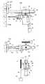
本発明のコンクリート構造物診断装置とそれを用いた診断方法について、図面を参照して詳細に説明する。図1は、本発明のコンクリート構造物診断装置の構成を示す模式図である。図2は、コンクリート構造物診断装置100の要部を示し、(a)側面図、(b)平面図、(c)は装置移動部の正面図である。 A concrete structure diagnostic apparatus and a diagnostic method using the same according to the present invention will be described in detail with reference to the drawings. FIG. 1 is a schematic diagram showing a configuration of a concrete structure diagnostic apparatus according to the present invention. FIG. 2 shows the main part of the concrete structure
図1、図2において、50は評価対象のコンクリート構造物を示す 1 and 2,
コンクリート構造物診断装置100は、装置固定部10と、装置移動部20と、装置移動部20に支持されたハンマードリル1と、装置移動部20に把持・固定されたレーザ変位計5と、レーザセンサー6と、加速度計7と、ハンマードリル1の電源線に取り付けられた電圧コード8aと、電流測定用のクランプセンサー8bに接続した電力計8と、データ収集装置9と、
評価対象コンクリート構造物の表面及び背面にマトリックス状に複数取り付けられた、ハンマードリルの打撃による弾性波の反射波及び透過波を検知する加速度計7x(図1には一部のみ図示)とから構成する。The concrete structure
Consists of an
前記装置固定部10は、評価対象のコンクリート構造物50の表面に固定するアンカー部3bと、該アンカー部3b背面に垂直に固定された所定長四角柱状のガイドレール3と、該ガイドレール3の一側(図1では下側)に嵌合されたラックギア3aとからなる。アンカー部3bは、コンクリート構造物50の表面に対して並行に取り付け、コンクリート構造物に固定するアンカーボルト51の嵌合孔が設けられている。 The
装置移動部20は、ガイド角穴21(図2(c)参照)を有し、ガイドレール3にガイド角穴21を挿嵌しガイドレール3の前後に摺動可能に形成されている。 The
装置移動部20はハンマードリル1を支持し、前記ガイド角穴21の中央に前記ラックギア3aに噛み合うピニオンギア4aを備え、ピニオンギア4aと同軸の滑車輪4に巻きつけた錘用ワイヤー4bに取り付けた重錘15により一定荷重でハンマードリル1のビット刃1cをコンクリート構造物50に押し当て、一定反力条件でハンマードリル1に自動削孔させる。 The
また装置移動部20がコンクリート構造物に対面する前方には、削孔深さの測定に用いるレーザ変位計5が取り付けられ、レーザ光5aをコンクリート構造物50に照射し、その反射光を受光して正確な距離を測定する。 Further, a
また、ハンマードリル1のチャック1bの表面に貼り付けたレーザセンサー専用の反射テープ6bにより、ハンマードリル1の回転数を測定するレーザセンサー6が装置移動部20に固定される。なお、この実施の形態では、レーザを用いた測定距離用の変位計、回転数測定用のセンサーを用いたが、別の方式による測定器を用いて行ってもよい。 Further, the
また、装置移動部20に支持されたハンマードリル1には反発硬度/原形波を測定する加速度計7を取り付ける。 The
ハンマードリル1の電源コード1aには、並列に電圧コード8aを接続し電力計8に引き込み電圧を測定する。また、電源コード1aにクランプセンサー8bを取付けクランププローブの出力を電力計8に接続して電流を測定する。 A
これらの各種測定器の情報は、データ収集装置9にリアルタイムで記録する。これらの接続はレーザ変位計用のアンプ5b、レーザセンサー6用のアンプ6c、加速度計7用のアンプ7bを介してマルチチャンネルの高速A/D変換を行う高速アナログ計測ユニット9aに接続され、さらに高速アナログ計測ユニット9aからパソコンインターフェースユニット9bを介してデータ収集用のパソコン9cに入力される。 Information on these various measuring instruments is recorded in the
図2(a)に示すように、ハンマードリル1は、装置固定部10のガイドレール3に摺動自在に挿入された装置移動部20に前後が吊下げ保持された状態で支持されている。 As shown in FIG. 2A, the
装置移動部20は、ガイドレール3のラックギア3aに噛み合うピニオンギア4aと同軸の滑車輪4を有し、滑車輪4の外周に結ばれて捲かれ地上に向けて垂らされた錘用ワイヤー4bの先端に錘15を吊り下げる。 The
錘15の重力により、滑車輪4に一定の回転力が与えられ、ピニオンギア4aがラックギア3a上を一定の反力で進行する。 A constant rotational force is applied to the
ハンマードリル1のチャック1bに臨む位置にはハンマードリルの回転数を測定するためのレーザセンサー6が設けられる。一方チャック1bには、レーザセンサー6のレーザ光6a(図示省略)を反射する反射テープ6bを貼り付ける。 A
図2(b)に示すように、装置移動部20の側面には、レーザ変位計5が取り付けられ、コンクリート構造物50の表面50aに向けてレーザ光5aを発射して、距離を計測することにより、削孔深さを測定する。 As shown in FIG. 2B, a
ハンマードリル1の背面には、ハンマードリルの反発硬度/原形波を測定する加速度計7を取り付ける。 An
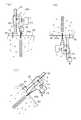
図3は、装置固定部20の実施の形態を示し、(a)は、アンカーボルト固定の形態、(b)は、吸着固定の形態を示す断面図である。 FIGS. 3A and 3B show an embodiment of the
図3(a)は、装置固定部20のアンカー部3bに嵌合孔が設けられて、アンカーボルト51をコンクリート構造物50に打ち込んで固定している。図3(b)は、アンカー部3bに、吸着空間3cを設け、真空ポンプ52により擬似真空とすることにより吸着固定する。後者は複数箇所の測定に際して取り付け、撤去作業をすばやく行うことができる。 In FIG. 3A, a fitting hole is provided in the
図4は、本発明のコンクリート構造物診断装置100の計測状態を示し、(a)は構造物の上面計測、(b)は構造物の下面計測、(c)は構造物の側面計測の状態を示す断面図である。 FIG. 4 shows a measurement state of the concrete structure
図4に示すように、本発明のコンクリート構造物診断装置100は、装置移動部20が、測定対象のコンクリート構造物50にハンマードリル1で削孔するビットの押し付け力(反力)を一定に保つ構成として錘15の重力を用いていることから、コンクリート構造物の、上面、下面、側面、斜面のあらゆる面の計測を行うことができる。 As shown in FIG. 4, in the concrete structure
なお、一定の反力とするため、ハンマードリル1及び取り付けられた計測センサーを含めた装置移動部20の重量を勘案した錘15を取り付け姿勢により交換する。 In addition, in order to set it as a fixed reaction force, the
図5は、本発明のコンクリート構造物診断装置100の、反射波形及び透過波形の計測状態を示す断面模式図である。 FIG. 5 is a schematic cross-sectional view showing the measurement state of the reflected waveform and transmitted waveform of the concrete structure
加速度計7xは、評価対象コンクリート構造物50の表面50a及び背面50bにマトリックス状に複数個取り付ける。尚図5では、加速度計7xの計測信号線、アナログ信号の出力用アンプ、パソコン接続のA/D変換器の図示は省略している A plurality of
ハンマードリル1の削孔位置の周囲の表面50aに一定距離間隔でマトリックス状に配置された加速度計7xは、ハンマードリル1の削孔打撃音源の弾性波がコンクリート構造物50の内部構造から反射する反射波を捉え、コンクリート構造物の背面50bにマトリックス状に配置された加速度計7xは、透過波を捉えて、内部構造の解析データを収集する。 The
コンクリート構造物内部に空洞、ジャンカ、打ち継ぎ部などの内部欠陥があれば、反射面の存在や弾性波の速度分布の違いによりその存在を特定することができる。このときドリル削孔位置を順次移動して各削孔位置に応じた弾性波を検出する。 If there are internal defects such as cavities, jumpers, joints, etc. inside the concrete structure, the presence can be specified by the presence of the reflecting surface and the difference in velocity distribution of elastic waves. At this time, the drill holes are sequentially moved to detect elastic waves corresponding to the respective positions.
図6は、反射波による境界面の評価例を示す図である。コンクリート構造物の内部に空洞、ジャンカ、打ち継ぎ部などの欠陥が存在する場合には、健全部と欠陥部の境界面が弾性波の反射面となり、コンクリート構造物の背面より浅い境界面からの弾性波の反射が検出される。 FIG. 6 is a diagram illustrating an example of evaluation of a boundary surface by a reflected wave. When there are defects such as cavities, jumpers, joints, etc. in the concrete structure, the boundary surface between the healthy part and the defective part becomes the reflection surface of the elastic wave, which is from the boundary surface shallower than the back of the concrete structure. Elastic wave reflection is detected.
反射波の解析では、ハンマードリル1に取り付けた加速度計7による音源の弾性波とドリル削孔面にアレイ配置した加速度計7xによる反射波の到達時間差を検討して境界面の推定図を作成する。 In the analysis of the reflected wave, an estimated drawing of the boundary surface is created by examining the arrival time difference between the elastic wave of the sound source by the
コンクリート構造物の背面からの反射波は、コンクリートの弾性波速度とコンクリート構造物の寸法から到達時間が推定されるが、内部欠陥に起因する境界面からの反射波は、背面からの反射波に比べて到達時間が短いことを利用して、識別される。本発明の測定においては、一定反力条件でのハンマードリル削孔時の打撃を音源とするため、入力弾性波の再現性が高く、解析精度を高くすることができる。 The reflected wave from the back of the concrete structure is estimated to arrive from the elastic wave velocity of the concrete and the size of the concrete structure, but the reflected wave from the interface due to internal defects is reflected in the reflected wave from the back. It is identified using the short arrival time. In the measurement of the present invention, the hammering drilling with a constant reaction force is used as a sound source, so the input elastic wave is highly reproducible and the analysis accuracy can be increased.
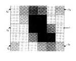
図7は、弾性波トモグラフィーによる低速度帯の評価例を示す図である。コンクリート構造物の内部に存在する空洞、ジャンカ、打ち継ぎ部などの欠陥部の弾性波速度は、健全部の弾性波速度に比べて低くなる。また、弾性波は、欠陥部を透過することで、減衰が大きくなる。弾性波トモグラフィーでは、このような弾性波速度の低速度帯/高減衰帯の識別を行う。 FIG. 7 is a diagram illustrating an evaluation example of a low speed band by elastic wave tomography. Elastic wave velocities of defective parts such as cavities, junkers, and joints existing inside the concrete structure are lower than those of sound parts. In addition, the acoustic wave is attenuated by passing through the defect portion. In the elastic wave tomography, the low velocity band / high attenuation band of the elastic wave velocity is identified.
弾性波トモグラフィーでは、ハンマードリル1に取り付けた加速度計7による音源の弾性波とドリル削孔面にアレイ配置した加速度計7xによる透過波の
到着時間差や減衰特性により低速度帯の評価や高減衰帯の評価を行ったものである。本発明の測定においては、一定反力条件でのハンマードリル削孔時の打撃を音源とするため、入力弾性波の再現性が高く、解析精度を高くすることができる。In the elastic wave tomography, the low velocity band is evaluated and the high attenuation band is determined by the arrival time difference and attenuation characteristics of the elastic wave of the sound source by the
次に、本発明のコンクリート構造物診断方法を説明する。図8は本発明のコンクリート構造物診断方法の流れ図である。 Next, the concrete structure diagnostic method of the present invention will be described. FIG. 8 is a flowchart of the concrete structure diagnosis method of the present invention.
まず、測定対象コンクリート構造物の表面に装置固定部をアンカーで固定する。(S1:装置固定工程) First, the device fixing part is fixed to the surface of the concrete structure to be measured with an anchor. (S1: Device fixing process)
次に、測定対象コンクリート構造物の表面及び背面にハンマードリルの打撃による弾性波の反射波及び透過波を検知する加速度計をマトリックス状に配設する。(S2:センサー設置工程) Next, accelerometers for detecting reflected waves and transmitted waves of elastic waves generated by hammer drills are arranged in a matrix on the front and back surfaces of the concrete structure to be measured. (S2: Sensor installation process)
次に、装置移動部の滑車輪に錘を取り付け、一定加重でハンマードリルのビット刃をコンクリート構造物の表面に押し付けながら削孔させる。(S3:削孔工程) Next, a weight is attached to the pulley wheel of the apparatus moving part, and a bit hole of a hammer drill is drilled while pressing it against the surface of the concrete structure with a constant load. (S3: Drilling process)
同時に、削孔中の削孔深さ、電流、電圧、総電力、反発硬度、弾性波の原波形及び、マトリックス状に配置された加速度計で検出される反射波形及び透過波形をリアルタイムで計測して記録する。(S4:計測記録工程) At the same time, the drilling depth, current, voltage, total power, rebound hardness, elastic wave original waveform, and reflected and transmitted waveforms detected by the accelerometers arranged in a matrix are measured in real time. Record. (S4: Measurement recording process)
計測された削孔深さと抵抗指標から劣化深さを評価する相関図表を作図する。(S5:劣化評価工程) A correlation chart for evaluating the deterioration depth from the measured drilling depth and the resistance index is drawn. (S5: Degradation evaluation process)
計測された弾性波の直達波、反射波の到達時間差による反射面の境界面評価図表を作図すると共に、透過波の到達時間差と減衰特性により弾性波トモグラフィーによるコンクリート構造物の内部評価図表を作成する。(S6:深部評価工程) Create a boundary evaluation chart of the reflecting surface based on the arrival time difference between the measured direct wave and reflected wave, and create an internal evaluation chart of the concrete structure by elastic wave tomography based on the arrival time difference and attenuation characteristics of the transmitted wave. . (S6: Deep part evaluation process)
なお、S1〜S4は、コンクリート構造物の計測箇所毎に行い、S5、S6についてはを複数箇所をまとめて実施することができる。 In addition, S1-S4 is performed for every measurement location of a concrete structure, and about S5 and S6, several locations can be implemented collectively.
1 ハンマードリル
1a 電源コード
1b チャック
1c ビット刃
3 ガイドレール
3a ラックギア
3b アンカー部
3c 吸着空間
4 滑車輪
4a ピニオンギア
4b 錘用ワイヤー
5 レーザ変位計
5a レーザ光
5b アンプ
6 レーザセンサー
6a レーザ光
6b 反射テープ
6c アンプ
7 加速度計
7b アンプ
7x 加速度計
8 電力計
8a 電圧コード
8b クランプセンサー
9 データ収集装置
9a 高速アナログ計測ユニット
9b パソコンインターフェースユニット
9c パソコン
10 装置固定部
15 錘
20 装置移動部
21 ガイド角穴
50 コンクリート構造物
50a 表面
50b 背面
51 アンカーボルト
52 真空ポンプ
100 コンクリート構造物診断装置DESCRIPTION OF
Claims (2)
Translated fromJapanese評価対象コンクリート構造物の表面及び背面にマトリックス状に複数取り付けられた、ハンマードリルの打撃による弾性波の反射波及び透過波を検知する加速度計と
前記の各種センサーに接続したAD変換器と、AD変換器とパソコンを接続するインターフェースユニットと、計測データを記録するパソコンとから構成し、
前記装置移動部は、前記ガイド角穴の中央に前記ラックギアに噛み合うピニオンギアを備え、ピニオンギアと同軸の滑車輪に巻かれた錘用ワイヤーに取り付けた錘により一定荷重でハンマードリルのビット刃が評価対象コンクリート構造物に押し当てられ、一定反力条件で自動削孔しながらハンマードリルの抵抗指標、反発硬度、弾性波の源波形、反射波形及び透過波形を計測することを特徴とするコンクリート構造物診断装置。An apparatus comprising an anchor portion fixed to the surface of a concrete structure to be evaluated, a guide rail having a rectangular columnar shape with a predetermined length fixed perpendicularly to the back surface of the anchor portion, and a rack gear fitted to one side of the guide rail A fixed portion, a device moving portion in which a guide square hole is inserted into a guide rail of the device fixing portion, and the guide rail can be slid back and forth, and supported by the device moving portion by vibration hitting and rotation of a bit blade A hammer drill for drilling holes in concrete structures, a displacement meter for measuring the drilling depth of the hammer drill held and fixed on the device moving part, a sensor for measuring the number of rotations of the hammer drill, and rebound hardness / original shape An accelerometer that measures waves, a voltage cord attached to the power line of the hammer drill, a wattmeter connected to a clamp sensor for current measurement,
An accelerometer that detects a reflected wave and a transmitted wave of an elastic wave by hitting with a hammer drill, and an AD converter connected to the various sensors described above, which are attached in a matrix on the surface and the back of the concrete structure to be evaluated Consists of an interface unit that connects the converter to a personal computer and a personal computer that records measurement data.
The device moving unit includes a pinion gear that meshes with the rack gear in the center of the guide square hole, and a bit blade of a hammer drill is fixed at a constant load by a weight attached to a weight wire wound around a pulley wheel coaxial with the pinion gear. A concrete structure that is pressed against a concrete structure to be evaluated and measures the resistance index, rebound hardness, elastic wave source waveform, reflection waveform and transmission waveform of a hammer drill while automatically drilling under a constant reaction force condition. Diagnostic equipment.
測定対象コンクリート構造物の表面に装置固定部をアンカーで固定する装置固定工程と、
測定対象コンクリート構造物の表面及び背面にハンマードリルの打撃による弾性波の反射波及び透過波を検知する加速度計をマトリックス状に配設するセンサー設置工程と、
装置移動部の滑車輪に錘を取り付け、一定加重でハンマードリルのビット刃をコンクリート構造物の表面に押し付けながら削孔させる削孔工程と、
削孔中の削孔深さ、電流、電圧、総電力、反発硬度、弾性波の原波形及び、マトリックス状に配置された加速度計で検出される反射波形及び透過波形をリアルタイムで計測して記録する計測記録工程と、
計測された削孔深さと抵抗指標から劣化深さを評価する相関図表を作図する劣化評価工程と、
計測された弾性波の直達波、反射波の到達時間差による反射面の境界面評価図表を作図すると共に、透過波の到達時間差と減衰特性により弾性波トモグラフィーによるコンクリート構造物の内部評価図表を作成する深部評価工程とからなることを特徴とするコンクリート構造物診断方法。A method for diagnosing a concrete structure using the concrete structure diagnostic apparatus according to claim 1,
A device fixing step of fixing the device fixing portion to the surface of the concrete structure to be measured with an anchor,
A sensor installation process in which accelerometers that detect reflected waves and transmitted waves of elastic waves generated by hammer drill strikes are arranged in a matrix on the surface and back of the concrete structure to be measured;
A drilling process in which a weight is attached to the pulley wheel of the device moving unit, and the bit drill blade is pressed against the surface of the concrete structure with a constant load,
Drilling depth, current, voltage, total power, rebound hardness, elastic wave original waveform, and reflected and transmitted waveforms detected by accelerometers arranged in matrix are recorded in real time. Measuring and recording process,
A deterioration evaluation process for drawing a correlation chart for evaluating the deterioration depth from the measured drilling depth and the resistance index,
Create a boundary evaluation chart of the reflecting surface based on the arrival time difference between the measured direct wave and reflected wave, and create an internal evaluation chart of the concrete structure by elastic wave tomography based on the arrival time difference and attenuation characteristics of the transmitted wave. A method for diagnosing a concrete structure comprising a deep evaluation step.
Priority Applications (1)
| Application Number | Priority Date | Filing Date | Title |
|---|---|---|---|
| JP2006017831AJP4214290B2 (en) | 2006-01-26 | 2006-01-26 | Concrete structure diagnostic apparatus and diagnostic method using the same |
Applications Claiming Priority (1)
| Application Number | Priority Date | Filing Date | Title |
|---|---|---|---|
| JP2006017831AJP4214290B2 (en) | 2006-01-26 | 2006-01-26 | Concrete structure diagnostic apparatus and diagnostic method using the same |
Publications (2)
| Publication Number | Publication Date |
|---|---|
| JP2007198907A JP2007198907A (en) | 2007-08-09 |
| JP4214290B2true JP4214290B2 (en) | 2009-01-28 |
Family
ID=38453654
Family Applications (1)
| Application Number | Title | Priority Date | Filing Date |
|---|---|---|---|
| JP2006017831AActiveJP4214290B2 (en) | 2006-01-26 | 2006-01-26 | Concrete structure diagnostic apparatus and diagnostic method using the same |
Country Status (1)
| Country | Link |
|---|---|
| JP (1) | JP4214290B2 (en) |
Families Citing this family (12)
| Publication number | Priority date | Publication date | Assignee | Title |
|---|---|---|---|---|
| JP5082168B2 (en)* | 2007-09-13 | 2012-11-28 | 東京都 | Measuring method and apparatus for heat receiving effect of fireproof building by ultrasonic wave |
| KR100950543B1 (en) | 2009-02-20 | 2010-03-30 | 박준 | Integrity-diagnostic apparatus of concrete electric pole |
| JP5271941B2 (en)* | 2010-03-15 | 2013-08-21 | 飛島建設株式会社 | Non-destructive detection system and non-destructive detection method |
| CN102109443B (en)* | 2010-12-24 | 2012-07-25 | 同济大学 | High-accuracy hydraulic repeated loading test device |
| US10352912B2 (en) | 2016-09-15 | 2019-07-16 | Kabushiki Kaisha Toshiba | Structure evaluation system, structure evaluation apparatus, and structure evaluation method |
| US10458954B2 (en) | 2016-09-15 | 2019-10-29 | Kabushiki Kaisha Toshiba | Structure evaluation system, structure evaluation apparatus, and structure evaluation method |
| WO2018051534A1 (en)* | 2016-09-15 | 2018-03-22 | 株式会社東芝 | Structure evaluation system, structure evaluation device, and structure evaluation method |
| KR101721975B1 (en)* | 2016-10-17 | 2017-03-31 | 주식회사 다우컨설턴트 | Carbonation Depth Measurement Device for Safety Diagnosis of Reinforced Concrete Structure |
| KR102057733B1 (en)* | 2019-08-21 | 2019-12-19 | 주식회사 서림정밀안전진단 | Carbonation measuring device of concrete structure |
| CN112179989B (en)* | 2020-10-23 | 2022-05-27 | 河北建筑工程学院 | A monitoring device for monitoring the dynamic situation of concrete rupture |
| CN113588468A (en)* | 2021-04-12 | 2021-11-02 | 仪征市四方建设工程检测有限公司 | Concrete resilience detection device |
| CN115290865B (en)* | 2022-10-10 | 2022-12-23 | 中国建筑第二工程局有限公司 | Assembled building grouting compaction detection device and detection method thereof |
- 2006
- 2006-01-26JPJP2006017831Apatent/JP4214290B2/enactiveActive
Also Published As
| Publication number | Publication date |
|---|---|
| JP2007198907A (en) | 2007-08-09 |
Similar Documents
| Publication | Publication Date | Title |
|---|---|---|
| JP4214290B2 (en) | Concrete structure diagnostic apparatus and diagnostic method using the same | |
| US7631560B2 (en) | Methods of inspecting rotary drill bits | |
| JP4667228B2 (en) | Pile inspection method and sensor crimping device | |
| CN101650341B (en) | Method for detecting anchoring quality of anchor rope and anchor rod based on reflection device embedded at bottom of hole in advance | |
| JP7029303B2 (en) | Non-destructive diagnostic method for PC grout filling state | |
| JP2010271116A (en) | Sound hammer for soundness diagnosis and method for soundness diagnosis of concrete structure using the hammer | |
| JP3770668B2 (en) | Method for detecting internal defects in structures | |
| CN109100421B (en) | Device and method for detecting grouting compactness of anchor cable in embedded mode | |
| JP2001004604A (en) | Inspecting method for flaw in concrete structure | |
| JP2014211333A (en) | Detached survey method and device inside concrete | |
| JP3198840U (en) | Prop road boundary inspection system | |
| JP2002115491A (en) | Diagnosis method for lining concrete and its diagnosis device | |
| JP2009041978A (en) | Soundness diagnosis method by sound analysis | |
| KR20040052961A (en) | The non-destruction test method for the spot of pipe, and the program of the read to record vehicle by the computer | |
| JP5897199B1 (en) | Anchor bolt soundness evaluation judgment method | |
| JP7209803B2 (en) | Non-destructive diagnosis method of PC grout filling state | |
| CN111174960A (en) | Residual stress detection system and method | |
| JP6128432B2 (en) | Anchor soundness inspection device and anchor soundness inspection method | |
| JP2003014709A (en) | Defect probing method for concrete due to strike based on attenuation of energy | |
| CN116297879A (en) | A quantitative calibration system and method for the sensitivity coefficient of an acoustic emission sensor | |
| JP4413089B2 (en) | Inspection method for buried pipes | |
| JP4413082B2 (en) | Inspection method for buried pipes | |
| JP2007121123A (en) | Nondestructive inspection method and inspection apparatus for the degree of corrosion of reinforcing bars in concrete structures by ultrasonic method | |
| JP2006008385A (en) | Escalator handrail deterioration diagnosis method | |
| JP2007033139A (en) | Soundness diagnosis system and soundness diagnosis method |
Legal Events
| Date | Code | Title | Description |
|---|---|---|---|
| A977 | Report on retrieval | Free format text:JAPANESE INTERMEDIATE CODE: A971007 Effective date:20080922 | |
| TRDD | Decision of grant or rejection written | ||
| A01 | Written decision to grant a patent or to grant a registration (utility model) | Free format text:JAPANESE INTERMEDIATE CODE: A01 Effective date:20080930 | |
| A01 | Written decision to grant a patent or to grant a registration (utility model) | Free format text:JAPANESE INTERMEDIATE CODE: A01 | |
| A61 | First payment of annual fees (during grant procedure) | Free format text:JAPANESE INTERMEDIATE CODE: A61 Effective date:20081017 | |
| R150 | Certificate of patent or registration of utility model | Ref document number:4214290 Country of ref document:JP Free format text:JAPANESE INTERMEDIATE CODE: R150 Free format text:JAPANESE INTERMEDIATE CODE: R150 | |
| FPAY | Renewal fee payment (event date is renewal date of database) | Free format text:PAYMENT UNTIL: 20111114 Year of fee payment:3 | |
| FPAY | Renewal fee payment (event date is renewal date of database) | Free format text:PAYMENT UNTIL: 20121114 Year of fee payment:4 | |
| FPAY | Renewal fee payment (event date is renewal date of database) | Free format text:PAYMENT UNTIL: 20131114 Year of fee payment:5 | |
| FPAY | Renewal fee payment (event date is renewal date of database) | Free format text:PAYMENT UNTIL: 20131114 Year of fee payment:5 | |
| FPAY | Renewal fee payment (event date is renewal date of database) | Free format text:PAYMENT UNTIL: 20141114 Year of fee payment:6 | |
| S531 | Written request for registration of change of domicile | Free format text:JAPANESE INTERMEDIATE CODE: R313531 | |
| R350 | Written notification of registration of transfer | Free format text:JAPANESE INTERMEDIATE CODE: R350 | |
| S531 | Written request for registration of change of domicile | Free format text:JAPANESE INTERMEDIATE CODE: R313531 | |
| R350 | Written notification of registration of transfer | Free format text:JAPANESE INTERMEDIATE CODE: R350 |