JP4213840B2 - Portable image reproducing apparatus and operation control method thereof, and portable imaging apparatus and operation control method thereof - Google Patents
Portable image reproducing apparatus and operation control method thereof, and portable imaging apparatus and operation control method thereofDownload PDFInfo
- Publication number
- JP4213840B2 JP4213840B2JP2000064252AJP2000064252AJP4213840B2JP 4213840 B2JP4213840 B2JP 4213840B2JP 2000064252 AJP2000064252 AJP 2000064252AJP 2000064252 AJP2000064252 AJP 2000064252AJP 4213840 B2JP4213840 B2JP 4213840B2
- Authority
- JP
- Japan
- Prior art keywords
- image
- file
- audio
- data
- read
- Prior art date
- Legal status (The legal status is an assumption and is not a legal conclusion. Google has not performed a legal analysis and makes no representation as to the accuracy of the status listed.)
- Expired - Fee Related
Links
Images


Classifications
- H—ELECTRICITY
- H04—ELECTRIC COMMUNICATION TECHNIQUE
- H04N—PICTORIAL COMMUNICATION, e.g. TELEVISION
- H04N5/00—Details of television systems
- H04N5/76—Television signal recording
- H04N5/765—Interface circuits between an apparatus for recording and another apparatus
- H04N5/77—Interface circuits between an apparatus for recording and another apparatus between a recording apparatus and a television camera
- H04N5/772—Interface circuits between an apparatus for recording and another apparatus between a recording apparatus and a television camera the recording apparatus and the television camera being placed in the same enclosure
- H—ELECTRICITY
- H04—ELECTRIC COMMUNICATION TECHNIQUE
- H04N—PICTORIAL COMMUNICATION, e.g. TELEVISION
- H04N5/00—Details of television systems
- H04N5/76—Television signal recording
- H04N5/907—Television signal recording using static stores, e.g. storage tubes or semiconductor memories
- H—ELECTRICITY
- H04—ELECTRIC COMMUNICATION TECHNIQUE
- H04N—PICTORIAL COMMUNICATION, e.g. TELEVISION
- H04N9/00—Details of colour television systems
- H04N9/79—Processing of colour television signals in connection with recording
- H04N9/7921—Processing of colour television signals in connection with recording for more than one processing mode
Landscapes
- Engineering & Computer Science (AREA)
- Multimedia (AREA)
- Signal Processing (AREA)
- Television Signal Processing For Recording (AREA)
- Studio Devices (AREA)
Description
Translated fromJapanese【0001】
【技術分野】
この発明は,記録媒体に記録されている画像データを再生する携帯型画像再生装置およびその動作制御方法ならびに記録媒体に画像データを記録する携帯型撮像装置に関する。
【0002】
【発明の背景】
ムービ・ビデオ・カメラなどは,被写体の動画記録と音声記録とが同時にできる。しかしながら,動画の記録と音声の記録とを別個独立に行うことは考えられていない。このために,動画の記録と音声の記録とを別々に行うときであっても動画の記録系の回路と音声の記録系の回路とが一体となって動作することとなってしまう。このようなことは,再生においても同じである。
【0003】
【発明の開示】
この発明は,動画などの画像の再生と音声の再生とを別々に独立して行うことを目的とする。
【0004】
また,この発明は,画像と音声とを互いに関連づけて記録することができるようにすることを目的とする。
【0005】
この発明による携帯画像再生装置は,画像を表す画像データおよび音声を表す音声データのいずれのデータも記録可能な記録媒体に記録されているデータを読み取るデータ読み取り手段,上記データ読み取り手段により読み取られた画像データを画像再生処理する画像再生処理手段,上記画像再生処理手段により画像再生処理された画像データによって表された画像を表示するように表示装置を制御する第1の表示制御手段,上記データ読み取り手段により読み取られた音声データを音声再生処理する音声再生処理手段,ならびに上記音声再生処理手段により音声再生処理された音声データによって表された音声を,上記表示装置における画像表示とは独立に(画像表示と音声出力とを互いに関連せずに行なう,画像表示または音声出力の一方を行なう,互いに関連した画像表示と音声出力とを同時に行なうことのいずれも含む)出力する音声出力手段を備えていることを特徴とする。
【0006】
この発明は,上記装置に適した動作制御方法も提供している。すなわち,この方法は,画像を表す画像データおよび音声を表す音声データのいずれのデータも記録可能な記録媒体に記録されているデータを読み取り,読み取られた画像データを画像再生処理し,画像再生処理された画像データによって表された画像を表示装置に表示し,読み取られた音声データを音声再生処理し,音声再生処理された音声データによって表された音声を,上記表示装置における画像表示とは独立に出力するものである。
【0007】
この発明によると,画像データおよび音声データのいずれも記録可能な記録媒体に記録されているデータが読み取られる。読み取られたデータが画像データであれば画像再生処理が行われ,読み取られた画像データによって表される画像が表示装置に表示される。また,読み取られたデータが音声データであれば音声再生処理が行なわれ,読み取られた音声データによって表される音声が出力される。
【0008】
画像と音声とが全く無関係であったとしても,画像の表示と音声の出力とを同時に行うことができる。もっとも,互いに関連のある画像と音声とを同時に表示および音声出力することもできる。画像表示のみまたは音声出力のみとすることもできるのはいうまでもない。
【0009】
読み取られたデータが画像データか音声データかを判定し,上記記録媒体から読み取られたデータが画像データと判定されたことに応じて,読み取られた画像データを画像再生処理し,上記記録媒体から読み取られたデータが音声データと判定されたことに応じて,読み取られた音声データを音声再生処理するようにしてもよい。
【0010】
読み取られたデータが画像データか音声データかに応じて,画像表示または音声出力を指定することなく,画像表示または音声出力することができるようになる。
【0011】
画像再生モードまたは音声再生モードをいずれか選択的に設定するモード設定手段をさらに備えてもよい。この場合には,設定されたモードに応じて,読み取られたデータが画像データか音声データかを判定することとなろう。
【0012】
上記画像データには画像データであることを識別するための画像識別データが関連づけられており,かつ上記音声データには音声データであることを識別するための音声識別データが関連づけられている場合には,上記画像識別データまたは上記音声識別データにもとづいて,読み取られたデータが画像データか音声データかを判定するようにしてもよい。
【0013】
上記記録媒体にはヘッダ記録領域とデータ記録領域とが含まれており,上記データ記録領域に上記画像データおよび上記音声データが記録されており,かつ上記ヘッダ記録領域に上記データ記録領域の所定の領域に記録されているデータが画像データであるか音声データであるかを示す識別データが記録されているときには,上記ヘッダ記録領域に記録されている識別データにもとづいて,読み取られたデータが画像データか音声データかを判定することができる。
【0014】
被写体を撮像し,被写体像を表す画像データを出力する撮像手段,および上記撮像手段から出力された画像データを上記記録媒体に記録する記録制御手段をさらに備えてもよい。
【0015】
画像再生モード指令または音声再生モード指令を選択的に与えるモード指令スイッチ,および上記モード指令スイッチから上記画像再生モード指令または上記音声モード指令が与えられたことに応答して,電源をオンとする電源制御手段をさらに備えてもよい。
【0016】
上記モード指令スイッチからのモード指令に応じて画像再生モードまたは音声再生モードが設定できる。また,モードを選択するだけで,電源がオンとなるので,電源スイッチをオンとする手間を省くことができる。
【0017】
電源スイッチ,上記電源スイッチがオンとされたことに応答して,電源をオンする電源制御手段,画像再生モード指令または音声再生モード指令を選択的に与えるモード指令スイッチ,ならびに上記モード指令スイッチにより画像再生モード指令が与えられたことに応じて,上記画像再生処理手段および上記表示制御手段への電源の供給を開始し,かつ上記モード指令スイッチにより音声再生モード指令が与えられることに応じて,上記音声再生処理手段および上記音声出力手段への電源の供給を開始する電源供給制御手段をさらに備えてもよい。
【0018】
画像再生モードまたは音声再生モードをいずれか選択的に設定可能とし,読み取られたデータのうち,上記モード設定手段によって設定されたモードに対応するデータが格納されているファイルの名称を表示してもよい。
【0019】
現在設定されているモードで表示可能な画像または出力可能な音声が分かる。
【0020】
読み取られた画像データと音声データとが互いに関連づけられているかどうかを判定し,上記画像データと上記音声データとが互いに関連づけられていると判定されたことに応じて,読み取られた画像データによって表される画像の表示中に読み取られた音声データによって表される音声を出力するように上記画像表示制御手段および上記音声出力手段を制御してもよい。
【0021】
画像の表示中に互いに関連している音声を出力することができるようになる。
【0022】
上記データ読み取り手段により読み取られたデータのうち互いに関連づけられている画像データと音声データとを検出するデータ検出手段,および上記データ検出手段により検出されたデータが格納されているファイルの名称を他のファイルの名称と区別して表示するように表示装置を制御することが好ましい。
【0023】
どのファイルに関連しているファイルがあるかどうかが一見して分かる。
【0024】
読み取られた画像データによって表される画像を上記表示装置に表示し,一覧表示された画像を表す画像データのうち,他の画像データによって表される画像データまたは音声データと関連づけられている画像データによって表される画像を他の画像と区別して表示することが好ましい。
【0025】
表示されている画像に関連づけられた画像データまたは音声データがあることを一見してわかるようになる。
【0026】
上記関連づけられている画像データによって表される画像が選択されたことに応じて,その関連づけられている他の画像データまたは音声データによって表される画像の表示または音声の出力が行われるように上記表示制御手段または上記音声出力手段を制御することが好ましい。
【0027】
この発明による携帯型撮像装置は,被写体を撮像し,被写体像を表す画像データを出力する撮像手段,音声データを入力する音声データ入力手段,上記撮像手段から出力された画像データと上記音声データ入力手段から入力した音声データとのうち互いに関連づけるべき画像データと音声データとを選択する選択手段,および上記選択手段により選択された画像データと音声データとを互いに関連づけて記録媒体に記録する記録制御手段を備えていることを特徴とする。
【0028】
この発明は,上記装置に適した動作制御方法も提供している。すなわち,この方法は,被写体を撮像し,被写体像を表す画像データを得,音声データを入力し,撮像により得られた画像データと入力した音声データとのうち互いに関連づけるべき画像データと音声データとを選択し,選択された画像データと音声データとを互いに関連づけて記録媒体に記録するものである。
【0029】
この発明によると,関連づけるべき画像データと音声データとを選択することができ,選択された画像データと音声データとが互いに関連づけられて記録媒体に記録される。所望の画像データと音声データとを任意の組み合わせで記録媒体に互いに関連づけて記録することができるようになる。
【0030】
【実施例の説明】
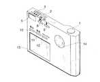
図1は,この発明の実施例を示すもので,ディジタル・カメラを前面から見た斜視図である。このディジタル・カメラは,静止画撮影機能,動画撮影機能,音声記録機能,静止画再生機能,動画再生機能および音声再生機能を有している。
【0031】
ディジタル・カメラの上面において前面から見て左側には,シャッタ・レリーズ・ボタン1が設けられている。また,右側には記録モードまたは再生モードを設定するための記録/再生モード・スイッチ2および電源のオフ,静止画撮影もしくは再生,動画再生もしくは記録または音声記録もしくは再生を設定するためのモード・スイッチ3が設けられている。
【0032】
ディジタル・カメラの前面においてほぼ中央には,撮像レンズ6が設けられている。また,前面の右上には,光学的ビューファインダ5が設けられている。この光学的ビュー・ファインダ5の左側にはストロボ4が設けられている。
【0033】
ディジタル・カメラの右側面には,メモリ・カードの挿入口7が形成されている。
【0034】
図2は,ディジタル・カメラを背面から見た斜視図である。
【0035】
ディジタル・カメラの左下には液晶表示画面13が設けられている。この液晶表示画面13の上には,液晶表示画面13をオン,オフ制御するための表示スイッチ10,決定指令を与えるための決定スイッチ11およびキャンセル・スイッチ12が設けられている。また,液晶表示画面13の右上には上下左右の各矢印が形成されている上下左右ボタン14が設けられている。上下左右ボタン14に形成されている各矢印は押下できる。
【0036】
ディジタル・カメラの背面の上部には,マクロ・モードの設定スイッチ8およびストロボ発光指令を与えるための発光スイッチ9が設けられている。
【0037】
図3は,ディジタル・カメラの電気的構成を示すブロック図である。
【0038】
ディジタル・カメラの全体の動作は,システム制御回路29によって統括される。
【0039】
上述した各スイッチ類(シャッタ・レリーズ・ボタン1,モード・スイッチ2,3,スイッチ8,9,10,11,12および上下左右ボタン14)50から与えられる各種指令信号は,MPU(micro processing unit )52を介してシステム制御回路29に入力する。
【0040】
バッテリィ57から与えられる電圧は,電圧制御回路54によって制御されるDC/DCレギュレータ55から各回路に与えられる。また,インバータ56によって,液晶表示装置用のバックライト58のオンおよびオフならびに輝度レベルがそれぞれ調整される。電圧制御回路54およびインバータ56は,MPU52によって制御される。
【0041】
TG(タイミング・ジェネレータ)およびCCDドライバ31が含まれており,このTGおよびCCDドライバ31から各種制御パルスが出力され,CCD21ならびにCDS(相関二重サンプリング回路)およびA/D変換回路22に入力する。
【0042】
撮像レンズ6によって被写体像がCCD21の受光面上に結像する。CCD21から被写体像を表す映像信号が出力され,CDSおよびA/D変換回路22に入力する。このCDSおよびA/D変換回路において相関二重サンプリングおよびアナログ/ディジタル変換処理が行われ,ディジタル画像データが出力される。ディジタル画像データは,DSP(ディジタル信号処理回路)33内の画像処理およびCCD駆動回路23に与えられ色バランス調整,ガンマ補正などの所定の画像処理が行われる。
【0043】
ディジタル画像データは,画像D/A変換回路24に与えられ,アナログ映像信号に戻される。アナログ映像信号は,液晶表示装置ドライバ25を介して液晶表示装置13に与えられることにより撮影した被写体像が動画で表示される。
【0044】
この実施例によるディジタル・カメラは,映像信号を出力することもできる。このために映像信号増幅回路26が含まれている。画像D/A変換回路24から出力されたアナログ映像信号は,映像信号増幅回路26を介して出力されることとなる。
【0045】
シャッタ・レリーズ・ボタン1が押されると(動画記録モードではシャッタ・レリーズ・ボタン1が押されている間),上述のようにして画像処理およびCCD駆動回路23から出力された画像データは,DRAMおよび圧縮/伸長回路29に与えられ,一時的に記憶される。また,このDRAMおよび圧縮/伸長回路29においてデータ圧縮が行われる。
【0046】
データ圧縮された画像データは,カードおよびメモリ制御回路30の制御のもとにメモリ・カード59に与えられ,記録される。
【0047】
また,メモリ・カード59に記録されている画像データは,カードおよびメモリ制御回路30により読み取られ,DRAMおよび圧縮/伸長回路27に入力する。DRAMおよび圧縮/伸長回路27においてデータ伸長が行われ,画像D/A変換回路24においてアナログ映像信号に変換される。液晶表示装置ドライバ25を介して液晶表示装置13に与えられることにより,メモリ・カード59に記録されている画像データによって表される画像が液晶表示装置13に表示されることとなる。
【0048】
マイクロフォン41に入力した音声は,音声信号に変換されドライバ増幅回路42において増幅される。増幅された音声信号は,A/DおよびD/A変換回路43においてディジタル音声データに変換される。ディジタル音声データは,音声処理回路44を介してDRAMおよび圧縮/伸長回路27に入力する。DRAMおよび圧縮/伸長回路27において,音声圧縮が行われる。音声圧縮された音声データは,カードおよびメモリ制御回路30の制御のもとにメモリ・カード59に与えられ,記録される。
【0049】
また,メモリ・カード59に記録されている音声データはカードおよびメモリ制御回路30により読み取られ,DRAMおよび圧縮/伸長回路27において音声伸長が行われる。伸長された音声データは,音声処理回路44を介してA/DおよびD/A変換回路によりアナログ音声信号に変換される。変換された音声信号は,ドライバおよび増幅回路42により増幅されてスピーカ45に与えられて音声として出力される。
【0050】
また,ディジタル・カメラには,ヘッドフォンを接続することもできる。音声処理回路44から出力された音声信号は,ヘッドフォン・ドライバ46を介して,ヘッドフォンから音声として出力される。
【0051】
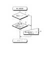
図4は,メモリ・カード59のデータ構造を示している。
【0052】
メモリ・カード59には,ヘッダ記録領域とデータ記録領域とが含まれている。
【0053】
データ記録領域には,上述したように静止画ファイル(データ),動画ファイルおよび音声ファイルが記録される。データ記録領域には複数の記録エリアが含まれている(もちろん,この記録エリアは物理的に存在しなくともよいのはいうまでもない)。記録エリア1,2,3,4,6には静止画ファイルが格納されている。記録エリア5には動画ファイルが格納されている。記録エリア7および8には音声ファイルが格納されている。
【0054】
それぞれの記録エリアには,格納されているファイルが静止画ファイルか,動画ファイルか,音声ファイルかを識別するための識別符号データも記録されている。静止画ファイルが格納されている記録エリアには,静止画であることを示す識別符号「S」を示すデータが記録されている。動画ファイルが格納されている記録エリアには,動画であることを示す識別符号「M」を示すデータが記録されている。音声ファイルが格納されている記録エリアには,音声であることを示す識別符号「A」を示すデータが格納されている。これらの識別データは,モード・スイッチ3により設定されたモードにもとづいてデータ記録領域に対応するエリアに記録されるのはいうまでもない。
【0055】
ヘッダ記録領域には,メモリ・カード59の管理データが記録されている。さらにこの実施例においては,ヘッダ記録領域には,管理データのほかにデータ記録領域に記録されているファイルのうち関連するファイルがどの記録エリアに記録されているかを示す関連データも記録されている。たとえば,記録エリア1に記録されているファイルに関連するファイルは,記録エリア2および6にそれぞれ記録されているファイルである。
【0056】
図5は,静止画記録モードの設定処理手順を示すフローチャートである。
【0057】
上述したようにモード・スイッチ2と3との組み合わせにより静止画記録もしくは再生,動画記録もしくは再生,音声記録もしくは再生または電源オフを設定することができる。
【0058】
静止画記録モードを設定するときには,まず,電源がオンとされているかどうかがチェックされる(ステップ71)。モード・スイッチ3が静止画モード,動画モードまたは音声モードのいずれかに設定されていると電源はオンとなっている。電源がオンとなっているとモード・スイッチ2が記録モードに設定され,かつモード・スイッチ2が静止画モードとなっているかどうかがチェックされる(ステップ72)。
【0059】
電源オンとなっていないか(ステップ71でNO),または電源がオンとなっていても静止画記録モードとなっていなければ(ステップ72でNO),モード・スイッチ2および3がユーザによって操作され,モード・スイッチ2は記録モードに,モード・スイッチ3は静止画記録モードにそれぞれ設定される。これによりシャッタ・レリーズ・ボタン1の押下に応じて撮像された被写体像を表す画像データがメモリ・カード59に記録されることとなる。
【0060】
もちろん,モード・スイッチ3が1つのスイッチにより静止画記録モード,静止画再生モード,動画記録モード,動画再生モード,音声記録モード,音声再生モードの設定が可能なように構成してもよいのはいうまでもない。記録/再生モード・スイッチ2が不要となる。
【0061】
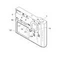
図6は,ディジタル・カメラを背面から見た斜視図である。この図において,図2に示すものと同一物には同一符号を付して説明を省略する。
【0062】
ディジタル・カメラの上面において左側には電源スイッチ3Aが設けられている。この電源スイッチ3Aによりディジタル・スチル・カメラの電源がオンまたはオフされる。
【0063】
ディジタル・カメラの背面の上下左右ボタン14の回りには回転自在なモード・ダイアル15が設けられている。モード・ダイアル15には,モードを示すための矢印15Aが形成されている。モード・ダイアル15の回りには「静止画」,「動画」および「音楽」の文字が記載されている。モード・ダイアル15の矢印が指した文字のモードに設定されることとなる。
【0064】
図7は,図6に示すディジタル・カメラにおいて静止画記録モードを設定するときの処理手順を示すフローチャートである。
【0065】
電源スイッチ3Aにより電源がオンされているかどうかがチェックされる(ステップ81)。電源がオンされていなければ(ステップ81でNO),ユーザによって電源スイッチ3Aが操作され,電源がオンとされる(ステップ82)。
【0066】
つづいて,モード設定スイッチ2が記録モードとされ,かつモード設定ダイアル15が静止画モードとされているかどうかがチェックされる(ステップ83)。記録/再生モード・スイッチ2が記録モードとされ,かつモード設定ダイアル14が静止画モードとされていると静止画記録モードに設定されていることとなる(ステップ83でYES)。そうでなければ(ステップ83でNO),ユーザにより記録/再生モード・スイッチ2が記録モードとされ,かつモード設定ダイアル14が静止画モードとされ,静止画記録モードに設定される(ステップ84)。
【0067】
このようにして,静止画記録モードに設定されると,シャッタ・レリーズ・ボタン1の押下に応答して被写体が撮像され,被写体像を表す画像データがメモリ・カード59に記録される。
【0068】
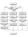
図8は,ディジタル・カメラにおける再生処理の手順を示すフローチャートである。
【0069】
上述したように記録/再生モード・スイッチ2により再生モードが設定されると,モード・スイッチ3のモードが静止画モード(静止画再生モード),動画モード(動画再生モード),音楽モード(音楽再生モード)のどのモードに設定されるかがチェックされる(ステップ91)。
【0070】
静止画再生モードに設定されると,静止画の再生に必要な回路にDC/DCレギュレータ55から電圧が供給される。静止画の再生に不要な回路である音楽再生用の回路はオフとされ,電圧の供給が停止させられる(ステップ92)。具体的には,ヘッドフォン・ドライバ46,ドライバおよび増幅回路43ならびにA/DおよびD/A変換回路43への電圧供給が停止する。
【0071】
ディジタル・カメラに装填されているメモリ・カード59に記録されているファイルのうち,ファイル識別符号を参照して静止画ファイルが読み出され,再生される(ステップ94)。すなわち,識別符号が「S」となっている記録エリアに記録されているファイルがメモリ・カード59から読み出され,再生される。システム制御回路29において,再生された静止画ファイルから縮小画像を表す画像データが生成される。もっとも静止画ファイルに縮小画像データが付随していれば,縮小画像データ変換処理が不要なのはいうまでもない。
【0072】
生成された縮小画像データが液晶表示装置13に与えられることにより,図9に示すような静止画の縮小画像が一覧表示される(ステップ94)。一覧表示されている縮小画像中において一の縮小画像のみが輝度が明るくされ,他の縮小画像と区別されている(図9においてはハッチングで示す)。ハッチングで示されている画像がユーザによって選択されている画像となる。上下左右ボタン14に形成されている上矢印,下矢印,左矢印または右矢印が押されることにより,上,下,左または右の画像が明るくなり,他の画像を選択することができる。
【0073】
実行ボタン10が押されると,輝度が明るくされた画像が選択されたと見なされ(ステップ95でYES),選択されている縮小画像に対応する静止画ファイルがメモリ・カード59から読み出され,再生される。再生された静止画画像データが液晶表示装置13に与えられることにより,液晶表示装置13の表示画面全体にわたって静止画が表示されることとなる(ステップ96)。
【0074】
動画再生モードが選択されると(ステップ91),静止画再生モードと同様に,音楽再生用の回路がオフされる(ステップ101 )。また,動画ファイルがメモリ・カード59から読み出され動画ファイルを示す画像が液晶表示装置13の表示画面上に一覧表示される(ステップ102 )。静止画の選択と同様にして動画ファイルが選択されると(ステップ103 でYES),選択された動画ファイルによって表される動画が液晶表示装置13の表示画面全体にわたって表示されることとなる(ステップ104 )。
【0075】
音楽再生モードが選択されると(ステップ91),画像再生用の回路がオフとされる。具体的には,液晶表示装置ドライバ25,液晶表示装置13,液晶表示装置用バックライト58,インバータ56および信号増幅回路26がそれぞれオフとされる。また,画像の記録系の回路であるCDSおよびA/D変換回路22ならびにTGおよびCCDドライバ31もオフとしてもよい。
【0076】
メモリ・カード59から識別符号を参照して音楽ファイルが読み出される。読み出された音楽ファイルを示す画像が液晶表示装置13の表示画面に一覧表示される(ステップ112 )。静止画および動画の選択と同様に音楽ファイルがユーザによって選択される(ステップ113 )。選択された音楽ファイルがメモリ・カード59から読み出される。スピーカ45またはヘッドフォンから音楽が出力されることとなる(ステップ114 )。
【0077】
上述した再生処理においては,静止画再生,動画再生および音楽再生のうち,ユーザが所望の再生モードを選択し,対応するファイルをメモリ・カードから読み出しているが,再生モードを選択することなく先にファイルを選択し,選択されたファイルに対応するモードで再生させることもできる。このような再生処理について次の説明する。
【0078】
図10は,ディジタル・カメラを背面から見た斜視図である。この図において図2に示すものと同一物には同一符号を付して説明を省略する。
【0079】
上下左右ボタン14の回りには回転自在なモード・ダイアル16が設けられている。モード・ダイアル16には,矢印16Aが形成されている。モード・ダイアル16の回りには,「静止画記録」,「動画記録」,「音楽記録」,「再生」および「オフ」の各文字が記載されている。
【0080】
「静止画記録」,「動画記録」,「音楽記録」,「再生」および「オフ」の文字のうち,モード・ダイアル16に形成されている矢印16Aが指した文字のモードが設定される。
【0081】
図11は,モード・ダイアル16の矢印16Aにより「再生」が指定されたときのディジタル・カメラの処理手順を示すフローチャートである。
【0082】
再生モードに設定されているかどうかがチェックされる(ステップ121 )。再生モードに設定されていなければ(ステップ121 でNO),ユーザによってモード・ダイアル16が回され再生モードとされる(ステップ122 )。
【0083】
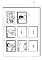
再生モードとなると,メモリ・カード59に記録されているすべてのファイルを表す画像が液晶表示装置13の表示画面上に一覧表示される(図12参照)。静止画ファイルについては,上述したように必要に応じて縮小処理が行われるのはいうまでもない。
【0084】
上述したのと同様に上下左右ボタン14を用いて,液晶表示装置13の表示画面上に表示された画像の中からユーザによって所望の画像が選択される(ステップ123 )。選択された画像に対応するファイル(静止画ファイル,動画ファイルまたは音楽ファイル)がメモリ・カード59から読み出される。読み出されたファイルの識別符号を表わすデータがチェックされる(ステップ124 )。
【0085】
識別データをチェックした結果,選択された画像が静止画であることが分かると(ステップ125 でYES),上述した静止画再生モードとなる(ステップ126 )。これにより,音楽再生用の回路はオフされる。読み出された静止画ファイルが再生され(ステップ127 ),液晶表示装置13の表示画面上全体にわたって,選択された静止画が表示されることとなる。
【0086】
識別データをチェックした結果,選択された画像が動画であることが分かると(ステップ125 でNO,ステップ128 でYES),上述した動画再生モードとなる(ステップ129 )。静止画再生モードと同様に音楽再生用の回路はオフとされる。読み出された動画ファイルが再生され(ステップ130 ),液晶表示装置13の表示画面上の全体にわたって,選択された動画が表示されることとなる。
【0087】
識別データをチェックした結果,選択された画像が表すものが音楽であることが分かると(ステップ128 でNO),上述した音楽再生モードとなる(ステップ131 )。読み出された音楽ファイルが再生され(ステップ132 ),音楽がスピーカ45またはヘッドフォンから出力される。
【0088】
選択されたファイルの再生が終了すると(ステップ133 でNO),再生モードに戻るかどうかの確認が行われる(液晶表示装置13の表示画面に確認の文章が表示されることとなろう)。たとえば,再生モードに戻る場合には(ステップ134 でYES),決定ボタン11が押される。すると,液晶表示装置13の表示画面には,再び図12に示すように画像が一覧で表示されることとなろう。再生モードに戻らない場合には(ステップ134 でNO),モード・ダイアル16が回され,他のモードまたはオフに設定される。
【0089】
図13は,メモリ・カード59に記録されているファイルを互いに関連づける処理手順を示すフローチャートである。図14は,ディジタル・カメラの液晶表示装置13の表示例の一例である。
【0090】
ファイルを互いに関連づけるときには,図10に示すディジタル・カメラにおいて関連付けボタン17を設ける。
【0091】
再生モードに設定され,ディジタル・カメラに装填されているメモリ・カード59に記録されているファイルが読み取られ(ステップ61),図12に示したように,それらのファイルによって示される画像が液晶表示装置13の表示画面上に一覧表示される(ステップ62)。
【0092】
関連付けボタン17がユーザによって押され,上下左右ボタン14を用いて関連づけるファイルを示す画像が選択される(ステップ63)。画像が選択されている状態で決定ボタン11が押されると,その画像の回りには枠FLが形成される(ステップ64)。関連付けを行うべきファイルを示す画像のすべてについてステップ63および64の処理が繰り返される。決定ボタン11が押されることにより関連付けの処理は終了する。
【0093】
互いに関連づけられたことを示すデータが装填されているメモリ・カードのヘッダ記録領域に記録される(図4参照)。
【0094】
互いに関連づけられたことを示すデータがメモリ・カード59に記録されるので,そのメモリ・カード59を再生するときにファイルを表す画像を液晶表示装置13の表示画面上に一覧表示するときには,図14に示すように互いに関連する画像の回りに枠が表示されることとなる。メモリ・カード59の中において互いに関連する画像群が2種類以上あり,それらの画像群は互いに関連しない場合には,互いに関連している一方の画像群を構成する画像は一重の枠で囲まれ,他方の画像群を構成する画像は,二重の枠で囲まれるように識別されよう。
【0095】
互いに関連づけられている音楽ファイルと動画ファイルまたは静止画ファイルとのうちいずれか1つのファイルが再生用のファイルとして選択された場合には,関連づけられている音楽ファイルによって表わされる音声の出力または動画ファイルによって表わされる動画表示もしくは静止画ファイルによって表わされる静止画表示が同時に行なわれるようにしてもよい。この場合,上述したようにモードに応じて一部の回路がオフとなるのではなく,すべての回路がオンとなろう。
【0096】
図15は,メモリ・カードのデータ構造の例を示すものである。図4に示すメモリ・カードのデータ構造ではファイル識別データは各記録エリアに記録されているが,図15に示すファイル識別データはヘッダ記録領域に記録されている。
【0097】
このようにファイル識別データをデータ記録領域の各記録エリアに対応して記録しなくともヘッダ記録領域に記録するようにしてもよい。
【図面の簡単な説明】
【図1】ディジタル・カメラを前面から見た斜視図である。
【図2】ディジタル・カメラを背面から見た斜視図である。
【図3】ディジタル・カメラの電気的構成を示すブロック図である。
【図4】メモリ・カードのデータ構造を示している。
【図5】静止画記録モードを設定する処理手順を示すフローチャートである。
【図6】ディジタル・カメラを背面から見た斜視図である。
【図7】静止画記録モードを設定する処理手順を示すフローチャートである。
【図8】再生モードの処理手順を示すフローチャートである。
【図9】液晶表示装置の表示画面の一例を示している。
【図10】ディジタル・カメラを背面から見た斜視図である。
【図11】再生モードの処理手順を示すフローチャートである。
【図12】液晶表示装置の表示画面の一例を示している。
【図13】ファイルの関連付けの処理手順を示すフローチャートである。
【図14】液晶表示装置の表示画面の一例を示している。
【図15】メモリ・カードのデータ構造の例を示している。
【符号の説明】
2,3 モード・スイッチ
11 決定ボタン
13 液晶表示装置
14 上下左右ボタン
21 CCD
23 画像処理およびCCD駆動回路
29 システム制御回路
30 カードおよびメモリ制御回路
41 マイクロフォン
42 ドライバおよび増幅回路
43 A/DおよびD/A変換回路
44 音声処理回路
45 スピーカ
46 ヘッドフォン・ドライバ
54 電圧制御回路
55 DC/DCレギュレータ[0001]
【Technical field】
The present invention relates to a portable image reproducing apparatus that reproduces image data recorded on a recording medium, an operation control method thereof, and a portable imaging apparatus that records image data on a recording medium.
[0002]
BACKGROUND OF THE INVENTION
A movie, video camera, etc. can record a moving image and a sound of a subject at the same time. However, it is not considered to record moving images and audio separately. Therefore, even when moving image recording and audio recording are performed separately, the moving image recording system circuit and the audio recording system circuit operate together. This is the same for playback.
[0003]
DISCLOSURE OF THE INVENTION
An object of the present invention is to separately and independently reproduce an image such as a moving image and an audio.
[0004]
Another object of the present invention is to make it possible to record images and sounds in association with each other.
[0005]
According to the portable image reproducing apparatus of the present invention, data reading means for reading data recorded on a recording medium capable of recording both data of image data representing an image and sound data representing a sound is read by the data reading means. Image reproduction processing means for image reproduction processing of image data, first display control means for controlling the display device to display an image represented by the image data processed by the image reproduction processing means, and the data reading Sound reproduction processing means for performing sound reproduction processing on the sound data read by the means, and sound represented by the sound data subjected to sound reproduction processing by the sound reproduction processing means independently of image display on the display device (image An image display or audio output that performs display and audio output independently of each other. It is carried out, characterized in that it comprises a voice output means both included) outputs of performing image display and audio output and simultaneously relative to each other.
[0006]
The present invention also provides an operation control method suitable for the above apparatus. That is, this method reads data recorded on a recording medium capable of recording both image data representing an image and sound data representing sound, and performs image reproduction processing on the read image data. The image represented by the displayed image data is displayed on the display device, the read audio data is subjected to audio reproduction processing, and the audio represented by the audio reproduction processing is independent of the image display on the display device. Is output.
[0007]
According to the present invention, data recorded on a recording medium capable of recording both image data and audio data is read. If the read data is image data, an image reproduction process is performed, and an image represented by the read image data is displayed on the display device. If the read data is audio data, an audio reproduction process is performed, and audio represented by the read audio data is output.
[0008]
Even if the image and the sound are completely irrelevant, the image display and the sound output can be performed simultaneously. However, it is also possible to simultaneously display and output audio and video that are related to each other. Needless to say, only image display or audio output can be used.
[0009]
It is determined whether the read data is image data or audio data, and when the data read from the recording medium is determined to be image data, the read image data is subjected to image reproduction processing, and the data is read from the recording medium. In response to determining that the read data is sound data, the read sound data may be subjected to sound reproduction processing.
[0010]
Depending on whether the read data is image data or sound data, image display or sound output can be performed without designating image display or sound output.
[0011]
You may further provide the mode setting means which selectively sets either image reproduction mode or audio | voice reproduction mode. In this case, it will be determined whether the read data is image data or audio data according to the set mode.
[0012]
Image identification data for identifying image data is associated with the image data, and voice identification data for identifying sound data is associated with the sound data May determine whether the read data is image data or sound data based on the image identification data or the sound identification data.
[0013]
The recording medium includes a header recording area and a data recording area, the image data and the audio data are recorded in the data recording area, and a predetermined recording area of the data recording area is recorded in the header recording area. When identification data indicating whether the data recorded in the area is image data or audio data is recorded, the read data is based on the identification data recorded in the header recording area. Data or audio data can be determined.
[0014]
You may further provide the imaging means which images a to-be-photographed object and outputs the image data showing a to-be-photographed image, and the recording control means to record the image data output from the said imaging means on the said recording medium.
[0015]
A mode command switch that selectively gives an image playback mode command or an audio playback mode command, and a power source that turns on the power in response to the image playback mode command or the audio mode command being given from the mode command switch Control means may be further provided.
[0016]
An image reproduction mode or an audio reproduction mode can be set according to a mode command from the mode command switch. In addition, since the power supply is turned on simply by selecting the mode, the trouble of turning on the power switch can be saved.
[0017]
A power switch, a power control means for turning on the power in response to the power switch being turned on, a mode command switch for selectively giving an image playback mode command or an audio playback mode command, and an image by the mode command switch In response to the reproduction mode command being given, supply of power to the image reproduction processing means and the display control means is started, and in response to the voice reproduction mode command being given by the mode command switch, Power supply control means for starting supply of power to the sound reproduction processing means and the sound output means may be further provided.
[0018]
It is possible to selectively set either the image playback mode or the audio playback mode, and display the name of the file storing the data corresponding to the mode set by the mode setting means among the read data. Good.
[0019]
You can see the image that can be displayed or the sound that can be output in the currently set mode.
[0020]
It is determined whether the read image data and the sound data are associated with each other. When the image data and the sound data are determined to be associated with each other, the image data and the sound data are represented by the read image data. The image display control means and the sound output means may be controlled so as to output sound represented by sound data read during display of the image to be displayed.
[0021]
It is possible to output sounds related to each other while displaying an image.
[0022]
Data detecting means for detecting image data and audio data associated with each other among the data read by the data reading means, and the name of the file in which the data detected by the data detecting means is stored in another name It is preferable to control the display device so that the file name is displayed separately from the file name.
[0023]
You can see at a glance which files are related.
[0024]
The image data represented by the read image data is displayed on the display device, and the image data associated with the image data or the audio data represented by the other image data among the image data representing the image displayed as a list. It is preferable that the image represented by is displayed separately from other images.
[0025]
It can be seen at a glance that there is image data or audio data associated with the displayed image.
[0026]
In response to the selection of the image represented by the associated image data, the image represented by the other associated image data or audio data is displayed or the sound is output. It is preferable to control the display control means or the sound output means.
[0027]
The portable image pickup apparatus according to the present invention includes an image pickup means for picking up an image of an object and outputting image data representing the image of the object, an audio data input means for inputting sound data, an image data output from the image pickup means and an input of the sound data. Selecting means for selecting image data and sound data to be associated with each other among sound data input from the means, and recording control means for recording the image data and sound data selected by the selecting means on a recording medium in association with each other It is characterized by having.
[0028]
The present invention also provides an operation control method suitable for the above apparatus. That is, in this method, a subject is imaged, image data representing the subject image is obtained, audio data is input, and image data and audio data to be associated with each other out of the image data obtained by imaging and the input audio data. And the selected image data and audio data are recorded in association with each other on a recording medium.
[0029]
According to the present invention, image data and audio data to be associated can be selected, and the selected image data and audio data are associated with each other and recorded on the recording medium. Desired image data and audio data can be recorded in an arbitrary combination on the recording medium.
[0030]
[Explanation of Examples]
FIG. 1 shows an embodiment of the present invention and is a perspective view of a digital camera as viewed from the front. This digital camera has a still image shooting function, a moving image shooting function, an audio recording function, a still image playback function, a moving image playback function, and an audio playback function.
[0031]
A
[0032]
An
[0033]
A memory
[0034]
FIG. 2 is a perspective view of the digital camera as viewed from the back.
[0035]
A liquid
[0036]
A macro
[0037]
FIG. 3 is a block diagram showing the electrical configuration of the digital camera.
[0038]
The overall operation of the digital camera is controlled by a
[0039]
Various command signals given from the above switches (
[0040]
The voltage supplied from the
[0041]
A TG (timing generator) and a
[0042]
A subject image is formed on the light receiving surface of the
[0043]
The digital image data is supplied to the image D /
[0044]
The digital camera according to this embodiment can also output a video signal. For this purpose, a video
[0045]
When the
[0046]
The compressed image data is given to the
[0047]
The image data recorded on the
[0048]
The sound input to the microphone 41 is converted into a sound signal and amplified by the driver amplifier circuit. The amplified audio signal is converted into digital audio data by the A / D and D /
[0049]
The audio data recorded on the
[0050]
You can also connect headphones to the digital camera. The audio signal output from the
[0051]
FIG. 4 shows the data structure of the
[0052]
The
[0053]
As described above, still image files (data), moving image files, and audio files are recorded in the data recording area. The data recording area includes a plurality of recording areas (of course, this recording area need not be physically present). In the
[0054]
In each recording area, identification code data for identifying whether the stored file is a still image file, a moving image file or an audio file is also recorded. Data indicating an identification code “S” indicating a still image is recorded in the recording area in which the still image file is stored. Data indicating an identification code “M” indicating a moving image is recorded in the recording area in which the moving image file is stored. In the recording area in which the audio file is stored, data indicating an identification code “A” indicating that it is a sound is stored. It goes without saying that these identification data are recorded in an area corresponding to the data recording area based on the mode set by the
[0055]
Management data of the
[0056]
FIG. 5 is a flowchart showing a setting process procedure of the still image recording mode.
[0057]
As described above, the combination of the mode switches 2 and 3 can set still image recording or reproduction, moving image recording or reproduction, audio recording or reproduction, or power-off.
[0058]
When setting the still image recording mode, first, it is checked whether or not the power is turned on (step 71). When the
[0059]
If the power is not turned on (NO in step 71) or if the still image recording mode is not set even if the power is turned on (NO in step 72), mode switches 2 and 3 are operated by the user. The
[0060]
Of course, the
[0061]
FIG. 6 is a perspective view of the digital camera as seen from the back. In this figure, the same components as those shown in FIG.
[0062]
A
[0063]
A
[0064]
FIG. 7 is a flowchart showing a processing procedure when the still image recording mode is set in the digital camera shown in FIG.
[0065]
It is checked whether the power is turned on by the
[0066]
Subsequently, it is checked whether or not the
[0067]
In this way, when the still image recording mode is set, the subject is imaged in response to pressing of the
[0068]
FIG. 8 is a flowchart showing the procedure of the reproduction process in the digital camera.
[0069]
When the playback mode is set by the recording /
[0070]
When the still image reproduction mode is set, a voltage is supplied from the DC /
[0071]
Of the files recorded on the
[0072]
The generated reduced image data is given to the liquid
[0073]
When the execute
[0074]
When the moving image playback mode is selected (step 91), the music playback circuit is turned off (step 101) as in the still image playback mode. The moving image file is read from the
[0075]
When the music playback mode is selected (step 91), the image playback circuit is turned off. Specifically, the liquid crystal
[0076]
A music file is read from the
[0077]
In the playback process described above, the user selects a desired playback mode from among still image playback, video playback, and music playback, and reads the corresponding file from the memory card. You can also select a file and play it in the mode corresponding to the selected file. Such reproduction processing will be described next.
[0078]
FIG. 10 is a perspective view of the digital camera as seen from the back. In this figure, the same components as those shown in FIG.
[0079]
A
[0080]
Of the characters “still image recording”, “moving image recording”, “music recording”, “playback”, and “off”, the mode of the character pointed by the
[0081]
FIG. 11 is a flowchart showing a processing procedure of the digital camera when “reproduction” is designated by the
[0082]
It is checked whether or not the playback mode is set (step 121). If the playback mode is not set (NO in step 121), the
[0083]
When the playback mode is set, images representing all the files recorded on the
[0084]
In the same manner as described above, the user selects a desired image from the images displayed on the display screen of the liquid
[0085]
As a result of checking the identification data, if it is found that the selected image is a still image (YES in step 125), the above-described still image reproduction mode is set (step 126). As a result, the music playback circuit is turned off. The read still image file is reproduced (step 127), and the selected still image is displayed over the entire display screen of the liquid
[0086]
As a result of checking the identification data, if it is found that the selected image is a moving image (NO in
[0087]
As a result of checking the identification data, if it is found that the image represented by the selected image is music (NO in step 128), the music reproduction mode described above is set (step 131). The read music file is played (step 132), and the music is output from the
[0088]
When the reproduction of the selected file is completed (NO in step 133), it is confirmed whether or not to return to the reproduction mode (a confirmation text will be displayed on the display screen of the liquid crystal display device 13). For example, when returning to the reproduction mode (YES in step 134), the
[0089]
FIG. 13 is a flowchart showing a processing procedure for associating files recorded on the
[0090]
When associating files with each other, an
[0091]
The file recorded in the
[0092]
The
[0093]
Data indicating that they are associated with each other is recorded in the header recording area of the memory card loaded (see FIG. 4).
[0094]
Since data indicating that they are associated with each other is recorded in the
[0095]
When one of a music file and a movie file or a still image file associated with each other is selected as a file for playback, an audio output or a movie file represented by the associated music file The moving image display represented by the above or the still image display represented by the still image file may be performed simultaneously. In this case, not all of the circuits are turned off according to the mode as described above, but all the circuits will be turned on.
[0096]
FIG. 15 shows an example of the data structure of the memory card. In the data structure of the memory card shown in FIG. 4, the file identification data is recorded in each recording area, but the file identification data shown in FIG. 15 is recorded in the header recording area.
[0097]
Thus, the file identification data may be recorded in the header recording area without being recorded corresponding to each recording area of the data recording area.
[Brief description of the drawings]
FIG. 1 is a perspective view of a digital camera as viewed from the front.
FIG. 2 is a perspective view of the digital camera as viewed from the back.
FIG. 3 is a block diagram showing an electrical configuration of the digital camera.
FIG. 4 shows a data structure of a memory card.
FIG. 5 is a flowchart showing a processing procedure for setting a still image recording mode.
FIG. 6 is a perspective view of the digital camera as viewed from the back.
FIG. 7 is a flowchart showing a processing procedure for setting a still image recording mode.
FIG. 8 is a flowchart showing a processing procedure in a reproduction mode.
FIG. 9 shows an example of a display screen of a liquid crystal display device.
FIG. 10 is a perspective view of the digital camera as viewed from the back.
FIG. 11 is a flowchart illustrating a processing procedure in a reproduction mode.
FIG. 12 shows an example of a display screen of a liquid crystal display device.
FIG. 13 is a flowchart showing a file association processing procedure;
FIG. 14 illustrates an example of a display screen of a liquid crystal display device.
FIG. 15 shows an example of the data structure of a memory card.
[Explanation of symbols]
2, 3 mode switch
11 OK button
13 Liquid crystal display
14 Up / down / left / right buttons
21 CCD
23 Image processing and CCD drive circuit
29 System control circuit
30 Card and memory control circuit
41 Microphone
42 Drivers and amplifiers
43 A / D and D / A conversion circuit
44 Audio processing circuit
45 Speaker
46 Headphone driver
54 Voltage control circuit
55 DC / DC regulator
Claims (8)
Translated fromJapanese上記ファイル読み取り手段により読み取られた画像ファイルを画像再生処理する画像再生処理手段,
上記画像再生処理手段により画像再生処理された画像ファイルによって表された画像を表示するように表示装置を制御する第1の表示制御手段,
上記ファイル読み取り手段により読み取られた音声ファイルを音声再生処理する音声再生処理手段,
上記音声再生処理手段により音声再生処理された音声ファイルによって表された音声を,上記表示装置における画像表示とは独立に出力する音声出力手段,ならびに
上記ファイル読み取り手段によって読み取られたファイルが画像ファイルか音声ファイルかを判定するファイル判定手段を備え,
上記画像再生処理手段は,上記記録媒体から読み取られたファイルが画像ファイルと判定されたことに応じて,読み取られた画像ファイルを画像再生処理するものであり,
上記音声処理手段は,上記記録媒体から読み取られたファイルが音声ファイルと判定されたことに応じて,読み取られた音声ファイルを音声再生処理するものであり,
上記記録媒体にはヘッダ記録領域とデータ記録領域とが含まれており,上記データ記録領域の複数の記録エリアのそれぞれの記録エリアに上記画像ファイルまたは上記音声ファイルが記録されており,かつそれぞれの記録エリアに,記録エリアに記録されているファイルが画像ファイルであるか音声ファイルであるかを示す識別ファイルが記録されており,
上記ファイル判定手段は,それぞれの記録エリアに記録されている識別ファイルにもとづいて,読み取られたファイルが画像ファイルか音声ファイルかを判定するものである,
携帯型画像再生装置。File reading means for reading afile that none of thefile of the audiofile representing the imagefile and the audio representing the image has been recorded on a recordable recording medium,
Image reproduction processing means for performing image reproduction processing on the imagefile read by thefile reading means;
First display control means for controlling a display device to display an image represented by an imagefile subjected to image reproduction processing by the image reproduction processing means;
Audio reproduction processing means for performing audio reproduction processing on the audiofile read by thefile reading means;
Audio output means for outputting the audio represented by the audiofile subjected to the audio reproduction processing by the audio reproduction processing means independently of the image display on the display device;and
File determination means for determining whether the file read by the file reading means is an image file or an audio file;
The image reproduction processing means performs image reproduction processing on the read image file in response to the determination that the file read from the recording medium is an image file.
The audio processing means performs audio reproduction processing on the read audio file in response to the determination that the file read from the recording medium is an audio file.
The recording medium includes a header recording area and a data recording area, the image file or the audio file is recorded in each recording area of the plurality of recording areas of the data recording area, and An identification file indicating whether the file recorded in the recording area is an image file or an audio file is recorded in the recording area.
The file determination means determines whether the read file is an image file or an audio file based on the identification file recorded in each recording area.
Portable image playback device.
上記撮像手段から出力された画像ファイルを上記記録媒体に記録する記録制御手段,
をさらに備えた請求項1に記載の携帯型画像再生装置。Imaging means for imaging a subject and outputting an imagefile representing the subject image; and recording control means for recording the imagefile output from the imaging means on the recording medium;
The portable image reproducing device according to claim 1, further comprising:
上記モード指令スイッチから上記画像再生モード指令または上記音声モード指令が与えられたことに応答して,電源をオンとする電源制御手段,
をさらに備えた請求項1に記載の携帯型画像再生装置。A mode command switch for selectively giving an image playback mode command or an audio playback mode command, and
Power control means for turning on the power in response to the image playback mode command or the audio mode command being given from the mode command switch;
The portable image reproducing device according to claim 1, further comprising:
上記電源スイッチがオンとされたことに応答して,電源をオンする電源制御手段,
画像再生モード指令または音声再生モード指令を選択的に与えるモード指令スイッチ,ならびに
上記モード指令スイッチにより画像再生モード指令が与えられたことに応じて,上記画像再生処理手段および上記表示制御手段への電源の供給を開始し,かつ上記モード指令スイッチにより音声再生モード指令が与えられることに応じて,上記音声再生処理手段および上記音声出力手段への電源の供給を開始する電源供給制御手段,
を備えた請求項1に記載の携帯型画像再生装置。Power switch,
Power control means for turning on the power in response to the power switch being turned on;
A mode command switch for selectively giving an image playback mode command or an audio playback mode command, and a power supply to the image playback processing means and the display control means in response to the image playback mode command being given by the mode command switch Power supply control means for starting supply of power to the sound reproduction processing means and the sound output means in response to a sound reproduction mode instruction being given by the mode command switch,
The portable image reproducing apparatus according to claim 1, further comprising:
上記判定手段により上記画像ファイルと上記音声ファイルとが互いに関連づけられていると判定されたことに応じて,読み取られた画像ファイルによって表される画像の表示中に,読み取られた音声ファイルによって表される音声を出力するように上記画像表示制御手段および上記音声出力手段を制御する手段,
をさらに備えた請求項1に記載の携帯型画像再生装置。Determining means for determining whether or not the imagefile and the audiofile read by thefile reading means are associated with each other; and the determining means determines that the imagefile and the audiofile are associated with each other And means for controlling the image display control means and the sound output means to output the sound represented by the read soundfile during display of the image represented by the read imagefile ,
The portable image reproducing device according to claim 1, further comprising:
一覧表示された画像を表す画像データのうち,他の画像データによって表される画像データまたは音声データと関連づけられている画像データによって表される画像を他の画像と区別して表示する画像表示制御手段,
をさらに備えた請求項1に記載の携帯型画像再生装置。Second display control means for controlling the display device to display an image represented by the image data read by the data reading means, and other image data among the image data representing the list-displayed images Image display control means for displaying the image represented by the image data or the image data associated with the sound data separately from other images,
The portable image reproducing device according to claim 1, further comprising:
読み取られた画像データを画像再生処理し,
画像再生処理された画像データによって表された画像を表示装置に表示し,
読み取られた音声データを音声再生処理し,
音声再生処理された音声データによって表された音声を,上記表示装置における画像表示とは独立に出力する,
携帯型画像再生装置の動作制御方法において,
上記記録媒体にはヘッダ記録領域とデータ記録領域とが含まれており,上記データ記録領域の複数の記録エリアのそれぞれの記録エリアに上記画像ファイルまたは上記音楽ファイルが記録されており,かつそれぞれの記録エリアに,記録エリアに記録されているファイルが画像ファイルであるか音声ファイルであるかを示す識別データが記録されており,
それぞれの記録エリアに記録されている識別データにもとづいて,読み取られたファイルが画像ファイルか音声ファイルかを判定し,
記録媒体から読み取られたファイルが画像ファイルと判定されたことに応じて,読み取られた画像ファイルを画像再生処理し,
記録媒体から読み取られたファイルが音声ファイルと判定されたことに応じて,読み取られた音声ファイルを音声再生処理する,
携帯型画像再生装置の動作制御方法。Read the data recorded on the recording medium that can record both the image data representing the image and the sound data representing the sound,
The read image data is processed for image reproduction,
An image represented by the image data that has been subjected to image reproduction processing is displayed on a display device,
The read audio data is processed for audio playback,
The sound represented by the sound data subjected to the sound reproduction process is output independently from the image display on the display device.
In the operation control methodof the portable image playback device,
The recording medium includes a header recording area and a data recording area, the image file or the music file is recorded in each recording area of the plurality of recording areas of the data recording area, and Identification data indicating whether the file recorded in the recording area is an image file or an audio file is recorded in the recording area.
Based on the identification data recorded in each recording area, determine whether the read file is an image file or an audio file.
When the file read from the recording medium is determined to be an image file, the read image file is subjected to image reproduction processing,
When the file read from the recording medium is determined to be an audio file, the read audio file is subjected to audio reproduction processing.
An operation control method for a portable image reproducing apparatus.
Priority Applications (4)
| Application Number | Priority Date | Filing Date | Title |
|---|---|---|---|
| JP2000064252AJP4213840B2 (en) | 2000-03-09 | 2000-03-09 | Portable image reproducing apparatus and operation control method thereof, and portable imaging apparatus and operation control method thereof |
| CN01103829.2ACN1313709A (en) | 2000-03-09 | 2001-02-16 | Portable image reproducer and control method thereof, portable camera and control method thereof |
| US09/801,735US20020003946A1 (en) | 2000-03-09 | 2001-03-09 | Portable image playback apparatus, method of controlling operation of same, portable image pick-up apparatus and method of controlling operation of same |
| US10/407,235US20040008976A1 (en) | 2000-03-09 | 2003-04-07 | Portable image playback apparatus, method of controlling operation of same, portable image pick-up apparatus and method of controlling operation of same |
Applications Claiming Priority (1)
| Application Number | Priority Date | Filing Date | Title |
|---|---|---|---|
| JP2000064252AJP4213840B2 (en) | 2000-03-09 | 2000-03-09 | Portable image reproducing apparatus and operation control method thereof, and portable imaging apparatus and operation control method thereof |
Publications (2)
| Publication Number | Publication Date |
|---|---|
| JP2001257988A JP2001257988A (en) | 2001-09-21 |
| JP4213840B2true JP4213840B2 (en) | 2009-01-21 |
Family
ID=18583975
Family Applications (1)
| Application Number | Title | Priority Date | Filing Date |
|---|---|---|---|
| JP2000064252AExpired - Fee RelatedJP4213840B2 (en) | 2000-03-09 | 2000-03-09 | Portable image reproducing apparatus and operation control method thereof, and portable imaging apparatus and operation control method thereof |
Country Status (3)
| Country | Link |
|---|---|
| US (2) | US20020003946A1 (en) |
| JP (1) | JP4213840B2 (en) |
| CN (1) | CN1313709A (en) |
Families Citing this family (3)
| Publication number | Priority date | Publication date | Assignee | Title |
|---|---|---|---|---|
| JP3539414B2 (en)* | 2001-09-25 | 2004-07-07 | 株式会社日立製作所 | Information recording device |
| KR100503066B1 (en)* | 2002-09-14 | 2005-07-21 | 삼성전자주식회사 | Apparatus for storing and reproducing music file and method thereof |
| JP2004304425A (en) | 2003-03-31 | 2004-10-28 | Casio Comput Co Ltd | Electronic camera |
Family Cites Families (4)
| Publication number | Priority date | Publication date | Assignee | Title |
|---|---|---|---|---|
| US5014136A (en)* | 1987-10-29 | 1991-05-07 | Asahi Kogaku Kogyo Kabushiki Kaisha | Electronic still camera device |
| JP3337798B2 (en)* | 1993-12-24 | 2002-10-21 | キヤノン株式会社 | Apparatus for processing image data and audio data, data processing apparatus, and data processing method |
| US6229953B1 (en)* | 1996-04-03 | 2001-05-08 | Nikon Corporation | Information input apparatus |
| US6219488B1 (en)* | 1997-08-07 | 2001-04-17 | Matushita Electric Industrial Co., Ltd. | Optical disk, reproduction apparatus, and reproduction method |
- 2000
- 2000-03-09JPJP2000064252Apatent/JP4213840B2/ennot_activeExpired - Fee Related
- 2001
- 2001-02-16CNCN01103829.2Apatent/CN1313709A/enactivePending
- 2001-03-09USUS09/801,735patent/US20020003946A1/ennot_activeAbandoned
- 2003
- 2003-04-07USUS10/407,235patent/US20040008976A1/ennot_activeAbandoned
Also Published As
| Publication number | Publication date |
|---|---|
| CN1313709A (en) | 2001-09-19 |
| US20040008976A1 (en) | 2004-01-15 |
| JP2001257988A (en) | 2001-09-21 |
| US20020003946A1 (en) | 2002-01-10 |
Similar Documents
| Publication | Publication Date | Title |
|---|---|---|
| US7145601B2 (en) | Multi-modal reproducing apparatus and digital camera | |
| KR20100040443A (en) | Digital image processing apparatus, method for controlling the same, and recording medium storing program to implement the method | |
| JP2002223401A (en) | Data processing method for digital camera | |
| JPH01314077A (en) | Camera incorporated with vtr and video camera | |
| JP2002057930A (en) | Digital still camera and its operation control method | |
| JP3976316B2 (en) | Image playback device | |
| JP2012120036A (en) | Imaging apparatus | |
| JP3955540B2 (en) | Image processing device | |
| JP3881168B2 (en) | Digital camera and operation control method thereof, and image reproducing apparatus and method | |
| JP4066794B2 (en) | Image data storage method, image data storage / reproduction method, and imaging apparatus | |
| JP4213840B2 (en) | Portable image reproducing apparatus and operation control method thereof, and portable imaging apparatus and operation control method thereof | |
| JP4654947B2 (en) | Movie processing apparatus and program thereof | |
| JP2001309221A (en) | Camera | |
| JP2001069453A (en) | Still picture camera | |
| JP3315201B2 (en) | Electronic still camera | |
| JP4130517B2 (en) | Digital still camera with music playback function and image music playback device | |
| JP4179456B2 (en) | Digital camera and program used for it | |
| JP2004088518A (en) | Imaging recording apparatus, image reproducing apparatus, and image recording / reproducing control program | |
| JP4013433B2 (en) | Image reproducing apparatus and digital camera | |
| JP5625319B2 (en) | Imaging device | |
| JP2006270478A (en) | DIGITAL CAMERA, IMAGE REPRODUCING DEVICE, ITS CONTROL METHOD, AND PROGRAM FOR CONTROLLING IMAGE REPRODUCING DEVICE | |
| JP2006217111A (en) | Movie shooting apparatus and movie shooting method | |
| KR100585609B1 (en) | Digital Camera Control Method | |
| JPH09168109A (en) | Video camera device | |
| JP2001186393A (en) | Camera |
Legal Events
| Date | Code | Title | Description |
|---|---|---|---|
| A621 | Written request for application examination | Free format text:JAPANESE INTERMEDIATE CODE: A621 Effective date:20050822 | |
| A711 | Notification of change in applicant | Free format text:JAPANESE INTERMEDIATE CODE: A712 Effective date:20061207 | |
| A977 | Report on retrieval | Free format text:JAPANESE INTERMEDIATE CODE: A971007 Effective date:20080402 | |
| A131 | Notification of reasons for refusal | Free format text:JAPANESE INTERMEDIATE CODE: A131 Effective date:20080408 | |
| A521 | Request for written amendment filed | Free format text:JAPANESE INTERMEDIATE CODE: A523 Effective date:20080530 | |
| TRDD | Decision of grant or rejection written | ||
| A01 | Written decision to grant a patent or to grant a registration (utility model) | Free format text:JAPANESE INTERMEDIATE CODE: A01 Effective date:20081028 | |
| A01 | Written decision to grant a patent or to grant a registration (utility model) | Free format text:JAPANESE INTERMEDIATE CODE: A01 | |
| A61 | First payment of annual fees (during grant procedure) | Free format text:JAPANESE INTERMEDIATE CODE: A61 Effective date:20081031 | |
| FPAY | Renewal fee payment (event date is renewal date of database) | Free format text:PAYMENT UNTIL: 20111107 Year of fee payment:3 | |
| R150 | Certificate of patent or registration of utility model | Free format text:JAPANESE INTERMEDIATE CODE: R150 | |
| FPAY | Renewal fee payment (event date is renewal date of database) | Free format text:PAYMENT UNTIL: 20121107 Year of fee payment:4 | |
| LAPS | Cancellation because of no payment of annual fees |