JP4211607B2 - Optical information recording and reproducing method and apparatus - Google Patents
Optical information recording and reproducing method and apparatusDownload PDFInfo
- Publication number
- JP4211607B2 JP4211607B2JP2003585076AJP2003585076AJP4211607B2JP 4211607 B2JP4211607 B2JP 4211607B2JP 2003585076 AJP2003585076 AJP 2003585076AJP 2003585076 AJP2003585076 AJP 2003585076AJP 4211607 B2JP4211607 B2JP 4211607B2
- Authority
- JP
- Japan
- Prior art keywords
- recording
- mark
- recorded
- optical information
- recording layer
- Prior art date
- Legal status (The legal status is an assumption and is not a legal conclusion. Google has not performed a legal analysis and makes no representation as to the accuracy of the status listed.)
- Expired - Fee Related
Links
- 230000003287optical effectEffects0.000titleclaimsdescription104
- 238000000034methodMethods0.000titleclaimsdescription43
- 239000000758substrateSubstances0.000claimsdescription45
- 230000001678irradiating effectEffects0.000claimsdescription20
- 230000005540biological transmissionEffects0.000claimsdescription14
- 239000010410layerSubstances0.000description144
- 229920000515polycarbonatePolymers0.000description13
- 239000004417polycarbonateSubstances0.000description13
- 239000000463materialSubstances0.000description6
- 239000011347resinSubstances0.000description6
- 229920005989resinPolymers0.000description6
- 229910000618GeSbTeInorganic materials0.000description5
- 230000007423decreaseEffects0.000description5
- 238000002310reflectometryMethods0.000description5
- 238000010586diagramMethods0.000description4
- 238000004544sputter depositionMethods0.000description4
- 238000001514detection methodMethods0.000description3
- 230000000694effectsEffects0.000description3
- 239000004065semiconductorSubstances0.000description3
- 229910004298SiO 2Inorganic materials0.000description2
- 239000011521glassSubstances0.000description2
- 229910052782aluminiumInorganic materials0.000description1
- XAGFODPZIPBFFR-UHFFFAOYSA-NaluminiumChemical compound[Al]XAGFODPZIPBFFR-UHFFFAOYSA-N0.000description1
- 230000000052comparative effectEffects0.000description1
- 230000003247decreasing effectEffects0.000description1
- 239000003989dielectric materialSubstances0.000description1
- 230000001747exhibiting effectEffects0.000description1
- 238000002474experimental methodMethods0.000description1
- 229910052751metalInorganic materials0.000description1
- 239000002184metalSubstances0.000description1
- 239000000203mixtureSubstances0.000description1
- 239000011241protective layerSubstances0.000description1
- 230000001105regulatory effectEffects0.000description1
Images


Classifications
- G—PHYSICS
- G11—INFORMATION STORAGE
- G11B—INFORMATION STORAGE BASED ON RELATIVE MOVEMENT BETWEEN RECORD CARRIER AND TRANSDUCER
- G11B7/00—Recording or reproducing by optical means, e.g. recording using a thermal beam of optical radiation by modifying optical properties or the physical structure, reproducing using an optical beam at lower power by sensing optical properties; Record carriers therefor
- G11B7/007—Arrangement of the information on the record carrier, e.g. form of tracks, actual track shape, e.g. wobbled, or cross-section, e.g. v-shaped; Sequential information structures, e.g. sectoring or header formats within a track
- G11B7/00718—Groove and land recording, i.e. user data recorded both in the grooves and on the lands
- G—PHYSICS
- G11—INFORMATION STORAGE
- G11B—INFORMATION STORAGE BASED ON RELATIVE MOVEMENT BETWEEN RECORD CARRIER AND TRANSDUCER
- G11B7/00—Recording or reproducing by optical means, e.g. recording using a thermal beam of optical radiation by modifying optical properties or the physical structure, reproducing using an optical beam at lower power by sensing optical properties; Record carriers therefor
- G11B7/24—Record carriers characterised by shape, structure or physical properties, or by the selection of the material
- G11B7/2407—Tracks or pits; Shape, structure or physical properties thereof
- G11B7/24085—Pits
- G—PHYSICS
- G11—INFORMATION STORAGE
- G11B—INFORMATION STORAGE BASED ON RELATIVE MOVEMENT BETWEEN RECORD CARRIER AND TRANSDUCER
- G11B7/00—Recording or reproducing by optical means, e.g. recording using a thermal beam of optical radiation by modifying optical properties or the physical structure, reproducing using an optical beam at lower power by sensing optical properties; Record carriers therefor
- G11B7/24—Record carriers characterised by shape, structure or physical properties, or by the selection of the material
- G11B7/241—Record carriers characterised by shape, structure or physical properties, or by the selection of the material characterised by the selection of the material
- G11B7/242—Record carriers characterised by shape, structure or physical properties, or by the selection of the material characterised by the selection of the material of recording layers
- G11B7/243—Record carriers characterised by shape, structure or physical properties, or by the selection of the material characterised by the selection of the material of recording layers comprising inorganic materials only, e.g. ablative layers
- G11B2007/24302—Metals or metalloids
- G11B2007/24312—Metals or metalloids group 14 elements (e.g. Si, Ge, Sn)
- G—PHYSICS
- G11—INFORMATION STORAGE
- G11B—INFORMATION STORAGE BASED ON RELATIVE MOVEMENT BETWEEN RECORD CARRIER AND TRANSDUCER
- G11B7/00—Recording or reproducing by optical means, e.g. recording using a thermal beam of optical radiation by modifying optical properties or the physical structure, reproducing using an optical beam at lower power by sensing optical properties; Record carriers therefor
- G11B7/24—Record carriers characterised by shape, structure or physical properties, or by the selection of the material
- G11B7/241—Record carriers characterised by shape, structure or physical properties, or by the selection of the material characterised by the selection of the material
- G11B7/242—Record carriers characterised by shape, structure or physical properties, or by the selection of the material characterised by the selection of the material of recording layers
- G11B7/243—Record carriers characterised by shape, structure or physical properties, or by the selection of the material characterised by the selection of the material of recording layers comprising inorganic materials only, e.g. ablative layers
- G11B2007/24302—Metals or metalloids
- G11B2007/24314—Metals or metalloids group 15 elements (e.g. Sb, Bi)
- G—PHYSICS
- G11—INFORMATION STORAGE
- G11B—INFORMATION STORAGE BASED ON RELATIVE MOVEMENT BETWEEN RECORD CARRIER AND TRANSDUCER
- G11B7/00—Recording or reproducing by optical means, e.g. recording using a thermal beam of optical radiation by modifying optical properties or the physical structure, reproducing using an optical beam at lower power by sensing optical properties; Record carriers therefor
- G11B7/24—Record carriers characterised by shape, structure or physical properties, or by the selection of the material
- G11B7/241—Record carriers characterised by shape, structure or physical properties, or by the selection of the material characterised by the selection of the material
- G11B7/242—Record carriers characterised by shape, structure or physical properties, or by the selection of the material characterised by the selection of the material of recording layers
- G11B7/243—Record carriers characterised by shape, structure or physical properties, or by the selection of the material characterised by the selection of the material of recording layers comprising inorganic materials only, e.g. ablative layers
- G11B2007/24302—Metals or metalloids
- G11B2007/24316—Metals or metalloids group 16 elements (i.e. chalcogenides, Se, Te)
- G—PHYSICS
- G11—INFORMATION STORAGE
- G11B—INFORMATION STORAGE BASED ON RELATIVE MOVEMENT BETWEEN RECORD CARRIER AND TRANSDUCER
- G11B7/00—Recording or reproducing by optical means, e.g. recording using a thermal beam of optical radiation by modifying optical properties or the physical structure, reproducing using an optical beam at lower power by sensing optical properties; Record carriers therefor
- G11B7/004—Recording, reproducing or erasing methods; Read, write or erase circuits therefor
- G11B7/0045—Recording
- G11B7/00454—Recording involving phase-change effects
- G—PHYSICS
- G11—INFORMATION STORAGE
- G11B—INFORMATION STORAGE BASED ON RELATIVE MOVEMENT BETWEEN RECORD CARRIER AND TRANSDUCER
- G11B7/00—Recording or reproducing by optical means, e.g. recording using a thermal beam of optical radiation by modifying optical properties or the physical structure, reproducing using an optical beam at lower power by sensing optical properties; Record carriers therefor
- G11B7/004—Recording, reproducing or erasing methods; Read, write or erase circuits therefor
- G11B7/005—Reproducing
- G11B7/0051—Reproducing involving phase depth effects
- G—PHYSICS
- G11—INFORMATION STORAGE
- G11B—INFORMATION STORAGE BASED ON RELATIVE MOVEMENT BETWEEN RECORD CARRIER AND TRANSDUCER
- G11B7/00—Recording or reproducing by optical means, e.g. recording using a thermal beam of optical radiation by modifying optical properties or the physical structure, reproducing using an optical beam at lower power by sensing optical properties; Record carriers therefor
- G11B7/24—Record carriers characterised by shape, structure or physical properties, or by the selection of the material
- G11B7/2407—Tracks or pits; Shape, structure or physical properties thereof
- G11B7/24073—Tracks
- G11B7/24079—Width or depth
Landscapes
- Optical Recording Or Reproduction (AREA)
- Optical Record Carriers And Manufacture Thereof (AREA)
- Optical Head (AREA)
Description
Translated fromJapanese【技術分野】
本発明は、レーザ光などの光を用いて情報の記録・再生がなされる光学的情報記録媒体更にはそれを用いた光学的情報記録再生方法及び光学的情報記録再生装置に関するものであり、特にトラッキング用案内溝を有する基板の表面上に設けられた記録層に対してトラッキング用案内溝内部に対応する部分及び隣接案内溝間部に対応する部分の両方に情報の記録がなされる光学的情報記録媒体並びにそれを用いた光学的情報記録再生の方法及び装置に関するものである。
【背景技術】
レーザ光照射により情報の記録及び再生を行う光学情報記録媒体として、MO(光磁気ディスク)、CD−R(追記型コンパクトディスク)、CD−RW(書き換え可能型コンパクトディスク)、DVD−R(追記型デジタルビデオディスク)、DVD−RAM(書き換え可能型デジタルバーサタイルディスク)、又はDVD−RW(書き換え可能型デジタルバーサタイルディスク)等が一般に知られている。光学的情報記録媒体における記録の高密度化のための手段としては、基板面に略円形状に互いに平行に形成されたトラッキング用案内溝の隣接するもの同士の間の平坦部(ランド)および該案内溝の内部(グルーブ)の両方に対応する記録層部分に記録を行う、ランド/グルーブ記録が知られている(特開昭57−50330号公報、特開平9−73665号公報、特開平9−198716号公報、特開平10−64120号公報等)。
また、近年、記録の高密度化の手法として、情報の記録・再生のための装置を構成する光ヘッドの対物レンズのNA(開口数:Numerical Aperture)を0.85程度にまで高める技術が提案されている。NAを高くすることで、レーザ光を集光した際のビーム径を小さくすることができ、より微小なマークを記録・再生することが可能となる。このようにNAを高くした場合には、従来のように厚さが0.6〜1.2mmの基板を通じて記録層にレーザ光を照射するのではなく、光学的情報記録媒体の記録層上に厚さが約0.1mmの光透過層を形成し、この光透過層を介して基板上の記録層にレーザ光を照射することにより情報の記録及び再生を行うことができる。
これらの技術を組み合わせること、すなわち、高NAの光ヘッドを用いてランド/グルーブ記録を行うことで、飛躍的に記録密度を増大させることが考えられる。
しかしながら、本願発明者等の知見によると、高NAの光ヘッドを使用してランド/グルーブ記録を行う場合、案内溝間平坦部に対応する記録層部分おける記録と案内溝内部に対応する記録層部分における記録とで光学的な分解能が異なってしまうという問題点がある。具体的には、案内溝間平坦部に対応する記録層部分に記録を行った場合には、案内溝内部に対応する記録層部分に記録を行った場合に比べて、マーク長の減少にともなって信号振幅の低下(長マークの信号振幅を基準)がより顕著となってしまう。
図5は横軸にマーク長をとり、縦軸に信号振幅をとって両者の関係を示すグラフ図である。この図は、波長405nm、NA=0.85の光ヘッドを使用して、相変化型の記録層をもつ光ディスクに対して記録を行った結果を示している。本実験で用いた相変化型光ディスクにおいては、記録前後の反射光の位相差はほぼ0である。符号27で示す線分が案内溝内部対応部分に記録を行った場合、符号28で示す線分が案内溝間平坦部対応部分の片端部に記録を行った場合のものである。案内溝間平坦部対応部分の記録で短マークでの信号振幅が著しく低下してしまうと、十分な信号品質が得られないため、高密度記録を行うことができなくなってしまうという問題点が生じる。案内溝内部対応部分及び案内溝間平坦部応部分の双方に記録を行い、かつ、記録密度を高めるためには、案内溝間平坦部応部分に記録を行った場合の光学的分解能を改善する必要がある。
なお、この問題は光透過層を通して記録層に対する情報の記録及び再生を行う場合のみに限らず、従来のDVDと同様に基板裏面からレーザ光を照射して記録層に対する情報の記録及び再生を行う場合であっても、記録密度を高めていくと、即ちディスク上に記録される最短マーク長が短くなっていくと、顕著となる。短マークでの信号振幅低下が顕著となるのは、記録がなされるのが案内溝間平坦部対応部分であるか案内溝内部対応部分であるかによるのではなく、レーザ光の入射方向によっている。即ち、光透過層を通じて記録層にレーザ光を照射する場合には、案内溝間平坦部対応部分において記録された短マークの信号振幅低下が顕著となる。また、基板を通じてレーザ光を照射する場合には、案内溝内部対応部分において記録された短マークの信号振幅低下が顕著となる。
【発明の開示】
本発明は上記問題点に鑑みてなされたものであって、案内溝間平坦部に対応する記録層部分及び案内溝内部に対応する記録層部分の双方に高記録密度で記録を行う場合に、案内溝間平坦部対応部分及び案内溝内部対応部分の記録及び再生特性をほぼ等しくし、これによりトラック密度を高めると同時に、記録線密度を向上させ、高密度で記録を行うことを可能とする光学情報記録媒体を提供することを目的とする。
本発明によれば、以上の如き目的を達成するものとして、
スポット状に光を照射することで情報の記録・再生がなされ、前記スポット状の光のトラッキング用の案内溝を有する基板上に少なくとも記録層及び光透過層がこの順に設けられており、前記光透過層の側から前記記録層に対してスポット状に前記光を照射して、互いに隣接する前記案内溝間の平坦部に対応する前記記録層の第1の部分及び前記案内溝の内部に対応する前記記録層の第2の部分の両方に記録を行う光学的情報記録媒体であって、以下の特徴を持つものが提供される:
(1)前記記録層は記録を行うことにより反射率が低下し、かつ、記録後の反射光の位相φaと記録前の反射光の位相φcとの差Δφ=φa−φcが0°<Δφ≦15°の関係を満たすことを特徴とする光学的情報記録媒体;
(2)前記記録層は記録を行うことにより反射率が増加し、かつ、記録後の反射光の位相φaと記録前の反射光の位相φcとの差Δφ=φa−φcが−15°≦Δφ<0°の関係を満たすことを特徴とする光学的情報記録媒体。
また、本発明によれば、以上の如き目的を達成するものとして、
スポット状に光を照射することで情報の記録・再生がなされ、前記スポット状の光のトラッキング用の案内溝を有する基板上に少なくとも記録層が設けられており、前記基板の側から前記記録層に対してスポット状に前記光を照射して、互いに隣接する前記案内溝間の平坦部に対応する前記記録層の第1の部分及び前記案内溝の内部に対応する前記記録層の第2の部分の両方に記録を行う光学的情報記録媒体であって、以下の特徴を持つものが提供される:
(3)前記記録層は記録を行うことにより反射率が低下し、かつ、記録後の反射光の位相φaと記録前の反射光の位相φcとの差Δφ=φa−φcが0°<Δφ≦15°の関係を満たすことを特徴とする光学的情報記録媒体;
(4)前記記録層は記録を行うことにより反射率が増加し、かつ、記録後の反射光の位相φaと記録前の反射光の位相φcとの差Δφ=φa−φcが−15°≦Δφ<0°の関係を満たすことを特徴とする光学的情報記録媒体。
更に、本発明によれば、以上の如き目的を達成するものとして、以下の光学的情報記録再生方法が提供される:
上記(1)または(2)の光学的情報記録媒体の、互いに隣接する前記案内溝間の平坦部に対応する前記記録層の第1の部分及び前記案内溝の内部に対応する前記記録層の第2の部分の両方に対して、スポット状に光を照射してマーク長nT〜mT(ここで、Tは単位長さであり、n,mは1以上の整数であり、n<mである)の記録マークを形成して記録を行い、前記第1の部分に記録されるマーク長mTの最長記録マークからの再生信号の振幅IL1と前記第2の部分に記録されるマーク長mTの最長記録マークからの再生信号の振幅IL2とが1<(IL1/IL2)<1.3の関係を満たすようにすることを特徴とする光学的情報記録再生方法;
上記(1)または(2)の光学的情報記録媒体の、互いに隣接する前記案内溝間の平坦部に対応する前記記録層の第1の部分及び前記案内溝の内部に対応する前記記録層の第2の部分の両方に対して、スポット状に光を照射してマーク長nT〜mT(ここで、Tは単位長さであり、n,mは1以上の整数であり、n<mである)の記録マークを形成して記録を行い、前記第1の部分に記録されるマーク長mTの最長記録マークからの再生信号の振幅IL1、前記第1の部分に記録されるマーク長nTの最短記録マークからの再生信号の振幅IS1、前記第2の部分に記録されるマーク長mTの最長記録マークからの再生信号の振幅IL2及び前記第2の部分に記録されるマーク長nTの最短記録マークからの再生信号の振幅IS2が、0.7<(IS1/IL1)/(IS2/IL2)<1の関係を満たすようにすることを特徴とする光学的情報記録再生方法;
上記(1)または(3)の光学的情報記録媒体の前記記録層の第1の部分及び第2の部分の両方に対してスポット状に光を照射し反射率を低下させてマーク長nT〜mTの記録マークを形成して記録を行い、前記Δφが0°<Δφ≦15°の関係を満たすようにすることを特徴とする光学的情報記録再生方法;
上記(2)または(4)の光学的情報記録媒体の前記記録層の第1の部分及び第2の部分の両方に対してスポット状に光を照射し反射率を増加させてマーク長nT〜mTの記録マークを形成して記録を行い、前記Δφが−15°≦Δφ<0°の関係を満たすようにすることを特徴とする光学的情報記録再生方法;
上記(3)または(4)の光学的情報記録媒体の、互いに隣接する前記案内溝間の平坦部に対応する前記記録層の第1の部分及び前記案内溝の内部に対応する前記記録層の第2の部分の両方に対して、スポット状に光を照射してマーク長nT〜mT(ここで、Tは単位長さであり、n,mは1以上の整数であり、n<mである)の記録マークを形成して記録を行い、前記第1の部分に記録されるマーク長mTの最長記録マークからの再生信号の振幅IL1と前記第2の部分に記録されるマーク長mTの最長記録マークからの再生信号の振幅IL2とが1<(IL2/IL1)<1.3の関係を満たすようにすることを特徴とする光学的情報記録再生方法;
上記(3)または(4)の光学的情報記録媒体の、互いに隣接する前記案内溝間の平坦部に対応する前記記録層の第1の部分及び前記案内溝の内部に対応する前記記録層の第2の部分の両方に対して、スポット状に光を照射してマーク長nT〜mT(ここで、Tは単位長さであり、n,mは1以上の整数であり、n<mである)の記録マークを形成して記録を行い、前記第1の部分に記録されるマーク長mTの最長記録マークからの再生信号の振幅IL1、前記第1の部分に記録されるマーク長nTの最短記録マークからの再生信号の振幅IS1、前記第2の部分に記録されるマーク長mTの最長記録マークからの再生信号の振幅IL2及び前記第2の部分に記録されるマーク長nTの最短記録マークからの再生信号の振幅IS2が、0.7<(IS2/IL2)/(IS1/IL1)<1の関係を満たすようにすることを特徴とする光学的情報記録再生方法;
上記(1)〜(4)のいずれかの光学的情報記録媒体を用いて前記記録層の第1の部分及び第2の部分の両方に対して対物レンズを用いてスポット状に光を照射して記録マークを形成して記録を行い、ここで、前記光の波長をλとし、前記対物レンズの開口数をNAとし、前記記録マークの最短マーク長をMLとして、0.25<NA・ML/λ<0.38が成り立つようにすることを特徴とする光学的情報記録再生方法。
更に、本発明によれば、以上の如き目的を達成するものとして、上記光学的情報記録媒体の前記記録層の第1の部分及び第2の部分の両方に対してスポット状に光を照射する光ヘッドを備えていることを特徴とする光学的情報記録再生装置、が提供される。前記光ヘッドは、例えば開口数0.8〜0.9の対物レンズを有する。また、前記光ヘッドは、例えば、波長λの前記光を発する半導体レーザなどのレーザ光源と開口数NAの対物レンズとを有し、ここで、前記光照射により形成される記録マークの最短マーク長をMLとして、前記光ヘッドは0.25<NA・ML/λ<0.38が成り立つように前記記録マークを形成する。
【発明を実施するための最良の形態】
以下、本発明の実施の形態を、図面を参照しながら説明する。
図1は本発明にかかる光学的情報記録媒体の一実施形態を示す部分拡大断面図である。厚さ約1.2mmの円板状の支持基板1の表面(上面)には、基板中心の周りに略円形状に延びたトラッキング用案内溝が形成されており、互いに隣接する案内溝の間には平坦部(ランド)Lが形成されている。トラッキング用案内溝の内部(底部)を特にグルーブGとする。ランドLに対するグルーブGの深さ(溝深さ)はDである。ランドLの幅とグルーブGの幅とは典型的にはほぼ同等であり、好ましくは誤差10%以内である。また、グルーブGの配列ピッチは、例えば0.5〜1.2μmである。
基板1の上面上には誘電体層4が形成されており、該誘電体層4上には光学的情報の記録される記録層2が形成されており、該記録層2上には誘電体層5が形成されており、該誘電体層5上には光透過層3が形成されている。光透過層3側からレーザ光LBを照射して、記録層2に対する情報の記録・再生が行われる。基板1には、ポリカーボネート(PC)やアルミニウム(Al)などの材料を用いることができる。光透過層3は、厚さ0.1mm程度であり、PCのフィルムを紫外線硬化樹脂等により接着したものでもよく、また、厚さ0.1mm程度の紫外線硬化樹脂からなる層でもよい。
記録層2としては、レーザ光照射により光学的な反射率や位相が変化する材料、例えば、GeSbTe等の公知の相変化型の記録材料や公知のフォトリフラクティブ材料等を用いることができる。記録層2は基板1の表面のランド−グルーブ形状に対応した凹凸形状を有しており、基板ランドLに対応する部分(即ち第1の部分)L’及び基板グルーブGに対応する部分(即ち第2の部分)G’が形成されている。記録層2の上面において、ランド対応部分L’に対するグルーブ対応部分G’の深さ(溝深さ)はdである。典型的には、記録層2の厚さはランド対応部分L’とグルーブ対応部分G’とで同一であり、さらに誘電体層4,5のそれぞれの厚さも同様にランドに対応する部分とグルーブに対応する部分とで同一であるので、上記溝深さdはほぼDに等しい。記録層2の厚さは、例えば10〜30nm好ましくは10〜20nmである。誘電体層4,5は、保護層としての機能の外に、これらを含めた層構成(誘電体層4,5の厚さを含む)を適宜設定することで、L−H(Low−to−high)記録方式(記録後の記録層の反射率が記録前より高くなる記録方式)及びH−L(High−to−low)記録方式(記録後の記録層の反射率が記録前より低くなる記録方式)の何れかの記録媒体を実現することに資するという機能をも有する。更に、誘電体層4,5は、その厚さや層構成を適宜設定することで後述する本発明の特徴を発揮することに資するという機能をも有する。
必要に応じて、基板1の上面には誘電体層4との間に反射膜としての金属層を付与してもよい。
情報の記録・再生は、記録層2のグルーブ対応部分G’及びランド対応部分L’の両方に対して、L−H記録方式またはH−L記録方式で行われる。L−H記録方式またはH−L記録方式の実現のためには、各層及びそれらの膜厚その他の層構成を公知の設計方法に従って適宜設定する。
図2は、以上のような光学的情報記録媒体に対する情報記録再生の方法及び装置の実施形態の説明のための模式図である。光学的情報記録媒体10は、その中心を通る上下方向の回転中心の周りで回転する。記録媒体10の上方には、記録再生装置を構成する光ヘッド20が配置されている。光ヘッド20において、光源としての半導体レーザ21から発せられるレーザ光はコリメートレンズ22及び対物レンズ23を経て記録媒体10の記録層2のグルーブ対応部分G’またはランド対応部分L’にスポット状に照射される。記録レーザ光は、記録情報に応じて適宜の変調方式で変調される。記録媒体10からの反射光は、対物レンズ23及びビームスプリッタ24を経て光検出系25へと到達する。該光検出系25により再生信号やトラッキング信号などが得られる。該光検出系25では、記録層2からの反射光の光量または位相を検出して所要の電気信号を得ることができる。半導体レーザ21から照射されるレーザ光の波長λは、例えば390〜680nm、好ましくは390〜440nmである。対物レンズ23としては、開口数(NA)の大きな例えば0.6〜0.9、好ましくは0.8〜0.9のものを使用する。
なお、本発明は、光透過層3の側からレーザ光を照射するものに限定されず、基板1の側からレーザ光を照射するものであってもよい。この場合には、基板1として光透過性のものを用いる。上記のように典型的には誘電体層4の厚さはランドLに対応する部分とグルーブGに対応する部分とで同一であるので、記録層2の下面において、グルーブ対応部分G’に対するランド対応部分L’の深さ(溝深さ)はほぼDである。また、反射層を形成する場合には、記録層2の上側に誘電体層5を介して配置される。この場合も、情報の記録・再生は、記録層2のグルーブ対応部分G’及びランド対応部分L’の両方に対して、L−H記録方式またはH−L記録方式で行われる。
而して、本発明においては、光透過層3側からレーザ光を照射して記録層2に情報を記録・再生する場合は、以下の{1}乃至{4}のいずれかの特徴を有する。
{1}ある変調方式を用いてマーク長nT〜mT(Tは単位長さ、n,mは1以上の整数であってn<m:以下同様)の記録マークが形成される際、ランド対応部分L’に記録される最長マークmTの再生信号振幅IL1とグルーブ対応部分G’に記録される最長マークmTの再生信号振幅IL2とが1<(IL1/IL2)<1.3の関係を満たす。この変調方式は、従来の光学的情報記録媒体に対する情報の記録再生の場合の変調方式と同様のもの例えば(1−7)変調方式であって、従来周知のものであり、本発明はこれらの周知の変調方式のいずれについても適用することができる。
{2}ある変調方式を用いてnT〜mTの記録マークが形成される際、ランド対応部分L’において記録される最長マークmTの再生信号振幅IL1及び最短マークnTの再生信号振幅IS1と、グルーブ対応部分G’に記録される最長マークmTの再生信号振幅IL2及び最短マークnTの再生信号振幅IS2とが、0.7<(IS1/IL1)/(IS2/IL2)<1の関係を満たす。
{3}記録層2は記録を行うことにより反射率が低下し、かつ、記録後の反射光の位相φaと記録前の反射光の位相φcとの差Δφ=φa−φcが0°<Δφ≦15°の関係を満たす。
{4}記録層2は記録を行うことにより反射率が増加し、かつ、記録後の反射光の位相φaと記録前の反射光の位相φcとの差Δφ=φa−φcが−15°≦Δφ<0°の関係を満たす。
本発明者等は、高NA(例えば0.6〜0.9特に0.8〜0.9)の光ヘッドを使用してランド対応部分L’に記録を行った場合の光学的な分解能が、ランド対応部分L’に記録された長マークの再生信号振幅IL1とグルーブ対応部分G’に記録された長マークの再生信号振幅IL2との比によって大きく変化することを見いだした。図3は横軸にIL1/IL2の比をとり、縦軸に分解能をとって、グルーブ対応部分に記録した場合(符号29)とランド対応部分L’に記録した場合(符号30)とについて、IL1/IL2の比と分解能との関係を示すグラフ図である。図3では、図5に示した長さ0.13μmのマークに対する再生信号振幅と長さ0.67μmのマークに対する再生信号振幅との比として分解能を定義している。図3に示すように、高NAの光ヘッドを使用してランド対応部分L’に記録を行った場合の光学的な分解能(符号30)が、ランド対応部分L’に記録された長マークの再生信号振幅IL1とグルーブ対応部分G’に記録された長マークの再生信号振幅IL2との比IL1/IL2によって大きく変化する。これに対して、グルーブ対応部分G’に記録を行った場合の光学的な分解能(符号29)はIL1とIL2の比IL1/IL2にほとんど依存しない。従って、光学的な分解能をランド対応部分とグルーブ対応部分とでできるだけ良く一致させるためには、IL1とIL2の比IL1/IL2を適宜規制すれば良い。つまり、光学的な分解能をランド対応部分とグルーブ対応部分とで一致させるために、IL1/IL2を1よりも大きくする(IL1がIL2よりも大きくなるようにする)。しかし、IL2の信号振幅を変化させずにIL1の信号振幅のみ大きくすることは困難であるため、IL1/IL2を大きくするためにはIL2を小さくすることが必要となる。このようにIL2を小さくすると、信号品質そのものが低下してしまう。このため、IL1/IL2を1.3よりも小さくする。従って、1<(IL1/IL2)<1.3とする。
また、ランド対応部分L’において記録される最長マークの再生信号振幅IL1に対する最短マークの再生信号振幅IS1の比IS1/IL1と、グルーブ対応部分G’に記録される最長マークの再生信号振幅IL2に対する最短マークの再生信号振幅IS2の比IS2/IL2とが、0.7<(IS1/IL1)/(IS2/IL2)<1の関係を満たす場合にも、図3に示す場合と同様に、グルーブ対応部分G’に記録した場合とランド対応部分L’に記録した場合とで分解能の差が極めて少なくなる。
同様に、記録後の反射光の位相φaと記録前の反射光の位相φcとの差Δφ=φa−φcを変化させることによっても、IL1/IL2の値を変化させることが可能である。記録層2が記録を行うことにより反射率が低下する材料である場合、記録後の反射光の位相φaと記録前の反射光の位相φcとの差Δφ=φa−φcが0°<Δφ≦15°の関係を満たすと、図3に示す場合と同様に、グルーブ対応部分G’に記録した場合とランド対応部分L’に記録した場合とで分解能の差が極めて少なくなる。
更に、記録層2が記録を行うことにより反射率が増加する材料の場合、記録後の反射光の位相φaと記録前の反射光の位相φcとの差Δφ=φa−φcが−15°≦Δφ<0°の関係を満たすと、図3に示す場合と同様に、グルーブ対応部分G’に記録した場合とランド対応部分L’に記録した場合とで分解能の差が極めて少なくなる。
従って、光透過層3側から記録層2にレーザ光LBを照射して情報の記録・再生を行う場合には、上記{1}乃至{4}のいずれかの条件を満たす場合に、グルーブ対応部分G’に記録した場合とランド対応部分L’に記録した場合とで分解能の差が極めて少なくなる。
一方、図1とは異なり基板1の裏面(下面)からレーザ光を照射して情報の記録・再生を行う場合には、図5とは逆に、グルーブ対応部分G’において短マークの再生信号振幅の低下が顕著となるので、本発明においては、以下の{5}乃至{8}のいずれかの特徴を有する。
{5}ある変調方式を用いてnT〜mTの記録マークが形成される際、ランド対応部分L’に記録される最長マークmTの再生信号振幅IL1とグルーブ対応部分G’に記録される最長マークmTの再生信号振幅IL2とが1<(IL2/IL1)<1.3の関係を満たす。
{6}ある変調方式を用いてnT〜mTの記録マークが形成される際、ランド対応部分L’において記録される最長マークmTの再生信号振幅IL1及び最短マークnTの再生信号振幅IS1と、グルーブ対応部分G’に記録される最長マークmTの再生信号振幅IL2及び最短マークnTの再生信号振幅IS2とが、0.7<(IS2/IL2)/(IS1/IL1)<1の関係を満たす。
{7}記録層2は記録を行うことにより反射率が低下し、かつ、記録後の反射光の位相φaと記録前の反射光の位相φcとの差Δφ=φa−φcが0°<Δφ≦15°の関係を満たす。
{8}記録層2は記録を行うことにより反射率が増加し、かつ、記録後の反射光の位相φaと記録前の反射光の位相φcとのΔφ=φa−φcが−15°≦Δφ<0°の関係を満たす。
光透過層3側から記録層2にレーザ光を入射する場合にはランド対応部分L’で、また、基板1側から記録層2にレーザ光を入射する場合にはグルーブ対応部分G’において、IL1/IL2の値に依存して分解能が急激に変化する現象は、記録前後の反射光の光学的な位相差によってのみ決まる現象である。すなわち、記録層2の組成や膜厚、誘電体層の種類や膜厚などの異なる光ディスクであっても、IL1/IL2が所望の値に設計されていれば良好な分解能を実現できることとなる。
以下、本発明の実施例を本発明の範囲外の比較例と共に示して、本発明の効果についてさらに説明する。
(実施例1)
基板として厚さが1.1mmのディスク状PC基板を使用し、この基板のランド/グルーブ形成表面上に、厚さが100nmのAl反射膜、厚さが15nmのZnS−SiO2誘電体層、厚さが15nmのGeSbTe記録層、厚さが40〜85nmのZnS−SiO2誘電体層をスパッタリングにより積層形成した。その上に、光透過層としての厚さ0.1mmのPCフィルムを紫外線硬化樹脂により接着した。
上記ディスク(記録媒体)を初期化した(結晶化させた)後、線速5.1m/sで回転させ、波長405nm、NA=0.85の光ヘッドを使用して、光透過層側からレーザ光を照射して、ランド対応部分L’及びグルーブ対応部分G’の双方に0.116μm/bitの線密度条件で記録を行って、再生特性を測定した。変調方式として(1−7)変調を使用したので、最長マークのマーク長が8T、最短マークのマーク長が2Tであった。IL1及びIL2は8T再生信号の振幅、IS1及びIS2は2T再生信号の振幅に相当する。
表1は、記録層上のZnS−SiO2誘電体層の膜厚を変化させたときの、光学特性及び記録再生特性の関係を示す。記録層は、記録前は結晶状態であり、記録後は非晶質状態となるので、φaは記録層が非晶質状態にあるときの反射光の位相、φcは記録層が結晶状態にあるときの反射光の位相に相当する。
なお、記録パワはランド対応部分L’及びグルーブ対応部分G’それぞれにおいて、8T再生信号の2次高調波歪みが最小となるパワに設定したが、表1に示すように、ランド対応部分L’とグルーブ対応部分G’とで記録パワはほぼ等しくその差は5%以下であった。
【表1】
(実施例2)
基板として厚さが1.1mmのディスク状PC基板を使用し、この基板のランド/グルーブ形成表面上に、厚さが100nmのAl反射膜、厚さが25nmのZnS−SiO2誘電体層、厚さが15nmのGeSbTe記録層、厚さが25nmのZnS−SiO2誘電体層、厚さが30nmのSiO2誘電体層及び厚さが50〜75nmのZnS−SiO2誘電体層を順次スパッタリングにより積層形成し、その上に光透過層としての厚さ0.1mmのPCフィルムを紫外線硬化樹脂により接着した。
上記ディスクを初期化した(結晶化させた)後、線速5.1m/sで回転させ、波長405nm、NA=0.85の光ヘッドを用いて、光透過層側からレーザ光を照射して、ランド対応部分L’及びグルーブ対応部分G’の双方に0.116μm/bitの線密度条件で記録を行って再生特性を測定した。変調方式として(1−7)変調を使用したので、最長マークのマーク長が8T、最短マークのマーク長が2Tであった。IL1及びIL2は8T再生信号の振幅、IS1及びIS2は2T再生信号の振幅に相当する。
表2は、最上層のZnS−SiO2誘電体層の膜厚を変化させたときの、光学特性及び記録再生特性の関係を示す。記録層は、記録前は結晶状態であり、記録後は非晶質状態となるので、φaは記録層が非晶質状態にあるときの反射光の位相、φcは記録層が結晶状態にあるときの反射光の位相に相当する。
なお、本実施例では記録パワはランド対応部分L’及びグルーブ対応部分G’それぞれにおいて、ランダム信号を記録した際のアイパタンの対称性(シンメトリ)が最良となるパワに設定したが、表2に示すように、ランド対応部分L’及びグルーブ対応部分G’記録パワはほぼ等しくその差は5%以下であった。
【表2】
(実施例3)
基板として厚さが0.6mmのディスク状PC基板を使用し、この基板のランド/グルーブ形成表面上に、この基板上に厚さが40〜85nmのZnS−SiO2誘電体層、厚さが15nmのGeSbTe記録層、厚さが15nmのZnS−SiO2誘電体層、厚さが100nmのAl反射膜を順次スパッタリングにより積層形成した。その上に厚さが0.6mmのガラス基板を、紫外線硬化樹脂により貼りあわせた。
上記ディスク(記録媒体)を初期化した(結晶化させた)後、線速3.5m/sで回転させ、波長405nm、NA=0.65の光ヘッドを使用して、PC基板裏面からレーザ光を照射して、ランド対応部分L’及びグルーブ対応部分G’の双方に0.16μm/bitの線密度条件で記録を行って、再生特性を測定した。変調方式として(1−7)変調を使用したので、最長マークのマーク長が8T、最短マークのマーク長が2Tであった。IL1及びIL2は8T再生信号の振幅、IS1及びIS2は2T再生信号の振幅に相当する。
表3は、PC基板上のZnS−SiO2誘電体層の膜厚を変化させたときの、光学特性及び記録再生特性の関係を示す。記録層は、記録前は結晶状態であり、記録後は非晶質状態となるので、φaは記録層が非晶質状態にあるときの反射光の位相、φcは記録層が結晶状態にあるときの反射光の位相に相当する。
なお、記録パワはランド対応部分L’及びグルーブ対応部分G’それぞれにおいて、8T再生信号の2次高調波歪みが最小となるパワに設定したが、表3に示すように、ランド対応部分L’とグルーブ対応部分G’とで記録パワはほぼ等しくその差は5%以下であった。
【表3】
(実施例4)
基板として厚さが0.6mmのディスク状PC基板を使用し、この基板のランド/グルーブ形成表面上に、厚さが50〜75nmのZnS−SiO2誘電体層、厚さが30nmのSiO2誘電体層、厚さが25nmのZnS−SiO2誘電体層、厚さが15nmのGeSbTe記録層、厚さが25nmのZnS−SiO2誘電体層、厚さが100nmのAl反射膜を順次スパッタリングにより積層形成し、その上に厚さ0.6mmのガラス基板を、紫外線硬化樹脂により貼りあわせた。
上記ディスクを初期化した(結晶化させた)後、線速3.5m/sで回転させ、波長405nm、NA=0.65の光ヘッドを使用して、PC基板裏面からレーザ光を照射して、ランド対応部分L’とグルーブ対応部分G’との双方に0.16μm/bitの線密度条件で記録を行って再生特性を測定した。変調方式として(1−7)変調を使用したので、最長マークのマーク長が8T、最短マークのマーク長が2Tであった。IL1及びIL2は8T再生信号の振幅、IS1及びIS2は2T再生信号の振幅に相当する。
表4は、基板のすぐ上のZnS−SiO2誘電体層の膜厚を変化させたときの、光学特性及び記録再生特性の関係を示す。記録層は、記録前は結晶状態であり、記録後は非晶質状態となるので、φaは記録層が非晶質状態にあるときの反射光の位相、φcは記録層が結晶状態にあるときの反射光の位相に相当する。
なお、本実施例では記録パワはランド対応部分L’及びグルーブ対応部分G’それぞれにおいて、ランダム信号を記録した際のアイパタンの対称性(シンメトリ)が最良となるパワに設定したが、表4に示すように、ランド対応部分L’及びグルーブ対応部分G’で記録パワはほぼ等しくその差は5%以下であった。
【表4】
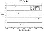
図4に表1から表4までの結果をまとめて示す。図4において、横軸は光透過層側から記録層にレーザ光を入射した場合(実施例1及び実施例2に相当)にはIL1/IL2を、PC基板側から記録層にレーザ光を入射した場合(実施例3及び実施例4に相当)にはIL2/IL1を、それぞれ表している。また、図4の縦軸は、ランド対応部分L’及びグルーブ対応部分G’のジッタの差の絶対値Δσを示している。図4から分かるように、記録によって反射率が低下するか増加するかに関わらず、光透過層側から記録層にレーザ光を入射した場合には、1<IL1/IL2<1.3、特に、1.1<IL1/IL2<1.3の場合に、また、PC基板側から記録層にレーザ光を入射した場合には、1<IL2/IL1<1.3、特に、1.1<IL2/IL1<1.3の場合に、ランド対応部分L’及びグルーブ対応部分G’のジッタのバランスが非常に良く取れていることが分かる。
図5から分るように、位相差がほぼ0の光ディスクを用いても、記録線密度が低ければランド及びグルーブの対応部分で分解能はほぼ同じであるので、低い密度で記録再生を行う場合には、本発明を用いても大きな効果は得られない。位相差がほぼ0の光ディスクに対して、ランド及びグルーブの対応部分で分解能が3dB以上異なる記録マークの長さは、例えばλ=405nm、NA=0.85の光ヘッドを用いた場合には、図5から分かるように0.18μm以下である。光ヘッドのビーム径が、λ/NAに比例することを考えると、光ディスク上に形成される最短のマーク長をMLとして、MLとλ/NAとの比a=NA・ML/λが記録密度の指標となる。この指標で図5を見直すと、分解能が3dB以上異なる記録密度では、a=0.38以下となる。aが0.25以下では光学的な回折限界を越えることになり信号そのものが得られなくなる。従って、本発明にかかる光学的情報記録媒体を用いることによって特性向上の効果が得られる記録密度は0.25<a<0.38の範囲に相当する。なお、図5には示していないが、NA=0.65の光ヘッドを用いた場合にも、分解能が3dB以上異なるのはaが0.38以下の場合であった。分解能が3dB異なる条件は、IS1/IL1とIS2/IL2との比が0.7となる条件と同一であり、本明細書で説明したように、ランド及びグルーブの対応部分で良好な特性が得られる条件に相当する。
【産業上の利用可能性】
以上説明したように、本発明によれば、記録層のランド対応部分及びグルーブ対応部分の双方に高い記録密度で記録を行うことが可能となるので、大容量の光学的情報記録媒体を得ることが可能となる。
【図面の簡単な説明】
図1は、本発明にかかる光学的情報記録媒体の部分拡大断面図である。
図2は、本発明にかかる光学的情報記録媒体に対する情報記録再生の方法及び装置の説明のための模式図である。
図3は、IL1/IL2と光学的な分解能との関係を説明する図である。
図4は、IL1/IL2又はIL2/IL1とランド対応部分又はグルーブ対応部分のジッタとの関係を説明する図である。
図5は、従来の光学的情報記録媒体におけるマーク長と信号振幅との関係を示す図である。【Technical field】
The present invention relates to an optical information recording medium on which information is recorded / reproduced using light such as a laser beam, and further to an optical information recording / reproducing method and an optical information recording / reproducing apparatus using the same. Optical information in which information is recorded in both the portion corresponding to the inside of the tracking guide groove and the portion corresponding to the portion between the adjacent guide grooves with respect to the recording layer provided on the surface of the substrate having the tracking guide groove. The present invention relates to a recording medium and an optical information recording / reproducing method and apparatus using the same.
[Background]
As optical information recording media for recording and reproducing information by laser light irradiation, MO (magneto-optical disk), CD-R (recordable compact disk), CD-RW (rewritable compact disk), DVD-R (recordable) In general, a DVD-RAM (rewritable digital versatile disk), a DVD-RW (rewritable digital versatile disk), or the like is generally known. As means for increasing the recording density in the optical information recording medium, flat portions (lands) between adjacent ones of the tracking guide grooves formed in a substantially circular shape in parallel with each other on the substrate surface, and the Land / groove recording is known in which recording is performed on the recording layer portion corresponding to both the inside (groove) of the guide groove (Japanese Patent Laid-Open Nos. 57-50330, 9-73665, and 9). -198716 publication, Unexamined-Japanese-Patent No. 10-64120 etc.).
In recent years, a technique for increasing the NA (numerical aperture) of the objective lens of an optical head constituting an apparatus for recording / reproducing information to about 0.85 has been proposed as a technique for increasing the recording density. Has been. By increasing the NA, it is possible to reduce the beam diameter when condensing the laser beam, and to record / reproduce a finer mark. When the NA is increased in this way, the recording layer is not irradiated with the laser beam through the substrate having a thickness of 0.6 to 1.2 mm as in the prior art, but on the recording layer of the optical information recording medium. Information can be recorded and reproduced by forming a light-transmitting layer having a thickness of about 0.1 mm and irradiating the recording layer on the substrate with laser light through the light-transmitting layer.
By combining these techniques, that is, by performing land / groove recording using an optical head having a high NA, it is conceivable to dramatically increase the recording density.
However, according to the knowledge of the inventors of the present application, when land / groove recording is performed using an optical head with a high NA, recording in the recording layer portion corresponding to the flat portion between the guide grooves and recording layer corresponding to the inside of the guide groove There is a problem that the optical resolution differs depending on the recording in the portion. Specifically, when recording is performed on the recording layer portion corresponding to the flat portion between the guide grooves, the mark length is reduced as compared with the case where recording is performed on the recording layer portion corresponding to the inside of the guide groove. As a result, the decrease in signal amplitude (based on the signal amplitude of the long mark) becomes more prominent.
FIG. 5 is a graph showing the relationship between the mark length on the horizontal axis and the signal amplitude on the vertical axis. This figure shows the result of recording on an optical disc having a phase change recording layer using an optical head having a wavelength of 405 nm and NA = 0.85. In the phase change type optical disk used in this experiment, the phase difference of the reflected light before and after recording is almost zero. When the line segment indicated by
This problem is not limited to the case where information is recorded on and reproduced from the recording layer through the light transmission layer, and information is recorded on and reproduced from the recording layer by irradiating laser light from the back side of the substrate as in the case of a conventional DVD. Even in such a case, it becomes remarkable as the recording density is increased, that is, as the shortest mark length recorded on the disk is shortened. The decrease in the signal amplitude at the short mark is significant not depending on whether the recording is performed on the corresponding portion between the guide groove flat portions or on the inner portion of the guide groove, but on the incident direction of the laser light. . In other words, when the recording layer is irradiated with laser light through the light transmission layer, the signal amplitude of the short mark recorded in the portion corresponding to the flat portion between the guide grooves is significantly reduced. Further, when the laser beam is irradiated through the substrate, the signal amplitude of the short mark recorded in the corresponding portion inside the guide groove is significantly reduced.
DISCLOSURE OF THE INVENTION
The present invention has been made in view of the above problems, and when recording at a high recording density on both the recording layer portion corresponding to the flat portion between the guide grooves and the recording layer portion corresponding to the inside of the guide groove, The recording and reproducing characteristics of the portion corresponding to the flat portion between the guide grooves and the portion corresponding to the inside of the guide groove are made substantially equal, thereby increasing the track density and at the same time improving the recording linear density and enabling recording at a high density. An object is to provide an optical information recording medium.
According to the present invention, the object as described above is achieved.
Information is recorded / reproduced by irradiating light in a spot shape, and at least a recording layer and a light transmission layer are provided in this order on a substrate having a guide groove for tracking the spot light. The recording layer is irradiated with the light in a spot shape from the transmissive layer side, and corresponds to the first portion of the recording layer corresponding to the flat portion between the guide grooves adjacent to each other and the inside of the guide groove. An optical information recording medium for recording on both of the second portions of the recording layer is provided having the following characteristics:
(1) The reflectance of the recording layer is reduced by performing recording, and the difference Δφ = φa−φc between the phase φa of the reflected light after recording and the phase φc of the reflected light before recording is 0 ° <Δφ ≦ 15 ° An optical information recording medium characterized by satisfying the relationship:
(2) The recording layer has a reflectivity increased by recording, and the difference Δφ = φa−φc between the phase φa of the reflected light after recording and the phase φc of the reflected light before recording is −15 ° ≦ Δφ <0. An optical information recording medium characterized by satisfying the relationship of °.
In addition, according to the present invention, the object as described above is achieved.
Information is recorded / reproduced by irradiating light in a spot form, and at least a recording layer is provided on a substrate having a guide groove for tracking the spot-like light, and the recording layer is provided from the substrate side. Irradiating the light in a spot shape with respect to the first portion of the recording layer corresponding to the flat portion between the adjacent guide grooves and the second portion of the recording layer corresponding to the inside of the guide groove An optical information recording medium for recording on both parts, having the following characteristics:
(3) The reflectance of the recording layer is reduced by performing recording, and the difference Δφ = φa−φc between the phase φa of the reflected light after recording and the phase φc of the reflected light before recording is 0 ° <Δφ ≦ 15 ° An optical information recording medium characterized by satisfying the relationship:
(4) The recording layer has a reflectivity increased by recording, and the difference Δφ = φa−φc between the phase φa of the reflected light after recording and the phase φc of the reflected light before recording is −15 ° ≦ Δφ <0. An optical information recording medium characterized by satisfying the relationship of °.
Further, according to the present invention, the following optical information recording / reproducing method is provided to achieve the above object:
Above (1)Or (2) Optical information recording mediumCorresponding to the flat portion between the guide grooves adjacent to each other. A first portion of the recording layer; andOf the recording layer corresponding to the inside of the guide groove. For both of the second partAnd Spot length of light to mark length nT to mT(Here, T is a unit length, n and m are integers of 1 or more, and n <m) The recording mark is formed and recorded,Amplitude of reproduction signal from longest recording mark of mark length mT recorded in the first part IL1 and the aboveAmplitude of reproduction signal from longest recording mark of mark length mT recorded in the second portion An optical information recording / reproducing method characterized in that IL2 satisfies a relationship of 1 <(IL1 / IL2) <1.3;
the above(1) or Optical information recording medium (2)Corresponding to the flat portion between the guide grooves adjacent to each other. A first portion of the recording layer; andOf the recording layer corresponding to the inside of the guide groove. For both of the second partAnd Spot length of light to mark length nT to mT(Here, T is a unit length, n and m are integers of 1 or more, and n <m) The recording mark is formed and recorded,Amplitude of reproduction signal from longest recording mark of mark length mT recorded in the first part IL1, saidAmplitude of reproduction signal from shortest recording mark of mark length nT recorded in the first portion IS1, saidAmplitude of reproduction signal from longest recording mark of mark length mT recorded in the second portion IL2 andAmplitude of reproduction signal from shortest recording mark of mark length nT recorded in the second portion An optical information recording / reproducing method characterized in that IS2 satisfies a relationship of 0.7 <(IS1 / IL1) / (IS2 / IL2) <1;
the above(1) or (3) A recording mark having a mark length of nT to mT is formed by irradiating both the first part and the second part of the recording layer of the optical information recording medium in a spot shape to reduce the reflectance. An optical information recording / reproducing method, wherein recording is performed so that Δφ satisfies a relationship of 0 ° <Δφ ≦ 15 °;
the above(2) or (4) A recording mark having a mark length of nT to mT is formed by irradiating both the first portion and the second portion of the recording layer of the optical information recording medium in a spot shape to increase the reflectance. An optical information recording / reproducing method, wherein recording is performed so that Δφ satisfies a relationship of −15 ° ≦ Δφ <0 °;
the above(3) or (4) Optical information recording mediumCorresponding to the flat portion between the guide grooves adjacent to each other. A first portion of the recording layer; andOf the recording layer corresponding to the inside of the guide groove. For both of the second partAnd Spot length of light to mark length nT to mT(Here, T is a unit length, n and m are integers of 1 or more, and n <m) The recording mark is formed and recorded,Amplitude of reproduction signal from longest recording mark of mark length mT recorded in the first part IL1 and the aboveAmplitude of reproduction signal from longest recording mark of mark length mT recorded in the second portion An optical information recording / reproducing method, wherein IL2 satisfies a relationship of 1 <(IL2 / IL1) <1.3;
the above(3) or (4) Optical information recording mediumCorresponding to the flat portion between the guide grooves adjacent to each other. A first portion of the recording layer; andOf the recording layer corresponding to the inside of the guide groove. For both of the second partAnd Spot length of light to mark length nT to mT(Here, T is a unit length, n and m are integers of 1 or more, and n <m) The recording mark is formed and recorded,Amplitude of reproduction signal from longest recording mark of mark length mT recorded in the first part IL1, saidAmplitude of reproduction signal from shortest recording mark of mark length nT recorded in the first portion IS1, saidAmplitude of reproduction signal from longest recording mark of mark length mT recorded in the second portion IL2 andAmplitude of reproduction signal from shortest recording mark of mark length nT recorded in the second portion An optical information recording / reproducing method characterized in that IS2 satisfies a relationship of 0.7 <(IS2 / IL2) / (IS1 / IL1) <1;
Above (1) ~Any of (4) Using an optical information recording medium, both the first portion and the second portion of the recording layer are irradiated with light in a spot shape using an objective lens to form a recording mark, and recording is performed here. 0.25 <NA · ML / λ <0.38 is established, where λ is the wavelength of the light, NA is the numerical aperture of the objective lens, and ML is the shortest mark length of the recording mark. An optical information recording / reproducing method.
Furthermore, according to the present invention, in order to achieve the above object, both the first portion and the second portion of the recording layer of the optical information recording medium are irradiated with light in a spot shape. An optical information recording / reproducing apparatus including an optical head is provided. The optical head has an objective lens having a numerical aperture of 0.8 to 0.9, for example. In addition, the optical head includes, for example, a laser light source such as a semiconductor laser that emits the light having the wavelength λ and an objective lens having a numerical aperture NA. Here, the shortest mark length of the recording mark formed by the light irradiation The recording mark is formed so that the optical head satisfies 0.25 <NA · ML / λ <0.38.
BEST MODE FOR CARRYING OUT THE INVENTION
Hereinafter, embodiments of the present invention will be described with reference to the drawings.
FIG. 1 is a partially enlarged sectional view showing an embodiment of an optical information recording medium according to the present invention. On the surface (upper surface) of the disc-shaped support substrate 1 having a thickness of about 1.2 mm, a tracking guide groove extending in a substantially circular shape is formed around the center of the substrate, and between the adjacent guide grooves. Is formed with a flat portion (land) L. The inside (bottom part) of the tracking guide groove is a groove G in particular. The depth (groove depth) of the groove G with respect to the land L is D. The width of the land L and the width of the groove G are typically substantially equal, and preferably within an error of 10%. The arrangement pitch of the grooves G is, for example, 0.5 to 1.2 μm.
A
As the
If necessary, a metal layer as a reflective film may be provided between the upper surface of the substrate 1 and the
Information recording / reproduction is performed on the groove corresponding portion G ′ and the land corresponding portion L ′ of the
FIG. 2 is a schematic diagram for explaining an embodiment of an information recording / reproducing method and apparatus for the optical information recording medium as described above. The optical
In addition, this invention is not limited to what irradiates a laser beam from the
Thus, in the present invention, when recording / reproducing information on the
{1} When a recording mark having a mark length nT to mT (T is a unit length, n and m are integers of 1 or more and n <m: the same applies below) is formed using a certain modulation method, the land corresponding portion L ′ And the reproduction signal amplitude IL2 of the longest mark mT recorded in the groove corresponding portion G ′ satisfies the relationship 1 <(IL1 / IL2) <1.3. This modulation method is the same as the modulation method in the case of recording / reproducing information with respect to a conventional optical information recording medium, for example, (1-7) modulation method, and is well known in the art. Any of the known modulation schemes can be applied.
{2} When recording marks of nT to mT are formed using a certain modulation method, the reproduction signal amplitude IL1 of the longest mark mT and the reproduction signal amplitude IS1 of the shortest mark nT recorded in the land corresponding portion L ′, and the groove corresponding portion G The reproduction signal amplitude IL2 of the longest mark mT recorded in 'and the reproduction signal amplitude IS2 of the shortest mark nT satisfy the relationship of 0.7 <(IS1 / IL1) / (IS2 / IL2) <1.
{3} The
{4} The
The inventors of the present invention have an optical resolution when recording is performed on the land corresponding portion L ′ using an optical head having a high NA (for example, 0.6 to 0.9, particularly 0.8 to 0.9). It was found that the length of the reproduction signal amplitude IL1 of the long mark recorded in the land corresponding portion L ′ and the length of the reproduction signal amplitude IL2 of the long mark recorded in the groove corresponding portion G ′ vary greatly. In FIG. 3, the horizontal axis represents the ratio IL1 / IL2, the vertical axis represents the resolution, and when recorded in the groove corresponding portion (reference numeral 29) and when recorded in the land corresponding portion L ′ (reference numeral 30), It is a graph which shows the relationship between ratio of IL1 / IL2, and resolution | decomposability. In FIG.FIG. The resolution is defined as the ratio of the reproduction signal amplitude for the mark having a length of 0.13 μm and the reproduction signal amplitude for the mark having a length of 0.67 μm. As shown in FIG. 3, the optical resolution (reference numeral 30) when recording is performed on the land corresponding portion L ′ using an optical head having a high NA is the same as that of the long mark recorded on the land corresponding portion L ′. This greatly varies depending on the ratio IL1 / IL2 between the reproduction signal amplitude IL1 and the reproduction signal amplitude IL2 of the long mark recorded in the groove corresponding portion G ′. On the other hand, the optical resolution (reference numeral 29) when recording is performed on the groove corresponding portion G ′ hardly depends on the ratio IL1 / IL2 of IL1 and IL2. Therefore, in order to match the optical resolution between the land-corresponding portion and the groove-corresponding portion as much as possible, the ratio IL1 / IL2 of IL1 and IL2 may be regulated as appropriate. In other words, IL1 / IL2 is set to be greater than 1 (IL1 is set to be greater than IL2) in order to match the optical resolution between the land-corresponding portion and the groove-corresponding portion. However, since it is difficult to increase only the signal amplitude of IL1 without changing the signal amplitude of IL2, it is necessary to decrease IL2 in order to increase IL1 / IL2. Thus, if IL2 is made small, signal quality itself will fall. For this reason, IL1 / IL2 is made smaller than 1.3. Therefore, 1 <(IL1 / IL2) <1.3.
Further, the ratio IS1 / IL1 of the reproduction signal amplitude IS1 of the shortest mark to the reproduction signal amplitude IL1 of the longest mark recorded in the land corresponding portion L ′ and the reproduction signal amplitude IL2 of the longest mark recorded in the groove corresponding portion G ′. Even when the ratio IS2 / IL2 of the reproduction signal amplitude IS2 of the shortest mark satisfies the relationship 0.7 <(IS1 / IL1) / (IS2 / IL2) <1, the groove is similar to the case shown in FIG. The difference in resolution between the recording in the corresponding portion G ′ and the recording in the land corresponding portion L ′ is extremely small.
Similarly, the value of IL1 / IL2 can be changed by changing the difference Δφ = φa−φc between the phase φa of the reflected light after recording and the phase φc of the reflected light before recording. In the case where the
Further, in the case where the
Therefore, when recording / reproducing information by irradiating the
On the other hand, unlike FIG. 1, in the case where information is recorded / reproduced by irradiating laser light from the back surface (lower surface) of the substrate 1, contrary to FIG. 5, a reproduction signal of a short mark in the groove corresponding portion G ′. Since the decrease in amplitude becomes significant, in the present invention, the following{5} Thru{8} It has one of the following characteristics.
{5} When a recording mark of nT to mT is formed using a certain modulation method, the reproduction signal amplitude IL1 of the longest mark mT recorded in the land corresponding portion L ′ and the reproduction of the longest mark mT recorded in the groove corresponding portion G ′ The signal amplitude IL2 satisfies the relationship 1 <(IL2 / IL1) <1.3.
{6 When a recording mark of nT to mT is formed using a certain modulation method, the reproduction signal amplitude IL1 of the longest mark mT and the reproduction signal amplitude IS1 of the shortest mark nT recorded in the land corresponding portion L ′, and the groove corresponding portion The reproduction signal amplitude IL2 of the longest mark mT and the reproduction signal amplitude IS2 of the shortest mark nT recorded in G ′ satisfy the relationship 0.7 <(IS2 / IL2) / (IS1 / IL1) <1.
{7} The
{8} The
When the laser light is incident on the
Examples of the present invention will be described below together with comparative examples outside the scope of the present invention to further explain the effects of the present invention.
Example 1
A disk-shaped PC substrate with a thickness of 1.1 mm is used as the substrate, and an Al reflective film with a thickness of 100 nm and a ZnS-SiO with a thickness of 15 nm are formed on the land / groove forming surface of the substrate.2 Dielectric layer, GeSbTe recording layer with a thickness of 15 nm, ZnS-SiO with a thickness of 40 to 85 nm2 A dielectric layer was formed by sputtering. On top of that, a PC film having a thickness of 0.1 mm as a light transmission layer was bonded with an ultraviolet curable resin.
After the disk (recording medium) was initialized (crystallized), it was rotated at a linear velocity of 5.1 m / s, and an optical head having a wavelength of 405 nm and NA = 0.85 was used, from the light transmission layer side. Laser characteristics were irradiated, recording was performed on both the land corresponding portion L ′ and the groove corresponding portion G ′ under a linear density condition of 0.116 μm / bit, and the reproduction characteristics were measured. Since (1-7) modulation was used as the modulation method, the mark length of the longest mark was 8T, and the mark length of the shortest mark was 2T. IL1 and IL2 correspond to the amplitude of the 8T reproduction signal, and IS1 and IS2 correspond to the amplitude of the 2T reproduction signal.
Table 1 shows ZnS-SiO on the recording layer.2 The relationship between the optical characteristics and the recording / reproducing characteristics when the film thickness of the dielectric layer is changed is shown. Since the recording layer is in a crystalline state before recording and is in an amorphous state after recording, φa is a phase of reflected light when the recording layer is in an amorphous state, and φc is a crystalline state in the recording layer. This corresponds to the phase of the reflected light.
Note that the recording power is set to a power that minimizes the second-order harmonic distortion of the 8T reproduction signal in each of the land corresponding portion L ′ and the groove corresponding portion G ′, but as shown in Table 1, the land corresponding portion L ′. And the groove-corresponding portion G ′ had almost the same recording power, and the difference was 5% or less.
[Table 1]
(Example 2)
A disk-shaped PC substrate with a thickness of 1.1 mm is used as the substrate, and an Al reflective film with a thickness of 100 nm and a ZnS-SiO with a thickness of 25 nm are formed on the land / groove forming surface of the substrate.2 Dielectric layer, GeSbTe recording layer with a thickness of 15 nm, ZnS-SiO with a thickness of 25 nm2 Dielectric layer, 30 nm thick SiO2 Dielectric layer and ZnS-SiO with a thickness of 50-75 nm2 Dielectric layers were sequentially stacked and formed by sputtering, and a PC film having a thickness of 0.1 mm as a light transmission layer was adhered thereon with an ultraviolet curable resin.
After initializing (crystallizing) the disk, the disk was rotated at a linear velocity of 5.1 m / s, and a laser beam was irradiated from the light transmission layer side using an optical head having a wavelength of 405 nm and NA = 0.85. Then, recording was performed on both the land corresponding portion L ′ and the groove corresponding portion G ′ under a linear density condition of 0.116 μm / bit, and the reproduction characteristics were measured. Since (1-7) modulation was used as the modulation method, the mark length of the longest mark was 8T, and the mark length of the shortest mark was 2T. IL1 and IL2 correspond to the amplitude of the 8T reproduction signal, and IS1 and IS2 correspond to the amplitude of the 2T reproduction signal.
Table 2 shows the top ZnS-SiO layer.2 The relationship between the optical characteristics and the recording / reproducing characteristics when the film thickness of the dielectric layer is changed is shown. Since the recording layer is in a crystalline state before recording and is in an amorphous state after recording, φa is a phase of reflected light when the recording layer is in an amorphous state, and φc is a crystalline state in the recording layer. This corresponds to the phase of the reflected light.
In this embodiment, the recording power is set to the power with the best symmetry (symmetry) of the eye pattern when the random signal is recorded in each of the land corresponding portion L ′ and the groove corresponding portion G ′. As shown, the land-corresponding portion L ′ and the groove-corresponding portion G ′ have almost the same recording power, and the difference between them is 5% or less.
[Table 2]
(Example 3)
A disk-shaped PC substrate having a thickness of 0.6 mm is used as the substrate, and ZnS-SiO having a thickness of 40 to 85 nm is formed on the land / groove forming surface of the substrate.2 Dielectric layer, GeSbTe recording layer with a thickness of 15 nm, ZnS-SiO with a thickness of 15 nm2 A dielectric layer and an Al reflective film having a thickness of 100 nm were sequentially formed by sputtering. A glass substrate having a thickness of 0.6 mm was laminated thereon with an ultraviolet curable resin.
After initializing (crystallizing) the disk (recording medium), it was rotated at a linear velocity of 3.5 m / s, and a laser was applied from the back of the PC board using an optical head having a wavelength of 405 nm and NA = 0.65. Light was irradiated, recording was performed on both the land corresponding part L ′ and the groove corresponding part G ′ under a linear density condition of 0.16 μm / bit, and the reproduction characteristics were measured. Since (1-7) modulation was used as the modulation method, the mark length of the longest mark was 8T, and the mark length of the shortest mark was 2T. IL1 and IL2 correspond to the amplitude of the 8T reproduction signal, and IS1 and IS2 correspond to the amplitude of the 2T reproduction signal.
Table 3 shows ZnS-SiO on PC substrate.2 The relationship between the optical characteristics and the recording / reproducing characteristics when the film thickness of the dielectric layer is changed is shown. Since the recording layer is in a crystalline state before recording and is in an amorphous state after recording, φa is a phase of reflected light when the recording layer is in an amorphous state, and φc is a crystalline state in the recording layer. This corresponds to the phase of the reflected light.
The recording power is set to a power that minimizes the second-order harmonic distortion of the 8T reproduction signal in each of the land corresponding portion L ′ and the groove corresponding portion G ′, but as shown in Table 3, the land corresponding portion L ′. And the groove-corresponding portion G ′ had almost the same recording power, and the difference was 5% or less.
[Table 3]
(Example 4)
A disk-shaped PC substrate having a thickness of 0.6 mm is used as the substrate, and ZnS-SiO having a thickness of 50 to 75 nm is formed on the land / groove forming surface of the substrate.2 Dielectric layer, 30 nm thick SiO2 Dielectric layer, ZnS-SiO with a thickness of 25 nm2 Dielectric layer, GeSbTe recording layer with a thickness of 15 nm, ZnS-SiO with a thickness of 25 nm2 A dielectric layer and an Al reflective film having a thickness of 100 nm were sequentially formed by sputtering, and a glass substrate having a thickness of 0.6 mm was laminated thereon with an ultraviolet curable resin.
After initializing (crystallizing) the disk, the disk was rotated at a linear velocity of 3.5 m / s, and a laser beam was irradiated from the back of the PC board using an optical head with a wavelength of 405 nm and NA = 0.65. Then, recording was performed on both the land corresponding portion L ′ and the groove corresponding portion G ′ under a linear density condition of 0.16 μm / bit, and the reproduction characteristics were measured. Since (1-7) modulation was used as the modulation method, the mark length of the longest mark was 8T, and the mark length of the shortest mark was 2T. IL1 and IL2 correspond to the amplitude of the 8T reproduction signal, and IS1 and IS2 correspond to the amplitude of the 2T reproduction signal.
Table 4 shows ZnS-SiO directly above the substrate.2 The relationship between the optical characteristics and the recording / reproducing characteristics when the film thickness of the dielectric layer is changed is shown. Since the recording layer is in a crystalline state before recording and is in an amorphous state after recording, φa is a phase of reflected light when the recording layer is in an amorphous state, and φc is a crystalline state in the recording layer. This corresponds to the phase of the reflected light.
In this embodiment, the recording power is set to the power with the best symmetry (symmetry) of the eye pattern when the random signal is recorded in each of the land corresponding portion L ′ and the groove corresponding portion G ′. As shown, the recording power is almost the same in the land corresponding part L ′ and the groove corresponding part G ′, and the difference is 5% or less.
[Table 4]
FIG. 4 summarizes the results from Table 1 to Table 4. In FIG. 4, the horizontal axis indicates IL1 / IL2 when laser light is incident on the recording layer from the light transmission layer side (corresponding to Example 1 and Example 2), and laser light is incident on the recording layer from the PC substrate side. In this case (corresponding to Example 3 and Example 4), IL2 / IL1 is shown. The vertical axis in FIG. 4 indicates the absolute value Δσ of the difference in jitter between the land corresponding portion L ′ and the groove corresponding portion G ′. As can be seen from FIG. 4, when laser light is incident on the recording layer from the light transmission layer side regardless of whether the reflectance is decreased or increased by recording, 1 <IL1 / IL2 <1.3, particularly , 1.1 <IL1 / IL2 <1.3, and when laser light is incident on the recording layer from the PC substrate side, 1 <IL2 / IL1 <1.3, especially 1.1 < It can be seen that when IL2 / IL1 <1.3, the balance of the jitter corresponding to the land corresponding portion L ′ and the groove corresponding portion G ′ is very well balanced.
As can be seen from FIG. 5, even when an optical disc having a phase difference of approximately 0 is used, the resolution is substantially the same at the corresponding portions of the land and groove if the recording linear density is low. Even if the present invention is used, a great effect cannot be obtained. For an optical disk having a phase difference of almost 0, the length of a recording mark having a resolution different by 3 dB or more at the corresponding part of the land and groove is, for example, when an optical head with λ = 405 nm and NA = 0.85 is used. As can be seen from FIG. 5, it is 0.18 μm or less. Considering that the beam diameter of the optical head is proportional to λ / NA, where ML is the shortest mark length formed on the optical disk, the ratio of ML to λ / NA, a = NA · ML / λ, is the recording density. It becomes an index. When reviewing FIG. 5 with this index, a = 0.38 or less at a recording density with a resolution different by 3 dB or more. If a is 0.25 or less, the optical diffraction limit is exceeded, and the signal itself cannot be obtained. Therefore, the recording density at which the effect of improving the characteristics can be obtained by using the optical information recording medium according to the present invention corresponds to the range of 0.25 <a <0.38. Although not shown in FIG. 5, even when an optical head with NA = 0.65 is used, the resolution differs by 3 dB or more when a is 0.38 or less. The condition where the resolution is different by 3 dB is the same as the condition where the ratio of IS1 / IL1 and IS2 / IL2 is 0.7. As described in this specification, good characteristics can be obtained at the corresponding portions of the land and the groove. It corresponds to the condition to be.
[Industrial applicability]
As described above, according to the present invention, it is possible to perform recording at a high recording density on both the land-corresponding portion and the groove-corresponding portion of the recording layer, thereby obtaining a large-capacity optical information recording medium. Is possible.
[Brief description of the drawings]
FIG. 1 is a partially enlarged sectional view of an optical information recording medium according to the present invention.
FIG. 2 is a schematic view for explaining an information recording / reproducing method and apparatus for an optical information recording medium according to the present invention.
FIG. 3 is a diagram illustrating the relationship between IL1 / IL2 and optical resolution.
FIG. 4 is a diagram for explaining the relationship between IL1 / IL2 or IL2 / IL1 and the jitter corresponding to the land corresponding portion or the groove corresponding portion.
FIG. 5 is a diagram showing the relationship between mark length and signal amplitude in a conventional optical information recording medium.
Claims (11)
Translated fromJapanese前記記録層は記録を行うことにより前記波長を有するレーザ光に対する反射率が低下し、かつ、前記波長を有するレーザ光に対する記録後の反射光の位相φaと前記波長を有するレーザ光に対する記録前の反射光の位相φcとの差Δφ=φa−φcが0°<Δφ≦15°の関係を満たすことを特徴とする光学的情報記録媒体。Information is recorded / reproduced by irradiatinglaser light with a wavelength of 390-440 nm in a spot shape, and at least a recording layer and a light transmission layer are provided on the substrate having a guide groove for tracking the spot light. A first portion of the recording layer that is provided in order and corresponds to a flat portion between the guide grooves adjacent to each other by irradiating the recording layer with the light in a spot shape from the light transmitting layer side And an optical information recording medium for recording on both the second portion of the recording layer corresponding to the inside of the guide groove,
The recording layer reflectanceto the laser light having the wavelength is reduced by performing the recording and before recordingwith respect to the laser beam having the wavelength and the phase φa of the reflected light after recordingwith respect to the laser beam having the wavelength An optical information recording medium characterized in that a difference Δφ = φa−φc with respect to a phase φc of reflected light satisfies a relationship of 0 ° <Δφ ≦ 15 °.
前記記録層は記録を行うことにより前記波長を有するレーザ光に対する反射率が増加し、かつ、前記波長を有するレーザ光に対する記録後の反射光の位相φaと前記波長を有するレーザ光に対する記録前の前記波長を有するレーザ光に対する反射光の位相φcとの差Δφ=φa−φcが−15°≦Δφ<0°の関係を満たすことを特徴とする光学的情報記録媒体。Information is recorded / reproduced by irradiatinglaser light with a wavelength of 390-440 nm in a spot shape, and at least a recording layer and a light transmission layer are provided on the substrate having a guide groove for tracking the spot light. A first portion of the recording layer that is provided in order and corresponds to a flat portion between the guide grooves adjacent to each other by irradiating the recording layer with the light in a spot shape from the light transmitting layer side And an optical information recording medium for recording on both the second portion of the recording layer corresponding to the inside of the guide groove,
The recording layer reflectanceto the laser light having the wavelength is increased by performing the recording and before recordingwith respect to the laser beam having the wavelength and the phase φa of the reflected light after recordingwith respect to the laser beam having the wavelength An optical information recording medium,wherein the difference Δφ = φa−φc between the reflected light and the phase φc of thelaser beam having the wavelength satisfies a relationship of −15 ° ≦ Δφ <0 °.
前記記録層は記録を行うことにより前記波長を有するレーザ光に対する反射率が低下し、かつ、前記波長を有するレーザ光に対する記録後の反射光の位相φaと前記波長を有するレーザ光に対する記録前の反射光の位相φcとの差Δφ=φa−φcが0°<Δφ≦15°の関係を満たすことを特徴とする光学的情報記録媒体。Information is recorded / reproduced by irradiatinglaser light with a wavelength of 390-440 nm in a spot shape, and at least a recording layer is provided on a substrate having a guide groove for tracking the spot light, The recording layer is irradiated with the light in a spot shape from the substrate side, and corresponds to the first portion of the recording layer corresponding to the flat portion between the guide grooves adjacent to each other and the inside of the guide groove. An optical information recording medium for recording on both of the second portions of the recording layer,
The recording layer reflectanceto the laser light having the wavelength is reduced by performing the recording and before recordingwith respect to the laser beam having the wavelength and the phase φa of the reflected light after recordingwith respect to the laser beam having the wavelength An optical information recording medium characterized in that a difference Δφ = φa−φc with respect to a phase φc of reflected light satisfies a relationship of 0 ° <Δφ ≦ 15 °.
前記記録層は記録を行うことにより前記波長を有するレーザ光に対する反射率が増加し、かつ、前記波長を有するレーザ光に対する記録後の反射光の位相φaと前記波長を有するレーザ光に対する記録前の反射光の位相φcとの差Δφ=φa−φcが−15°≦Δφ<0°の関係を満たすことを特徴とする光学的情報記録媒体。Information is recorded / reproduced by irradiatinglaser light with a wavelength of 390-440 nm in a spot shape, and at least a recording layer is provided on a substrate having a guide groove for tracking the spot light, The recording layer is irradiated with the light in a spot shape from the substrate side, and corresponds to the first portion of the recording layer corresponding to the flat portion between the guide grooves adjacent to each other and the inside of the guide groove. An optical information recording medium for recording on both of the second portions of the recording layer,
The recording layer reflectanceto the laser light having the wavelength is increased by performing the recording and before recordingwith respect to the laser beam having the wavelength and the phase φa of the reflected light after recordingwith respect to the laser beam having the wavelength An optical information recording medium characterized in that a difference Δφ = φa−φc with respect to a phase φc of reflected light satisfies a relationship of −15 ° ≦ Δφ <0 °.
Applications Claiming Priority (3)
| Application Number | Priority Date | Filing Date | Title |
|---|---|---|---|
| JP2002115448 | 2002-04-17 | ||
| JP2002115448 | 2002-04-17 | ||
| PCT/JP2003/004882WO2003088224A1 (en) | 2002-04-17 | 2003-04-17 | Method and apparatus for recording/reproducing optical information |
Publications (2)
| Publication Number | Publication Date |
|---|---|
| JPWO2003088224A1 JPWO2003088224A1 (en) | 2005-08-25 |
| JP4211607B2true JP4211607B2 (en) | 2009-01-21 |
Family
ID=29243424
Family Applications (1)
| Application Number | Title | Priority Date | Filing Date |
|---|---|---|---|
| JP2003585076AExpired - Fee RelatedJP4211607B2 (en) | 2002-04-17 | 2003-04-17 | Optical information recording and reproducing method and apparatus |
Country Status (6)
| Country | Link |
|---|---|
| US (2) | US7280462B2 (en) |
| EP (1) | EP1501086A4 (en) |
| JP (1) | JP4211607B2 (en) |
| CN (2) | CN101430899A (en) |
| AU (1) | AU2003227408A1 (en) |
| WO (1) | WO2003088224A1 (en) |
Families Citing this family (4)
| Publication number | Priority date | Publication date | Assignee | Title |
|---|---|---|---|---|
| US7177262B2 (en)* | 2002-04-19 | 2007-02-13 | Victor Company Of Japan, Ltd. | Reproducing system and corresponding information recording medium having wobbled land portions |
| KR101049985B1 (en)* | 2003-08-07 | 2011-07-19 | 파나소닉 주식회사 | Optical information recording medium, its manufacturing method, manufacturing apparatus, recording / reproducing method, and recording / reproducing apparatus |
| KR100604839B1 (en)* | 2004-03-10 | 2006-07-26 | 삼성전자주식회사 | A recordable optical storage medium capable of recording information without damaging data and a method and apparatus for recording data on the optical storage medium |
| US20100232277A1 (en)* | 2006-02-02 | 2010-09-16 | Taiyo Yuden Co., Ltd. | Optical Information Recording Medium, Manufacturing Method Thereof, and Recording Method Thereof |
Family Cites Families (20)
| Publication number | Priority date | Publication date | Assignee | Title |
|---|---|---|---|---|
| JPS5750330A (en) | 1980-09-11 | 1982-03-24 | Matsushita Electric Ind Co Ltd | Optical recording and reproducing device |
| JP2773606B2 (en) | 1993-10-22 | 1998-07-09 | 松下電器産業株式会社 | Optical disk drive |
| US5568461A (en)* | 1994-04-20 | 1996-10-22 | Matsushita Electric Industrial Co., Ltd. | Optical information recording and reproducing apparatus |
| JP3177116B2 (en)* | 1994-04-20 | 2001-06-18 | 松下電器産業株式会社 | Optical information recording medium and optical recording / reproducing device |
| JP3284744B2 (en)* | 1994-04-20 | 2002-05-20 | 松下電器産業株式会社 | Optical information recording medium |
| US5581539A (en)* | 1994-08-12 | 1996-12-03 | Mitsubishi Chemical Corporation | Optical recording medium |
| JPH09167348A (en) | 1994-11-10 | 1997-06-24 | Matsushita Electric Ind Co Ltd | Optical disc recording method, recording device, reproducing method, and reproducing device |
| JPH0973665A (en) | 1995-06-30 | 1997-03-18 | Toray Ind Inc | Optical recording medium and recording method thereof |
| JPH09198716A (en) | 1996-01-19 | 1997-07-31 | Nikon Corp | optical disk |
| JPH09265658A (en) | 1996-03-29 | 1997-10-07 | Toray Ind Inc | Optical recording medium |
| JPH1083536A (en) | 1996-06-07 | 1998-03-31 | Nikon Corp | Information recording / reproducing device |
| JPH1064120A (en) | 1996-08-20 | 1998-03-06 | Toshiba Corp | Land / groove recording information recording medium |
| WO1999000794A1 (en)* | 1997-06-27 | 1999-01-07 | Sony Corporation | Optical recording medium and optical disk device |
| JPH11134720A (en) | 1997-08-28 | 1999-05-21 | Matsushita Electric Ind Co Ltd | Optical information recording medium and recording / reproducing method therefor |
| EP0957477A3 (en)* | 1998-05-15 | 2003-11-05 | Matsushita Electric Industrial Co., Ltd. | Optical information recording medium, recording and reproducing method therefor and optical information recording and reproduction apparatus |
| TW479253B (en)* | 1998-12-17 | 2002-03-11 | Konishiroku Photo Ind | Objective lens for correcting chromatic aberration for use in recording toor reproducing from optical information recording medium and optical pickup apparatus therewith |
| EP1158504B1 (en)* | 1999-09-08 | 2005-12-21 | Mitsubishi Chemical Corporation | Rewritable compact disk and method for manufacturing the same |
| JP2002008269A (en)* | 2000-06-22 | 2002-01-11 | Sony Corp | Optical recording medium and manufacturing method thereof |
| JP2002092962A (en)* | 2000-09-20 | 2002-03-29 | Nec Corp | Optical information recording medium |
| JP2002352475A (en)* | 2001-03-22 | 2002-12-06 | Victor Co Of Japan Ltd | Information recording medium |
- 2003
- 2003-04-17WOPCT/JP2003/004882patent/WO2003088224A1/enactiveApplication Filing
- 2003-04-17AUAU2003227408Apatent/AU2003227408A1/ennot_activeAbandoned
- 2003-04-17CNCNA2008101733447Apatent/CN101430899A/enactivePending
- 2003-04-17CNCN038139154Apatent/CN1662964A/enactivePending
- 2003-04-17EPEP03717621Apatent/EP1501086A4/ennot_activeWithdrawn
- 2003-04-17JPJP2003585076Apatent/JP4211607B2/ennot_activeExpired - Fee Related
- 2003-04-17USUS10/511,668patent/US7280462B2/ennot_activeExpired - Fee Related
- 2007
- 2007-07-27USUS11/829,373patent/US20070263527A1/ennot_activeAbandoned
Also Published As
| Publication number | Publication date |
|---|---|
| EP1501086A4 (en) | 2008-11-26 |
| US7280462B2 (en) | 2007-10-09 |
| US20050157633A1 (en) | 2005-07-21 |
| CN1662964A (en) | 2005-08-31 |
| EP1501086A1 (en) | 2005-01-26 |
| WO2003088224A1 (en) | 2003-10-23 |
| WO2003088224A8 (en) | 2004-02-19 |
| CN101430899A (en) | 2009-05-13 |
| AU2003227408A1 (en) | 2003-10-27 |
| US20070263527A1 (en) | 2007-11-15 |
| JPWO2003088224A1 (en) | 2005-08-25 |
Similar Documents
| Publication | Publication Date | Title |
|---|---|---|
| US6018510A (en) | Phase change recording medium for allowing a tracking servo control based on a differential phase detection tracking method | |
| WO2003102932A1 (en) | Laser beam power modulation pattern decision method, device for recording data onto optical recording medium, and optical recording medium | |
| WO2012014429A1 (en) | Optical information recording medium and drive device | |
| US20050157635A1 (en) | Optical recording medium with high density track pitch and optical disk drive for recording and playback of the same | |
| CN101211605B (en) | Optical disc media and optical disc devices | |
| JP2002237090A (en) | High density optical recording medium and method for recording data on this high density optical recording medium | |
| US20070263527A1 (en) | Method and apparatus for recording/reproducing optical information | |
| JPH09320117A (en) | Optical disk | |
| CN100403423C (en) | Optical information recording medium, and optical information recording/reproducing method and apparatus using the same | |
| JP2002092962A (en) | Optical information recording medium | |
| US7336596B2 (en) | Optical storage medium | |
| US20090290476A1 (en) | Optical information recording medium, optical information recording/reproducing apparatus, and method of manufacturing optical information recording medium | |
| JPWO2003003361A1 (en) | Optical recording medium | |
| US6839318B2 (en) | Optical information recording medium having ultraviolet-curing resin and adhesive layers and method of manufacturing same | |
| JP4491803B2 (en) | Optical information recording medium | |
| JP4491802B2 (en) | Optical information recording medium | |
| JP2004327007A (en) | Optical information recording medium and reproducing device | |
| WO2007037070A1 (en) | Optical information recording medium and optical information recording medium reproducing device | |
| JP2002237098A (en) | Optical recording medium | |
| WO2010032348A1 (en) | Information recording medium and process for producing the same | |
| JP2004013942A (en) | Optical recording/reproducing method and optical recording medium | |
| JP2003173573A (en) | Optical information recording medium and optical disk drive | |
| JP4341598B2 (en) | Double-layer optical recording medium | |
| JPWO2003025918A1 (en) | Recording medium recording method and recording medium | |
| JP4161537B2 (en) | Manufacturing method of optical recording medium |
Legal Events
| Date | Code | Title | Description |
|---|---|---|---|
| A131 | Notification of reasons for refusal | Free format text:JAPANESE INTERMEDIATE CODE: A131 Effective date:20080129 | |
| A521 | Request for written amendment filed | Free format text:JAPANESE INTERMEDIATE CODE: A523 Effective date:20080331 | |
| A02 | Decision of refusal | Free format text:JAPANESE INTERMEDIATE CODE: A02 Effective date:20080613 | |
| RD01 | Notification of change of attorney | Free format text:JAPANESE INTERMEDIATE CODE: A7421 Effective date:20080714 | |
| A521 | Request for written amendment filed | Free format text:JAPANESE INTERMEDIATE CODE: A821 Effective date:20080714 | |
| A521 | Request for written amendment filed | Free format text:JAPANESE INTERMEDIATE CODE: A523 Effective date:20080813 | |
| A911 | Transfer to examiner for re-examination before appeal (zenchi) | Free format text:JAPANESE INTERMEDIATE CODE: A911 Effective date:20080826 | |
| TRDD | Decision of grant or rejection written | ||
| A01 | Written decision to grant a patent or to grant a registration (utility model) | Free format text:JAPANESE INTERMEDIATE CODE: A01 Effective date:20081007 | |
| A01 | Written decision to grant a patent or to grant a registration (utility model) | Free format text:JAPANESE INTERMEDIATE CODE: A01 | |
| A61 | First payment of annual fees (during grant procedure) | Free format text:JAPANESE INTERMEDIATE CODE: A61 Effective date:20081020 | |
| FPAY | Renewal fee payment (event date is renewal date of database) | Free format text:PAYMENT UNTIL: 20111107 Year of fee payment:3 | |
| R150 | Certificate of patent or registration of utility model | Free format text:JAPANESE INTERMEDIATE CODE: R150 | |
| FPAY | Renewal fee payment (event date is renewal date of database) | Free format text:PAYMENT UNTIL: 20111107 Year of fee payment:3 | |
| FPAY | Renewal fee payment (event date is renewal date of database) | Free format text:PAYMENT UNTIL: 20121107 Year of fee payment:4 | |
| FPAY | Renewal fee payment (event date is renewal date of database) | Free format text:PAYMENT UNTIL: 20121107 Year of fee payment:4 | |
| FPAY | Renewal fee payment (event date is renewal date of database) | Free format text:PAYMENT UNTIL: 20131107 Year of fee payment:5 | |
| LAPS | Cancellation because of no payment of annual fees |