JP4208786B2 - Image processing apparatus, network system, information processing method, program, and storage medium - Google Patents
Image processing apparatus, network system, information processing method, program, and storage mediumDownload PDFInfo
- Publication number
- JP4208786B2 JP4208786B2JP2004220685AJP2004220685AJP4208786B2JP 4208786 B2JP4208786 B2JP 4208786B2JP 2004220685 AJP2004220685 AJP 2004220685AJP 2004220685 AJP2004220685 AJP 2004220685AJP 4208786 B2JP4208786 B2JP 4208786B2
- Authority
- JP
- Japan
- Prior art keywords
- setting information
- image processing
- processing apparatus
- instruction
- unit
- Prior art date
- Legal status (The legal status is an assumption and is not a legal conclusion. Google has not performed a legal analysis and makes no representation as to the accuracy of the status listed.)
- Expired - Fee Related
Links
Images


Classifications
- G—PHYSICS
- G06—COMPUTING OR CALCULATING; COUNTING
- G06F—ELECTRIC DIGITAL DATA PROCESSING
- G06F3/00—Input arrangements for transferring data to be processed into a form capable of being handled by the computer; Output arrangements for transferring data from processing unit to output unit, e.g. interface arrangements
- G06F3/12—Digital output to print unit, e.g. line printer, chain printer
- G06F3/1293—Printer information exchange with computer
- G—PHYSICS
- G06—COMPUTING OR CALCULATING; COUNTING
- G06F—ELECTRIC DIGITAL DATA PROCESSING
- G06F3/00—Input arrangements for transferring data to be processed into a form capable of being handled by the computer; Output arrangements for transferring data from processing unit to output unit, e.g. interface arrangements
- G06F3/12—Digital output to print unit, e.g. line printer, chain printer
- G06F3/1201—Dedicated interfaces to print systems
- G06F3/1202—Dedicated interfaces to print systems specifically adapted to achieve a particular effect
- G06F3/1211—Improving printing performance
- G06F3/1212—Improving printing performance achieving reduced delay between job submission and print start
- G06F3/1213—Improving printing performance achieving reduced delay between job submission and print start at an intermediate node or at the final node
- G—PHYSICS
- G06—COMPUTING OR CALCULATING; COUNTING
- G06F—ELECTRIC DIGITAL DATA PROCESSING
- G06F3/00—Input arrangements for transferring data to be processed into a form capable of being handled by the computer; Output arrangements for transferring data from processing unit to output unit, e.g. interface arrangements
- G06F3/12—Digital output to print unit, e.g. line printer, chain printer
- G06F3/1201—Dedicated interfaces to print systems
- G06F3/1223—Dedicated interfaces to print systems specifically adapted to use a particular technique
- G06F3/1237—Print job management
- G06F3/1244—Job translation or job parsing, e.g. page banding
- G—PHYSICS
- G06—COMPUTING OR CALCULATING; COUNTING
- G06F—ELECTRIC DIGITAL DATA PROCESSING
- G06F3/00—Input arrangements for transferring data to be processed into a form capable of being handled by the computer; Output arrangements for transferring data from processing unit to output unit, e.g. interface arrangements
- G06F3/12—Digital output to print unit, e.g. line printer, chain printer
- G06F3/1201—Dedicated interfaces to print systems
- G06F3/1223—Dedicated interfaces to print systems specifically adapted to use a particular technique
- G06F3/1275—Print workflow management, e.g. defining or changing a workflow, cross publishing
- G—PHYSICS
- G06—COMPUTING OR CALCULATING; COUNTING
- G06F—ELECTRIC DIGITAL DATA PROCESSING
- G06F3/00—Input arrangements for transferring data to be processed into a form capable of being handled by the computer; Output arrangements for transferring data from processing unit to output unit, e.g. interface arrangements
- G06F3/12—Digital output to print unit, e.g. line printer, chain printer
- G06F3/1201—Dedicated interfaces to print systems
- G06F3/1278—Dedicated interfaces to print systems specifically adapted to adopt a particular infrastructure
- G06F3/1285—Remote printer device, e.g. being remote from client or server
- G06F3/1288—Remote printer device, e.g. being remote from client or server in client-server-printer device configuration
- H—ELECTRICITY
- H04—ELECTRIC COMMUNICATION TECHNIQUE
- H04N—PICTORIAL COMMUNICATION, e.g. TELEVISION
- H04N1/00—Scanning, transmission or reproduction of documents or the like, e.g. facsimile transmission; Details thereof
- H04N1/00127—Connection or combination of a still picture apparatus with another apparatus, e.g. for storage, processing or transmission of still picture signals or of information associated with a still picture
- H04N1/00347—Connection or combination of a still picture apparatus with another apparatus, e.g. for storage, processing or transmission of still picture signals or of information associated with a still picture with another still picture apparatus, e.g. hybrid still picture apparatus
- H—ELECTRICITY
- H04—ELECTRIC COMMUNICATION TECHNIQUE
- H04N—PICTORIAL COMMUNICATION, e.g. TELEVISION
- H04N1/00—Scanning, transmission or reproduction of documents or the like, e.g. facsimile transmission; Details thereof
- H04N1/00962—Input arrangements for operating instructions or parameters, e.g. updating internal software
- H04N1/0097—Storage of instructions or parameters, e.g. customised instructions or different parameters for different user IDs
- H—ELECTRICITY
- H04—ELECTRIC COMMUNICATION TECHNIQUE
- H04N—PICTORIAL COMMUNICATION, e.g. TELEVISION
- H04N1/00—Scanning, transmission or reproduction of documents or the like, e.g. facsimile transmission; Details thereof
- H04N1/00962—Input arrangements for operating instructions or parameters, e.g. updating internal software
- H04N1/00973—Input arrangements for operating instructions or parameters, e.g. updating internal software from a remote device, e.g. receiving via the internet instructions input to a computer terminal
- H—ELECTRICITY
- H04—ELECTRIC COMMUNICATION TECHNIQUE
- H04N—PICTORIAL COMMUNICATION, e.g. TELEVISION
- H04N2201/00—Indexing scheme relating to scanning, transmission or reproduction of documents or the like, and to details thereof
- H04N2201/0008—Connection or combination of a still picture apparatus with another apparatus
- H04N2201/0034—Details of the connection, e.g. connector, interface
- H04N2201/0037—Topological details of the connection
- H04N2201/0039—Connection via a network
- H—ELECTRICITY
- H04—ELECTRIC COMMUNICATION TECHNIQUE
- H04N—PICTORIAL COMMUNICATION, e.g. TELEVISION
- H04N2201/00—Indexing scheme relating to scanning, transmission or reproduction of documents or the like, and to details thereof
- H04N2201/0077—Types of the still picture apparatus
- H04N2201/0093—Facsimile machine
- H—ELECTRICITY
- H04—ELECTRIC COMMUNICATION TECHNIQUE
- H04N—PICTORIAL COMMUNICATION, e.g. TELEVISION
- H04N2201/00—Indexing scheme relating to scanning, transmission or reproduction of documents or the like, and to details thereof
- H04N2201/0077—Types of the still picture apparatus
- H04N2201/0094—Multifunctional device, i.e. a device capable of all of reading, reproducing, copying, facsimile transception, file transception
- H—ELECTRICITY
- H04—ELECTRIC COMMUNICATION TECHNIQUE
- H04N—PICTORIAL COMMUNICATION, e.g. TELEVISION
- H04N2201/00—Indexing scheme relating to scanning, transmission or reproduction of documents or the like, and to details thereof
- H04N2201/0098—User intervention not otherwise provided for, e.g. placing documents, responding to an alarm
Landscapes
- Engineering & Computer Science (AREA)
- Theoretical Computer Science (AREA)
- General Engineering & Computer Science (AREA)
- Human Computer Interaction (AREA)
- Physics & Mathematics (AREA)
- General Physics & Mathematics (AREA)
- Multimedia (AREA)
- Signal Processing (AREA)
- Facsimiles In General (AREA)
- Image Processing (AREA)
Abstract
Description
Translated fromJapanese本発明は、ネットワークに接続可能な画像処理装置において設定情報を処理するための処理技術に関するものである。 The present invention relates to a processing technique for processing setting information in an image processing apparatus connectable to a network.
コピー機やプリンタなどに代表される画像処理装置は、一般にネットワークに接続して利用され、近年、その機能はますます複雑化している。例えば、最近の画像処理装置には、スキャナ機能を用いて読み取られた画像データを直接電子メールに添付して送信する機能などが付加されている。そして、かかる多機能化に伴い、画像処理装置において設定されるべき「設定情報」(画像処理装置を適切に動作させるための情報)も多様化してきている。 Image processing apparatuses represented by copiers and printers are generally connected to a network and used in recent years, and their functions have become increasingly complex. For example, a recent image processing apparatus has a function of transmitting image data read using a scanner function by directly attaching it to an e-mail. With the increase in functionality, “setting information” (information for appropriately operating the image processing apparatus) to be set in the image processing apparatus has also been diversified.
さらに、ネットワークに接続して利用される画像処理装置は、その利用者の増加に伴い、接続台数も増加する傾向にあり、1つのネットワークに多数の画像処理装置を接続して利用するのが一般的となっている。 Furthermore, the number of connected image processing apparatuses connected to a network tends to increase as the number of users increases. Generally, a large number of image processing apparatuses are connected to one network for use. It is the target.
このような、設定情報の多様化と接続台数の増加が進む一方で、かかる画像処理装置に対して設定情報の書き換え等の「メンテナンス」作業を行う管理者はごく少数であり、ネットワークに接続された多数の画像処理装置が備える多様な設定情報を、当該少数の管理者が多大な時間と労力をかけてメンテナンスしているのが現状である。 While the diversification of setting information and the increase in the number of connected devices are progressing, there are very few administrators who perform “maintenance” operations such as rewriting of setting information for such image processing apparatuses, and they are connected to the network. The present situation is that a small number of administrators maintain a great deal of time and effort on various setting information included in a large number of image processing apparatuses.
設定情報の書き換え等のメンテナンス作業は、通常、設定画面を介して行われる。図11はメンテナンス作業を行う際に用いる設定画面の一例を示したものである。一般に管理者は、同図に示す各設定項目に対して各画像処理装置のオペレーションパネルを介して設定情報を一項目ずつ入力するか、あるいはネットワークに接続されたパーソナルコンピュータ(以下、PC)上からWebブラウザを利用して各画像処理装置ごとに設定情報を一項目ずつ入力する。 Maintenance work such as rewriting of setting information is usually performed via a setting screen. FIG. 11 shows an example of a setting screen used when performing maintenance work. Generally, an administrator inputs setting information for each setting item shown in the figure via the operation panel of each image processing apparatus one by one or from a personal computer (hereinafter referred to as a PC) connected to a network. One item of setting information is input for each image processing apparatus using a Web browser.
しかしながら、上述のように設定情報の多様化に伴い、画像処理装置には多数の設定項目が存在するうえ、接続台数の増加に伴い設定対象となる画像処理装置も増大しているため、管理者のメンテナンス作業の負荷は高まる一方である。 However, as the setting information is diversified as described above, there are a large number of setting items in the image processing apparatus, and the number of image processing apparatuses to be set increases as the number of connected devices increases. The load of maintenance work is increasing.
これに対して、メンテナンス作業の負荷を軽減すべく、従来より様々な方法が提案されている。例えば、下記特許文献1によれば、画像処理装置内部にWebサーバを配置し、管理者がPCを使って設定情報をファイルとしてPCに保管しておくとともに、保管した当該設定情報ファイルをWebブラウザ経由で各画像処理装置に書き込むようにすることにより、設定項目の増加に関わらずメンテナンス作業の効率化が可能となる。 On the other hand, various methods have been conventionally proposed in order to reduce the load of maintenance work. For example, according to Patent Document 1 below, a Web server is arranged inside the image processing apparatus, and an administrator stores setting information as a file on the PC using the PC, and the stored setting information file is stored in the Web browser. By writing to each image processing apparatus via the network, the efficiency of the maintenance work can be improved regardless of the increase in the setting items.
また、例えば、上記電子メール機能を備える画像処理装置にあっては、ネットワークに接続された各画像処理装置が設定情報として共通の送信宛先表を備えるべく、送信宛先表のメンテナンスの際には、すべての画像処理装置の送信宛先表を更新しなければならないが、このような場合において作業負荷を低減すべく、下記特許文献2によれば、ネットワーク上にディレクトリサーバを配し、当該ディレクトリサーバ上に置かれたアドレス帳を各画像処理装置が参照可能にすることで、全ての画像処理装置が統一したアドレスを有することが可能となる。
しかしながら、上述のようにネットワーク上にディレクトリサーバを配する方法によれば、高価なディレクトリサーバを購入する必要があり、コストがかかるという問題がある。また、ディレクトリサーバの管理には一般的に高いスキルを要するため、さらに専門の管理者が必要となるといった問題もある。 However, according to the method of arranging the directory server on the network as described above, there is a problem that it is necessary to purchase an expensive directory server, which is expensive. In addition, since directory servers generally require high skills, there is a problem that a specialized administrator is required.
一方、ファイルとして保管された設定情報をWebブラウザを介して各画像処理装置に書き込む方法の場合、コストは抑えられ、かつ設定項目の増加に関わらずメンテナンス時の作業負荷を抑えることができるものの、ネットワークに接続された画像処理装置の台数分だけダウンロード作業を行う必要があり、ネットワークに接続された画像処理装置の台数の増加に比例して、メンテナンスのための作業時間が増加してしまうという問題が残る。 On the other hand, in the case of a method for writing setting information stored as a file to each image processing apparatus via a Web browser, the cost can be suppressed and the workload during maintenance can be suppressed regardless of the increase in setting items. It is necessary to perform download work for the number of image processing devices connected to the network, and the work time for maintenance increases in proportion to the increase in the number of image processing devices connected to the network. Remains.
本発明は上記課題に鑑みてなされたものであり、ネットワークに接続された複数の画像処理装置のメンテナンスを時間と労力をかけずに、低コストで実現することを目的とする。 The present invention has been made in view of the above problems, and an object of the present invention is to realize maintenance of a plurality of image processing apparatuses connected to a network at low cost without taking time and labor.
上記の目的を達成するために本発明に係る画像処理装置は以下のような構成を備える。即ち、
ネットワークに接続可能な画像処理装置であって、
前記画像処理装置を動作させるための設定情報を保持する保持手段と、
前記保持手段に保持された設定情報を前記ネットワークに接続された他の画像処理装置に送信する送信手段と、
前記他の画像処理装置において保持された設定情報であって、当該他の画像処理装置を動作させるための設定情報を、前記ネットワークを介して当該他の画像処理装置から受信する受信手段と、
ユーザより、前記保持手段に保持された設定情報についての更新可否の指示を受け付ける可否指示受付手段と、
前記可否指示受付手段により、更新不可の指示を受け付けた場合は、前記保持手段に保持された設定情報を更新せず、前記可否指示受付手段により、更新可能である旨の指示を受け付けた場合は、前記受信手段によって受信された設定情報を用いて、前記保持手段に保持された設定情報を更新する更新手段と、
前記受信手段が前記他の画像処理装置を動作させるための設定情報を受信した場合に、前記更新手段によって更新される前に前記保持手段が保持していた設定情報を、予め定められた格納手段に退避する退避手段と、
ユーザより、前記更新手段によって更新された設定情報を、更新前の設定情報に戻す旨の指示を受け付ける復帰指示受付手段と、
前記復帰指示受付手段が更新前の設定情報に戻す旨の指示を受け付けた場合に、前記更新手段によって更新された設定情報を、前記退避手段によって退避された設定情報に戻す復帰手段とを備える。In order to achieve the above object, an image processing apparatus according to the present invention comprises the following arrangement. That is,
An image processing apparatus connectable to a network,
Holding means for holding setting information for operating the image processing apparatus;
Transmitting means for transmitting the setting information held in the holding means to another image processing apparatus connected to the network;
Receiving means for receiving setting information stored in the other image processing apparatus for operating the other image processing apparatus from the other image processing apparatus via the network;
From a user, a permission instruction accepting means for accepting an instruction of whether or not to update the setting information held in the holding means;
When an instruction indicating that updating is not possible is received by the availability instruction accepting unit, the setting information held in the holding unit is not updated, and when an instruction indicating that updating is possible is received by the availability instruction accepting unit Updating means for updating the setting information held in the holding means usingthe setting informationreceived by the receiving means;
When the receiving means receives the setting information for operating the other image processing apparatus, the setting information held by the holding means before being updated by the updating means is stored in a predetermined storage means. Evacuation means for evacuating to,
From the user, the setting information updated by said updatingmeans, a return instruction accepting means for accepting an instruction to return to the pre-update setting information,
Wherein when the return instruction receiving unit receives an instruction to return to the setting information before updatingthe setting information updated by said updating means, and a return meansfor returning the settinginformation saved by the saving means.
ネットワークに接続された複数の画像処理装置のメンテナンスを時間と労力をかけずに、低コストで実現することが可能となる。 Maintenance of a plurality of image processing apparatuses connected to the network can be realized at low cost without taking time and labor.
はじめに本発明の一実施形態にかかる画像処理装置の概要について説明する。上記目的を達成すべく、本実施形態にかかる画像処理装置は、ネットワークに接続された他の画像処理装置に対して、自機の設定情報を送信し、あるいは他の画像処理装置から送信された設定情報を自機の設定情報として更新する機能(送受信機能)を備えている。かかる機能を備えることにより、従来のように管理者がPCを用いてネットワークに接続された画像処理装置の台数分のダウンロードを行うといった作業が不要となり、特定の画像処理装置の設定情報をメンテナンスしさえすれば、他の画像処理装置も自動的にメンテナンスされることとなり、メンテナンスを時間と労力をかけずに低コストで実現することができる。 First, an outline of an image processing apparatus according to an embodiment of the present invention will be described. In order to achieve the above object, the image processing apparatus according to the present embodiment transmits the setting information of the own apparatus to another image processing apparatus connected to the network, or is transmitted from another image processing apparatus. A function (transmission / reception function) for updating the setting information as the setting information of the own device is provided. By providing such a function, it becomes unnecessary for the administrator to download the number of image processing apparatuses connected to the network using a PC as in the past, and maintenance of setting information of a specific image processing apparatus is maintained. As long as this is done, other image processing apparatuses are also automatically maintained, and the maintenance can be realized at low cost without taking time and labor.
一方、従来の画像処理装置の場合、管理者がPCを用いて各画像処理装置に対してダウンロード作業を行っていたため、各画像処理装置間で設定情報の不整合が生じたり、余計な設定情報まで書き換えられてしまうといったことはなかったが、上記機能を実現した場合、ネットワークに接続された複数の画像処理装置から設定情報が送信されるため、設定情報の不整合が生じたり、基準となる設定情報が意図せず書き換えられてしまうといった問題が新たに生じえる。そこで、本実施形態にかかる画像処理装置は、上記送受信機能により他の画像処理装置との設定情報の不整合を排除するとともに、他の画像処理装置から送信された設定情報を自機の設定情報として更新するにあたり更新を拒否する機能(設定情報更新拒否機能)や更新された設定情報をもとに戻す機能(設定情報復帰機能)を新たに設け、管理者の意図しない書き換えを排除することとしている。 On the other hand, in the case of a conventional image processing apparatus, since the administrator has performed a download operation on each image processing apparatus using a PC, inconsistencies in setting information occur between the image processing apparatuses, or unnecessary setting information. However, when the above function is realized, setting information is transmitted from a plurality of image processing apparatuses connected to the network, so that the setting information is inconsistent or becomes a reference. There may be a new problem that the setting information is rewritten unintentionally. Therefore, the image processing apparatus according to the present embodiment eliminates inconsistencies in the setting information with other image processing apparatuses by the transmission / reception function, and the setting information transmitted from the other image processing apparatus is changed to the setting information of the own apparatus. As a new feature, a function that rejects the update (setting information update rejection function) and a function that restores the updated setting information (setting information return function) are provided to eliminate rewriting that is not intended by the administrator. Yes.
さらに、従来の画像処理装置に対してメンテナンスを行うにあたっては、機種の異なる画像処理装置が含まれていた場合、各画像処理装置ごとに設定情報を適切なデータ型式に変換して行っていたが、本実施形態にかかる画像処理装置においては、画像処理装置同士で設定情報を送受信して設定情報を更新する必要があるため、相互に共通する設定情報を判定し、共通しないデータ形式についてはデータ型式を変換するための機能(データ形式変換機能)を新たに設けることとした。 Further, when performing maintenance on a conventional image processing apparatus, if image processing apparatuses of different models are included, the setting information is converted into an appropriate data type for each image processing apparatus. In the image processing apparatus according to the present embodiment, since it is necessary to transmit and receive setting information between image processing apparatuses and update the setting information, the setting information that is common to each other is determined. A function for converting the model (data format conversion function) is newly provided.
さらに、従来の画像処理装置の場合、管理者がPCを用いて各画像処理装置に対してダウンロード作業を行った際、ネットワーク障害等でエラーが生じた場合には、再度ダウンロード作業を行っていたが、本実施形態にかかる画像処理装置においては、エラーが生じた場合でも管理者の手を極力煩わせないようにすべく、同じ送信先に簡単に設定情報を再送付するための機能(再送信機能)を更に備える。以下、必要に応じて添付図面を参照しながら本実施形態の詳細を説明する。 Furthermore, in the case of a conventional image processing apparatus, when an administrator performs a download operation on each image processing apparatus using a PC, if an error occurs due to a network failure or the like, the download operation is performed again. However, in the image processing apparatus according to the present embodiment, a function for easily re-sending the setting information to the same transmission destination (re-transmission) so as not to bother the administrator as much as possible even when an error occurs. A transmission function). Hereinafter, details of the present embodiment will be described with reference to the accompanying drawings as necessary.
<画像処理装置の構成>
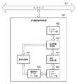
まず本実施形態にかかる画像処理装置の構成を図1を参照しながら説明する。画像処理装置100は、設定情報の送受信機能を備える画像処理装置であり、具体的には、原稿の読み取りや印刷が可能であるネットワーク接続可能なコピー機である。<Configuration of image processing apparatus>
First, the configuration of the image processing apparatus according to the present embodiment will be described with reference to FIG. The
101はリーダ部であり、原稿画像を光学的に読み取り、画像データに変換する。リーダ部101は、原稿を読み取るための機能を持つスキャナユニット103と、原稿用紙を搬送するための機能を持つ原稿給紙ユニット(DFユニット)102とで構成される。 A
プリンタ部110は、記録紙を搬送し、その上に画像データを可視画像として印字して装置外に排紙する。プリンタ部110は、複数種類の記録紙カセットを持つ給紙ユニット109と、画像データを記録紙に転写、定着させる機能を持つマーキングユニット107と、印字された記録紙をソート、ステイプルして装置外へ出力する機能を持つ排紙ユニット108とで構成される。 The
104はコントローラ部であり、リーダ部101、プリンタ部110と電気的に接続され、さらにネットワーク111と接続されている。コントローラ部104は、リーダ部101を制御して原稿の画像データを読み込み、プリンタ部110を制御して画像データを記録用紙に出力するコピー機能を提供する。また、リーダ部101から読み取った画像データを、コードデータに変換し、ネットワーク111を介して図示しないホストコンピュータへ送信するスキャナ機能や、ホストコンピュータからネットワーク111を介して受信したコードデータを画像データに変換し、プリンタ部110に出力するプリンタ機能を提供する。 A
操作部106は、コントローラ部104に接続され、液晶タッチパネルで構成され、画像処理装置に対して指示入力をするためのユーザI/Fを提供する。 The
<コントローラ部の機能>
次に、コントローラ部104の機能を、図2に示すブロック図をもとに説明する。メインコントローラ211は、主にCPU212と、バスコントローラ213、各種I/Fコントローラ回路とから構成される。<Functions of controller unit>
Next, the function of the
CPU212とバスコントローラ213はコントローラ部104全体の動作を制御するものであり、CPU212はROM214からROM I/F215を経由して読み込んだプログラムに基づいて動作する。また、ホストコンピュータから受信したPDL(ページ記述言語)コードデータを解釈し、ラスターイメージデータに展開する動作も、このプログラムに記述されており、ソフトウェアによって処理される。バスコントローラ213は各I/Fから入出力されるデータ転送を制御するものであり、バス競合時の調停やDMAデータ転送の制御を行う。また、コントローラ部104はさらにWebサーバ機能を備えており、画像処理装置内の種々の情報(装置各部のステータスや、通信管理情報、アドレス帳等)をHTML形式で記述し、外部のPCがWebブラウザを用いて参照することが可能である。 The
DRAM216はDRAM I/F217によってメインコントローラ211と接続されており、CPU212が動作するためのワークエリアや、画像データを蓄積するためのエリアとして使用される。 The
Codec218は、DRAM216に蓄積されたラスターイメージデータをMH/MH/MR/MMR/JBIG/JPEG等の方式で圧縮し、また逆に圧縮され蓄積されたコードデータをラスターイメージデータに伸長する。SRAM219はCodec218の一時的なワーク領域として使用される。Codec218はI/F220を介してメインコントローラ211と接続され、DRAM216との間のデータの転送は、バスコントローラ213によって制御されDMA転送される。 The
Graphic Processor235は、画像回転、変倍処理の処理を行うが、本実施形態にかかる画像処理装置100においては、バーコード情報、透かし情報の抽出・解析や生成・埋め込み等の処理が行われる。 The
外部通信I/Fコントローラ221はI/F223によってメインコントローラ211と接続され、コネクタ222によって外部ネットワークと接続される。外部通信I/Fコントローラ221を介して公知のSMTP(Simple Mail Transfer Protocol)を用いた電子メール送信機能によりリーダ部101からの画像データをCodec218で圧縮し、それを添付ファイルとした電子メールを送信したり、Codec218で得たファイルをFTP(File Transfer Protocol)に従って送信することが可能である。また、外部通信I/Fコントローラ221はWebサーバ機能によりHTML化された装置内部の情報を、本装置のURLにHTTPに従ってポート80より接続してきた端末に送信することも可能である。 The external communication I /
汎用高速バス225には、拡張ボードを接続するための拡張コネクタ224とI/O制御部226とが接続される。汎用高速バスとしては、一般的にPCIバスがあげられる。 An
I/O制御部226には、リーダ部101、プリンタ部110の各CPUと制御コマンドを送受信するための調歩同期シリアル通信コントローラ227が2チャンネル装備されており、I/Oバス228によって外部I/F回路(スキャナI/F240、プリンタI/F245)に接続されている。 The I /
パネルI/F232は、LCDコントローラ231に接続され、操作部106上の液晶画面に表示を行うためのI/Fと、ハードキーやタッチパネルキーの入力を行うためのキー入力I/F230とから構成される。 The panel I /
操作部106は液晶表示部と液晶表示部上に張り付けられたタッチパネル入力装置と、複数個のハードキーを有する。タッチパネルまたはハードキーにより入力された信号は前述したパネルI/F232を介してCPU212に伝えられ、液晶表示部はパネルI/F232から送られてきた画像データを表示するものである。液晶表示部には、本画像処理装置100の操作における機能表示や画像データ等を表示する。 The
リアルタイムクロックモジュール233は、機器内で管理する日付と時刻を更新/保存するためのもので、バックアップ用電池234によってバックアップされている。 The real-
E−IDEコネクタ261は、外部記憶装置を接続するためのものである。本実施形態においては、このI/Fを介してハードディスクドライブ105を接続し、ハードディスク262へ画像データを記憶させたり、ハードディスク262から画像データを読み込む動作を行う。 The
コネクタ242と247は、それぞれリーダ部101とプリンタ部110とに接続され、同調歩同期シリアルI/F(243、248)とビデオI/F(244、249)とから構成される。 The
スキャナI/F240は、コネクタ242を介してリーダ部101と接続され、また、スキャナバス241によってメインコントローラ211と接続されており、リーダ部101から受け取った画像に対して所定の処理を施す機能を有し、さらに、リーダ部101から送られたビデオ制御信号をもとに生成した制御信号を、スキャナバス241に出力する機能も有する。 The scanner I /
スキャナバス241からDRAM216へのデータ転送は、バスコントローラ213によって制御される。 Data transfer from the
プリンタI/F245は、コネクタ247を介してプリンタ部110と接続され、また、プリンタバス246によってメインコントローラ111と接続されており、メインコントローラ211から出力された画像データに所定の処理を施して、プリンタ部110へ出力する機能を有し、さらに、プリンタ部110から送られたビデオ制御信号をもとに生成した制御信号を、プリンタバス246に出力する機能も有する。 The printer I /
DRAM216上に展開されたラスターイメージデータのプリンタ部110への転送は、バスコントローラ213によって制御され、プリンタバス246、ビデオI/F249を経由して、プリンタ部110へDMA転送される。 Transfer of raster image data developed on the
<画像処理システムの構成>
次に、図3を用いて本実施形態にかかる図1に示したような画像処理装置を複数備える画像処理システムについて説明する。図3に示すように、本実施形態にかかる複数の画像処理装置がネットワーク301に接続された画像処理システムにおいて、各画像処理装置は、基準となる設定情報を送信する送信側の画像処理装置として、または、送信された設定情報を受信する受信側の画像処理装置として動作することができる。つまり、各画像処理装置は、送信側の画像処理装置として動作する場合の機能と、受信側の画像処理装置として動作する場合の機能との両方を備えており、いずれの側の画像処理装置として動作するかにより、各機能が切り替えられて使用される。なお、図3の例では、画像処理装置302が送信側の画像処理装置として、画像処理装置303が受信側の画像処理装置としてそれぞれ動作する場合を示している。なお、本実施形態では、設定情報として、外部通信I/Fコントローラ221によって電子メールやFTPで送信を行う際に選択するための複数のアドレス情報(本画像処理装置がFAX機能を有している場合はFAX送信のための電話番号も含む)が登録されたアドレス帳、ユーザ毎にカスタマイズした操作部106への表示情報等を含むものとする。<Configuration of image processing system>
Next, an image processing system including a plurality of image processing apparatuses as shown in FIG. 1 according to the present embodiment will be described with reference to FIG. As shown in FIG. 3, in an image processing system in which a plurality of image processing apparatuses according to this embodiment are connected to a
以下、図4から図8を用いて画像処理システムにおける各画像処理装置の諸機能について説明するが、説明の便宜上、送信側画像処理装置と受信側画像処理装置とにわけて行うものとし、また、各図において同一の機能については同一の参照番号を付している。また、以下において、「CPU212により制御される」とは、DRAM216にロードされたプログラムに基づくCPU212により制御される処理ルーチンを示すものであり、「ハードディスク262内に構成される」とはハードディスク262内の特定のエリアをその機能のために用いることを示すものである。 Hereinafter, various functions of each image processing apparatus in the image processing system will be described with reference to FIGS. 4 to 8. However, for convenience of explanation, the functions are performed separately for the transmission side image processing apparatus and the reception side image processing apparatus. In each figure, the same reference numerals are assigned to the same functions. In the following, “controlled by the
<送受信機能の説明>
図4は、画像処理システムにおける各画像処理装置の送受信機能を説明するための機能ブロック図である。ネットワーク301に接続された画像処理装置のうち、302は送信側画像処理装置を、303は受信側画像処理装置をそれぞれ示している。<Description of transmission / reception function>
FIG. 4 is a functional block diagram for explaining the transmission / reception function of each image processing apparatus in the image processing system. Of the image processing apparatuses connected to the
送信側画像処理装置302は複数の機能から構成される。インターフェース部402(外部通信I/Fコントローラ221に相当)はネットワーク301と送信側画像処理装置302との接続を担当するものである。具体的には、Ethernet(登録商標)との接続に用いるEthernet(登録商標)ボードや、公衆回線との接続に用いるモデム等が利用される。設定情報記憶部405(ハードディスク262内に構成される)に記憶されている設定情報は、設定情報送信部403(CPU212により制御される)により取り出され、データ変換部404(CPU212により制御される)によってXML等のネットワーク301に送信するための形式に変換される。設定情報送信部403は変換されたデータをインターフェース部402を通して受信側画像処理装置303へ送信する。 The transmission-side
受信側画像処理装置303では、インターフェース部407(外部通信I/Fコントローラ221に相当)を通して設定情報受信部408(CPU212により制御される)によって受信されたデータをデータ解釈部409(CPU212により制御される)によって内部形式のデータに変換する。設定情報更新部410(CPU212により制御される)は変換されたデータを設定情報として設定情報記憶部411(ハードディスク262内に構成される)に書き込む。この結果、送信側画像処理装置と受信側画像処理装置の設定情報は同期することになる。なお、この設定情報の送信に際しては、送信可能な全ての設定情報の送信を行う他、項目毎に送信対象の設定情報を選択可能である(アドレス帳のみやユーザ設定のみなど)。 In the reception-side
<設定情報復帰機能の説明>
図5は、画像処理システムにおける受信側画像処理装置の設定情報復帰機能を説明するための機能ブロック図である。303はネットワーク301に接続された受信側画像処理装置を示す。<Description of setting information recovery function>
FIG. 5 is a functional block diagram for explaining the setting information restoration function of the receiving image processing apparatus in the image processing system.
受信側画像処理装置303において、ユーザインターフェース部502(操作部106に相当)はLCDパネルやキーボードから構成され、装置の状態を表示したり、管理者からの入力を受け付ける。送信側画像処理装置(図5において不図示)から設定情報が送られてきた場合、受信側画像処理装置303では、まず、設定情報記憶部411に保存されている設定情報503を、設定情報退避部504(CPU212により制御される)を用いて、設定情報格納部506(ハードディスク262内に構成される)に一旦コピーする。次に、設定情報記憶部411に保存されている設定情報を、送信側画像処理装置から送られた設定情報により更新する。 In the reception-side
ここで、設定情報復帰部505(CPU212により制御される)はユーザインターフェース部502を通して、管理者から更新前の設定情報に戻す旨の指示があると、設定情報格納部506に退避してある設定情報503を読み出し、受信側画像処理装置303の設定情報に上書きする。これにより、更新された設定情報を更新前の設定情報に戻すことができる。 Here, if the setting information return unit 505 (controlled by the CPU 212) is instructed by the administrator to return to the setting information before update through the
<再送信機能の説明>
図6は、画像処理システムにおける送信側画像処理装置の再送信機能を説明するための機能ブロック図である。302は、ネットワーク301に接続された送信側画像処理装置を示す。<Description of retransmission function>
FIG. 6 is a functional block diagram for explaining the retransmission function of the transmission-side image processing apparatus in the image processing system.
送信側画像処理装置302は、設定情報送信部403がインターフェース部402を介して自機の設定情報を他の画像処理装置へ送信した際、履歴記録部603(ハードディスク262内に構成される)が、送信側画像処理装置302内の履歴保存データベース部602(ハードディスク262内に構成される)に送信履歴を保存する。送信履歴には、設定情報送信部403が送信を実行した際の宛先、時刻、送信履歴が記憶されている。管理者は、ユーザインターフェース部605(操作部106に相当)を通して、履歴を確認することが可能であり、管理者の要望があれば、送信再実行部604(CPU212により制御される)を動作させることで履歴情報を元に送信処理を再実行させることができる。 When the setting
<設定情報更新拒否機能の説明>
図7は、画像処理システムにおける受信側画像処理装置の設定情報更新拒否機能を説明するための機能ブロック図である。ネットワーク301に接続された画像処理装置のうち、302は送信側画像処理装置を、303は受信側画像処理装置をそれぞれ示している。<Description of setting information update rejection function>
FIG. 7 is a functional block diagram for explaining the setting information update refusal function of the receiving image processing apparatus in the image processing system. Of the image processing apparatuses connected to the
ネットワーク301を通して、送信側画像処理装置302から送られてきた設定情報は、インターフェース部407を介して設定情報受信部408が受信する。 The setting information transmitted from the transmission side
さらに、受信した設定情報をデータ解釈部409で内部データの形式に変換した後、設定情報更新部410に渡される。ここで、設定情報記憶部411は、変換後のデータを自機の設定情報として更新するが、ユーザインターフェース部502を介して管理者がデータの更新禁止を指示した場合には、更新禁止部707(CPU212により制御される)が設定情報記憶部411へのデータの更新を不可能な状態にする(つまり、ユーザインターフェース部502は更新可否の指示を入力することができる)。なお、更新不可能な状態にするとは、具体的には、記憶するハードディスクを書込み禁止にすることで更新ができない状態にすることをいう。なお、ここでの設定情報更新拒否は、「受信する設定情報の全て」という指示の他、設定項目毎に更新禁止(アドレス帳のみ更新禁止やユーザ設定のみ更新禁止等)の指示が可能である。そして、設定情報更新部410は項目毎に更新可否を判断しながら更新を行う。 Further, the received setting information is converted into an internal data format by the
これにより、設定情報が管理者の意図に反して更新されてしまうといったことを回避することが可能となる。 Thereby, it is possible to avoid that the setting information is updated against the intention of the administrator.
<データ形式変換機能の説明>
図8は、画像処理システムにおける受信側画像処理装置のデータ形式変換機能を説明するための機能ブロック図である。ネットワーク301に接続された画像処理装置のうち、302は送信側画像処理装置を、303は受信側画像処理装置をそれぞれ示している。<Description of data format conversion function>
FIG. 8 is a functional block diagram for explaining the data format conversion function of the receiving image processing apparatus in the image processing system. Of the image processing apparatuses connected to the
ネットワーク301を通して送信側画像処理装置302から送られた設定情報は、インターフェース部407を介して設定情報受信部408にて受信される。 Setting information transmitted from the transmission-side
さらに、受け取った設定情報はデータ解釈部409で内部データの形式に変換された後、設定情報更新部410に渡されるが、その前に、設定情報更新判定部807によって、送信された設定情報の項目が、自機の画像処理装置内に存在するかどうかが判定される。たとえば、送信側画像処理装置302がカラーコピー機であって、受信側画像処理装置303が白黒コピー機の場合、受信側画像処理装置303ではカラー情報に関しての項目が存在しない。しかし、コピー部数や給紙方法など型式によらず共通に使える項目も多い。そこで、設定値更新判定部807が更新可能であると判定した項目が設定情報更新部410に渡され、設定情報記憶部411に保存される。 Further, the received setting information is converted into the internal data format by the
一方、型式が異なる場合には設定情報の意味が同じであるように値を変換して書き込む。たとえば、送信側画像処理装置が白黒コピー機で受信側画像処理装置がカラーコピー機であった場合に、濃度の設定情報を受信した場合を考える。白黒コピー機には、濃度は黒の一種類しか存在せず、カラーコピー機にはCMYK四種類の濃度が存在する。この場合、黒の濃度をCMYKそれぞれに設定するのが妥当と考えられるので、受信側画像処理装置ではCMYKに黒の濃度を書き込まれるよう、データ形式を変換する。 On the other hand, if the model is different, the value is converted and written so that the meaning of the setting information is the same. For example, consider a case where density setting information is received when the transmission-side image processing apparatus is a black-and-white copier and the reception-side image processing apparatus is a color copier. A black-and-white copier has only one density, and a color copier has four CMYK densities. In this case, since it is considered appropriate to set the black density for each of CMYK, the receiving side image processing apparatus converts the data format so that the black density is written in CMYK.
<設定情報送信処理の流れ>
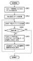
図9は本実施形態にかかる画像処理装置における設定情報送信処理の流れを示すフローチャートである。まず、ステップS901では、送信側画像処理装置内のハードディスクや不揮発性メモリに保存されている設定情報を読み出す。ステップS902では、読み出された設定情報をSOAP形式のデータとして送信するため、XML形式に変換する。<Flow of setting information transmission processing>
FIG. 9 is a flowchart showing a flow of setting information transmission processing in the image processing apparatus according to the present embodiment. First, in step S901, setting information stored in a hard disk or a non-volatile memory in the transmission side image processing apparatus is read. In step S902, the read setting information is converted into XML format in order to be transmitted as SOAP format data.
さらに、ステップS903では、管理者があらかじめ指定した宛先の画像処理装置のインターネットアドレスリストを参照し、リストから一件アドレスを取り出す。ステップS904では、リストのアドレスすべてを処理したかどうかを判定し、全て処理済みであれば一連の処理を終了する。 In step S903, the Internet address list of the destination image processing apparatus designated in advance by the administrator is referred to, and one address is extracted from the list. In step S904, it is determined whether all the addresses in the list have been processed. If all the addresses have been processed, the series of processing ends.
一方、リストのアドレスすべてを処理していないと判定された場合には、ステップS905に進み、前述のXMLに変換したデータを取り出し、SOAPメッセージでくるんだものをHTTPプロトコルで受信側画像処理装置に送信する。受信側画像処理装置は、データ受信後にSOAPのレスポンスとして通信結果を返答する。もし、送信宛先が不正であって、データが受信側画像処理装置に届かない場合は、タイムアウトが発生する。これにより、送信側画像処理装置では、送信失敗であったことが認識できる。 On the other hand, if it is determined that all addresses in the list have not been processed, the process proceeds to step S905, where the data converted into XML is extracted, and the data wrapped in the SOAP message is sent to the receiving image processing apparatus using the HTTP protocol. Send. The receiving side image processing apparatus returns a communication result as a SOAP response after receiving the data. If the transmission destination is invalid and the data does not reach the receiving image processing apparatus, a timeout occurs. As a result, the transmission-side image processing apparatus can recognize that the transmission has failed.
ステップS906では、一件の送信が終了した後に、送信結果とともに宛先や時刻を履歴としてハードディスク内の履歴保存データベース部602に保存する。データの送信は一般に定期的に自動で行われることが多く、管理者は都合の良いときに履歴を参照し、通信に障害が出ていないかを確認することが可能である。宛先などの送信条件はあっているが、何らかの障害で通信が失敗に終わってしまった場合、管理者は履歴リストから失敗した通信の行を選択し、再送信ボタンを押すだけで簡単に送信の再実行が可能である。 In step S906, after one transmission is completed, the destination and time are stored as a history together with the transmission result in the history
ステップS906における処理が終了したら、次の宛先への送信を行うためステップS903へ戻り、ステップS903からS906までの処理を繰り返す。 When the process in step S906 ends, the process returns to step S903 to perform transmission to the next destination, and the processes from step S903 to S906 are repeated.
<設定情報受信処理の流れ>
図10は、本実施形態にかかる受信側画像処理装置における設定情報受信処理の流れを示すフローチャートである。<Flow of setting information reception processing>
FIG. 10 is a flowchart showing a flow of setting information reception processing in the reception-side image processing apparatus according to the present embodiment.
受信側画像処理装置はWebサービスとしてSOAPメッセージを受け付けるようになっている。もし、受信側画像処理装置を送信側画像処理装置として使用したい場合には、SOAPメッセージを受け付けて設定情報が更新されてしまわないよう設定情報の更新禁止状態にしておく。 The receiving image processing apparatus accepts a SOAP message as a Web service. If it is desired to use the reception-side image processing apparatus as the transmission-side image processing apparatus, the setting information is prohibited from being updated so that the SOAP message is accepted and the setting information is not updated.
まず、ステップS1001では、ネットワーク301を通して送信側画像処理装置で作られたSOAPメッセージを受信する。ステップS1002では、受信したSOAPメッセージを、受信側画像処理装置内のハードディスクにファイルとして保存する。 First, in step S1001, a SOAP message generated by the transmission side image processing apparatus is received through the
ステップS1003では、設定情報を更新後に、管理者の希望によって更新前の状態に戻すロールバック動作を実現するために、現在の設定情報をバックアップファイルとして、ハードディスク内に格納する。バックアップをいくつまで格納するかは、ハードディスクの上限を超えないことを条件として、管理者が任意に設定可能である。 In step S1003, after the setting information is updated, the current setting information is stored in the hard disk as a backup file in order to realize a rollback operation for returning to the pre-update state as desired by the administrator. The number of backups to be stored can be arbitrarily set by the administrator on condition that the upper limit of the hard disk is not exceeded.
続いて、ステップS1004では、受信データの型や値の範囲を定義してあるXMLスキーマを参照しながら解析する。なお、スキーマは受信側画像処理装置内に保管されている。ステップS1005では、全ての受信データについて解析を終了したか否かを判定し、解析を終了していれば処理を終了する。 Subsequently, in step S1004, analysis is performed with reference to an XML schema that defines the type and value range of received data. The schema is stored in the receiving image processing apparatus. In step S1005, it is determined whether or not the analysis has been completed for all received data. If the analysis has been completed, the process ends.
一方、全ての受信データについて解析を終了していないと判定された場合には、ステップS1006に進む。ステップS1006では、まず、受信データの項目に存在するが、スキーマ中には該当項目が存在しない場合には、その項目は読み飛ばす。送信側画像処理装置と受信側画像処理装置とで型式が異なる場合や、バージョンが異なっているとこのような状態が発生する。なお、管理者が選択することで、当該読み飛ばした項目の受信データを履歴に残すことも可能である。 On the other hand, if it is determined that the analysis has not been completed for all received data, the process proceeds to step S1006. In step S1006, first, the item exists in the received data item, but if the item does not exist in the schema, the item is skipped. Such a state occurs when the transmission-side image processing device and the reception-side image processing device have different models or different versions. In addition, it is also possible to leave the received data of the skipped item in the history by the administrator selecting.
次に、ステップS1007において受信データの値を検証し、値の範囲が妥当であるかを判定する。値が範囲外の場合にはその項目は読み飛ばす。ステップS1006と同様、送信側画像処理装置と受信側画像処理装置とで型式が異なる場合や、バージョンが異なっているとこのような状態が発生する。なお、管理者が選択することで、当該読み飛ばした項目の受信データを履歴に残すことも可能である。 Next, in step S1007, the value of the received data is verified to determine whether the value range is valid. If the value is out of range, the item is skipped. Similar to step S1006, such a situation occurs when the transmission-side image processing apparatus and the reception-side image processing apparatus have different models or different versions. In addition, it is also possible to leave the received data of the skipped item in the history by the administrator selecting.
ステップS1008では、ステップS1006、S1007を通過した値を設定情報として、受信側画像処理装置内のハードディスクや不揮発性メモリに書き込む。この際、送信側画像処理装置と受信側画像処理装置とで型式が同じであれば値をそのまま書き込むが、型式が異なる場合には設定情報の意味が同じであるように値を変換して書き込む。たとえば、送信側画像処理装置が白黒コピー機で受信側画像処理装置がカラーコピー機であった場合に、濃度の設定情報を受信した場合を考える。白黒コピー機には、濃度は黒の一種類しか存在しないが、カラーコピー機にはCMYK四種類の濃度が存在する。この場合、黒の濃度をCMYKそれぞれに設定するのが妥当と考えられるので、受信側画像処理装置ではCMYKに黒の濃度が書き込まれるようデータ形式を変換する。書き込みが終わったら、次の項目の処理を続けるためにステップS1004へ戻る。 In step S1008, the values that have passed through steps S1006 and S1007 are written as setting information in the hard disk or nonvolatile memory in the receiving image processing apparatus. At this time, if the model is the same between the transmission side image processing apparatus and the reception side image processing apparatus, the value is written as it is, but if the model is different, the value is converted and written so that the meaning of the setting information is the same. . For example, consider a case where density setting information is received when the transmission-side image processing apparatus is a black-and-white copier and the reception-side image processing apparatus is a color copier. A black-and-white copier has only one density, but a color copier has four CMYK densities. In this case, since it is considered appropriate to set the black density for each of CMYK, the receiving image processing apparatus converts the data format so that the black density is written in CMYK. When the writing is finished, the process returns to step S1004 to continue the processing of the next item.
以上のように、本実施形態のように設定情報をXML形式のデータに変換してからやり取りすることにより、汎用性を高めるとともに、将来画像処理装置に種々の機能が追加されたとしてもそれに関する設定情報をもやり取り可能とするように新規のタグの追加によって容易に対応できる。 As described above, the setting information is converted into XML format data and exchanged as in the present embodiment, so that versatility is enhanced and various functions are added to the future image processing apparatus. It can be easily handled by adding a new tag so that setting information can also be exchanged.
また、通信手順としてはSOAPを用いるので、汎用性があり、種々の機器で容易に対応させることが可能となる。また、下位のプロトコルとしてHTTPを用いるので余分なポートをオープンにする必要がなく各装置での対応も容易である。即ち、Webサーバ機能により装置内部の情報を提供する際に用いるポート80を用いるので、通信管理等も容易である。 Further, since SOAP is used as a communication procedure, it is versatile and can be easily handled by various devices. In addition, since HTTP is used as a lower protocol, it is not necessary to open an extra port and it is easy to cope with each device. That is, since the port 80 used when providing information inside the apparatus by the Web server function is used, communication management and the like are easy.
また、本実施形態では、設定情報の同期化のために特別なサーバを設ける必要がないので、システムを安価に構築することが可能となる。 Further, in the present embodiment, it is not necessary to provide a special server for synchronization of setting information, so that the system can be constructed at a low cost.
<他の実施の形態>
なお、本発明は、複数の機器(例えばホストコンピュータ、インタフェイス機器、リーダ、プリンタなど)から構成されるシステムに適用しても、一つの機器からなる装置(例えば、複写機、ファクシミリ装置など)に適用してもよい。<Other embodiments>
Note that the present invention can be applied to a system including a plurality of devices (for example, a host computer, an interface device, a reader, and a printer), and a device (for example, a copying machine and a facsimile device) including a single device. You may apply to.
また、本発明の目的は、前述した実施形態の機能を実現するソフトウェアのプログラムコードを記録した記憶媒体を、システムあるいは装置に供給し、そのシステムあるいは装置のコンピュータ(またはCPUやMPU)が記憶媒体に格納されたプログラムコードを読出し実行することによっても、達成されることは言うまでもない。 Another object of the present invention is to supply a storage medium storing software program codes for implementing the functions of the above-described embodiments to a system or apparatus, and the computer (or CPU or MPU) of the system or apparatus stores the storage medium. Needless to say, this can also be achieved by reading and executing the program code stored in the.
この場合、記憶媒体から読出されたプログラムコード自体が前述した実施形態の機能を実現することになり、そのプログラムコードを記憶した記憶媒体は本発明を構成することになる。 In this case, the program code itself read from the storage medium realizes the functions of the above-described embodiments, and the storage medium storing the program code constitutes the present invention.
プログラムコードを供給するための記憶媒体としては、例えば、フロッピ(登録商標)ディスク、ハードディスク、光ディスク、光磁気ディスク、CD−ROM、CD−R、磁気テープ、不揮発性のメモリカード、ROMなどを用いることができる。 As a storage medium for supplying the program code, for example, a floppy (registered trademark) disk, hard disk, optical disk, magneto-optical disk, CD-ROM, CD-R, magnetic tape, nonvolatile memory card, ROM, or the like is used. be able to.
また、コンピュータが読出したプログラムコードを実行することにより、前述した実施形態の機能が実現されるだけでなく、そのプログラムコードの指示に基づき、コンピュータ上で稼働しているOS(オペレーティングシステム)などが実際の処理の一部または全部を行い、その処理によって前述した実施形態の機能が実現される場合も含まれることは言うまでもない。 Further, by executing the program code read by the computer, not only the functions of the above-described embodiments are realized, but also an OS (operating system) operating on the computer based on the instruction of the program code. It goes without saying that a case where the function of the above-described embodiment is realized by performing part or all of the actual processing and the processing is included.
さらに、記憶媒体から読出されたプログラムコードが、コンピュータに挿入された機能拡張ボードやコンピュータに接続された機能拡張ユニットに備わるメモリに書込まれた後、そのプログラムコードの指示に基づき、その機能拡張ボードや機能拡張ユニットに備わるCPUなどが実際の処理の一部または全部を行い、その処理によって前述した実施形態の機能が実現される場合も含まれることは言うまでもない。 Further, after the program code read from the storage medium is written into a memory provided in a function expansion board inserted into the computer or a function expansion unit connected to the computer, the function expansion is performed based on the instruction of the program code. It goes without saying that the CPU or the like provided in the board or the function expansion unit performs part or all of the actual processing, and the functions of the above-described embodiments are realized by the processing.
Claims (18)
Translated fromJapanese前記画像処理装置を動作させるための設定情報を保持する保持手段と、
前記保持手段に保持された設定情報を前記ネットワークに接続された他の画像処理装置に送信する送信手段と、
前記他の画像処理装置において保持された設定情報であって、当該他の画像処理装置を動作させるための設定情報を、前記ネットワークを介して当該他の画像処理装置から受信する受信手段と、
ユーザより、前記保持手段に保持された設定情報についての更新可否の指示を受け付ける可否指示受付手段と、
前記可否指示受付手段により、更新不可の指示を受け付けた場合は、前記保持手段に保持された設定情報を更新せず、前記可否指示受付手段により、更新可能である旨の指示を受け付けた場合は、前記受信手段によって受信された設定情報を用いて、前記保持手段に保持された設定情報を更新する更新手段と、
前記受信手段が前記他の画像処理装置を動作させるための設定情報を受信した場合に、前記更新手段によって更新される前に前記保持手段が保持していた設定情報を、予め定められた格納手段に退避する退避手段と、
ユーザより、前記更新手段によって更新された設定情報を、更新前の設定情報に戻す旨の指示を受け付ける復帰指示受付手段と、
前記復帰指示受付手段が更新前の設定情報に戻す旨の指示を受け付けた場合に、前記更新手段によって更新された設定情報を、前記退避手段によって退避された設定情報に戻す復帰手段と
を備えることを特徴とする画像処理装置。An image processing apparatus connectable to a network,
Holding means for holding setting information for operating the image processing apparatus;
Transmitting means for transmitting the setting information held in the holding means to another image processing apparatus connected to the network;
Receiving means for receiving setting information stored in the other image processing apparatus for operating the other image processing apparatus from the other image processing apparatus via the network;
From a user, a permission instruction accepting means for accepting an instruction of whether or not to update the setting information held in the holding means;
When an instruction indicating that updating is not possible is received by the availability instruction accepting unit, the setting information held in the holding unit is not updated, and when an instruction indicating that updating is possible is received by the availability instruction accepting unit Updating means for updating the setting information held in the holding means usingthe setting informationreceived by the receiving means;
When the receiving means receives the setting information for operating the other image processing apparatus, the setting information held by the holding means before being updated by the updating means is stored in a predetermined storage means. Evacuation means for evacuating to,
From the user, the setting information updated by said updatingmeans, a return instruction accepting means for accepting an instruction to return to the pre-update setting information,
When the return instruction receiving unit receives an instruction to return to the setting information before updating,the configuration information updated by the updating means, be provided with a return meansfor returning the settinginformation saved by said saving means An image processing apparatus.
前記保持手段に保持された設定情報と、前記他の画像処理装置を動作させるための設定情報とを対比し、共通する設定項目について更新を行うことを特徴とする請求項1乃至3のいずれか1項に記載の画像処理装置。The updating means includes
Asetting information held in the holding means, and comparing the setting information for operating the other image processing apparatus, any one of claims 1 to3, characterized in that updating the setting items in common The image processing apparatus according toitem 1 .
前記画像処理装置を動作させるための設定情報を保持手段に保持する保持工程と、
前記保持手段に保持された設定情報を前記ネットワークに接続された他の画像処理装置に送信する送信工程と、
前記他の画像処理装置において保持された設定情報であって、当該他の画像処理装置を動作させるための設定情報を、前記ネットワークを介して当該他の画像処理装置から受信する受信工程と、
ユーザより、前記保持手段に保持された設定情報についての更新可否の指示を受け付ける可否指示受付工程と、
前記可否指示受付工程において更新不可の指示を受け付けた場合は、前記保持手段に保持された設定情報を更新せず、前記可否指示受付工程において更新可能である旨の指示を受け付けた場合は、前記受信工程において受信された設定情報を用いて、前記保持手段に保持された設定情報を更新する更新工程と、
前記受信工程において前記他の画像処理装置を動作させるための設定情報を受信した場合に、前記更新工程において更新される前に前記保持手段が保持していた設定情報を、予め定められた格納手段に退避する退避工程と、
ユーザより、前記更新工程において更新された設定情報を、更新前の設定情報に戻す旨の指示を受け付ける復帰指示受付工程と、
前記復帰指示受付工程において更新前の設定情報に戻す旨の指示を受け付けた場合に、前記更新工程において更新された設定情報を、前記退避工程において退避された設定情報に戻す復帰工程と
を備えることを特徴とする情報処理方法。An information processing method in an image processing apparatus connectable to a network,
A holding step forholding setting information for operating the image processing apparatus in aholding unit ;
A transmission step of transmitting the setting information held in the holding means to another image processing apparatus connected to the network;
A receiving step for receiving setting information held in the other image processing apparatus, the setting information for operating the other image processing apparatus from the other image processing apparatus via the network;
From a user, a permission / inhibition instruction receiving step of receiving an update permission / inhibition instruction for the setting information held in the holding unit;
If an instruction that cannot be updated is received in the availability instruction accepting step, the setting information held in the holding unit is not updated, and if an instruction that the update is possible is accepted in the availability instruction accepting step, An update step for updating the setting information held in the holding means using the setting information received in the receiving step;
When setting information for operating the other image processing apparatus is received in the receiving step, the setting information held by the holding unit before being updated in the updating step is stored in a predetermined storage unit. An evacuation process to evacuate to,
From the user, the setting informationOite updated on the updatingstep, a return instruction accepting step of accepting an instruction to return to the pre-update configuration information,
When accepting an instruction to return to the setting information before update in the return instruction accepting step,the setting information updated in the update step, and a return stepof returning the settinginformation saved in the save step An information processing method characterized by the above.
前記複数の画像処理装置は、それぞれ、
前記画像処理装置を動作させるための設定情報を保持する保持手段と、
前記保持手段に保持された設定情報を前記ネットワークに接続された他の画像処理装置に送信する送信手段と、
前記他の画像処理装置において保持された設定情報であって、当該他の画像処理装置を動作させるための設定情報を、前記ネットワークを介して当該他の画像処理装置から受信する受信手段と、
ユーザより、前記保持手段に保持された設定情報についての更新可否の指示を受け付ける可否指示受付手段と、
前記可否指示受付手段により、更新不可の指示を受け付けた場合は、前記保持手段に保持された設定情報を更新せず、前記可否指示受付手段により、更新可能である旨の指示を受け付けた場合は、前記受信手段によって受信された設定情報を用いて、前記保持手段に保持された設定情報を更新する更新手段と、
前記受信手段が前記他の画像処理装置を動作させるための設定情報を受信した場合に、前記更新手段によって更新される前に前記保持手段が保持していた設定情報を、予め定められた格納手段に退避する退避手段と、
ユーザより、前記更新手段によって更新された設定情報を、更新前の設定情報に戻す旨の指示を受け付ける復帰指示受付手段と、
前記復帰指示受付手段が更新前の設定情報に戻す旨の指示を受け付けた場合に、前記更新手段によって更新された設定情報を、前記退避手段によって退避された設定情報に戻す復帰手段と
を備えることを特徴とするネットワークシステム。A network system in which aplurality of image processing apparatuses are connected ,
Each of the plurality of image processing devices is
Holding means for holding setting information for operating the image processing apparatus;
Transmitting meansfor transmittingthe setting information held in the holding means to another image processing apparatus connected to the network ;
Receiving means for receiving setting information stored in the other image processing apparatus for operating the other image processing apparatus from the other image processing apparatus via the network;
From a user, a permission instruction accepting means for accepting an instruction of whether or not to update the setting information held in the holding means;
When an instruction indicating that updating is not possible is received by the availability instruction accepting unit, the setting information held in the holding unit is not updated, and when an instruction indicating that updating is possible is received by the availability instruction accepting unit Updating meansfor updatingthe setting information held in the holding means using the setting information received by the receiving means;
When the receiving means receives the setting information for operating the other image processing apparatus, the setting information held by the holding means before being updated by the updating means is stored in a predetermined storage means. Evacuation means for evacuating to,
From the user, the setting information updated by said updatingmeans, a return instruction accepting means for accepting an instruction to return to the pre-update setting information,
When the return instruction receiving unit receives an instruction to return to the setting information before updating,the configuration information updated by the updating means, be provided with a return meansfor returning the settinginformation saved by said saving means A network system characterized by
前記送信手段は、前記送信履歴に含まれる送信宛先を用いて再送信可能であることを特徴とする請求項9乃至11のいずれか1項に記載のネットワークシステム。A recording unit that records a transmission history when the setting information is transmitted by the transmission unit;
The transmission unit, the network system according to anyone ofclaims9 to11, wherein the possible re-transmitted using the transmission destination included in the transmission history.
前記画像処理装置を動作させるための設定情報を保持手段に保持する保持工程と、
前記保持手段に保持された設定情報を前記ネットワークに接続された他の画像処理装置に送信する送信工程と、
前記他の画像処理装置において保持された設定情報であって、当該他の画像処理装置を動作させるための設定情報を、前記ネットワークを介して当該他の画像処理装置から受信する受信工程と、
ユーザより、前記保持手段に保持された設定情報についての更新可否の指示を受け付ける可否指示受付工程と、
前記可否指示受付工程において更新不可の指示を受け付けた場合は、前記保持手段に保持された設定情報を更新せず、前記可否指示受付工程において更新可能である旨の指示を受け付けた場合は、前記受信工程において受信された設定情報を用いて、前記保持手段に保持された設定情報を更新する更新工程と、
前記受信工程において前記他の画像処理装置を動作させるための設定情報を受信した場合に、前記更新工程において更新される前に前記保持手段が保持していた設定情報を、予め定められた格納手段に退避する退避工程と、
ユーザより、前記更新工程において更新された設定情報を、更新前の設定情報に戻す旨の指示を受け付ける復帰指示受付工程と、
前記復帰指示受付工程において更新前の設定情報に戻す旨の指示を受け付けた場合に、前記更新工程において更新された設定情報を、前記退避工程において退避された設定情報に戻す復帰工程と
を備えることを特徴とする情報処理方法。An information processing method ina network system inwhich a plurality of image processing apparatuses are connected ,
A holding step for holding setting information for operating the image processing apparatus in a holding unit;
A transmission stepof transmittingthe setting information held in the holding means to another image processing apparatus connected to the network ;
A receiving step for receiving setting information held in the other image processing apparatus, the setting information for operating the other image processing apparatus from the other image processing apparatus via the network;
From a user, a permission / inhibition instruction receiving step of receiving an update permission / inhibition instruction for the setting information held in the holding unit;
If an instruction that cannot be updated is received in the availability instruction accepting step, the setting information held in the holding unit is not updated, and if an instruction that the update is possible is accepted in the availability instruction accepting step, An update step for updatingthe setting informationheld in the holding means using the setting information received in the receiving step ;
When setting information for operating the other image processing apparatus is received in the receiving step, the setting information held by the holding unit before being updated in the updating step is stored in a predetermined storage unit. An evacuation process to evacuate to,
From the user, the setting informationOite updated on the updating step, a return instruction accepting step of accepting an instruction to return to the pre-update configuration information,
When accepting an instruction to return to the setting information before update in the return instruction accepting step,the setting information updated in the update step, and a return stepof returning the settinginformation saved in the save step An information processing method characterized by the above.
Priority Applications (4)
| Application Number | Priority Date | Filing Date | Title |
|---|---|---|---|
| JP2004220685AJP4208786B2 (en) | 2004-07-28 | 2004-07-28 | Image processing apparatus, network system, information processing method, program, and storage medium |
| US11/189,773US20060023254A1 (en) | 2004-07-28 | 2005-07-27 | Image processing apparatus, network system, information processing method, program, and storage medium |
| US13/401,823US8477356B2 (en) | 2004-07-28 | 2012-02-21 | User selected setting update between image processing apparatuses on a network |
| US13/925,503US9152365B2 (en) | 2004-07-28 | 2013-06-24 | Image processing apparatus, network system, information processing method, program, and storage medium |
Applications Claiming Priority (1)
| Application Number | Priority Date | Filing Date | Title |
|---|---|---|---|
| JP2004220685AJP4208786B2 (en) | 2004-07-28 | 2004-07-28 | Image processing apparatus, network system, information processing method, program, and storage medium |
Publications (2)
| Publication Number | Publication Date |
|---|---|
| JP2006040061A JP2006040061A (en) | 2006-02-09 |
| JP4208786B2true JP4208786B2 (en) | 2009-01-14 |
Family
ID=35731799
Family Applications (1)
| Application Number | Title | Priority Date | Filing Date |
|---|---|---|---|
| JP2004220685AExpired - Fee RelatedJP4208786B2 (en) | 2004-07-28 | 2004-07-28 | Image processing apparatus, network system, information processing method, program, and storage medium |
Country Status (2)
| Country | Link |
|---|---|
| US (3) | US20060023254A1 (en) |
| JP (1) | JP4208786B2 (en) |
Cited By (1)
| Publication number | Priority date | Publication date | Assignee | Title |
|---|---|---|---|---|
| CN107087081A (en)* | 2011-12-26 | 2017-08-22 | 富士施乐株式会社 | Information processing device and information processing method |
Families Citing this family (13)
| Publication number | Priority date | Publication date | Assignee | Title |
|---|---|---|---|---|
| US8179545B2 (en)* | 2006-02-08 | 2012-05-15 | Ricoh Company, Ltd. | Adaptive configuration of imaging devices |
| JP4293195B2 (en) | 2006-03-10 | 2009-07-08 | コニカミノルタビジネステクノロジーズ株式会社 | Information processing system, information processing apparatus, and terminal registration method |
| JP4618804B2 (en)* | 2006-03-24 | 2011-01-26 | キヤノン株式会社 | Information processing apparatus, information processing method, and computer program |
| JP2008210371A (en)* | 2007-02-01 | 2008-09-11 | Sharp Corp | Information processing system |
| JP4849631B2 (en)* | 2007-05-24 | 2012-01-11 | 株式会社リコー | Image forming apparatus, control method, and program |
| JP4849629B2 (en)* | 2007-05-10 | 2012-01-11 | 株式会社リコー | Image forming apparatus, image forming apparatus control method, and program |
| JP5222642B2 (en)* | 2008-07-11 | 2013-06-26 | 京セラドキュメントソリューションズ株式会社 | Image forming apparatus |
| JP4666400B2 (en) | 2008-01-11 | 2011-04-06 | シャープ株式会社 | Multifunction machine and synchronization system |
| JP5377235B2 (en) | 2009-01-28 | 2013-12-25 | キヤノン株式会社 | Information distribution apparatus, information distribution method, and computer program |
| JP5560819B2 (en)* | 2010-03-25 | 2014-07-30 | セイコーエプソン株式会社 | Connection system, connection system setting information management method and program |
| JP6192358B2 (en)* | 2013-05-17 | 2017-09-06 | キヤノン株式会社 | Information processing apparatus, information processing method, and program |
| US10540071B2 (en)* | 2015-09-08 | 2020-01-21 | Apple Inc. | Device, method, and graphical user interface for displaying a zoomed-in view of a user interface |
| US10416942B2 (en)* | 2016-09-29 | 2019-09-17 | Ricoh Company, Ltd. | Image processing apparatus, information processing system, information processing method, and recording medium |
Family Cites Families (28)
| Publication number | Priority date | Publication date | Assignee | Title |
|---|---|---|---|---|
| JPH03180378A (en) | 1989-12-08 | 1991-08-06 | Ricoh Co Ltd | printer controller |
| JPH0816368A (en) | 1994-06-29 | 1996-01-19 | Fujitsu Ltd | Setup information processing device |
| JPH08197813A (en) | 1995-01-31 | 1996-08-06 | Tec Corp | Printer |
| JP4006031B2 (en) | 1995-06-05 | 2007-11-14 | キヤノン株式会社 | Printing device |
| JPH09149076A (en)* | 1995-09-22 | 1997-06-06 | Canon Inc | Data communication device and method |
| JPH10309848A (en) | 1997-05-12 | 1998-11-24 | Canon Inc | Printing apparatus, printer control program updating method, and storage medium |
| US7120910B2 (en) | 2000-03-29 | 2006-10-10 | Canon Kabushiki Kaisha | Control method for image processing apparatus connectable to computer network |
| US7139102B2 (en)* | 2000-05-02 | 2006-11-21 | Ricoh Company, Ltd. | Image processing device, image processing method and remote-scan image processing system using the same |
| US6999211B2 (en)* | 2000-07-19 | 2006-02-14 | Canon Kabushiki Kaisha | Original conveying apparatus, light amount adjustment method for light-emitting section thereof, image forming apparatus, control method therefor, storage control device, storage control method, and storage medium |
| US7194526B2 (en)* | 2000-09-22 | 2007-03-20 | Kyocera Corporation | Network device management method, and network devices |
| JP4501271B2 (en) | 2000-11-09 | 2010-07-14 | ブラザー工業株式会社 | Communication apparatus and storage medium |
| US7006249B2 (en)* | 2001-01-18 | 2006-02-28 | Kabushiki Kaisha Toshiba | Image forming system |
| US7218976B2 (en)* | 2001-04-27 | 2007-05-15 | Canon Kabushiki Kaisha | User interface control apparatus and method |
| US7359074B2 (en)* | 2001-08-20 | 2008-04-15 | Ricoh Company, Ltd. | Image forming apparatus associating with other apparatuses through network |
| JP4075340B2 (en) | 2001-08-27 | 2008-04-16 | ブラザー工業株式会社 | Network system, management device, storage medium, and program |
| JP4300738B2 (en)* | 2002-03-04 | 2009-07-22 | ヤマハ株式会社 | Electronics |
| WO2003081443A1 (en)* | 2002-03-25 | 2003-10-02 | Ricoh Company, Ltd. | Image formation device having a web service function |
| JP3831352B2 (en) | 2002-03-25 | 2006-10-11 | 株式会社リコー | Computer-readable program for causing a computer to perform program generation processing |
| JP3622913B2 (en)* | 2002-03-25 | 2005-02-23 | ソニー株式会社 | Information image utilization system, information image management apparatus, information image management method, user information image, program, and recording medium |
| JP4026540B2 (en)* | 2002-05-22 | 2007-12-26 | セイコーエプソン株式会社 | Printer, setting method thereof, program thereof and cartridge |
| JP2004078392A (en)* | 2002-08-13 | 2004-03-11 | Seiko Epson Corp | Automatic configuration of network devices |
| JP2004088182A (en) | 2002-08-23 | 2004-03-18 | Konica Minolta Holdings Inc | Image processing system |
| JP4225869B2 (en) | 2002-09-16 | 2009-02-18 | 株式会社リコー | Authentication control method and scan server apparatus |
| JP4078950B2 (en)* | 2002-10-29 | 2008-04-23 | 富士ゼロックス株式会社 | Information updating system and information updating method of information updating system |
| JP4085930B2 (en)* | 2002-11-08 | 2008-05-14 | コニカミノルタホールディングス株式会社 | Image processing device |
| JP2004172757A (en)* | 2002-11-18 | 2004-06-17 | Konica Minolta Holdings Inc | Image forming apparatus |
| JP4188074B2 (en)* | 2002-12-19 | 2008-11-26 | 株式会社沖データ | Parameter setting computer via network |
| JP4038720B2 (en) | 2002-12-25 | 2008-01-30 | 富士フイルム株式会社 | Image recording device |
- 2004
- 2004-07-28JPJP2004220685Apatent/JP4208786B2/ennot_activeExpired - Fee Related
- 2005
- 2005-07-27USUS11/189,773patent/US20060023254A1/ennot_activeAbandoned
- 2012
- 2012-02-21USUS13/401,823patent/US8477356B2/ennot_activeExpired - Fee Related
- 2013
- 2013-06-24USUS13/925,503patent/US9152365B2/ennot_activeExpired - Lifetime
Cited By (2)
| Publication number | Priority date | Publication date | Assignee | Title |
|---|---|---|---|---|
| CN107087081A (en)* | 2011-12-26 | 2017-08-22 | 富士施乐株式会社 | Information processing device and information processing method |
| CN107087081B (en)* | 2011-12-26 | 2019-12-10 | 富士施乐株式会社 | Information processing apparatus |
Also Published As
| Publication number | Publication date |
|---|---|
| US20060023254A1 (en) | 2006-02-02 |
| US20140002855A1 (en) | 2014-01-02 |
| US9152365B2 (en) | 2015-10-06 |
| US8477356B2 (en) | 2013-07-02 |
| US20120176647A1 (en) | 2012-07-12 |
| JP2006040061A (en) | 2006-02-09 |
Similar Documents
| Publication | Publication Date | Title |
|---|---|---|
| US9152365B2 (en) | Image processing apparatus, network system, information processing method, program, and storage medium | |
| JP4128516B2 (en) | Image forming apparatus and program updating method | |
| KR100940144B1 (en) | Image output device, control method of image output device, electronic document management system | |
| JP4861883B2 (en) | Image forming apparatus and application execution method | |
| US8462370B2 (en) | Image processing apparatus and application executing method | |
| JP2004266471A (en) | Service processing system and program | |
| JP2004274150A (en) | Service processing system and program | |
| JP2003256216A (en) | Software-embedded electronic devices | |
| JP5893294B2 (en) | Image processing apparatus, control method therefor, and program | |
| KR20100048081A (en) | Image forming method for using portable storage medium and image forming device | |
| JP2000032203A (en) | Parameter sharing method and system for image processor | |
| JP4856622B2 (en) | Image forming apparatus and program updating method | |
| JP2001339561A (en) | Composite image processing apparatus and recovery method in network copying | |
| JP2004265175A (en) | Job processing system | |
| JPH11134236A (en) | Image processing apparatus and control method thereof | |
| JP2001339549A (en) | Composite image processing apparatus and network transfer control method | |
| JP4923694B2 (en) | Embedded information processing equipment | |
| JP3873878B2 (en) | Facsimile server device | |
| JP2007300259A (en) | Image processing apparatus, program management method, storage medium, and program | |
| JP2004094563A (en) | Image forming system and image forming method | |
| JP2007336484A (en) | Information device, control method therefor, information processing system, program, and storage medium | |
| JP2006166168A (en) | Image forming system | |
| JP2006195818A (en) | Image processing apparatus and method, and image processing system | |
| JP2005277993A (en) | Image processing apparatus | |
| JP2004088493A (en) | Copying machine |
Legal Events
| Date | Code | Title | Description |
|---|---|---|---|
| A521 | Request for written amendment filed | Free format text:JAPANESE INTERMEDIATE CODE: A523 Effective date:20051101 | |
| A621 | Written request for application examination | Free format text:JAPANESE INTERMEDIATE CODE: A621 Effective date:20051101 | |
| A977 | Report on retrieval | Free format text:JAPANESE INTERMEDIATE CODE: A971007 Effective date:20080523 | |
| A131 | Notification of reasons for refusal | Free format text:JAPANESE INTERMEDIATE CODE: A131 Effective date:20080620 | |
| A521 | Request for written amendment filed | Free format text:JAPANESE INTERMEDIATE CODE: A523 Effective date:20080819 | |
| TRDD | Decision of grant or rejection written | ||
| A01 | Written decision to grant a patent or to grant a registration (utility model) | Free format text:JAPANESE INTERMEDIATE CODE: A01 Effective date:20081003 | |
| A01 | Written decision to grant a patent or to grant a registration (utility model) | Free format text:JAPANESE INTERMEDIATE CODE: A01 | |
| A61 | First payment of annual fees (during grant procedure) | Free format text:JAPANESE INTERMEDIATE CODE: A61 Effective date:20081021 | |
| R150 | Certificate of patent or registration of utility model | Ref document number:4208786 Country of ref document:JP Free format text:JAPANESE INTERMEDIATE CODE: R150 | |
| FPAY | Renewal fee payment (event date is renewal date of database) | Free format text:PAYMENT UNTIL: 20111031 Year of fee payment:3 | |
| FPAY | Renewal fee payment (event date is renewal date of database) | Free format text:PAYMENT UNTIL: 20111031 Year of fee payment:3 | |
| FPAY | Renewal fee payment (event date is renewal date of database) | Free format text:PAYMENT UNTIL: 20121031 Year of fee payment:4 | |
| FPAY | Renewal fee payment (event date is renewal date of database) | Free format text:PAYMENT UNTIL: 20131031 Year of fee payment:5 | |
| LAPS | Cancellation because of no payment of annual fees |