JP4208599B2 - Bearing with rotation sensor - Google Patents
Bearing with rotation sensorDownload PDFInfo
- Publication number
- JP4208599B2 JP4208599B2JP2003039674AJP2003039674AJP4208599B2JP 4208599 B2JP4208599 B2JP 4208599B2JP 2003039674 AJP2003039674 AJP 2003039674AJP 2003039674 AJP2003039674 AJP 2003039674AJP 4208599 B2JP4208599 B2JP 4208599B2
- Authority
- JP
- Japan
- Prior art keywords
- outer ring
- ring
- bearing
- welding
- rotation sensor
- Prior art date
- Legal status (The legal status is an assumption and is not a legal conclusion. Google has not performed a legal analysis and makes no representation as to the accuracy of the status listed.)
- Expired - Lifetime
Links
- 238000003466weldingMethods0.000claimsdescription31
- 239000002184metalSubstances0.000claimsdescription16
- 238000005452bendingMethods0.000claimsdescription9
- 239000000314lubricantSubstances0.000claimsdescription9
- 230000002093peripheral effectEffects0.000claimsdescription8
- 238000010894electron beam technologyMethods0.000claimsdescription6
- 238000000151depositionMethods0.000claims1
- 238000005096rolling processMethods0.000description7
- 230000007935neutral effectEffects0.000description5
- 238000000034methodMethods0.000description4
- 239000010409thin filmSubstances0.000description4
- 230000000694effectsEffects0.000description3
- 239000012530fluidSubstances0.000description3
- 239000004519greaseSubstances0.000description3
- 239000000463materialSubstances0.000description3
- 230000005347demagnetizationEffects0.000description2
- 230000005489elastic deformationEffects0.000description2
- 238000000605extractionMethods0.000description2
- 230000001681protective effectEffects0.000description2
- 238000010008shearingMethods0.000description2
- 229910000760Hardened steelInorganic materials0.000description1
- 239000003795chemical substances by applicationSubstances0.000description1
- 230000006835compressionEffects0.000description1
- 238000007906compressionMethods0.000description1
- 238000005336crackingMethods0.000description1
- JEIPFZHSYJVQDO-UHFFFAOYSA-Niron(III) oxideInorganic materialsO=[Fe]O[Fe]=OJEIPFZHSYJVQDO-UHFFFAOYSA-N0.000description1
- 238000005461lubricationMethods0.000description1
- 230000003449preventive effectEffects0.000description1
- 230000000644propagated effectEffects0.000description1
- 239000011347resinSubstances0.000description1
- 229920005989resinPolymers0.000description1
Images


Classifications
- F—MECHANICAL ENGINEERING; LIGHTING; HEATING; WEAPONS; BLASTING
- F16—ENGINEERING ELEMENTS AND UNITS; GENERAL MEASURES FOR PRODUCING AND MAINTAINING EFFECTIVE FUNCTIONING OF MACHINES OR INSTALLATIONS; THERMAL INSULATION IN GENERAL
- F16C—SHAFTS; FLEXIBLE SHAFTS; ELEMENTS OR CRANKSHAFT MECHANISMS; ROTARY BODIES OTHER THAN GEARING ELEMENTS; BEARINGS
- F16C41/00—Other accessories, e.g. devices integrated in the bearing not relating to the bearing function as such
- F16C41/007—Encoders, e.g. parts with a plurality of alternating magnetic poles
- F—MECHANICAL ENGINEERING; LIGHTING; HEATING; WEAPONS; BLASTING
- F16—ENGINEERING ELEMENTS AND UNITS; GENERAL MEASURES FOR PRODUCING AND MAINTAINING EFFECTIVE FUNCTIONING OF MACHINES OR INSTALLATIONS; THERMAL INSULATION IN GENERAL
- F16C—SHAFTS; FLEXIBLE SHAFTS; ELEMENTS OR CRANKSHAFT MECHANISMS; ROTARY BODIES OTHER THAN GEARING ELEMENTS; BEARINGS
- F16C27/00—Elastic or yielding bearings or bearing supports, for exclusively rotary movement
- F16C27/04—Ball or roller bearings, e.g. with resilient rolling bodies
- F16C27/045—Ball or roller bearings, e.g. with resilient rolling bodies with a fluid film, e.g. squeeze film damping
- F—MECHANICAL ENGINEERING; LIGHTING; HEATING; WEAPONS; BLASTING
- F16—ENGINEERING ELEMENTS AND UNITS; GENERAL MEASURES FOR PRODUCING AND MAINTAINING EFFECTIVE FUNCTIONING OF MACHINES OR INSTALLATIONS; THERMAL INSULATION IN GENERAL
- F16C—SHAFTS; FLEXIBLE SHAFTS; ELEMENTS OR CRANKSHAFT MECHANISMS; ROTARY BODIES OTHER THAN GEARING ELEMENTS; BEARINGS
- F16C19/00—Bearings with rolling contact, for exclusively rotary movement
- F16C19/02—Bearings with rolling contact, for exclusively rotary movement with bearing balls essentially of the same size in one or more circular rows
- F16C19/04—Bearings with rolling contact, for exclusively rotary movement with bearing balls essentially of the same size in one or more circular rows for radial load mainly
- F16C19/06—Bearings with rolling contact, for exclusively rotary movement with bearing balls essentially of the same size in one or more circular rows for radial load mainly with a single row or balls
- F—MECHANICAL ENGINEERING; LIGHTING; HEATING; WEAPONS; BLASTING
- F16—ENGINEERING ELEMENTS AND UNITS; GENERAL MEASURES FOR PRODUCING AND MAINTAINING EFFECTIVE FUNCTIONING OF MACHINES OR INSTALLATIONS; THERMAL INSULATION IN GENERAL
- F16C—SHAFTS; FLEXIBLE SHAFTS; ELEMENTS OR CRANKSHAFT MECHANISMS; ROTARY BODIES OTHER THAN GEARING ELEMENTS; BEARINGS
- F16C2226/00—Joining parts; Fastening; Assembling or mounting parts
- F16C2226/10—Force connections, e.g. clamping
- F—MECHANICAL ENGINEERING; LIGHTING; HEATING; WEAPONS; BLASTING
- F16—ENGINEERING ELEMENTS AND UNITS; GENERAL MEASURES FOR PRODUCING AND MAINTAINING EFFECTIVE FUNCTIONING OF MACHINES OR INSTALLATIONS; THERMAL INSULATION IN GENERAL
- F16C—SHAFTS; FLEXIBLE SHAFTS; ELEMENTS OR CRANKSHAFT MECHANISMS; ROTARY BODIES OTHER THAN GEARING ELEMENTS; BEARINGS
- F16C2226/00—Joining parts; Fastening; Assembling or mounting parts
- F16C2226/30—Material joints
- F16C2226/36—Material joints by welding
- F—MECHANICAL ENGINEERING; LIGHTING; HEATING; WEAPONS; BLASTING
- F16—ENGINEERING ELEMENTS AND UNITS; GENERAL MEASURES FOR PRODUCING AND MAINTAINING EFFECTIVE FUNCTIONING OF MACHINES OR INSTALLATIONS; THERMAL INSULATION IN GENERAL
- F16C—SHAFTS; FLEXIBLE SHAFTS; ELEMENTS OR CRANKSHAFT MECHANISMS; ROTARY BODIES OTHER THAN GEARING ELEMENTS; BEARINGS
- F16C35/00—Rigid support of bearing units; Housings, e.g. caps, covers
- F16C35/04—Rigid support of bearing units; Housings, e.g. caps, covers in the case of ball or roller bearings
- F16C35/06—Mounting or dismounting of ball or roller bearings; Fixing them onto shaft or in housing
- F16C35/067—Fixing them in a housing
Landscapes
- Engineering & Computer Science (AREA)
- General Engineering & Computer Science (AREA)
- Mechanical Engineering (AREA)
- Rolling Contact Bearings (AREA)
- Transmission And Conversion Of Sensor Element Output (AREA)
- Mounting Of Bearings Or Others (AREA)
Description
Translated fromJapanese【0001】
【発明の属する技術分野】
この発明は、回転センサ付き軸受に関し、主として回転センサ付き転がり軸受に関するものである。
【0002】
【従来の技術】
各種回転装置の回転数を検出するために、軸受に磁気エンコーダと磁気センサとからなる回転センサを装着することが従来から知られている。軸受として転がり軸受を使用する場合、一般的には、その軸受を内輪回転型として用い、回転側の内輪に環状の磁気エンコーダを取付けるとともに、固定側の外輪にその磁気エンコーダに所要のすき間をおいて磁気センサが取付けられる(特許文献1又は2参照)。
【0003】
前記の磁気エンコーダを内輪に固定する手段としては、標準軸受に取付ける場合は、幅方向のスペースが極めて狭く、かつ同芯度を確保するために、その芯金を内輪の外径面に圧入することにより固定する手段が採用される。この場合、内輪の内径面に軸が貫通されているので、繰返し荷重が負荷されても、磁気エンコーダが内輪を介して軸によりバックアップされるため、変形のおそれはなく、したがって内輪から磁気エンコーダが外れるおそれがない。
【0004】
なお、特許文献1には、磁気センサ側の金属支持部材(芯金)を固定側である外輪の端面に溶接することが記載されている。
【0005】
一方、軸受一般の技術として、軸受外輪が軸受箱に正のスキマで嵌合されているときに外輪に回転荷重が加わると、いわゆるクリープが発生することが従来から知られている。そのクリープの有効な防止手段として、外輪の外周面と軸受箱との間に2本のリング状環体を介在し、その2本のリング状環体の間の密封空間にグリース等の粘性潤滑剤を付着させる軸受支持構造が知られている(特許文献3参照)。この構造は、軸受の使用時において、外輪に荷重が加わり外輪が軸受箱に対して荷重の方向に偏芯させられた際に、2本のリング状環体間に粘性潤滑剤の高圧流体薄膜を形成させ、その流体薄膜を介して外輪を支持することにより、クリープを防止するようにしたものである。上記の軸受支持構造は、後述のようにこの出願の発明の従来技術となる。
【0006】
【特許文献1】
特開平10−300516号公報(図3、段落0020)
【特許文献2】
特開2002−295465号公報(図1、段落0003)
【特許文献3】
実公昭52−8896号公報(第6図と実施例の説明)
【0007】
【発明が解決しようとする課題】
前記の特許文献1及び2の場合とは逆に、内輪を固定側、外輪を回転側とした外輪回転型の回転センサ付き軸受の場合は、磁気エンコーダは外輪側に取付けられ、磁気センサは内輪側に取付けられる。この場合、従来の取付け手段と同様に、磁気エンコーダを外輪の内径面に圧入固定することにより取付けたとすると、軸受組込み時の打撃、荷重負荷時の外輪に対する繰返し曲げ変形等による抜け出しが発生するおそれがある。また、脱落防止のカシメなど他の固定方法を併用するにはスペースが狭く、併用は不可能である。
【0008】
前記の繰返し曲げ変形が発生する構造は次のようなものである。即ち、回転する外輪の外径面に半径方向内向きの荷重が作用した場合、その荷重が転動体の部分に作用するときの外輪の内方への弾性変形は該転動体に支えられるため小さいが、荷重が転動体相互間に作用した場合は外輪の内方への弾性変形が前者に比べて大きくなる。このような状態で外輪が回転すると外輪に繰返し曲げ変形が発生するのである。このような繰返し曲げ変形の発生により、所要の締めしろをもって圧入した磁気エンコーダが軸方向に抜け出ることがある。ちなみに、内輪回転の場合は、内輪側に軸が嵌っているので、このような現象は生じない。
【0009】
上述のように、外輪回転・外輪回転荷重の条件下で使用される回転センサ付き軸受においては、外輪に取付ける磁気エンコーダを単に外輪に対し圧入固定するだけでは、組込み時や使用時において抜け出すおそれがあることにかんがみ、この発明は、外輪に対し磁気エンコーダを確実に取付け、その抜け出しを防止した外輪回転型の回転センサ付き軸受を提供することを第一の課題とする。
【0010】
一方、外輪回転・外輪回転荷重の条件下で使用される回転センサ付き軸受においては、内輪と軸との間に配線された磁気センサの信号を出力するケーブルの断線を避けるため、両者が相対的に回転する構造は採用できない。このため、軸と内輪はタイトにはめ合わせる必要があるが、クリープ防止の観点からは外輪も軸受箱に対してタイトにはめ合わせる必要がある。しかし、内外輪共にタイトにはめ合わせることは軸受の組込み上困難である。
【0011】
そこで、この発明は、前述の第一の課題と併せ、ケーブルの断線を防止すると共に組付けの容易な構造をもった回転センサ付き軸受を提供することを第二の課題とする。
【0012】
【課題を解決するための手段】
上記の第一の課題を解決するために、この発明は、外輪に芯金を介してエンコーダを取付け、そのエンコーダに対し所要のすき間をおいて対向したセンサを内輪に取付け、前記内輪を固定側、外輪を回転側として使用する外輪回転型の回転センサ付き軸受において、前記エンコーダの芯金を外輪に対して圧入するとともに、その芯金を外輪に対しレーザ溶接又は電子ビーム溶接により固定した構成を採用した。
【0013】
芯金と外輪との溶接方法としては、芯金(例えば、SPCC)と外輪(例えば、SUJ2)が異種材料であること、磁気エンコーダがゴム磁石を用いており熱に弱いこと、外輪が焼き入れされており非常に割れ易い材料であることから、レーザ溶接又は電子ビーム溶接が有効である。
【0014】
また、溶接位置を、外輪の曲げの圧縮応力と引張り応力の中心線上又はその近傍とすることが望ましい。溶接部への負荷を減少させるためである。溶接は芯金の全周又は数点において行う。
【0015】
前記の第二の課題を達成するために、この発明は、前述の回転センサ付き軸受において、その外輪の外周面と軸受箱との間に少なくとも2本のリング状環体を介在し、そのリング状環体の間に粘性潤滑剤を付着させた構成を採用したのである。この構成によると、外輪のクリープが防止されるとともに、外輪と軸受箱のはめ合わせはルーズであるので、軸と内輪とのはめ合わせをタイトにした場合でも外輪側の組込みに支障を来たすことがない。
【0016】
【発明の実施の形態】
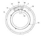
以下、この発明の実施形態を添付図面に基づいて説明する。図1及び図2に示した第1実施例は外輪回転型の転がり軸受であり、外輪1と内輪2の各軌道溝3、4間に保持器5により一定間隔に保持された転動体としてのボール6を介在している。
【0017】
前記外輪1の一方の端面に環状の芯金7に支持された磁気エンコーダ8が取付けられる。磁気エンコーダ8はゴム磁石でなり、周方向に一定間隔で交互に異極に磁化されたものである。芯金7は、小径円筒部7a、円盤部7b、大径円筒部7cからなり、その小径円筒部7aを外輪1の内径面端部に圧入するとともに、円盤部7bを外輪1の端面に当てて取付けられる。大径円筒部7cは、外輪1の曲げ変形の中立線N上にある。円盤部7bと大径円筒部7cとの間の屈曲部は中立線N上にあり、中立線Nにおいて溶接が施される(溶接部9参照)。好ましい溶接法として、レーザ溶接又は電子ビーム溶接を採用することができる。溶接位置は、図2に示すように、数点において点状に溶接した場合を示しているが、全周に施してもよい。
【0018】
前記の芯金7は小径円筒部7a、円盤部7bがあることにより、大径円筒部7cを直接溶接する場合に比べ溶接時の位置決めとなり、高精度に溶接でき、また溶接による変形(倒れ)もない。また、溶接部9の位置を中立線N上に設定することにより、溶接部9における外輪1の曲げは理論上ゼロであり、溶接部9に繰返しせん断力は作用しない。
【0019】
固定側となる内輪2においては、前記の磁気エンコーダ8側の端部外径面に環状のハウジング芯金11が取付けられ、そのハウジング芯金11に樹脂モールドによるセンサハウジング12が一体に設けられる。ハウジング芯金11は大径円筒部11a、円盤部11b及び小径円筒部11cを有し、その大径円筒部11aが内輪2に圧入固定される。また、小径円筒部11c端縁の全周数ヶ所に外径方向への切り起こし13が設けられ、センサハウジング12の抜け止めを図っている。センサハウジング12の外周縁は、その断面形状から分かるように、外輪1の中立線N程度に達しており、また、その外周部内面に全周にわたり軸方向と径方向に切り欠かれたL形の段部14が形成され、その段部14に前記の磁気エンコーダ8が所定のすき間をおいて対向している。
【0020】
前記センサハウジング12の一部分において、周方向に長い凹部15が設けられ、その凹部15内に電気回路基板16に支持された磁気センサ17が収納される。磁気センサ17は前記段部14の軸方向の面から内径面に露出し、磁気エンコーダ8と所定のすき間をおいて径方向に対向する。また、電気回路基板16の部分において、センサハウジング12の内径方向に突き出してケーブル取出し部18が設けられる。このケーブル取出し部18は、内部にケーブル19を挿通した状態で樹脂モールドされる。ケーブル19の一端は電気回路基板16に接続され、また、他端は内輪2の内側に配置された保護チューブ21に挿通され、外部に引出される。
【0021】
なお、前記外輪1と内輪2の他方の端部間に通常のシール部材22が設けられる。
【0022】
図3は前記の第1実施例の実施品、即ち「溶接有り」(但し、溶接はレーザ溶接を採用)と、従来品、即ち「溶接なし」について、負荷荷重と外輪の繰返し変形に対する脱落までの変形回数の試験結果である。「溶接有り」の場合が約100倍の耐久性を発揮することが確認できた。また、レーザ溶接は熱影響が非常に狭いので、溶接前後の変形がなく、磁気エンコーダの脱磁も生じない。また、焼き入れ鋼の軸受材にもクラックを生じない。更に、防錆油の塗布状態での溶接が可能である。なお、電子ビーム溶接の場合も同様の効果が認められた。
【0023】
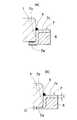
図4(a)(b)は、磁気エンコーダ8の芯金7の他の例を示す。いずれの場合も、外輪1の曲げ変形を小径円筒部7aから円盤部7bを介して溶接部9に伝播させないか又は伝播し難くするようにしたものである。図4(a)の場合は、芯金7の小径円筒部7aを外輪1の内径面にすき間嵌めしている。図4(b)の場合は小径円筒部7aの肉厚t1を他の部分の肉厚tの0.5〜0.8倍の大きさ、即ちt1=0.5〜0.8×tに設定している。
【0024】
次に、図5に示した第2実施例、図6に示した第3実施例は、いずれも軸受の構造は前記第1実施例のものと同一であるが、軸受箱23に対する外輪1の嵌合構造に前掲の特許文献3のクリープ防止構造を採用したものである。即ち、図5の第2実施例の場合は、外輪1の外周面に所要の間隔をおいて2条の周溝24、24を設け、各周溝24、24にリング状環体25、25(例えば、Oリング状ゴム)を装着し、これらのリング状環体25、25を軸受箱23の内周面に押し付ける。2本のリング状環体25、25間にグリース等の粘性潤滑剤26を付着させた密封空間が形成される。
【0025】
図6の第3実施形態の場合は、周溝24、24が軸受箱23の内周面に設けられ、その周溝24、24に装着された同様のリング状環体25、25を外輪1の外周面に押し付けている。2本のリング状環体25、25間にグリース等の粘性潤滑剤26を付着させた密封空間が形成される点は、第2実施例の場合と同様である。
【0026】
上記いずれの実施例の場合も、使用時において外輪1に荷重が加わり軸受箱23に対して荷重の方向に偏芯した際に、2本のリング状環体25、25間に粘性潤滑剤26による高圧流体薄膜が形成され、その流体薄膜を介して外輪1が支持される。リング状環体25、25は粘性潤滑剤26が漏れるのを防ぐとともに、前記薄膜によって浮いている外輪1が軸受の摩擦によって回転方向に回転することが防止されるので、クリープの発生が防止される。
【0027】
また、軸受を組付ける際に、その内輪2に対して軸をタイトにはめ合わせても、外輪1と軸受箱23との嵌合はリング状環体25、25の弾性によりルーズなはめ合いとなるので、軸受の組付け時の支障になることがなく、スムーズに組付けることができる。
【0028】
【発明の効果】
以上のように、この発明によれば、外輪回転型の軸受において、その外輪に取付けた磁気エンコーダの芯金の小径円筒部を外輪内径面に対し圧入するとともに、その芯金の円盤部と大径円筒部のコーナ部を外輪に溶接することにより、該芯金を外輪に固定するようにしたので、磁気エンコーダの外輪からの抜け出しを防止することができる。
【0029】
また、前記の溶接をレーザ溶接又は電子ビーム溶接により行うことにより、熱影響が少ないため、外輪の変形やクラックの発生がなく、また磁気エンコーダの脱磁を防止することができる。防錆油塗布状態での溶接も可能であるので、作業が簡便化できる。
【0030】
さらに、前記芯金の外輪に対する溶接位置を、外輪の曲げの圧縮応力と引張り応力の中心線上又はその近傍に定めることにより、溶接部への繰返しせん断力が作用することを防止することができる。
【0031】
なお、外輪の外周面と軸受箱との間に少なくとも2本のリング状環体を介在し、そのリング状環体の間に粘性潤滑剤を付着させたクリープ防止構造を採用すると、外輪の軸受箱に対する組付けが容易となるので内輪と軸とをタイトにはめ合せることができる。その結果、内輪と軸との相対的回転が防止され、ケーブルの断線を防止することができる。
【図面の簡単な説明】
【図1】実施形態の断面図
【図2】同上の正面図
【図3】同上実験結果のグラフ
【図4】(a)(b)同上の他の例の一部断面図
【図5】第2実施形態の一部拡大断面図
【図6】第3実施形態の一部拡大断面図
【符号の説明】
1 外輪
2 内輪
3 軌道
4 軌道
5 保持器
6 ボール
7 芯金
7a 小径円筒部
7b 円盤部
7c 大径円筒部
8 磁気エンコーダ
9 溶接部
11 ハウジング芯金
12 センサハウジング
13 切り起こし片
14 段部
15 凹部
16 電気回路基板
17 磁気センサ
18 ケーブル取出し部
19 ケーブル
21 保護チューブ
22 シール部材
23 軸受箱
24 周溝
25 リング状環体
26 粘性潤滑剤[0001]
BACKGROUND OF THE INVENTION
The present invention relates to a bearing with a rotation sensor, and mainly relates to a rolling bearing with a rotation sensor.
[0002]
[Prior art]
In order to detect the number of rotations of various rotating devices, it is conventionally known to mount a rotation sensor including a magnetic encoder and a magnetic sensor on a bearing. When a rolling bearing is used as a bearing, generally, the bearing is used as an inner ring rotating type, an annular magnetic encoder is attached to the inner ring on the rotating side, and a required clearance is provided to the magnetic encoder on the outer ring on the fixed side. And a magnetic sensor is attached (see
[0003]
As a means for fixing the magnetic encoder to the inner ring, when it is attached to a standard bearing, the space in the width direction is extremely narrow and the core metal is press-fitted into the outer diameter surface of the inner ring in order to ensure concentricity. Thus, a fixing means is adopted. In this case, since the shaft is passed through the inner diameter surface of the inner ring, even if a repeated load is applied, the magnetic encoder is backed up by the shaft via the inner ring, so there is no possibility of deformation. There is no fear of coming off.
[0004]
[0005]
On the other hand, as a general technique of bearings, it is conventionally known that so-called creep occurs when a rotational load is applied to the outer ring when the bearing outer ring is fitted to the bearing housing with a positive clearance. As an effective means for preventing the creep, two ring-shaped rings are interposed between the outer peripheral surface of the outer ring and the bearing housing, and viscous lubrication such as grease is provided in the sealed space between the two ring-shaped rings. A bearing support structure for adhering an agent is known (see Patent Document 3). In this structure, when a bearing is used, when a load is applied to the outer ring and the outer ring is eccentric with respect to the bearing box in the direction of the load, a high-pressure fluid thin film of a viscous lubricant is provided between the two ring-shaped rings. , And the outer ring is supported through the fluid thin film to prevent creep. The above bearing support structure is the prior art of the invention of this application as will be described later.
[0006]
[Patent Document 1]
Japanese Patent Laid-Open No. 10-300516 (FIG. 3, paragraph 0020)
[Patent Document 2]
JP 2002-295465 A (FIG. 1, paragraph 0003)
[Patent Document 3]
Japanese Utility Model Publication No. 52-8896 (FIG. 6 and explanation of the embodiment)
[0007]
[Problems to be solved by the invention]
Contrary to the cases of
[0008]
The structure in which the repeated bending deformation occurs is as follows. That is, when a radially inward load is applied to the outer diameter surface of the rotating outer ring, the elastic deformation inward of the outer ring when the load is applied to the part of the rolling element is small because it is supported by the rolling element. However, when the load acts between the rolling elements, the elastic deformation inward of the outer ring becomes larger than the former. When the outer ring rotates in such a state, the outer ring is repeatedly bent and deformed. Due to the occurrence of such repeated bending deformation, the magnetic encoder that is press-fitted with a required margin may come off in the axial direction. Incidentally, in the case of inner ring rotation, such a phenomenon does not occur because the shaft is fitted on the inner ring side.
[0009]
As described above, in a bearing with a rotation sensor that is used under the conditions of outer ring rotation and outer ring rotation load, the magnetic encoder attached to the outer ring may be pulled out when assembled or used simply by press-fitting and fixing to the outer ring. In view of this, it is a first object of the present invention to provide an outer ring rotation type bearing with a rotation sensor in which a magnetic encoder is securely attached to an outer ring and the removal thereof is prevented.
[0010]
On the other hand, in bearings with rotation sensors that are used under the conditions of outer ring rotation and outer ring rotation load, the two are relative to avoid disconnection of the cable that outputs the magnetic sensor signal wired between the inner ring and the shaft. A rotating structure cannot be adopted. For this reason, it is necessary to fit the shaft and the inner ring tightly, but it is necessary to fit the outer ring tightly to the bearing housing from the viewpoint of preventing creep. However, it is difficult to fit the inner and outer rings tightly in terms of bearing assembly.
[0011]
Accordingly, a second object of the present invention is to provide a bearing with a rotation sensor that prevents the cable from being disconnected and has a structure that can be easily assembled together with the first problem described above.
[0012]
[Means for Solving the Problems]
In order to solve the above first problem, the present invention attaches an encoder to the outer ring via a cored bar, attaches a sensor facing the encoder with a required clearance to the inner ring, and attaches the inner ring to the fixed side. In the outer ring rotation type bearing with rotation sensor using the outer ring as the rotation side, the encoder core metal is press-fitted into the outer ring, and the core metal is fixed to the outer ring by laser welding or electron beam welding. Adopted.
[0013]
The welding method for the core metal and outer ring is that the core metal (for example, SPCC) and the outer ring (for example, SUJ2) are made of different materials, that the magnetic encoder uses rubber magnets and is susceptible to heat, and the outer ring is quenched. Laser welding or electron beam welding is effective because it is a material that is easily broken.
[0014]
Further, it is desirable that the welding position be on or near the center line of the bending compressive stress and tensile stress of the outer ring. This is to reduce the load on the weld. Welding is performed on the entire circumference or several points of the metal core.
[0015]
In order to achieve the second object, according to the present invention, in the bearing with a rotation sensor described above, at least two ring-shaped rings are interposed between the outer peripheral surface of the outer ring and the bearing housing, and the ring A configuration in which a viscous lubricant is adhered between the ring-shaped rings is adopted. According to this configuration, creep of the outer ring is prevented, and the fitting between the outer ring and the bearing housing is loose. Therefore, even if the fitting between the shaft and the inner ring is tight, it may hinder the assembly on the outer ring side. Absent.
[0016]
DETAILED DESCRIPTION OF THE INVENTION
Embodiments of the present invention will be described below with reference to the accompanying drawings. The first embodiment shown in FIGS. 1 and 2 is a rolling bearing of an outer ring rotating type, and is a rolling element held at a constant interval by a
[0017]
A
[0018]
The cored
[0019]
In the
[0020]
A
[0021]
A
[0022]
FIG. 3 shows the embodiment of the first embodiment, that is, “with welding” (however, laser welding is employed) and the conventional product, that is, “without welding”, until the load is dropped and the outer ring is repeatedly deformed. It is a test result of the number of deformations. It was confirmed that the case of “with welding” exhibited about 100 times durability. Further, since laser welding has a very narrow thermal effect, there is no deformation before and after welding, and no demagnetization of the magnetic encoder occurs. In addition, cracks do not occur in the hardened steel bearing material. Furthermore, it is possible to weld in the state of application of rust preventive oil. Similar effects were observed in the case of electron beam welding.
[0023]
FIGS. 4A and 4B show another example of the cored
[0024]
Next, in the second embodiment shown in FIG. 5 and the third embodiment shown in FIG. 6, the structure of the bearing is the same as that of the first embodiment, but the
[0025]
In the case of the third embodiment in FIG. 6, the
[0026]
In any of the above embodiments, when a load is applied to the
[0027]
Further, even when the shaft is tightly fitted to the
[0028]
【The invention's effect】
As described above, according to the present invention, in the outer ring rotary bearing, the small-diameter cylindrical portion of the core bar of the magnetic encoder attached to the outer ring is press-fitted into the inner surface of the outer ring, and the disk portion of the core bar is large. Since the core metal is fixed to the outer ring by welding the corner portion of the diameter cylindrical portion to the outer ring, the magnetic encoder can be prevented from coming off from the outer ring.
[0029]
Further, by performing the above-described welding by laser welding or electron beam welding, there is little thermal influence, so there is no deformation or cracking of the outer ring, and demagnetization of the magnetic encoder can be prevented. Since welding with a rust-preventing oil applied is also possible, the operation can be simplified.
[0030]
Furthermore, by setting the welding position of the core metal to the outer ring on or near the center line of the bending compression stress and tensile stress of the outer ring, it is possible to prevent the repeated shearing force from acting on the welded portion.
[0031]
If an anti-creep structure in which at least two ring-shaped rings are interposed between the outer peripheral surface of the outer ring and the bearing box and a viscous lubricant is attached between the ring-shaped rings, a bearing for the outer ring is obtained. Since the assembly to the box becomes easy, the inner ring and the shaft can be fitted tightly. As a result, relative rotation between the inner ring and the shaft is prevented, and disconnection of the cable can be prevented.
[Brief description of the drawings]
FIG. 1 is a cross-sectional view of an embodiment. FIG. 2 is a front view of the same. FIG. 3 is a graph of experimental results. FIG. 4 is a partial cross-sectional view of another example. Partially enlarged sectional view of the second embodiment [FIG. 6] Partially enlarged sectional view of the third embodiment [Explanation of symbols]
DESCRIPTION OF
Claims (3)
Translated fromJapanesePriority Applications (1)
| Application Number | Priority Date | Filing Date | Title |
|---|---|---|---|
| JP2003039674AJP4208599B2 (en) | 2003-02-18 | 2003-02-18 | Bearing with rotation sensor |
Applications Claiming Priority (1)
| Application Number | Priority Date | Filing Date | Title |
|---|---|---|---|
| JP2003039674AJP4208599B2 (en) | 2003-02-18 | 2003-02-18 | Bearing with rotation sensor |
Publications (2)
| Publication Number | Publication Date |
|---|---|
| JP2004251316A JP2004251316A (en) | 2004-09-09 |
| JP4208599B2true JP4208599B2 (en) | 2009-01-14 |
Family
ID=33023787
Family Applications (1)
| Application Number | Title | Priority Date | Filing Date |
|---|---|---|---|
| JP2003039674AExpired - LifetimeJP4208599B2 (en) | 2003-02-18 | 2003-02-18 | Bearing with rotation sensor |
Country Status (1)
| Country | Link |
|---|---|
| JP (1) | JP4208599B2 (en) |
Families Citing this family (5)
| Publication number | Priority date | Publication date | Assignee | Title |
|---|---|---|---|---|
| JP2013036596A (en)* | 2011-08-11 | 2013-02-21 | Ntn Corp | Tapered roller bearing and mounting structure therefor |
| US20150330449A1 (en)* | 2014-05-15 | 2015-11-19 | Aktiebolaget Skf | Method for manufacturing a rolling bearing and rolling bearing manufactured according to such a method |
| US11129289B2 (en) | 2015-10-27 | 2021-09-21 | Schaeffler Technologies AG & Co. KG | Bearing assembly with incorporated electric line for providing multiple operating voltages |
| DE102017112028B3 (en)* | 2017-06-01 | 2018-10-11 | Schaeffler Technologies AG & Co. KG | Method for monitoring a bearing, bearing and bearing assembly |
| DE102020107956A1 (en) | 2020-03-23 | 2021-09-23 | Schaeffler Technologies AG & Co. KG | Bearing designed to accommodate a sensor unit |
- 2003
- 2003-02-18JPJP2003039674Apatent/JP4208599B2/ennot_activeExpired - Lifetime
Also Published As
| Publication number | Publication date |
|---|---|
| JP2004251316A (en) | 2004-09-09 |
Similar Documents
| Publication | Publication Date | Title |
|---|---|---|
| JP5334287B2 (en) | Bearing seal | |
| JP5914585B2 (en) | Wheel bearing device | |
| US7926816B2 (en) | Sealing device with tone wheel | |
| JP2008151174A (en) | Sealing device | |
| JP5894389B2 (en) | Wheel bearing device | |
| EP2541088A1 (en) | Ball bearing equipped with encoder for detecting rotational speed of wheel of two-wheeled motor vehicle, and device for detecting rotational speed of wheel of two-wheeled motor vehicle, the device using the ball bearing | |
| JP2007107674A (en) | Sealing device | |
| US6796713B2 (en) | Instrumented antifriction bearing provided with a sealing device | |
| JP4208599B2 (en) | Bearing with rotation sensor | |
| JP6654941B2 (en) | Wheel bearing device | |
| JP2010002009A (en) | Rolling device | |
| JP6012803B2 (en) | Wheel bearing device | |
| JP2001153145A (en) | Sealed rolling bearing | |
| JP2012224265A (en) | Bearing device for wheel | |
| JP2008157327A (en) | Bearing device for wheel | |
| JP7493223B2 (en) | Sealing device | |
| JP2008075832A (en) | Rolling bearing device | |
| JP2009024804A (en) | Sealing device | |
| JP2003278777A (en) | Rolling bearing device | |
| JP2005325867A (en) | Bearing for railroad car | |
| JP5293420B2 (en) | Sealing device | |
| JP2017223253A (en) | Manufacturing method of wheel bearing device | |
| JP2009228818A (en) | Bearing device adapted for use in wheel and having rotational speed detection device | |
| JP2009127668A (en) | Hermetically sealing device | |
| JP5137247B2 (en) | Bearing seal |
Legal Events
| Date | Code | Title | Description |
|---|---|---|---|
| A621 | Written request for application examination | Free format text:JAPANESE INTERMEDIATE CODE: A621 Effective date:20051111 | |
| A977 | Report on retrieval | Free format text:JAPANESE INTERMEDIATE CODE: A971007 Effective date:20080425 | |
| A131 | Notification of reasons for refusal | Free format text:JAPANESE INTERMEDIATE CODE: A131 Effective date:20080513 | |
| A521 | Request for written amendment filed | Free format text:JAPANESE INTERMEDIATE CODE: A523 Effective date:20080624 | |
| TRDD | Decision of grant or rejection written | ||
| A01 | Written decision to grant a patent or to grant a registration (utility model) | Free format text:JAPANESE INTERMEDIATE CODE: A01 Effective date:20081007 | |
| A01 | Written decision to grant a patent or to grant a registration (utility model) | Free format text:JAPANESE INTERMEDIATE CODE: A01 | |
| A61 | First payment of annual fees (during grant procedure) | Free format text:JAPANESE INTERMEDIATE CODE: A61 Effective date:20081021 | |
| R150 | Certificate of patent or registration of utility model | Ref document number:4208599 Country of ref document:JP Free format text:JAPANESE INTERMEDIATE CODE: R150 Free format text:JAPANESE INTERMEDIATE CODE: R150 | |
| FPAY | Renewal fee payment (event date is renewal date of database) | Free format text:PAYMENT UNTIL: 20111031 Year of fee payment:3 | |
| FPAY | Renewal fee payment (event date is renewal date of database) | Free format text:PAYMENT UNTIL: 20121031 Year of fee payment:4 | |
| R250 | Receipt of annual fees | Free format text:JAPANESE INTERMEDIATE CODE: R250 | |
| FPAY | Renewal fee payment (event date is renewal date of database) | Free format text:PAYMENT UNTIL: 20121031 Year of fee payment:4 | |
| FPAY | Renewal fee payment (event date is renewal date of database) | Free format text:PAYMENT UNTIL: 20131031 Year of fee payment:5 | |
| R250 | Receipt of annual fees | Free format text:JAPANESE INTERMEDIATE CODE: R250 | |
| R250 | Receipt of annual fees | Free format text:JAPANESE INTERMEDIATE CODE: R250 | |
| R250 | Receipt of annual fees | Free format text:JAPANESE INTERMEDIATE CODE: R250 | |
| R250 | Receipt of annual fees | Free format text:JAPANESE INTERMEDIATE CODE: R250 | |
| R250 | Receipt of annual fees | Free format text:JAPANESE INTERMEDIATE CODE: R250 | |
| R250 | Receipt of annual fees | Free format text:JAPANESE INTERMEDIATE CODE: R250 | |
| R250 | Receipt of annual fees | Free format text:JAPANESE INTERMEDIATE CODE: R250 | |
| R250 | Receipt of annual fees | Free format text:JAPANESE INTERMEDIATE CODE: R250 | |
| R250 | Receipt of annual fees | Free format text:JAPANESE INTERMEDIATE CODE: R250 | |
| R250 | Receipt of annual fees | Free format text:JAPANESE INTERMEDIATE CODE: R250 | |
| R250 | Receipt of annual fees | Free format text:JAPANESE INTERMEDIATE CODE: R250 | |
| EXPY | Cancellation because of completion of term |