JP4205537B2 - Friction stir welding method - Google Patents
Friction stir welding methodDownload PDFInfo
- Publication number
- JP4205537B2 JP4205537B2JP2003312669AJP2003312669AJP4205537B2JP 4205537 B2JP4205537 B2JP 4205537B2JP 2003312669 AJP2003312669 AJP 2003312669AJP 2003312669 AJP2003312669 AJP 2003312669AJP 4205537 B2JP4205537 B2JP 4205537B2
- Authority
- JP
- Japan
- Prior art keywords
- thickness
- friction stir
- stir welding
- plate
- same
- Prior art date
- Legal status (The legal status is an assumption and is not a legal conclusion. Google has not performed a legal analysis and makes no representation as to the accuracy of the status listed.)
- Expired - Lifetime
Links
Images


Classifications
- B—PERFORMING OPERATIONS; TRANSPORTING
- B23—MACHINE TOOLS; METAL-WORKING NOT OTHERWISE PROVIDED FOR
- B23K—SOLDERING OR UNSOLDERING; WELDING; CLADDING OR PLATING BY SOLDERING OR WELDING; CUTTING BY APPLYING HEAT LOCALLY, e.g. FLAME CUTTING; WORKING BY LASER BEAM
- B23K20/00—Non-electric welding by applying impact or other pressure, with or without the application of heat, e.g. cladding or plating
- B23K20/12—Non-electric welding by applying impact or other pressure, with or without the application of heat, e.g. cladding or plating the heat being generated by friction; Friction welding
- B23K20/122—Non-electric welding by applying impact or other pressure, with or without the application of heat, e.g. cladding or plating the heat being generated by friction; Friction welding using a non-consumable tool, e.g. friction stir welding
- B—PERFORMING OPERATIONS; TRANSPORTING
- B23—MACHINE TOOLS; METAL-WORKING NOT OTHERWISE PROVIDED FOR
- B23K—SOLDERING OR UNSOLDERING; WELDING; CLADDING OR PLATING BY SOLDERING OR WELDING; CUTTING BY APPLYING HEAT LOCALLY, e.g. FLAME CUTTING; WORKING BY LASER BEAM
- B23K20/00—Non-electric welding by applying impact or other pressure, with or without the application of heat, e.g. cladding or plating
- B23K20/002—Non-electric welding by applying impact or other pressure, with or without the application of heat, e.g. cladding or plating specially adapted for particular articles or work
- B—PERFORMING OPERATIONS; TRANSPORTING
- B23—MACHINE TOOLS; METAL-WORKING NOT OTHERWISE PROVIDED FOR
- B23K—SOLDERING OR UNSOLDERING; WELDING; CLADDING OR PLATING BY SOLDERING OR WELDING; CUTTING BY APPLYING HEAT LOCALLY, e.g. FLAME CUTTING; WORKING BY LASER BEAM
- B23K2101/00—Articles made by soldering, welding or cutting
- B23K2101/04—Tubular or hollow articles
- B23K2101/045—Hollow panels
- Y—GENERAL TAGGING OF NEW TECHNOLOGICAL DEVELOPMENTS; GENERAL TAGGING OF CROSS-SECTIONAL TECHNOLOGIES SPANNING OVER SEVERAL SECTIONS OF THE IPC; TECHNICAL SUBJECTS COVERED BY FORMER USPC CROSS-REFERENCE ART COLLECTIONS [XRACs] AND DIGESTS
- Y10—TECHNICAL SUBJECTS COVERED BY FORMER USPC
- Y10T—TECHNICAL SUBJECTS COVERED BY FORMER US CLASSIFICATION
- Y10T428/00—Stock material or miscellaneous articles
- Y10T428/12—All metal or with adjacent metals
- Y10T428/12375—All metal or with adjacent metals having member which crosses the plane of another member [e.g., T or X cross section, etc.]
Landscapes
- Engineering & Computer Science (AREA)
- Mechanical Engineering (AREA)
- Pressure Welding/Diffusion-Bonding (AREA)
Abstract
Description
Translated fromJapanese本発明は摩擦攪拌接合方法に関する。The present invention relatesto a friction stir weldinghow.
摩擦攪拌接合方法は、下記特許文献1のように、アルミニウムの形材の突き合せ部に回転工具を挿入して攪拌し、形材を軟化させ、固層接合する方法である。
この場合、部材の端部に、部材の板の厚さ方向に突出する凸部を設け、凸部側から回転工具を挿入して、突き合せ部に隙間がある場合に、隙間を該凸部の金属で埋めるようにしている。凸部は接合部に若干残るので、残った凸部を摩擦攪拌接合の終了後、グラインダーで切削して除いている。
形材の幅寸法は約30cmから40cmであるので、これより広い部材を得る場合には複数個の形材を接合している。凸部の高さは各部同一である。
In this case, a convex portion that protrudes in the thickness direction of the plate of the member is provided at the end portion of the member, and when the rotary tool is inserted from the convex portion side and there is a gap in the butted portion, the gap is I try to fill it with metal. Since the convex portion remains slightly in the joint portion, the remaining convex portion is removed by cutting with a grinder after completion of the friction stir welding.
Since the width dimension of the shape member is about 30 cm to 40 cm, a plurality of shape members are joined to obtain a member wider than this. The height of the convex part is the same for each part.
しかしながら、鉄道車両構体への実際の施行を考えると、鉄道車両の構体では、場所により、板厚が異なるので、回転工具の小径部の長さは板厚とほぼ同一にしなければならない。そうすると、接合個所毎に回転工具の大きさが異なり、回転工具の取り扱い、管理が必要になり、面倒である。 However, considering the actual enforcement of the railway vehicle structure, the thickness of the small-diameter portion of the rotary tool must be substantially the same as the thickness of the railway vehicle structure because the thickness varies depending on the location. If it does so, the magnitude | size of a rotating tool will differ for every joining location, handling and management of a rotating tool will be needed, and it will be troublesome.
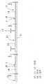
具体的に図7から図9で説明する。これは鉄道車両の側構体であり、ここでは3つの形材(中空形材)10,11,12を突き合せ、治具15上に載っている。車両構体の形材はもっと多いが、ここでは3枚とする。2つの接合部A,Bがある。形材10,11,12は面板14の上面に強度用のリブ17があるが、形材11のみに示し、他の形材10、12は省略している。リブには補強部材(図示せず)を溶接する。形材10,11,12の幅方向の端部の突き合せ部には凸部18が面板14の板厚の外方(図7の上方)に突出してある。 This will be specifically described with reference to FIGS. This is a side structure of a railway vehicle. Here, three profiles (hollow profiles) 10, 11, and 12 are abutted and placed on a
形材10の面板14の厚さが他の形材11,12の面板14の板厚よりも厚い。これは,形材10には窓(図示せず)があり、他の形材11,12には窓がないためである。このため、中央部の形材11の面板14は形材10側が形材10の面板14の厚さと同一であり、形材12との接合部側の板厚は形材12の面板14の厚さと同一である。 The thickness of the
形材10と形材11との突き合せ部Aの凸部18,18の突出代は同一である。凸部18,18の幅も同一である。凸部18の突出代は、回転工具30の大径部31と小径部32との境33が凸部18の内部に位置するようにして、摩擦攪拌接合するのを考慮している。小径部32と凸部18の重なり代が零(面板14の外面の延長線上に境33が位置する)であれば、面板14の外面がへこむため、これを除くために境33を凸部18内に位置させている。小径部32の長さは小径部32の先端が面板14の裏面(治具15)近傍に位置する長さである。 The protrusions of the
形材11と12との突き合せ部Bの凸部18、18の高さ、幅は同一であり、形材10、11の凸部の大きさと同一である。回転工具30の大径部31と小径部32との境33が凸部18の内部に位置するようにして、摩擦攪拌接合する。小径部32の長さは小径部32の先端が面板14の裏面(治具15)近傍に位置する長さである。 The heights and widths of the
面板14の板厚について一例を説明すると、形材10の面板14の板厚:4mm、形材12の面板13の板厚:3mm,形材11の面板14の板厚:形材10側が4mm,形材12側が3mmである。接合部Aの凸部18の突出代:2mm、接合部Bの凸部18の突出代2mmである。凸部18の幅:6.5mmである。 An example of the thickness of the
このため、回転工具30は接合部Aの回転工具30の小径部32の長さ:5mm、接合部Bの回転工具30の小径部32の長さ:3mmとなり、接合部A,Bに対応して小径部32の長さが異なる回転工具30が必要になる。 Therefore, the
このため、複数の摩擦接合個所がある場合、摩擦攪拌接合個所毎に回転工具を準備しなければならない。
本発明の目的は、回転工具30の大きさを同一にできるようにすることにある。For this reason, when there are a plurality of friction welding locations, a rotating tool must be prepared for each friction stir welding location.
An object of the present invention is to make the size of the
上記目的は、板部の両端部に板厚方向に突出する凸部を有する複数の部材を有し、隣接する部材の端部を突き合せて摩擦攪拌接合する摩擦攪拌接合方法において、部材は、一方の凸部に接続する板部の厚さと他方の凸部に接続する板部の厚さは異なる寸法を有し、板部の厚さ寸法と凸部の板部からの突出代の寸法の加算値は、複数の突き合わせ部において同一であり、前記複数の突き合わせ部を摩擦攪拌接合すること、によって達成できる。The above object has a plurality of members having a protrusion protruding in the thickness direction atboth endsof the plate portion,the friction stir welding method for friction stir welding butt ends of adjacent members, member The thickness of the plate portion connected to one convex portion and the thickness of the plate portion connected to the other convex portion have different dimensions, and the thickness dimension of the plate portion and the dimension of the protrusion margin from the plate portion of the convex portion Is the same in the plurality of butted portions and can be achieved by friction stir welding theplurality of butted portions .
以下、本発明の実施例を説明する。 Examples of the present invention will be described below.
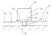
以下本発明の一実施例を図1から図3により説明する。図1において、形材10、11、12の面板14の厚さは図7と同一である。形材10の面板14の板厚は4mm、形材12の面板14の板厚は3mm、形材11の面板14の板厚は、形材10側が4mm、形材12側が3mmである。 An embodiment of the present invention will be described below with reference to FIGS. In FIG. 1, the thickness of the
形材10と形材11との接合部Aの凸部18、18の突出代は、2mm、形材12と形材11との接合部Bの凸部18、18の突出代は、3mmであり、接合部Bの凸部の突出代が接合部Aの凸部18の突出代よりも大きい。このため、複数の形材10,11における、凸部18,面板14を含む形材10,11の厚さは全て同一である。The protrusion margin of the
回転工具30の小径部32の長さは、全ての接合部A,Bの回転工具とも同一である。すなわち,接合部Bの回転工具30の小径部32の長さは、接合部Aの回転工具と同一である。小径部32の長さは、面板14の板厚が厚い個所の板厚よりも長い。具体的には、板厚14が厚い個所Aの板厚が4mmであれば、回転工具の小径部32の長さは5mmであり、凸部18と小径部32との重なり代は1mmである。板厚が薄い個所Bの板厚が3mmであれば、凸部18と小径部32との重なり代は2mmである。各接合部A,Bの回転工具30の大径部31の外径は同一である。小径部32の外径も同一である。The length of the
かかる構成において、各接合部A,Bに前記大きさの回転工具30を配置し、摩擦攪拌接合を行う。板厚が厚い個所の接合部Aでは回転工具の小径部32の挿入代が従来と同様のため、従来と同様に摩擦攪拌接合が行われる。 In such a configuration, the
板厚が薄い個所の接合部Bでは、小径部32と大径部31との境33を面板14の上面から1mm下方に位置させ、摩擦攪拌接合を行う。回転工具30の小径部32の挿入代は全て同一にする管理を行う。この下方1mmの挿入代は接合部A,Bで同一である。In the joint portion B where the plate thickness is thin, the
このため、接合部A、B毎に、回転工具30の大きさを変える必要がなく、また、回転工具30の挿入代も同一でよい。
したがって、作業を容易に行えるものである。For this reason, it is not necessary to change the magnitude | size of the
Therefore, the work can be easily performed.
凸部18側が構体の外面側であれば、摩擦攪拌接合後、凸部18を切削して除き、面板14の外面と同一面にする。If the
上記実施例では接合部毎に回転工具を配置し、同時に摩擦攪拌作業を行っているが、一方の接合部Aを摩擦攪拌接合し、次に他方の接合部Bを接合部Aに使用した回転工具30を用いて摩擦攪拌作業を行ってもよい。 In the above embodiment, a rotating tool is arranged for each joint, and the friction stir work is performed at the same time. However, one joint A is friction stir welded, and then the other joint B is used as the joint A. Friction stirring work may be performed using the
また、アルミ押し出し形材ではなく、他の部材にも適用できる。Further, instead of the aluminum extruded material, it can be appliedto other partsmaterial.
上記実施例はシングルスキン形材であったが、ダブルスキン形材(中空形材)であっても利用できる。中空形材は接合部の裏面が治具15に接していないので、回転工具30の接合厚さは明確に言えないが、基本的には板厚である。The above embodiments have had a single skin profile can be used even in doublepulse Kin profile (hollow profiles). In the hollow profile, since the back surface of the joint portion is not in contact with the
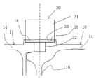
図4において、中空形材100、110、120は、2枚の実質的に平行な面板13,14と、面板13,14を接続する接続板16,17,形材の幅方向の端部の凸部18とからなる。形材100,110,120の面板13,14の厚さは図5の面板14の板厚と同一である。形材100の面板13,14の板厚は形材120の面板13,14の板厚よりも厚い(形材120の面板13,14の板厚は薄い)。形材110と120の接合部Bの近傍の形材110の面板13,14の板厚は薄く、形材100と110との接合部Aの近傍の形材110の面板13,14の板厚は厚い。4, the
突き合せ部の凸部18は面板13,14の端部に中空形材の外面に突出してある。凸部18の突出代は、接合部Aについては前記と同様である。接合部Bの凸部18の突出代については、接合部Aの突出代よりも大きい。複数の接合個所A,Bに用いる回転工具30,30の大きさ、および挿入代は全て同一である。具体的には、面板14の厚い個所の板厚が例えば4mmであれば、回転工具の小径部の長さは5mmであり、凸部18と小径部32との重なり代は約1mmである。板厚が薄い個所Bの面板13,14の板厚が3mmであれば、凸部18と小径部32との重なり代は約2mmである(小径部32の長さが5mmのため)。したがって、凸部18、面板13,14を含む形材100,110,120の厚さはすべて同一である。The protruding
回転工具の大径部31の外形は接合部Aの回転工具30と同一である。小径部32の外形も接合部Bの回転工具30と同一である。 The outer shape of the large-
接合部A,Bにおいて、一方の形材110,120の端部には他方の形材100,110の端部が嵌入している。接続板16の板厚の中心の延長線上に、凸部18,18(面板13,14)の端部がある。接続板16と凸部18(面板13,14)との接合部は凹部になっている。この凹部に他方の中空形材の面板13,14が入っている。In the joint portions A and B,the end portions of the
形材100,110,120は治具15に載っており、摩擦攪拌接合しない側の面板13の凸部18の頂面が治具15に載っている。 The
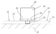
かかる構成において、各接合部に前記大きさの回転工具30をそれぞれ配置し、摩擦攪拌接合を行う。板厚が厚い個所の接合部Aでは回転工具の小径部32の挿入代が従来と同様のため、従来と同様に摩擦攪拌接合が行われる。 In such a configuration, the
板厚が薄い個所の接合部Bでは、小径部32と大径部31との境33を面板の上面から2mm上方に位置させ、摩擦攪拌接合を行う。挿入した回転工具30の挿入力は凸部18,18から、接続板16、凸部18,18を介して治具15に伝えられる。In the joint portion B where the plate thickness is thin, the
このため、接合部A、B毎に、回転工具30の大きさを変える必要がなく、また、回転工具30の挿入代も同一でよい。 For this reason, it is not necessary to change the magnitude | size of the
面板14側の摩擦攪拌接合が終了したら、形材100,110,120をうら返し、面板13側の凸部を上方に突出させ、同一の回転工具30を用い、同一の挿入量で摩擦攪拌接合を行う。When the friction stir welding on the
10,11,12,100,110,120:形材
13,14:面板
15:治具
18:凸部
30:回転工具
31:大径部
32:小径部
A、B:摩擦攪拌接合部10, 11, 12, 100, 110, 120:
Claims (2)
Translated fromJapanese部材は、一方の凸部に接続する板部の厚さと他方の凸部に接続する板部の厚さは異なる寸法を有し、
板部の厚さ寸法と凸部の板部からの突出代の寸法の加算値は、複数の突き合わせ部において同一であり、
前記複数の突き合わせ部を摩擦攪拌接合すること、
を特徴とする摩擦攪拌接合方法。In the friction stir welding method having a plurality of members having convex portions protruding in the plate thickness direction at both ends of the plate portion, and abutting the end portions of the adjacent members to friction stir welding,
The member has a dimension in which the thickness of the plate portion connected to one convex portion and the thickness of the plate portion connected to the other convex portion are different,
The added value of the thickness dimension of the plate part and the dimension of the protrusion margin from the plate part of the convex part is the same in the plurality of butted parts,
Friction stir welding the plurality of butted portions;
A friction stir welding method characterized by the above.
中空形材は、一方の凸部に接続する板部の厚さと他方の凸部に接続する板部の厚さは異なる寸法を有し、
板部の厚さ寸法と凸部の板部からの突出代の寸法の加算値は、複数の突き合わせ部において同一であり、
前記複数の突き合わせ部を摩擦攪拌接合すること、
を特徴とする摩擦攪拌接合方法。Two substantially parallel plate portions, a connecting plate for connecting both, and a plurality of hollow shapes having convex portions projecting in the thickness direction at both ends of each plate portion, and adjacent hollow shapes In the friction stir welding method in which the ends of the material are butted and friction stir welding is performed,
The hollow shape member has a dimension in which the thickness of the plate portion connected to one convex portion and the thickness of the plate portion connected to the other convex portion are different from each other,
The added value of the thickness dimension of the plate part and the dimension of the protrusion margin from the plate part of the convex part is the same in the plurality of butted parts,
Friction stir welding the plurality of butted portions;
A friction stir welding method characterized by the above.
Priority Applications (7)
| Application Number | Priority Date | Filing Date | Title |
|---|---|---|---|
| JP2003312669AJP4205537B2 (en) | 2003-09-04 | 2003-09-04 | Friction stir welding method |
| US10/791,857US7121450B2 (en) | 2003-09-04 | 2004-03-04 | Friction stir welding method and group of shape members for friction stir welding |
| AT04251293TATE511424T1 (en) | 2003-09-04 | 2004-03-05 | ROTATING FRICTION WELDING METHOD AND GROUP OF ELEMENTS TO BE WELDED |
| EP04251293AEP1512488B1 (en) | 2003-09-04 | 2004-03-05 | Friction stir welding method and group of shape members for friction stir welding |
| CNB2004100559303ACN1287944C (en) | 2003-09-04 | 2004-07-30 | Friction stir welding method and group of shape members for friction stir welding |
| KR1020040060156AKR100646692B1 (en) | 2003-09-04 | 2004-07-30 | Friction stir welding method and group of shape members for friction stir welding |
| US11/519,894US7601432B2 (en) | 2003-09-04 | 2006-09-13 | Friction stir welding method and group of shape members for friction stir welding |
Applications Claiming Priority (1)
| Application Number | Priority Date | Filing Date | Title |
|---|---|---|---|
| JP2003312669AJP4205537B2 (en) | 2003-09-04 | 2003-09-04 | Friction stir welding method |
Related Child Applications (2)
| Application Number | Title | Priority Date | Filing Date |
|---|---|---|---|
| JP2008130360ADivisionJP4607207B2 (en) | 2008-05-19 | 2008-05-19 | Friction stir welding method |
| JP2008130359ADivisionJP4607206B2 (en) | 2008-05-19 | 2008-05-19 | Friction stir welding shape and friction stir welding structure |
Publications (2)
| Publication Number | Publication Date |
|---|---|
| JP2005081350A JP2005081350A (en) | 2005-03-31 |
| JP4205537B2true JP4205537B2 (en) | 2009-01-07 |
Family
ID=34131866
Family Applications (1)
| Application Number | Title | Priority Date | Filing Date |
|---|---|---|---|
| JP2003312669AExpired - LifetimeJP4205537B2 (en) | 2003-09-04 | 2003-09-04 | Friction stir welding method |
Country Status (6)
| Country | Link |
|---|---|
| US (2) | US7121450B2 (en) |
| EP (1) | EP1512488B1 (en) |
| JP (1) | JP4205537B2 (en) |
| KR (1) | KR100646692B1 (en) |
| CN (1) | CN1287944C (en) |
| AT (1) | ATE511424T1 (en) |
Families Citing this family (10)
| Publication number | Priority date | Publication date | Assignee | Title |
|---|---|---|---|---|
| CN1165403C (en) | 1996-03-19 | 2004-09-08 | 株式会社日立制作所 | Components for friction welding |
| KR100922043B1 (en)* | 2007-08-22 | 2009-10-19 | 대한소결금속 주식회사 | Friction Bonding Method of Dissimilar Materials |
| US20100199590A1 (en)* | 2009-02-06 | 2010-08-12 | Aar Corp. | Aircraft Cargo Pallet and Method of Manufacture |
| WO2011089704A1 (en)* | 2010-01-22 | 2011-07-28 | トヨタ自動車株式会社 | Welded structure and welding method |
| US9468990B2 (en)* | 2011-06-22 | 2016-10-18 | Sapa Ab | Friction stir welding tool with shoulders having different areas; methods using such tool; product welded with such tool |
| WO2013082505A1 (en)* | 2011-12-01 | 2013-06-06 | The Trustees Of The University Of Pennsylvania | A non-blood contacting mechanical device that improves heart function after injury |
| USD845061S1 (en) | 2018-10-16 | 2019-04-09 | E. Mishan & Sons, Inc. | Egg pan |
| USD883024S1 (en) | 2019-02-11 | 2020-05-05 | E. Mishan & Sons, Inc. | Egg pan cover |
| USD883025S1 (en) | 2019-02-11 | 2020-05-05 | E. Mishan & Sons, Inc. | Egg pan cover |
| US11872650B2 (en) | 2020-05-15 | 2024-01-16 | Lockheed Martin Corporation | Systems and methods for friction stir welding a cold plate |
Family Cites Families (11)
| Publication number | Priority date | Publication date | Assignee | Title |
|---|---|---|---|---|
| JP3014654B2 (en) | 1996-03-19 | 2000-02-28 | 株式会社日立製作所 | Friction joining method |
| JPH10193143A (en) | 1997-01-17 | 1998-07-28 | Showa Alum Corp | Friction stir welding |
| JP3897391B2 (en)* | 1997-03-25 | 2007-03-22 | 昭和電工株式会社 | Friction stir welding method for metal joining members |
| JP3070735B2 (en) | 1997-07-23 | 2000-07-31 | 株式会社日立製作所 | Friction stir welding method |
| JP3589863B2 (en)* | 1997-07-23 | 2004-11-17 | 株式会社日立製作所 | Structure and friction stir welding method |
| US6745929B1 (en) | 1998-06-16 | 2004-06-08 | Hitachi, Ltd. | Method of manufacturing structural body and structural body |
| AU733140B2 (en)* | 1998-09-29 | 2001-05-10 | Hitachi Limited | A friction stir welding method |
| JP2000153374A (en) | 1998-11-18 | 2000-06-06 | Hitachi Ltd | Friction stir welding device, friction stir welding tool, and friction stir welding structure |
| TW464576B (en)* | 1999-05-28 | 2001-11-21 | Hitachi Ltd | A structure body and a manufacturing method of a structure body |
| JP3552978B2 (en)* | 2000-01-27 | 2004-08-11 | 株式会社日立製作所 | Hollow profile |
| JP2002224858A (en)* | 2001-01-31 | 2002-08-13 | Kobe Steel Ltd | Joining method for different thickness joint |
- 2003
- 2003-09-04JPJP2003312669Apatent/JP4205537B2/ennot_activeExpired - Lifetime
- 2004
- 2004-03-04USUS10/791,857patent/US7121450B2/ennot_activeExpired - Fee Related
- 2004-03-05ATAT04251293Tpatent/ATE511424T1/ennot_activeIP Right Cessation
- 2004-03-05EPEP04251293Apatent/EP1512488B1/ennot_activeExpired - Lifetime
- 2004-07-30CNCNB2004100559303Apatent/CN1287944C/ennot_activeExpired - Fee Related
- 2004-07-30KRKR1020040060156Apatent/KR100646692B1/ennot_activeExpired - Fee Related
- 2006
- 2006-09-13USUS11/519,894patent/US7601432B2/ennot_activeExpired - Fee Related
Also Published As
| Publication number | Publication date |
|---|---|
| EP1512488B1 (en) | 2011-06-01 |
| CN1590005A (en) | 2005-03-09 |
| CN1287944C (en) | 2006-12-06 |
| JP2005081350A (en) | 2005-03-31 |
| US20050051601A1 (en) | 2005-03-10 |
| US7601432B2 (en) | 2009-10-13 |
| US7121450B2 (en) | 2006-10-17 |
| US20070007321A1 (en) | 2007-01-11 |
| KR100646692B1 (en) | 2006-11-23 |
| EP1512488A1 (en) | 2005-03-09 |
| KR20050025249A (en) | 2005-03-14 |
| ATE511424T1 (en) | 2011-06-15 |
Similar Documents
| Publication | Publication Date | Title |
|---|---|---|
| JP3751237B2 (en) | Friction stir welding connection material | |
| CN100441357C (en) | Friction Stir Welding Method | |
| US7601432B2 (en) | Friction stir welding method and group of shape members for friction stir welding | |
| JP6248790B2 (en) | Friction stir welding method | |
| US20020060237A1 (en) | Friction stir bonding method | |
| US6557746B2 (en) | Friction stir bonding method | |
| JP2002316273A (en) | Friction stir welding method | |
| JP3978257B2 (en) | Workpiece joining method by friction stir welding | |
| JP2002153982A (en) | Friction stir welding method | |
| KR20060088465A (en) | Friction Stir Welding | |
| JP5090132B2 (en) | Manufacturing method and bonded structure of bonded product | |
| JP3954547B2 (en) | Friction stir welding method and friction stir welding | |
| JP2001162383A (en) | Friction stir welding | |
| JP3556888B2 (en) | Hollow sections for friction stir welding | |
| JP4607206B2 (en) | Friction stir welding shape and friction stir welding structure | |
| JP4607207B2 (en) | Friction stir welding method | |
| CN102814589B (en) | Joining method and method for manufacturing joined structure | |
| JP2002066764A (en) | Friction stir welding method | |
| JP4440522B2 (en) | Hollow profile for friction stir welding | |
| JP5203311B2 (en) | Friction stir welding structure and friction stir welding method | |
| JP2009172650A (en) | Manufacturing method of joined structure | |
| JP2009119488A (en) | Joining method | |
| JP2005118829A (en) | Friction stir welding joint structure | |
| JP2009195949A (en) | Manufacturing method of joined structure | |
| JP2007260722A (en) | Welded structure of cylindrical member |
Legal Events
| Date | Code | Title | Description |
|---|---|---|---|
| A131 | Notification of reasons for refusal | Free format text:JAPANESE INTERMEDIATE CODE: A131 Effective date:20060905 | |
| A521 | Request for written amendment filed | Free format text:JAPANESE INTERMEDIATE CODE: A523 Effective date:20061012 | |
| A131 | Notification of reasons for refusal | Free format text:JAPANESE INTERMEDIATE CODE: A131 Effective date:20070410 | |
| A521 | Request for written amendment filed | Free format text:JAPANESE INTERMEDIATE CODE: A523 Effective date:20070608 | |
| A131 | Notification of reasons for refusal | Free format text:JAPANESE INTERMEDIATE CODE: A131 Effective date:20080318 | |
| A521 | Request for written amendment filed | Free format text:JAPANESE INTERMEDIATE CODE: A523 Effective date:20080519 | |
| TRDD | Decision of grant or rejection written | ||
| A01 | Written decision to grant a patent or to grant a registration (utility model) | Free format text:JAPANESE INTERMEDIATE CODE: A01 Effective date:20081014 | |
| A01 | Written decision to grant a patent or to grant a registration (utility model) | Free format text:JAPANESE INTERMEDIATE CODE: A01 | |
| A61 | First payment of annual fees (during grant procedure) | Free format text:JAPANESE INTERMEDIATE CODE: A61 Effective date:20081016 | |
| FPAY | Renewal fee payment (event date is renewal date of database) | Free format text:PAYMENT UNTIL: 20111024 Year of fee payment:3 | |
| R150 | Certificate of patent or registration of utility model | Free format text:JAPANESE INTERMEDIATE CODE: R150 Ref document number:4205537 Country of ref document:JP Free format text:JAPANESE INTERMEDIATE CODE: R150 | |
| FPAY | Renewal fee payment (event date is renewal date of database) | Free format text:PAYMENT UNTIL: 20121024 Year of fee payment:4 | |
| FPAY | Renewal fee payment (event date is renewal date of database) | Free format text:PAYMENT UNTIL: 20121024 Year of fee payment:4 | |
| FPAY | Renewal fee payment (event date is renewal date of database) | Free format text:PAYMENT UNTIL: 20131024 Year of fee payment:5 | |
| EXPY | Cancellation because of completion of term |