JP4204128B2 - Substrate transport apparatus and substrate transport method - Google Patents
Substrate transport apparatus and substrate transport methodDownload PDFInfo
- Publication number
- JP4204128B2 JP4204128B2JP00861699AJP861699AJP4204128B2JP 4204128 B2JP4204128 B2JP 4204128B2JP 00861699 AJP00861699 AJP 00861699AJP 861699 AJP861699 AJP 861699AJP 4204128 B2JP4204128 B2JP 4204128B2
- Authority
- JP
- Japan
- Prior art keywords
- transfer
- substrate
- pair
- arms
- transport
- Prior art date
- Legal status (The legal status is an assumption and is not a legal conclusion. Google has not performed a legal analysis and makes no representation as to the accuracy of the status listed.)
- Expired - Fee Related
Links
- 239000000758substrateSubstances0.000titleclaimsdescription98
- 238000000034methodMethods0.000titleclaimsdescription11
- 238000012546transferMethods0.000claimsdescription97
- 238000012545processingMethods0.000claimsdescription8
- 230000002093peripheral effectEffects0.000claimsdescription6
- 230000032258transportEffects0.000claims9
- 239000011521glassSubstances0.000description26
- 238000005452bendingMethods0.000description4
- 239000004973liquid crystal related substanceSubstances0.000description4
- 238000005336crackingMethods0.000description2
- 238000012423maintenanceMethods0.000description2
- 239000011248coating agentSubstances0.000description1
- 238000000576coating methodMethods0.000description1
- 238000011161developmentMethods0.000description1
- 238000001035dryingMethods0.000description1
- 230000000694effectsEffects0.000description1
- 230000002452interceptive effectEffects0.000description1
- 229920002120photoresistant polymerPolymers0.000description1
- 238000001179sorption measurementMethods0.000description1
Images


Classifications
- B—PERFORMING OPERATIONS; TRANSPORTING
- B65—CONVEYING; PACKING; STORING; HANDLING THIN OR FILAMENTARY MATERIAL
- B65G—TRANSPORT OR STORAGE DEVICES, e.g. CONVEYORS FOR LOADING OR TIPPING, SHOP CONVEYOR SYSTEMS OR PNEUMATIC TUBE CONVEYORS
- B65G25/00—Conveyors comprising a cyclically-moving, e.g. reciprocating, carrier or impeller which is disengaged from the load during the return part of its movement
- B65G25/04—Conveyors comprising a cyclically-moving, e.g. reciprocating, carrier or impeller which is disengaged from the load during the return part of its movement the carrier or impeller having identical forward and return paths of movement, e.g. reciprocating conveyors
- H—ELECTRICITY
- H01—ELECTRIC ELEMENTS
- H01L—SEMICONDUCTOR DEVICES NOT COVERED BY CLASS H10
- H01L21/00—Processes or apparatus adapted for the manufacture or treatment of semiconductor or solid state devices or of parts thereof
- H01L21/67—Apparatus specially adapted for handling semiconductor or electric solid state devices during manufacture or treatment thereof; Apparatus specially adapted for handling wafers during manufacture or treatment of semiconductor or electric solid state devices or components ; Apparatus not specifically provided for elsewhere
- H01L21/677—Apparatus specially adapted for handling semiconductor or electric solid state devices during manufacture or treatment thereof; Apparatus specially adapted for handling wafers during manufacture or treatment of semiconductor or electric solid state devices or components ; Apparatus not specifically provided for elsewhere for conveying, e.g. between different workstations
Landscapes
- Engineering & Computer Science (AREA)
- Mechanical Engineering (AREA)
- Container, Conveyance, Adherence, Positioning, Of Wafer (AREA)
- Warehouses Or Storage Devices (AREA)
Description
Translated fromJapanese【0001】
【発明の属する技術分野】
本発明は例えば液晶表示装置用のガラス基板等の角基板を搬送する装置及び搬送方法に関する。
【0002】
【従来の技術】
液晶表示装置用のガラス基板は1枚の大寸法のガラス基板にホトレジストを塗布・乾燥し、更に露光、現像等の処理を施し、最終的に製品寸法のガラス基板を切り出している。
【0003】
大寸法のガラス基板に各種処理を施すには、1つの処理ステーションでの処理が終了した後、搬送装置で他の処理ステーションへ大寸法のガラス基板を搬送するようにしている。
図7(a)及び(b)は従来の搬送装置の平面図と側面図であり、搬送装置は一対の搬送アーム100に角基板Wの側辺部下面を支持するフック101…を設けた構造となっている。
【0004】
【発明が解決しようとする課題】
上述した搬送装置を用いて角基板Wを搬送するには、ピンやチャック等の支持治具102にて支持されている角基板Wよりも搬送アーム100のフック101…が若干低くなるように搬送装置の高さを調整し、次いで搬送アーム100を水平方向に移動してフック101…を角基板Wの下に入り込ませ、この後搬送アーム100を上昇させるか或いは支持治具102を下降させることでフック101…にて角基板Wを保持し、この状態で搬送アーム100をスライド移動することで角基板Wを次ステーションへ移送するようにしている。
【0005】
しかしながら、液晶表示装置用のガラス基板等にあっては、厚みが0.7mm程度と薄く大面積となるので、図7(b)に示すように自重によって基板中央部が撓んで大きく垂れ下がり、支持治具に干渉して搬送できなくなったり、基板の割れが発生する。
【0006】
特に最近では、液晶表示装置の表示部の寸法が大きくなる傾向にありこれに伴って切り出し前のガラス基板の寸法も一辺が1000mmを越すものも利用され、例えば寸法が960mm×1100mm×0.7mmのガラス基板を従来の搬送装置で持ち上げると、中央部で約100mmも撓んでしまう。
【0007】
【課題を解決するための手段】
上記課題を解決すべく本発明に係る角基板を搬送する基板搬送装置及び基板搬送方法は、一対の搬送アームを備え、この一対の搬送アームは水平方向に開閉動するとともに水平方向にスライド移動し、更に一対の搬送アームは搬送方向と直交する角基板の周辺部を下から保持する第1の保持部と、搬送方向と平行な角基板の周辺部を下から保持する第2の保持部とを備えた構成とした。
斯かる構成とすることで、基板中央部の撓み量を抑えることができ、他の部材との干渉や基板の割れが防止できる。
【0008】
上記の基板搬送装置において、第1の保持部及び第2の保持部の寸法を、角基板の略四辺を保持する寸法とすることで、更に基板中央部の撓み量を小さくすることができる。
【0009】
また、一対の搬送アームについては水平動のみを行わせ、角基板を支持するチャック或いはピンに昇降動を行わせてもよいが、搬送アームにも昇降動を行わせることで、効率のよい搬送が行える。
【0010】
また、待機位置において、一対の搬送アーム同士若しくは隣接する一対の搬送アームの一方と上下方向に重なるような構成とすることで、スペースの有効利用が図れる。
【0011】
更に、上記の基板搬送装置を用いた基板搬送方法は、チャックやピン等の支持治具にて角基板を下方から支持し、この状態の角基板よりも一対の搬送アームを上方に位置せしめるとともに一対の搬送アームを搬送方向を基準として角基板よりも拡開し、次いで相対的に角基板よりも一対の搬送アームを下方に位置せしめ、この後、一対の搬送アームを閉じ、更に角基板を一対の搬送アームに対して相対的に下降せしめることで一対の搬送アームの第1及び第2の保持部にて角基板の下面周辺部を保持し、支持治具を一対の搬送アームに対して相対的に下方に位置せしめた後、角基板を保持した一対の搬送アームをスライド移動せしめる。
【0012】
尚、一対の搬送アームを角基板よりも上方に位置せしめるとともに搬送方向を基準として角基板よりも拡開するには、一対の搬送アームの両方を動作させてもよいし片方のみを動作させてもよい。
【0013】
【発明の実施の形態】
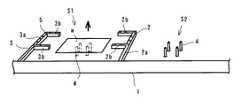
以下に本発明の実施の形態を添付図面に基づいて説明する。ここで、図1は本発明に係る基板搬送装置の待機状態を示す斜視図、図2は同基板搬送装置の一対の搬送アームが開いた状態を示す斜視図、図3は同基板搬送装置の一対の搬送アームが相対的に角基板よりも下方に位置した状態を示す斜視図、図4は同基板搬送装置の一対の搬送アームが閉じた状態を示す斜視図、図5は同基板搬送装置の一対の搬送アームが角基板を保持した状態を示す斜視図、図6は同基板搬送装置の一対の搬送アームが角基板を保持したままスライド移動した状態を示す斜視図である。
【0014】
先ず、本発明に係る搬送装置の構成は、処理ステーションS1,S2に沿ってガイドレール1が設けられ、このガイドレール1に一対の搬送アーム2,3が取り付けられている。
尚、図示例では一対の搬送アームを取り付けたが、複数対の搬送アームを取り付けるようにしてもよい。
【0015】
搬送アーム2,3は搬送方向と直交する方向に延びる第1の保持部2a,3aと、搬送方向と平行に第1の保持部から延びる第2の保持部2b,3bとからなる。そして、搬送アーム2の第2の保持部2b,2bの間隔及び搬送アーム3の第2の保持部3b,3bの間隔はガラス基板Wの幅方向寸法よりも若干短く設定され、また第2の保持部2b,2b,3b,3bは互いに向い合う方向に延び、その長さはガラス基板Wの搬送方向寸法の1/2よりも若干短く設定されている。
【0016】
また、搬送アーム2,3は独立して昇降動、水平方向の開閉動及びガイドレール1に沿ったスライド移動が可能とされている。尚、搬送アーム2,3については独立して昇降動しないものであっても、ガラス基板Wを支持するピンやチャック等の支持治具4の昇降動作を細かく設定することで、支障なくガラス基板Wを搬送することができる。
【0017】
次に、搬送方法について図1の待機状態を出発点として説明する。先ず待機状態にあっては搬送アーム2,3が上下方向に重なっている。このようにすることで、スペースの有効利用が図れる。
また待機状態では、搬送アーム2,3の方がガラス基板Wよりも上方位置にある。
【0018】
次いで、一方の搬送アーム2がガラス基板Wの上方を通過して反対側までスライド移動する。この移動により図2に示すように、搬送アーム2,3の搬送方向の間隔がガラス基板Wの搬送方向の長さよりも大きくなる。
【0019】
次いで、搬送アーム2,3を下降させるかガラス基板Wを上昇させて、図3に示すように、搬送アーム2,3の方がガラス基板Wよりも下方位置になるようにする。尚、この時、搬送アーム2,3の高さ位置も揃えておく。
【0020】
この後、搬送アーム2,3を閉じる。即ち、水平方向に互いに近づく方向に移動する。移動する量は、平面視でガラス基板Wの四辺部と搬送アーム2,3の第1及び第2の保持部2a,2b,3a,3bとが重なる量とする。
【0021】
そして、上記の状態から搬送アーム2,3を上昇させるか支持治具4を下降させることで、図5に示すように、ガラス基板Wの四辺部を搬送アーム2,3の第1及び第2の保持部2a,2b,3a,3bで下方から保持する。即ち、ガラス基板Wはその下面の略全周が搬送アームにて保持された状態になる。
【0022】
このとき、保持部2a,2b,3a,3bには真空吸着用の孔5が多数形成されているので、ガラス基板を保持すると同時に真空吸着を行い、搬送時にガラス基板がずれないようにする。
【0023】
次いで、搬送アーム2,3と支持治具4とが干渉しない位置まで搬送アーム2,3を上昇させるか支持治具4を下降させ、図6に示すように、搬送アーム2,3を一体的に、即ち、搬送アーム2,3の位置関係を崩すことなく同期して処理ステーションS2までスライド移動する。
この後は、処理ステーションS2の支持治具4に前記と逆の動作にて受け渡して、元の待機位置に戻ることで搬送作業が終了する。
【0024】
【発明の効果】
以上に説明したように本発明に係る角基板を搬送する基板搬送装置によれば、一対の搬送アームに、搬送方向と直交する角基板の周辺部を下から保持する第1の保持部と、搬送方向と平行な角基板の周辺部を下から保持する第2の保持部とを設けたので、角基板の四辺部若しくは略四辺部を下方から保持するため、基板中央部の撓み量を抑え、他の部材との干渉や基板の割れが防止できる。
【0025】
具体的には、960mm×1100mm×0.7mmのガラス基板を従来の搬送装置で搬送する場合には、中央部で100mmの撓みが生じたが、本発明に係る搬送装置を用いた場合には、中央部での撓み量は10mm以下になった。
【0026】
また、待機位置において、一対の搬送アーム同士若しくは隣接する一対の搬送アームの一方と上下方向に重なるような構成とすることで、スペースの有効利用が図れる。
【図面の簡単な説明】
【図1】本発明に係る基板搬送装置の待機状態を示す斜視図
【図2】同基板搬送装置の一対の搬送アームが開いた状態を示す斜視図
【図3】同基板搬送装置の一対の搬送アームが相対的に角基板よりも下方に位置した状態を示す斜視図
【図4】同基板搬送装置の一対の搬送アームが閉じた状態を示す斜視図
【図5】同基板搬送装置の一対の搬送アームが角基板を保持した状態を示す斜視図
【図6】同基板搬送装置の一対の搬送アームが角基板を保持したままスライド移動した状態を示す斜視図
【図7】(a)は従来の搬送装置の平面図、(b)は従来の搬送装置の側面図
【符号の説明】
1…ガイドレール、2,3…搬送アーム、2a,3a…第1の保持部、2b,3b…第2の保持部、4…支持治具、5…吸着用の孔、S1,S2…処理ステーション、W…ガラス基板。[0001]
BACKGROUND OF THE INVENTION
The present invention relates to an apparatus and a transport method for transporting a square substrate such as a glass substrate for a liquid crystal display device.
[0002]
[Prior art]
A glass substrate for a liquid crystal display device is obtained by coating and drying a photoresist on a single large-sized glass substrate, further performing exposure, development, and the like, and finally cutting out a glass substrate having a product size.
[0003]
In order to perform various kinds of processing on a large-sized glass substrate, after the processing at one processing station is completed, the large-sized glass substrate is transported to another processing station by a transport device.
FIGS. 7A and 7B are a plan view and a side view of a conventional transfer device, and the transfer device has a structure in which a pair of
[0004]
[Problems to be solved by the invention]
In order to transport the square substrate W using the above-described transport device, the
[0005]
However, a glass substrate for a liquid crystal display or the like has a thin and large area of about 0.7 mm, so that the central portion of the substrate is bent and droops greatly by its own weight as shown in FIG. Interfering with the jig makes it impossible to transport or breaks the substrate.
[0006]
In particular, recently, the size of the display portion of the liquid crystal display device tends to increase, and accordingly, the size of the glass substrate before cutting out is also used that has a side exceeding 1000 mm. For example, the size is 960 mm × 1100 mm × 0.7 mm. When the glass substrate is lifted by a conventional transfer apparatus, the glass substrate is bent about 100 mm at the center.
[0007]
[Means for Solving the Problems]
In order to solve the above problems, a substrate transport apparatus and a substrate transport method for transporting a square substrate according to the present invention include a pair of transport arms, and the pair of transport arms opens and closes in the horizontal direction and slides in the horizontal direction. The pair of transfer arms further includes a first holding unit that holds the peripheral part of the square substrate perpendicular to the transfer direction from below, and a second holding unit that holds the peripheral part of the square substrate parallel to the transfer direction from below. It was set as the structure provided with.
With such a configuration, it is possible to suppress the amount of bending at the center of the substrate, and to prevent interference with other members and cracking of the substrate.
[0008]
In the substrate transport apparatus described above, the first holding portion and the second holding portion are dimensioned to hold approximately four sides of the square substrate, whereby the amount of bending at the central portion of the substrate can be further reduced.
[0009]
The pair of transfer arms may be moved only horizontally and the chuck or pin supporting the square substrate may be moved up and down. However, the transfer arm can also be moved up and down for efficient transfer. Can be done.
[0010]
In addition, in the standby position, the space can be effectively used by overlapping the pair of transfer arms or one of the adjacent pair of transfer arms in the vertical direction.
[0011]
Further, in the substrate transport method using the substrate transport apparatus, the square substrate is supported from below by a support jig such as a chuck or a pin, and the pair of transport arms are positioned above the square substrate in this state. The pair of transfer arms is expanded more than the square substrate with respect to the transfer direction, and then the pair of transfer arms is relatively positioned below the square substrate. Thereafter, the pair of transfer arms is closed, and the square substrate is further closed. The lower peripheral portion of the square substrate is held by the first and second holding portions of the pair of transfer arms by being lowered relative to the pair of transfer arms, and the support jig is held with respect to the pair of transfer arms. After being positioned relatively downward, the pair of transfer arms holding the square substrate is slid.
[0012]
In order to position the pair of transfer arms above the square substrate and to expand the square substrate with respect to the transfer direction, both the pair of transfer arms may be operated or only one of them may be operated. Also good.
[0013]
DETAILED DESCRIPTION OF THE INVENTION
Embodiments of the present invention will be described below with reference to the accompanying drawings. Here, FIG. 1 is a perspective view showing a standby state of the substrate transfer apparatus according to the present invention, FIG. 2 is a perspective view showing a state where a pair of transfer arms of the substrate transfer apparatus is opened, and FIG. FIG. 4 is a perspective view showing a state in which a pair of transfer arms of the substrate transfer apparatus is closed, and FIG. 5 is a perspective view showing a state in which the pair of transfer arms is closed. FIG. 6 is a perspective view showing a state in which the pair of transfer arms of the substrate transfer apparatus slides while holding the square substrate.
[0014]
First, in the configuration of the transfer apparatus according to the present invention, a
In the illustrated example, a pair of transfer arms is attached, but a plurality of pairs of transfer arms may be attached.
[0015]
The
[0016]
Further, the
[0017]
Next, the transport method will be described with the standby state in FIG. 1 as a starting point. First, in the standby state, the
In the standby state, the
[0018]
Next, one
[0019]
Next, the
[0020]
Thereafter, the
[0021]
Then, by raising the
[0022]
At this time, since the holding
[0023]
Next, the
Thereafter, the transfer operation is completed by transferring the wafer to the
[0024]
【The invention's effect】
As described above, according to the substrate transport apparatus for transporting the square substrate according to the present invention, the first holding portion that holds the peripheral portion of the square substrate perpendicular to the transport direction from below on the pair of transport arms, Since the second holding part that holds the peripheral part of the square substrate parallel to the transport direction from below is provided, the four sides or substantially four sides of the square board are held from below, so that the amount of bending at the central part of the substrate is suppressed. Interference with other members and cracking of the substrate can be prevented.
[0025]
Specifically, when a glass substrate having a size of 960 mm × 1100 mm × 0.7 mm is transported by a conventional transport device, a deflection of 100 mm occurs in the center, but when the transport device according to the present invention is used. The amount of bending at the center was 10 mm or less.
[0026]
In addition, in the standby position, the space can be effectively used by overlapping the pair of transfer arms or one of the adjacent pair of transfer arms in the vertical direction.
[Brief description of the drawings]
FIG. 1 is a perspective view showing a standby state of a substrate transfer apparatus according to the present invention. FIG. 2 is a perspective view showing a state in which a pair of transfer arms of the substrate transfer apparatus is opened. FIG. 4 is a perspective view showing a state in which the transfer arms are positioned relatively below the square substrate. FIG. 4 is a perspective view showing a state in which the pair of transfer arms of the substrate transfer apparatus is closed. FIG. 6 is a perspective view showing a state in which a pair of transfer arms of the substrate transfer apparatus is slidingly moved while holding the square substrate. FIG. Plan view of a conventional transport device, (b) is a side view of a conventional transport device.
DESCRIPTION OF
Claims (4)
Translated fromJapanesePriority Applications (3)
| Application Number | Priority Date | Filing Date | Title |
|---|---|---|---|
| JP00861699AJP4204128B2 (en) | 1999-01-18 | 1999-01-18 | Substrate transport apparatus and substrate transport method |
| US09/483,239US6247579B1 (en) | 1999-01-18 | 2000-01-14 | Substrate transfer apparatus and method of substrate transfer |
| TW089100748ATW440901B (en) | 1999-01-18 | 2000-01-18 | Substrate transfer apparatus and method of substrate transfer |
Applications Claiming Priority (1)
| Application Number | Priority Date | Filing Date | Title |
|---|---|---|---|
| JP00861699AJP4204128B2 (en) | 1999-01-18 | 1999-01-18 | Substrate transport apparatus and substrate transport method |
Publications (2)
| Publication Number | Publication Date |
|---|---|
| JP2000208587A JP2000208587A (en) | 2000-07-28 |
| JP4204128B2true JP4204128B2 (en) | 2009-01-07 |
Family
ID=11697893
Family Applications (1)
| Application Number | Title | Priority Date | Filing Date |
|---|---|---|---|
| JP00861699AExpired - Fee RelatedJP4204128B2 (en) | 1999-01-18 | 1999-01-18 | Substrate transport apparatus and substrate transport method |
Country Status (3)
| Country | Link |
|---|---|
| US (1) | US6247579B1 (en) |
| JP (1) | JP4204128B2 (en) |
| TW (1) | TW440901B (en) |
Families Citing this family (20)
| Publication number | Priority date | Publication date | Assignee | Title |
|---|---|---|---|---|
| JP4244555B2 (en)* | 2002-02-25 | 2009-03-25 | 東京エレクトロン株式会社 | Support mechanism for workpiece |
| US7019819B2 (en) | 2002-11-13 | 2006-03-28 | Molecular Imprints, Inc. | Chucking system for modulating shapes of substrates |
| US7641840B2 (en)* | 2002-11-13 | 2010-01-05 | Molecular Imprints, Inc. | Method for expelling gas positioned between a substrate and a mold |
| US8334967B2 (en)* | 2004-05-28 | 2012-12-18 | Board Of Regents, The University Of Texas System | Substrate support system having a plurality of contact lands |
| WO2005118914A2 (en)* | 2004-05-28 | 2005-12-15 | Board Of Regents, The University Of Texas System | Substrate support system and method |
| US7161663B2 (en)* | 2004-07-22 | 2007-01-09 | Asml Netherlands B.V. | Lithographic apparatus |
| US7636999B2 (en)* | 2005-01-31 | 2009-12-29 | Molecular Imprints, Inc. | Method of retaining a substrate to a wafer chuck |
| US7798801B2 (en)* | 2005-01-31 | 2010-09-21 | Molecular Imprints, Inc. | Chucking system for nano-manufacturing |
| US7635263B2 (en)* | 2005-01-31 | 2009-12-22 | Molecular Imprints, Inc. | Chucking system comprising an array of fluid chambers |
| US7670530B2 (en) | 2006-01-20 | 2010-03-02 | Molecular Imprints, Inc. | Patterning substrates employing multiple chucks |
| MY144847A (en) | 2005-12-08 | 2011-11-30 | Molecular Imprints Inc | Method and system for double-sided patterning of substrates |
| US8215946B2 (en) | 2006-05-18 | 2012-07-10 | Molecular Imprints, Inc. | Imprint lithography system and method |
| WO2009119580A1 (en) | 2008-03-25 | 2009-10-01 | Toshima Masato | Processing apparatus and processing method |
| JP5330721B2 (en) | 2007-10-23 | 2013-10-30 | オルボテック エルティ ソラー,エルエルシー | Processing apparatus and processing method |
| JP5373517B2 (en)* | 2009-09-14 | 2013-12-18 | 株式会社ディスコ | Conveying mechanism and processing device |
| JP5835722B2 (en) | 2009-12-10 | 2015-12-24 | オルボテック エルティ ソラー,エルエルシー | Automatic ranking multi-directional serial processor |
| US8459276B2 (en) | 2011-05-24 | 2013-06-11 | Orbotech LT Solar, LLC. | Broken wafer recovery system |
| JP6100486B2 (en)* | 2012-08-17 | 2017-03-22 | 株式会社プレテック | Immersion cleaning device |
| JP6418932B2 (en)* | 2014-12-15 | 2018-11-07 | 東京応化工業株式会社 | Ultraviolet irradiation apparatus, ultraviolet irradiation method, substrate processing apparatus, and manufacturing method of substrate processing apparatus |
| JP7315820B2 (en)* | 2019-03-28 | 2023-07-27 | 株式会社東京精密 | Work transfer device |
Family Cites Families (7)
| Publication number | Priority date | Publication date | Assignee | Title |
|---|---|---|---|---|
| US3973665A (en)* | 1975-03-07 | 1976-08-10 | Gca Corporation | Article delivery and transport apparatus for evacuated processing equipment |
| JPS58147636U (en)* | 1982-03-29 | 1983-10-04 | トヨタ自動車株式会社 | Workpiece conveyance device |
| US4534695A (en)* | 1983-05-23 | 1985-08-13 | Eaton Corporation | Wafer transport system |
| US4558984A (en)* | 1984-05-18 | 1985-12-17 | Varian Associates, Inc. | Wafer lifting and holding apparatus |
| DE3518347C1 (en)* | 1985-05-22 | 1986-12-04 | Ruhrgas Ag, 4300 Essen | Furnace for heat treatment of work pieces |
| JPH09270383A (en) | 1996-03-29 | 1997-10-14 | Nikon Corp | Substrate transfer device and substrate transfer method |
| JP4153054B2 (en) | 1996-10-29 | 2008-09-17 | エスペック株式会社 | Carrying-in / out-linked article transport device for heat treatment equipment |
- 1999
- 1999-01-18JPJP00861699Apatent/JP4204128B2/ennot_activeExpired - Fee Related
- 2000
- 2000-01-14USUS09/483,239patent/US6247579B1/ennot_activeExpired - Lifetime
- 2000-01-18TWTW089100748Apatent/TW440901B/ennot_activeIP Right Cessation
Also Published As
| Publication number | Publication date |
|---|---|
| JP2000208587A (en) | 2000-07-28 |
| TW440901B (en) | 2001-06-16 |
| US6247579B1 (en) | 2001-06-19 |
Similar Documents
| Publication | Publication Date | Title |
|---|---|---|
| JP4204128B2 (en) | Substrate transport apparatus and substrate transport method | |
| US8919358B2 (en) | Substrate processing apparatus | |
| US5823736A (en) | Substrate processing device and method for substrate from the substrate processing device | |
| TWI669775B (en) | Substrate transmission device, transmission method and lithography equipment | |
| JPH08244909A (en) | Method for aligning glass substrates in cassette | |
| JP4711770B2 (en) | Conveying apparatus, vacuum processing apparatus, and conveying method | |
| JP4004239B2 (en) | Substrate transfer device | |
| KR100519983B1 (en) | substrate transfer apparatus and method of substrate transfer | |
| JPH04346299A (en) | Board positioning device | |
| JP2000058625A (en) | Substrate transfer device | |
| JP3173918B2 (en) | Substrate transfer hand and substrate transfer device provided with the same | |
| KR100968315B1 (en) | Substrate Transfer Equipment and Substrate Processing Equipment | |
| JP2000223546A (en) | Substrate processor | |
| JP3452967B2 (en) | Device transport mechanism | |
| JP4474672B2 (en) | Substrate transfer device | |
| JPH08124992A (en) | Carrier transfer device for substrate processing system | |
| JP2662450B2 (en) | Interface device between substrate processing equipment | |
| CN222071048U (en) | Gluing and developing equipment | |
| JP2000335741A (en) | Delivery mechanism and preliminary positioning mechanism as well as delivery method | |
| JPH0755533Y2 (en) | Distortion correction device for substrate storage cassette | |
| JPH0648848Y2 (en) | Cassette Alignment Device for Dual Cassette Type Substrate Processing Equipment | |
| KR100238947B1 (en) | Semiconductor Wafer Mounting Device | |
| JPH1159894A (en) | Large glass substrate handling equipment | |
| KR100676078B1 (en) | Substrate upright transfer device and method | |
| JP4209572B2 (en) | Transport system |
Legal Events
| Date | Code | Title | Description |
|---|---|---|---|
| A621 | Written request for application examination | Free format text:JAPANESE INTERMEDIATE CODE: A621 Effective date:20050316 | |
| A621 | Written request for application examination | Free format text:JAPANESE INTERMEDIATE CODE: A621 Effective date:20050601 | |
| A977 | Report on retrieval | Free format text:JAPANESE INTERMEDIATE CODE: A971007 Effective date:20070827 | |
| A131 | Notification of reasons for refusal | Free format text:JAPANESE INTERMEDIATE CODE: A131 Effective date:20071023 | |
| A521 | Request for written amendment filed | Free format text:JAPANESE INTERMEDIATE CODE: A523 Effective date:20071219 | |
| A131 | Notification of reasons for refusal | Free format text:JAPANESE INTERMEDIATE CODE: A131 Effective date:20080722 | |
| A521 | Request for written amendment filed | Free format text:JAPANESE INTERMEDIATE CODE: A523 Effective date:20080916 | |
| TRDD | Decision of grant or rejection written | ||
| A01 | Written decision to grant a patent or to grant a registration (utility model) | Free format text:JAPANESE INTERMEDIATE CODE: A01 Effective date:20081014 | |
| A01 | Written decision to grant a patent or to grant a registration (utility model) | Free format text:JAPANESE INTERMEDIATE CODE: A01 | |
| A61 | First payment of annual fees (during grant procedure) | Free format text:JAPANESE INTERMEDIATE CODE: A61 Effective date:20081014 | |
| FPAY | Renewal fee payment (event date is renewal date of database) | Free format text:PAYMENT UNTIL: 20111024 Year of fee payment:3 | |
| R150 | Certificate of patent or registration of utility model | Free format text:JAPANESE INTERMEDIATE CODE: R150 | |
| FPAY | Renewal fee payment (event date is renewal date of database) | Free format text:PAYMENT UNTIL: 20111024 Year of fee payment:3 | |
| FPAY | Renewal fee payment (event date is renewal date of database) | Free format text:PAYMENT UNTIL: 20121024 Year of fee payment:4 | |
| FPAY | Renewal fee payment (event date is renewal date of database) | Free format text:PAYMENT UNTIL: 20121024 Year of fee payment:4 | |
| FPAY | Renewal fee payment (event date is renewal date of database) | Free format text:PAYMENT UNTIL: 20131024 Year of fee payment:5 | |
| LAPS | Cancellation because of no payment of annual fees |