JP4203115B1 - GAME CONTROLLER CASE, PROGRAM, INFORMATION STORAGE MEDIUM, AND GAME DEVICE - Google Patents
GAME CONTROLLER CASE, PROGRAM, INFORMATION STORAGE MEDIUM, AND GAME DEVICEDownload PDFInfo
- Publication number
- JP4203115B1 JP4203115B1JP2008098489AJP2008098489AJP4203115B1JP 4203115 B1JP4203115 B1JP 4203115B1JP 2008098489 AJP2008098489 AJP 2008098489AJP 2008098489 AJP2008098489 AJP 2008098489AJP 4203115 B1JP4203115 B1JP 4203115B1
- Authority
- JP
- Japan
- Prior art keywords
- controller
- game controller
- game
- unit
- input device
- Prior art date
- Legal status (The legal status is an assumption and is not a legal conclusion. Google has not performed a legal analysis and makes no representation as to the accuracy of the status listed.)
- Expired - Fee Related
Links
Images


Abstract
Translated fromJapaneseDescription
Translated fromJapanese本発明は、ゲームコントローラを収容するゲームコントローラケース等に関する。 The present invention relates to a game controller case or the like that houses a game controller.
ゲームジャンルの一つに音楽ゲームが知られている。音楽ゲームは、リズムやテンポに合わせて楽器を模した専用コントローラを叩いたりステップを踏むといった操作入力をすることで、仮想的にダンスをしたり仮想的に楽器を演奏しているかのような楽しさを得ることのできるゲームである。 Music games are known as one of the game genres. Music games are fun as if you are virtually dancing or playing a musical instrument by performing operation inputs such as hitting a dedicated controller that imitates an instrument in time with the rhythm or tempo, or stepping on a step. It is a game that can get a good deal.
音楽ゲームが楽しまれる主たる場はゲームセンターなどであり、プレーヤは業務用に開発された専用のゲーム装置でプレイすることが多いが、近年では家庭用ゲーム装置に接続する専用のコントローラを用いて、例えば和太鼓の演奏を仮想的に楽しむものも存在し、音楽ゲームを家庭で楽しめるようになった(例えば、特許文献1参照)。 The main place where music games are enjoyed is in game centers, etc., and players often play with dedicated game devices developed for business use, but in recent years using a dedicated controller connected to home game devices, For example, there are those that virtually enjoy the performance of Japanese drums, and music games can be enjoyed at home (see, for example, Patent Document 1).
また、音楽ゲームとは異なるが、加速度センサを用いてドラムのスティックや鍵盤のキーの角速度の方向の変化を検出して操作入力として利用する専用の電子楽器も知られるところである(例えば、特許文献2参照)。
ところで、特許文献1や特許文献2に示されるような専用のコントローラや専用の電子楽器では、叩くなどの操作入力に対して高い耐久性を実現するために、構造強度を高めたり内蔵される電子部品の耐振処理を施すなど製作に多くの工数や費用を要すると言った問題があった。 By the way, in the dedicated controller and the dedicated electronic musical instrument as shown in
また、特許文献2の技術のように加速度単独から操作入力を判定する技術では、例え多軸方向について加速度を検出できる加速度センサを用いたとしても、複数の操作入力を識別させようとすると入力種類の誤判定を招く場合があった。
具体的には、平置きにした和太鼓を演奏する場合では、太鼓の皮面を上から叩く第1の叩き操作と斜め上方から太鼓の胴部上端の角の部分を斜め上方から叩く第2の叩き操作とが有るが、両者はそもそも操作入力に伴う運動方向が類似しているため、プレーヤの叩き加減によっては横方向の加速度が十分に検出されずに両方の叩き操作それぞれが正しく認識されない場合が生じ得た。Further, in the technique of determining an operation input from only the acceleration as in the technique of
Specifically, in the case of playing a flat Japanese drum, the first tapping operation for tapping the skin of the drum from above and the second tapping the corner at the upper end of the drum body from diagonally above. However, because both players are similar in the direction of motion associated with the operation input, the lateral acceleration is not sufficiently detected depending on the player's tapping, and both tapping operations are not recognized correctly. Cases could arise.
本発明は、こうした事情を鑑みてなされたものであり、その目的とするところは、専用のゲームコントローラを用いずに家庭用ゲーム装置に付属するような汎用のゲームコントローラを用いて、叩いたり押したりといったアクション系の操作入力を利用したゲームプレイを可能にすることである。更に望ましくは、加速度センサを搭載したゲームコントローラを用いて操作入力時の加速度検出を利用することを前提とし、操作入力に伴う運動方向が類似している複数の操作入力であっても精度良く識別可能にすることである。 The present invention has been made in view of such circumstances, and its object is to use a general-purpose game controller such as that attached to a home game device without using a dedicated game controller, and to tap or push it. It is to enable game play using action-related operation inputs such as ori. More preferably, on the premise that acceleration detection at the time of operation input is used using a game controller equipped with an acceleration sensor, it is possible to accurately identify even a plurality of operation inputs having similar movement directions accompanying the operation input. Is to make it possible.
上記の課題を解決する第1の発明は、加速度センサと可動式の第1の入力デバイス(例えば、図3のトリガー1242、図4のZボタン1276)とを搭載したゲームコントローラを所定姿勢に固定して収容するゲームコントローラ収容部(例えば、図5のコントローラ収容部110)と、
ケース外部から加えられる外力を受けて運動する外力受面部(例えば、図5のプッシャープレート130)と、
前記外力受面部に連動して、前記ゲームコントローラ収容部に収容された前記ゲームコントローラの前記第1の入力デバイスを操作する連動部(例えば、図8〜図10のガイドピラー132、シリコンスプリング133、プッシュロッド134,136、プッシュヘッド135,137)と、
を備え、ケース本体への叩打は、その叩打された力が前記ゲームコントローラ収容部に収容された前記ゲームコントローラに伝達されることで前記加速度センサにより検出されることとなり、前記外力受面部への叩打は、前記連動部によって前記ゲームコントローラ収容部に収容された前記ゲームコントローラの前記第1の入力デバイスを操作することとなるゲームコントローラケースである。In a first invention for solving the above-described problem, a game controller including an acceleration sensor and a movable first input device (for example, the
An external force receiving surface portion (for example, the
In conjunction with the external force receiving surface portion, an interlocking portion that operates the first input device of the game controller housed in the game controller housing portion (for example, the
The hit to the case body is detected by the acceleration sensor when the hit force is transmitted to the game controller accommodated in the game controller accommodating portion, and is applied to the external force receiving surface portion. The hitting is a game controller case in which the first input device of the game controller housed in the game controller housing section is operated by the interlocking section.
ここで言う「可動式の入力デバイス」とは、例えばスイッチやレバー、ダイヤル、ジョイスティックなど操作部分を動作させることをもって入力する素子である。 The “movable input device” referred to here is an element that is input by operating an operation portion such as a switch, lever, dial, joystick, or the like.
第1の発明によれば、ゲームコントローラをケース内に収容して使用することで、専用のゲームコントローラを用いずに家庭用ゲーム装置に付属するような汎用のゲームコントローラを用いて、叩いたり押したりといったアクション系の操作入力を利用したゲームプレイが可能になる。 According to the first aspect of the present invention, the game controller is housed in the case and used, so that a general-purpose game controller that is attached to the home game device is used without using a dedicated game controller, and a hit or push is performed. It is possible to play a game using action-type operation inputs such as ori.
また、ケース外部からの外力を加速度センサで検出することで操作入力の識別に利用できる。また、外力受面部で受けた外力については、連動部が外力受面部の運動と連動して、ケース内に収容されているゲームコントローラの可動式の第1の入力デバイスを操作することとなる。つまり、外力受面部で外力を受ける操作入力と受けない操作入力とを、加速度センサによる加速度検出に関わらず第1の入力デバイスへの操作入力の有無で正確に識別することが可能になる。 Moreover, it can utilize for the identification of operation input by detecting the external force from the outside of a case with an acceleration sensor. As for the external force received by the external force receiving surface portion, the interlocking portion operates the movable first input device of the game controller housed in the case in conjunction with the movement of the external force receiving surface portion. That is, it is possible to accurately identify an operation input that receives external force and an operation input that does not receive the external force on the external force receiving surface portion, regardless of whether or not there is an operation input to the first input device, regardless of acceleration detection by the acceleration sensor.
第2の発明は、前記ゲームコントローラが、前記第1の入力デバイスの他に第2の入力デバイス(例えば、図3のAボタン1234、図4のジョイスティック1272)を搭載し、前記ゲームコントローラ収容部は、ケースの外形寸法より内側に前記ゲームコントローラを収容する凹部をケース下面側に有し、前記所定姿勢として前記第2の入力デバイスを外部からプレーヤが直接操作可能な姿勢に前記ゲームコントローラを収容する第1の発明のゲームコントローラケースである。 According to a second aspect of the present invention, the game controller includes a second input device (for example, the
第2の発明によれば、第1の発明と同様の効果を奏するとともに、ゲームコントローラをひっくり返せば、第2の入力デバイスを操作することができる。よって、ゲームコントローラをケースから取り外さずとも、例えばメニュー操作などの他の操作入力が自在にできるので好適である。 According to the second invention, the same effect as the first invention can be obtained, and the second input device can be operated by turning the game controller upside down. Therefore, it is preferable because other operation inputs such as menu operations can be freely performed without removing the game controller from the case.
第3の発明は、前記ゲームコントローラには、前記加速度センサと、前記第1の入力デバイスとを搭載した親コントローラ(例えば、図1のメインゲームコントローラ1230)と、前記加速度センサと、前記第1の入力デバイスととを搭載した子コントローラ(例えば、図1のサブコントローラ1270)と、があり、
前記ゲームコントローラ収容部が、前記親コントローラを収容する親コントローラ収容部(例えば、図7〜図10のメインゲームコントローラ収容凹部140)と、前記子コントローラを収容する子コントローラ収容部(例えば、図7〜図10のサブコントローラ収容凹部142)とを有し、
前記連動部は、前記外力受面部に連動して、前記親コントローラ収容部に収容された前記親コントローラの前記第1の入力デバイス、及び、前記子コントローラ収容部に収容された前記子コントローラの前記第1の入力デバイスを操作する第1又は第2の発明のゲームコントローラケースである。In a third aspect of the present invention, the game controller includes a parent controller (for example, the
The game controller housing section accommodates the parent controller housing section (for example, the main game controller housing recess 140 in FIGS. 7 to 10) and the child controller housing section for housing the child controller (for example, FIG. 7). To the sub-controller housing recess 142) of FIG.
The interlocking portion is interlocked with the external force receiving surface portion, the first input device of the parent controller accommodated in the parent controller accommodating portion, and the child controller accommodated in the child controller accommodating portion. It is a game controller case of the 1st or 2nd invention which operates a 1st input device.
第3の発明によれば、親コントローラと子コントローラの何れを収容する構成としても第1又は第2の発明と同様の効果を奏することができる。従って、親コントローラと子コントローラとを既に所有しているユーザであれば、ゲームコントローラケース100を二つ用意することで新たなゲームコントローラを購入せずとも、二人のプレーヤでゲームを楽しむことができる。 According to the third aspect of the invention, the same effects as those of the first or second aspect of the invention can be achieved even when either the parent controller or the child controller is accommodated. Therefore, a user who already owns a parent controller and a child controller can prepare two
第4の発明は、前記ゲームコントローラには、前記加速度センサとを搭載した親コントローラと、前記加速度センサと、前記第1の入力デバイスとを搭載した子コントローラとがあり、
前記ゲームコントローラ収容部は、前記親コントローラを収容する親コントローラ収容部と、前記子コントローラを収容する子コントローラ収容部とを有し、
前記外力受面部は、前記親コントローラの前記第1の入力デバイスを操作するための親用受面部(例えば、図22の右半体プレート130R)と、前記子コントローラの前記第1の入力デバイスを操作するための子用受面部(例えば、図22の左半体プレート130L)とを有し、
前記連動部は、前記親用受面部に連動して前記親コントローラ収容部に収容された前記親コントローラの前記第1の入力デバイスを操作する親用連動部(例えば、図22のプッシュロッド134、プッシュヘッド135)と、前記子用受面部に連動して前記子コントローラ収容部に収容された前記子コントローラの前記第1の入力デバイスを操作する子用連動部(例えば、図22のプッシュロッド136、プッシュヘッド137)とを有する、第1又は第2の発明のゲームコントローラケースである。In a fourth aspect of the present invention, the game controller includes a parent controller including the acceleration sensor, a child controller including the acceleration sensor, and the first input device.
The game controller housing unit includes a parent controller housing unit that houses the parent controller, and a child controller housing unit that houses the child controller,
The external force receiving surface portion includes a parent receiving surface portion (for example, the
The interlocking unit is configured to operate the first input device of the parent controller housed in the parent controller housing part in conjunction with the parent receiving surface part (for example, a
第4の発明によれば、親コントローラと子コントローラとの両方を収容して、両者についてそれぞれ別に第1又は第2の発明と同様の効果を奏するようにできる。従って、より多彩な操作入力を確実な識別精度で実現することができる。 According to the fourth aspect of the invention, both the parent controller and the child controller can be accommodated, and the same effect as that of the first or second aspect of the invention can be obtained separately for both. Therefore, more various operation inputs can be realized with reliable identification accuracy.
第5の発明は、前記親コントローラは、前記子コントローラと有線接続する有線接続部と、自コントローラの操作入力情報及び前記有線接続部を介して取得した前記子コントローラの操作入力情報をゲーム機に無線送信する無線通信部とを更に搭載しており、前記子コントローラは、前記親コントローラと有線接続して自コントローラの操作入力情報を前記親コントローラに送信する有線接続部を更に搭載しており、前記親コントローラ収容部に収容された前記親コントローラの前記有線接続部に接続されるケーブルを挿通する親コントローラ用通路部(例えば、図8のケーブル挿通孔150)と、前記子コントローラ収容部に収容された前記子コントローラの前記有線接続部に接続されるケーブルを挿通する子コントローラ用通路部(例えば、図9のケーブル挿通孔154)とを備えた第3又は第4の発明のゲームコントローラケースである。 According to a fifth aspect of the present invention, the parent controller provides a game machine with a wired connection unit that is wired to the child controller, the operation input information of the own controller, and the operation input information of the child controller acquired through the wired connection unit. A wireless communication unit that wirelessly transmits, and the child controller further includes a wired connection unit that connects to the parent controller and transmits operation input information of the own controller to the parent controller. A parent controller passage portion (for example, the
第5の発明によれば、第3又は第4の発明と同様の効果を奏するとともに、親コントローラと子コントローラとが個別にゲームコントローラケースに収容されていたとしても、両者をケーブルで接続することができる。よって、親コントローラと子コントローラとを既に所有しているユーザであれば、ゲームコントローラケース100を二つ用意することで新たなゲームコントローラを購入せずとも、二人のプレーヤでゲームを楽しむことができる。 According to the fifth invention, the same effects as those of the third or fourth invention can be obtained, and even if the parent controller and the child controller are individually accommodated in the game controller case, they are connected by a cable. Can do. Therefore, a user who already owns a parent controller and a child controller can prepare two
第6の発明は、前記親コントローラは先端部に撮像部(例えば、図3の撮像素子1246)を有し、前記親コントローラ収容部に収容された前記親コントローラの前記撮像部の撮像を可能とするための窓部(例えば、図8の撮影窓148)を更に備えた第3〜第5の何れかの発明のゲームコントローラケースである。 According to a sixth aspect of the invention, the parent controller has an imaging unit (for example, the
第6の発明によれば、第3〜第5の発明の何れかと同様の効果を奏するとともに、親コントローラをゲームコントローラケースに収納した状態であっても撮像部を利用することができる。 According to the sixth invention, the same effect as any of the third to fifth inventions can be obtained, and the imaging unit can be used even when the parent controller is housed in the game controller case.
第7の発明によれば、前記外力受面部が運動する方向を所定方向に案内する案内部(例えば、図8〜図10のガイドピラー132、ガイド穴116)を更に備え、前記連動部は、前記第1の入力デバイスに当接する当接部(例えば、図8〜図10のプッシュヘッド135,137)を有し、前記外力受面部の前記所定方向への運動に伴って前記当接部が前記第1の入力デバイスを操作する第1〜第6の何れかの発明のゲームコントローラケースである。 According to a seventh aspect of the present invention, the apparatus further includes a guide portion (for example, the
第7の発明によれば、第1〜第6の発明の何れかと同様の効果を奏するとともに外力受面部を所定方向にスムーズに運動させるとともに、外力の逃げを抑制して確実に第1の入力デバイスを操作させることができる。 According to the seventh invention, the same effect as any one of the first to sixth inventions can be obtained and the external force receiving surface portion can be smoothly moved in a predetermined direction, and the escape of the external force can be suppressed to ensure the first input. The device can be operated.
第8の発明は、前記当接部の当接面が前記第1の入力デバイスの外形に沿った形状を有する第7の発明のゲームコントローラケースである。 An eighth invention is a game controller case according to the seventh invention, wherein the contact surface of the contact portion has a shape along the outer shape of the first input device.
第8の発明によれば、第7の発明と同様の効果を奏するとともに当接面の位置ずれを防止して確実に第1の入力デバイスを操作することができる。 According to the eighth invention, the same effect as that of the seventh invention can be obtained and the first input device can be operated reliably by preventing the displacement of the contact surface.
また、第9の発明として、前記当接部が弾性部材で形成されてなる第7又は第8の発明のゲームコントローラケースを構成することとしてもよい。 As a ninth aspect of the invention, a game controller case according to the seventh or eighth aspect of the invention may be configured in which the contact portion is formed of an elastic member.
第10の発明は、前記連動部は前記外力受面部に接続されてなり、前記外力受面部の可動距離を前記第1の入力デバイスの可動範囲内に規制する可動規制部(例えば、図8〜図10のシリコンスプリング133)を更に備えた第1〜第9の何れかの発明のゲームコントローラケースである。 In a tenth aspect of the present invention, the interlocking portion is connected to the external force receiving surface portion, and a movable restricting portion that restricts the movable distance of the external force receiving surface portion within the movable range of the first input device (for example, FIG. 8 to FIG. 8). 10 is a game controller case according to any one of the first to ninth inventions, further comprising a silicon spring 133) of FIG.
第10の発明によれば、第1〜第9の発明の何れかと同様の効果を奏するとともに、連動部が第1の入力デバイスの可動範囲を越えて操作して第1の入力デバイスの破損を招くといったことを未然に防ぐことができる。 According to the tenth invention, the same effect as any of the first to ninth inventions is achieved, and the interlocking unit operates beyond the movable range of the first input device to damage the first input device. Invitation can be prevented in advance.
第11の発明は、前記外力受面部の周囲に設けられた枠部(例えば、図6、図8〜図10の環状枠部112)を更に備えた第1〜第10の何れかの発明のゲームコントローラケースである。 An eleventh aspect of the invention is any one of the first to tenth aspects of the invention, further comprising a frame portion (for example, the
第11の発明によれば、第1〜第10の発明の何れかと同様の効果を奏するとともに、外力受面部が本来想定されている外力方向以外からの接触によって動かされることを防ぐことができる。また、外力受面部を太鼓の皮部分、枠部を太鼓の皮を張るための胴部と見立てることで、太鼓特有の皮とその外周を取り囲む部分とへの叩き操作が可能になる。 According to the eleventh invention, the same effect as any of the first to tenth inventions can be obtained, and the external force receiving surface portion can be prevented from being moved by contact from other than the direction of the external force originally assumed. Further, by assuming that the external force receiving surface portion is a drum skin portion and the frame portion is a drum portion for stretching the drum skin, it is possible to perform a tapping operation on a drum-specific skin and a portion surrounding the outer periphery thereof.
第12の発明は、前記枠部が前記外力受面部より突出してなる第11の発明のゲームコントローラケースである。 A twelfth invention is a game controller case according to an eleventh invention in which the frame portion protrudes from the external force receiving surface portion.
太鼓の皮を張るための胴部の角の部分を叩いて操作する場合、得てして手元がズレて皮の部分を叩いてしまいがちである。しかし、第12の発明によれば、枠部が外力受面部より突出している。このため、第12の発明のゲームコントローラケースを太鼓と見立てて操作する場合、胴部の角の部分を狙った叩き操作が多少ずれたとして外力受面部が叩かれることのないようにして、手元のズレをある程度許容することができる。 When operating by hitting the corners of the body for laying the drum skin, it tends to get out of hand and hit the skin. However, according to the twelfth aspect, the frame portion protrudes from the external force receiving surface portion. For this reason, when operating the game controller case according to the twelfth aspect of the present invention as a drum, the external force receiving surface portion is not struck so that the hitting operation aiming at the corner portion of the torso is slightly shifted. Can be tolerated to some extent.
第13の発明は、前記枠部が、前記外力受面部の周囲に立設した立設部(例えば、図23の段差160の内側立面)と、前記立設部に当接可能に揺動する前記立設部の周囲に支持された揺動部(例えば、図23のノッカー164)とを有する第11又は第12の発明のゲームコントローラケースである。 In a thirteenth aspect of the invention, the frame portion swings so that it can come into contact with the standing portion (for example, the inner vertical surface of the
第13の発明によれば、第11又は第12の発明と同様の効果を奏するとともに、第13の発明のゲームコントローラケースを太鼓と見立てて操作する場合、太鼓の胴部の角の部分を狙った叩き操作が外力受面部に当たることを防止するとともに、その叩き操作に伴う衝撃を確実にケース本体に伝えることができる。 According to the thirteenth invention, the same effects as those of the eleventh or twelfth invention can be achieved, and when the game controller case of the thirteenth invention is operated as a drum, the corner portion of the drum drum is aimed. In addition, it is possible to prevent the hit operation from hitting the external force receiving surface and to reliably transmit the shock accompanying the hit operation to the case body.
第14の発明は、前記外力受面部を太鼓の皮面とし、前記枠部を太鼓の縁部と見立てた太鼓の全体意匠を有してなる第11〜第13の何れかの発明のゲームコントローラケースである。 A fourteenth aspect of the invention is the game controller according to any one of the eleventh to thirteenth aspects, wherein the external force receiving surface portion is a drum surface, and the frame portion is regarded as a drum edge. It is a case.
また、第15の発明は、加速度センサと可動式の第1の入力デバイスとを搭載するとともに、先端部に撮像部を搭載したゲームコントローラを所定姿勢に固定して収容するゲームコントローラ収容部と、前記ゲームコントローラ収容部に収容された前記ゲームコントローラの前記撮像部の撮像を可能とするための窓部と、ケース外部から加えられる外力を受けて運動する外力受面部と、前記外力受面部の周囲にケース本体と一体的に設けられた枠部と、前記外力受面部に連動して、前記ゲームコントローラ収容部に収容された前記ゲームコントローラの前記第1の入力デバイスを操作する連動部と、を備え、
前記外力受面部を太鼓の皮面とし、前記枠部を太鼓の縁部と見立てた太鼓の全体意匠を有し、プレーヤが棒状体で前記枠部を含むケース本体、或いは、前記外力受面部を叩打することで太鼓を演奏しているかのように楽しみ、
前記枠部或いはケース本体への叩打は、その叩打された力が前記ゲームコントローラ収容部に収容された前記ゲームコントローラに伝達されることで前記加速度センサにより検出されることとなり、前記外力受面部への叩打は、前記連動部によって前記ゲームコントローラ収容部に収容された前記ゲームコントローラの前記第1の入力デバイスを操作することとなるゲームコントローラケース。A fifteenth aspect of the invention includes a game controller housing portion that mounts the acceleration sensor and the movable first input device, and that houses a game controller having an imaging portion mounted on the tip portion in a predetermined posture. A window for enabling imaging of the imaging unit of the game controller housed in the game controller housing, an external force receiving surface that moves by receiving an external force applied from outside the case, and a periphery of the external force receiving surface A frame portion provided integrally with the case main body, and an interlocking portion for operating the first input device of the game controller housed in the game controller housing portion in conjunction with the external force receiving surface portion. Prepared,
The external force receiving surface portion is a drum skin surface, and the drum has an overall design that looks like a drum edge, and the player includes a rod-shaped case body including the frame portion, or the external force receiving surface portion. Enjoy playing as if you were playing a drum
The hit to the frame or the case body is detected by the acceleration sensor by transmitting the hit force to the game controller accommodated in the game controller accommodating portion, and to the external force receiving surface portion. Is a game controller case in which the first input device of the game controller housed in the game controller housing section is operated by the interlocking section.
第14の発明によれば、第11〜第13の発明の何れかと同様の効果を奏するとともに、家庭用ゲーム装置に付属するような汎用のゲームコントローラを用いて、太鼓を仮想演奏するような音楽ゲームが可能となる。第15の発明によっても同様の効果をすることができる。 According to the fourteenth invention, music having the same effect as any of the eleventh to thirteenth inventions, and performing a virtual performance of a drum using a general-purpose game controller attached to a consumer game device. Game becomes possible. According to the fifteenth aspect, the same effect can be obtained.
第16の発明は、第1〜第15の何れかの発明のゲームコントローラケースに収容された、加速度センサと可動式の第1の入力デバイスと通信部とを搭載したゲームコントローラと通信可能なコンピュータを、
前記ゲームコントローラの前記第1の入力デバイスの操作情報を取得する操作情報取得部(例えば、図17の操作部400、ローカル制御部402、受動検出部411、通信部418、通信制御部270)、
前記ゲームコントローラの前記加速度センサにより検出された加速度情報を取得する加速度情報取得部(例えば、図17の操作部400、ローカル制御部402、加速度検出部412、通信部418、通信制御部270)、
前記操作情報取得部により取得された操作情報及び前記加速度情報取得部により取得された加速度情報に基づいて、操作入力の種類を判定する判定部(例えば、図17の処理部200、ゲーム演算部210、操作入力種類判定部212)、として機能させるためのプログラムである。A sixteenth aspect of the invention is a computer capable of communicating with a game controller that is housed in the game controller case of any of the first to fifteenth aspects of the invention and that includes an acceleration sensor, a movable first input device, and a communication unit. The
An operation information acquisition unit (for example, the
An acceleration information acquisition unit that acquires acceleration information detected by the acceleration sensor of the game controller (for example, the
Based on the operation information acquired by the operation information acquisition unit and the acceleration information acquired by the acceleration information acquisition unit, a determination unit that determines the type of operation input (for example, the
また、第17の発明は、第1〜第15の何れかの発明のゲームコントローラケースに収容された、加速度センサと可動式の第1の入力デバイスと通信部とを搭載したゲームコントローラと通信可能なコンピュータを、
前記ゲームコントローラの前記第1の入力デバイスの操作情報を取得する操作情報取得部、
前記ゲームコントローラの前記加速度センサにより検出された加速度情報を取得する加速度情報取得部、
前記操作情報取得部により取得された操作情報及び前記加速度情報取得部により取得された加速度情報に基づいて、規定の操作入力が為されたか否かを判定する判定部(例えば、図17の処理部200、ゲーム演算部210、操作入力種類判定部212、図24のステップS7、S32〜S34)、として機能させるためのプログラムである。In addition, the seventeenth invention can communicate with a game controller that is housed in the game controller case of any of the first to fifteenth inventions and that includes the acceleration sensor, the movable first input device, and the communication unit. A nice computer
An operation information acquisition unit for acquiring operation information of the first input device of the game controller;
An acceleration information acquisition unit for acquiring acceleration information detected by the acceleration sensor of the game controller;
Based on the operation information acquired by the operation information acquisition unit and the acceleration information acquired by the acceleration information acquisition unit, a determination unit that determines whether or not a prescribed operation input has been made (for example, the processing unit of FIG. 17) 200, a
また、第20の発明は、加速度センサと可動式の第1の入力デバイスと通信部とを搭載したゲームコントローラと、前記ゲームコントローラを収容した第1〜第15の何れかの発明のゲームコントローラケースと、前記ゲームコントローラの前記第1の入力デバイスの操作情報を取得する操作情報取得部と、前記ゲームコントローラの前記加速度センサにより検出された加速度情報を取得する加速度情報取得部と、前記操作情報取得部により取得された操作情報及び前記加速度情報取得部により取得された加速度情報に基づいて操作入力の種類を判定する判定部と、を備えたゲーム装置である。 A twentieth aspect of the invention is a game controller including an acceleration sensor, a movable first input device, and a communication unit, and a game controller case according to any one of the first to fifteenth aspects of the invention containing the game controller. An operation information acquisition unit that acquires operation information of the first input device of the game controller, an acceleration information acquisition unit that acquires acceleration information detected by the acceleration sensor of the game controller, and the operation information acquisition A determination unit that determines the type of operation input based on the operation information acquired by the unit and the acceleration information acquired by the acceleration information acquisition unit.
また、第21の発明は、加速度センサと可動式の第1の入力デバイスと通信部とを搭載したゲームコントローラと、前記ゲームコントローラを収容した第1〜第15の何れかの発明のゲームコントローラケースと、前記ゲームコントローラの前記第1の入力デバイスの操作情報を取得する操作情報取得部と、前記ゲームコントローラの前記加速度センサにより検出された加速度情報を取得する加速度情報取得部と、前記操作情報取得部により取得された操作情報及び前記加速度情報取得部により取得された加速度情報に基づいて、規定の操作入力が為されたか否かを判定する判定部と、を備えたゲーム装置である。 A twenty-first invention is a game controller including an acceleration sensor, a movable first input device, and a communication unit, and a game controller case according to any one of the first to fifteenth inventions containing the game controller. An operation information acquisition unit that acquires operation information of the first input device of the game controller, an acceleration information acquisition unit that acquires acceleration information detected by the acceleration sensor of the game controller, and the operation information acquisition A determination unit that determines whether or not a prescribed operation input has been made based on the operation information acquired by the unit and the acceleration information acquired by the acceleration information acquisition unit.
第16、第17、第20又は第21の発明によれば、第1〜第15の何れかの発明のゲームコントローラケースに収容されたゲームコントローラから、第1の入力デバイスの操作情報(例えば、スイッチのON/OFF、出力電圧など)と、加速度センサによる検出された加速度情報とを取得し、これらに基づいて操作入力を判定しゲームへの操作入力に利用することができる。 According to the sixteenth, seventeenth, twentieth or twenty-first invention, the operation information (for example, the first input device) (for example, from the game controller housed in the game controller case of any of the first to fifteenth inventions) ON / OFF of the switch, output voltage, etc.) and acceleration information detected by the acceleration sensor can be acquired, and the operation input can be determined based on these information and used for the operation input to the game.
第18の発明は、操作入力の種類ごとに、前記操作情報取得部により取得された操作情報と前記加速度情報取得部により取得された加速度情報との条件が対応付けられており、
前記判定部が、前記操作情報取得部により取得された操作情報及び前記加速度情報取得部により取得された加速度情報が、前記操作入力の種類のうち、規定種類の操作入力に対応付けられた条件に合致するか否かを判定し、合致しない場合には当該規定種類の操作入力がなされなかったと判定するように前記コンピュータを機能させるための第17の発明のプログラムである。In an eighteenth aspect of the invention, for each type of operation input, the conditions of the operation information acquired by the operation information acquisition unit and the acceleration information acquired by the acceleration information acquisition unit are associated,
The determination unit has a condition in which the operation information acquired by the operation information acquisition unit and the acceleration information acquired by the acceleration information acquisition unit are associated with a predetermined type of operation input among the types of operation input. A program according to a seventeenth aspect of the invention for causing the computer to function so as to determine whether or not to match, and to determine that the specified type of operation input has not been made if it does not match.
第18の発明によれば、第17の発明と同様の効果を奏するとともに、加速度を利用した操作入力種類の誤判定を少なくできる。 According to the eighteenth invention, the same effects as in the seventeenth invention can be obtained, and erroneous determination of the operation input type using acceleration can be reduced.
第19の発明は、第16〜第18の何れかの発明のプログラムを記憶したコンピュータ読み取り可能な情報記憶媒体である。ここで言う「情報記憶媒体」とは、例えば磁気ディスクや光学ディスク、ICメモリなどを含む。第19の発明によれば、第16〜第18の何れかの発明のプログラムをコンピュータに読み取らせて実行させることによって、コンピュータに第16〜第18の発明の何れかと同様の効果を発揮させることができる。 The nineteenth invention is a computer-readable information storage medium storing the program of any of the sixteenth to eighteenth inventions. The “information storage medium” mentioned here includes, for example, a magnetic disk, an optical disk, an IC memory, and the like. According to the nineteenth invention, by causing a computer to read and execute the program of any of the sixteenth to eighteenth inventions, causing the computer to exert the same effect as any of the sixteenth to eighteenth inventions. Can do.
本発明によれば、ゲームコントローラをケース内に収容して使用することで、専用のゲームコントローラを用いずに家庭用ゲーム装置に付属するような汎用のゲームコントローラを用いて、叩いたり押したりといったアクション系の操作入力を利用したゲームプレイが可能になる。また、ケース外部からの外力を加速度センサで検出することで操作入力の識別に利用できる。また、外力受面部で受けた外力については、連動部が外力受面部の運動と連動して、ケース内に収容されているゲームコントローラの可動式の第1の入力デバイスを操作することとなる。つまり、外力受面部で外力を受ける操作入力と受けない操作入力とを、加速度センサによる加速度検出に関わらず第1の入力デバイスへの操作入力の有無で正確に識別することが可能になる。 According to the present invention, a game controller is housed in a case and used, and a general-purpose game controller attached to a home-use game device is used without using a dedicated game controller. Game play using action-related operation input becomes possible. Moreover, it can utilize for the identification of operation input by detecting the external force from the outside of a case with an acceleration sensor. As for the external force received by the external force receiving surface portion, the interlocking portion operates the movable first input device of the game controller housed in the case in conjunction with the movement of the external force receiving surface portion. That is, it is possible to accurately identify an operation input that receives external force and an operation input that does not receive the external force on the external force receiving surface portion, regardless of whether or not there is an operation input to the first input device, regardless of acceleration detection by the acceleration sensor.
〔第1実施形態〕
本発明を適用した第1実施形態として、家庭用ゲーム装置のゲームコントローラを操作用具であるゲームコントローラケースに装着・収容して仮想楽器を構成し、プレーヤが当該仮想楽器を演奏するように操作入力して音楽ゲームをプレイする形態を例に挙げて説明する。[First Embodiment]
As a first embodiment to which the present invention is applied, a virtual musical instrument is configured by mounting and accommodating a game controller of a consumer game device in a game controller case as an operation tool, and an operation input is performed so that a player plays the virtual musical instrument. An example of playing a music game will be described below.
[システム構成の説明]
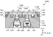
図1は、本実施形態における家庭用ゲーム装置1200の構成例を説明するための図である。同図に示すように、家庭用ゲーム装置1200は、ゲーム装置本体1201と、メインゲームコントローラ1230と、サブコントローラ1270と、ビデオモニタ1220とを備える。そして本実施形態では、メインゲームコントローラ1230とサブコントローラ1270のうち少なくとも一方を、ゲームコントローラケース100の中に入れ、ゲームコントローラケース100を仮想楽器の太鼓(本実施形態では和太鼓)と見立てて、付属する棒状体であるバチ棒101で叩き操作してゲームプレイする。[Description of system configuration]
FIG. 1 is a diagram for explaining a configuration example of a
ゲーム装置本体1201は、例えばCPUや画像処理用LSI、ICメモリ等が実装された制御ユニット1210と、光学ディスク1202やメモリカード1204といった情報記憶媒体の読み取り装置1206,1208とを備える。そして、家庭用ゲーム装置1200は、光学ディスク1202やメモリカード1204からゲームプログラム及び各種設定データを読み出し、メインゲームコントローラ1230やサブコントローラ1270を収容したゲームコントローラケース100へ為された操作入力に基づいて制御ユニット1210が各種のゲーム演算を実行して音楽ゲームを実行する。 The game apparatus
制御ユニット1210は、CPU(Central Processing Unit)やGPU(Graphics Processing Unit)及びDSP(Digital Signal Processor)などの各種マイクロプロセッサ、ASIC(Application Specific Integrated Circuit)、ICメモリなどの電気電子機器を備え家庭用ゲーム装置1200の各部を制御する。
また、制御ユニット1210は、インターネットやLAN(Local Area Network)、WAN(Wide Area Network)と言った通信回線1と有線又は無線接続し、外部装置との間でデータ通信を実現する通信装置1212を備える。また、近距離無線通信モジュール1214を備え、近距離無線を介して複数のメインゲームコントローラ1230との間でデータの送受信を実現する。近距離無線の形式としては、例えばBluetooth(登録商標)やUWB(超広帯域無線)、無線LANなどが適宜適用可能である。The
In addition, the
そして、制御ユニット1210は、メインゲームコントローラ1230から受信した操作入力信号に基づいてゲーム画面やゲーム音を生成してビデオゲームを実行する。生成されたゲーム画面やゲーム音に基づく映像信号や音信号は、ケーブル1209で接続されたビデオモニタ1220(ディスプレイモニタ)に出力される。ビデオモニタ1220には、フラットパネルディスプレイといった画像を表示する画像表示装置1222と、音声を出力するスピーカ1224とが備えられており、プレーヤは画像表示装置1222に映し出されるゲーム画面を見ながら、スピーカ1224から放音されるゲーム音を聞きつつゲームをプレイする。 Then, the
[ゲームの説明]
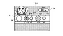
図2は、本実施形態におけるゲーム画面の例を示す図である。本実施形態における音楽ゲームは、ゲームコントローラケース100を和太鼓に見立ててゲーム画面に表示される楽譜に合わせて、太鼓の皮面に相当する上面(表情が描かれた面)や、上面外周角部又は側面をバチ棒101で叩き、仮想の和太鼓演奏を楽しむビデオゲームである。[Game description]
FIG. 2 is a diagram illustrating an example of a game screen in the present embodiment. In the music game according to the present embodiment, the upper surface corresponding to the surface of the drum (the surface on which the expression is drawn) or the outer peripheral angle of the upper surface corresponding to the score displayed on the game screen with the
同図に示すように、ビデオモニタ1220の画面表示装置1222には、背景上に楽譜表示部50と得点表示部52とが合成されたゲーム画面W2が表示される。楽譜表示部50の左部にはタイミングガイド53が固定表示されており、時間経過とともにタイミングガイド53に向かって楽譜表示部50の右端から左方向に様々な種類の音符マーク54a,54b,54cが次々に流れるように表示される。 As shown in the figure, the
音符マーク54a,54b,54cは、それぞれ異なる表示形態(色・形・明滅・大きさ・透明度などの形態を含む。)を有し、表示形態の種類毎に異なる音が対応づけられている。本実施形態では和太鼓の演奏をモチーフとしているので、音符マーク54aには「ドン(太鼓の皮面を叩いた音に相当)」、音符マーク54bには「カツ(太鼓の胴材の角を叩いた音に相当)」、音符マーク54cには太鼓の皮面を強く叩いた音に相当する「DON(ドンを大音量としたもの)」と言った具合に音の対応づけがなされている。 The note marks 54a, 54b, and 54c have different display forms (including forms such as color, shape, blinking, size, and transparency), and different sounds are associated with the types of display forms. In this embodiment, the performance of a Japanese drum is used as a motif, so that the
従って、プレーヤはゲーム画面W2を見ながら、音符マーク54a,54b,54cがタイミングガイド53内に入ったタイミングを狙ってその音符マーク54の種類に対応するゲームコントローラケース100の操作位置(操作面)を叩き操作する。すると、ビデオモニタ1220のスピーカ1224から操作入力の種類に対応付けられた音が放音される。タイミングと音の種類を正しく合わせて操作入力すると得点が得られるとともにゲームプレイを通して一曲が正しく演奏される格好となる。 Therefore, the player looks at the game screen W2 and aims at the timing at which the note marks 54a, 54b, 54c enter the
尚、同図はプレーヤが一人でプレイする場合のゲーム画面例であるが、二人同時にプレイする場合には、楽譜表示部50と得点表示部52とを各プレーヤ別に用意し、例えば上下2段にレイアウトして表示する。 This figure shows an example of a game screen when a player plays alone. However, when two players play simultaneously, a
次に、メインゲームコントローラ1230、サブコントローラ1270及びゲームコントローラケース100の詳細な構成について説明する。 Next, detailed configurations of the
[ゲームコントローラの説明]
図3は、本実施形態において用いられるメインゲームコントローラ1230の構成例を示す外観図であって、(a)正面図、(b)正面向かって右から見た右側面図、(c)後側面図に相当する。尚、以下のメインゲームコントローラ1230の向きを説明する際は、図3(a)における上、下、左、右をそれぞれ前方、後方、左、右とし、図3(b)における左、右をそれぞれ正面、背面という。また、本明細書中でメインゲームコントローラ1230の全長とは、図3における長手方向の長さであり、全幅とは図3(a)における横幅、全高とは図3(b)における横幅を意味する。[Description of game controller]
FIG. 3 is an external view showing a configuration example of the
同図に示すように、メインゲームコントローラ1230は面取りされた略四角断面を有する棒状を成しており、単独で使用する場合にはプレーヤは棒を握る要領でその後方部分を片手把持し操作することができる。 As shown in the figure, the
メインゲームコントローラ1230は、内蔵するコントローラ制御ユニット1260を中心に、各種入力デバイス及び出力デバイスを、例えばIIC(Inter-Integrated Circuit)バスなどによって実現されるローカルバス回路によって接続しており、コントローラ制御ユニット1260によって各デバイス間の入出力を制御する。 The
具体的には、スイッチに代表される可動式の入力デバイスとしては、正面側(操作面側)に十字状の四隅を押下することで上下左右の方向を個別に入力することのできる方向入力キー1232、Aボタン1234、第1〜第3サブボタン1236、第1ボタン1238と第2ボタン1240を備える。また、背面側の中央よりやや前方側には可動式の入力デバイスであるトリガー1242を備える。 Specifically, as a movable input device typified by a switch, direction input keys that can individually input up, down, left, and right directions by pressing down the four cross-shaped corners on the front side (operation surface side) 1232, an
また、その他の入力デバイスとしては、メインゲームコントローラ1230の動きや傾きを検出するための加速度センサ1244と、撮像素子1246とを備える。
加速度センサ1244はメインゲームコントローラ1230の長手先端方向(図3(a)の上方向:前方方向)をZm軸のプラス方向、正面向かって右方向(図3(a)の右方向)をXm軸のプラス方向、正面向かって手前方向(図3(b)の左方向)をYm軸のプラス方向とする直交3軸方向の各加速度を検出し、検出した加速度に応じた電圧等の検出信号をコントローラ制御ユニット1260に出力する。
撮像素子1246は、CCDセンサやCMOSセンサによって実現され、メインゲームコントローラ1230の先端に設けられて長手方向前方(先端方向:前方方向)の様子を撮影し、画像信号をコントローラ制御ユニット1260に出力する。本実施形態では、公知のゲーム装置と同様に、撮像素子1246で撮影された画像信号に基づいて、例えばゲーム画面内にポインタを表示させることができる。Other input devices include an
In the
The
また、本実施形態におけるメインゲームコントローラ1230は、出力デバイスとしてバイブレータ1250と、スピーカ1252と、を備える。
バイブレータ1250は、コントローラ制御ユニット1260から出力された振動制御信号に従って振動を発生させ、メインゲームコントローラ1230を把持するプレーヤの手に振動を感じさせる。
スピーカ1252は、コントローラ制御ユニット1260から出力された音出力信号に従って音を発生させ、操作面側に放音する。Further, the
The
コントローラ制御ユニット1260は、例えば、CPUやローカルバス回路におけるデータ通信を制御するバスコントローラICなどの各種マイクロチップやICメモリなどの電子部品、ゲーム装置本体1201の近距離無線通信モジュール1214と無線通信を実現する近距離無線通信モジュール1262などを実装する。 The
そして、コントローラ制御ユニット1260は、ローカルバス回路を介して各種入力デバイスから送信された信号に基づいて操作入力信号を生成し、生成した操作入力信号を近距離無線通信モジュール1262でゲーム装置本体1201へ送信する。また、近距離無線通信モジュール1262によって、ゲーム装置本体1201から送出された出力信号を受信した場合には、受信した出力信号に対応づけられている出力デバイスへ制御信号を生成・送出する。
尚、コントローラ制御ユニット1260及び各部が必要とする電力は、メインゲームコントローラ1230の背面側に凹設されたバッテリー室内に内蔵されたバッテリー1264から供給される。Then, the
The electric power required by the
また、本実施形態におけるメインゲームコントローラ1230は、その後端面に、操作入力デバイス及び出力デバイスを繋ぐ通信ケーブルを着脱自在に接続するための拡張端子1266を備える。
拡張端子1266は、コントローラ制御ユニット1260に設けられたローカルバス回路を外部に拡張するための端子である。本実施形態におけるローカルバスは、例えばIIC(Inter-Integrated Circuit)バス規格によって実現され、所定形状のコネクタを活線挿抜に接続することができるとともに、拡張端子1266に含まれる接続ピンの電圧を検知することで挿抜に伴うコネクタやデバイスの接続検出ができる。In addition, the
The
図4は、本実施形態におけるサブコントローラ1270の構成例を示す外観図であって、(a)右側面図、(b)右斜め下から見上げた斜視下面図に相当する。尚、以下のサブコントローラ1270の向きを説明する際は、図4(a)における上、下、右、左をそれぞれ上面、下面、前側、後側と言う。また、本明細書中でサブコントローラ1270の全長とは、図4における長手方向の長さである。 FIG. 4 is an external view showing a configuration example of the sub-controller 1270 in the present embodiment, and corresponds to (a) a right side view and (b) a perspective bottom view looking up from an obliquely lower right side. In the following description of the orientation of the
サブコントローラ1270は、メインゲームコントローラ1230(親コントローラ)に機能追加のために接続される子コントローラである。サブコントローラ1270は、可動式の入力デバイスとしてジョイスティック1272と、プッシュスイッチであるCボタン1274及びZボタン1276とを備え、また非可動式の入力デバイスとして加速度センサ1277を備える。加速度センサ1277は、前方をZs軸プラス、右方向(図4(a)で言うところの図面の手前側)をXs軸プラス、上面方向をYs軸プラスとする直交3軸の加速度を検出することのできるセンサである。 The sub-controller 1270 is a child controller connected to the main game controller 1230 (parent controller) for function addition. The sub-controller 1270 includes a
また、サブコントローラ1270はメインゲームコントローラ1230の拡張端子1266に接続される信号ケーブル1278を備える。信号ケーブル1278を拡張端子1266に接続すると、メインゲームコントローラ1230から電力の供給を受け、ジョイスティック1272やCボタン1274、Zボタン1276へ為された操作入力に応じた操作入力信号や、加速度センサ1277の加速度検出信号をメインゲームコントローラ1230へ出力することができる。そして、メインゲームコントローラ1230のコントローラ制御ユニット1260は、サブコントローラ1270から入力された操作入力信号を、ゲーム装置本体1201へ無線送信する。 The
また、サブコントローラ1270は、上部外殻1270aと、下部外殻1270bの2ピースの外殻を有し、下部外殻1270bには、下部外殻1270bの底面(下面)より正面(上面)方向へ向けて凹設された円筒状の有底凹部1270cが設けられている。この有底凹部1270cの底部にはビス取り付け穴が設けられており、ビス1270dによって上部外殻1270aと下部外殻1270bとが連結される。本実施形態では、有底凹部1270cは、長手方向に沿って前後2箇所に設けられ、その深さは同コントローラの厚さの半分以上に及ぶように設定されている。 Further, the sub-controller 1270 has a two-piece outer shell of an upper
[ゲームコントローラケースの構成の説明]
図5は、本実施形態におけるゲームコントローラケース100の構成例を示す分解斜視外観図である。ゲームコントローラケース100は、メインゲームコントローラ1230及びサブコントローラ1270の少なくとも一方をケース本体102に収納し、更にそのケース本体102の全外周を覆うカバー190内に収納して形成される。[Description of game controller case configuration]
FIG. 5 is an exploded perspective external view showing a configuration example of the
ゲームコントローラケース100は全体として平たい円柱状を成した和太鼓をイメージした外形を有する。その上面は和太鼓の皮面に相当し、カバー190の上面部分には目や口といったキャラクタの表情要素104が頭頂方向をケース前方に向けた姿勢でプリントされている。カバー190の内寸は、メインゲームコントローラ1230を収納した状態で運搬しても収容されているケース本体102の位置ズレが起きない程度に密着するように設計されている。 The
ケース本体102は、メインゲームコントローラ1230等を所定の相対姿勢で固定・収容するコントローラ収容部110と、プッシャープレート130とを備える。 The case
プッシャープレート130は、外縁に幅1cm程度の環状枠部112を残してコントローラ収容部110の上面に設けられた円形凹部114内に遊嵌され、所定ストローク範囲内で上下方向に可動可能に弾性支持されている。プッシャープレート130は和太鼓の皮面に相当し、環状枠部112が和太鼓の胴部の角部に相当する。プレイする際にはケース本体102はカバー190の中に隠れることになるが、プレーヤが太鼓の皮面を叩く「ドン」の音を入力したいと望む場合には上面のプッシャープレート130の中央部を狙うつもりで上方から叩き操作し、胴部の角を叩く「カツ」の音を入力したいと望む場合には、上面外縁の環状枠部112を狙うつもりで斜め上から叩き操作するといった具合に、平置きの和太鼓を演奏する要領で叩き操作する。 The
また、プッシャープレート130の上面には、ケース本体102の前後方向を示す方向指標131がプリントや型押し、彫り込み等によって形成されている。本実施形ではカバー190の上面にプリントされる表情要素104と同様のものが設けられており、ケース本体102をカバー190に入れる際の位置合わせの助けとなる。 A
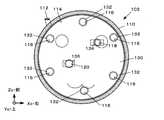
図6は、本実施形態におけるケース本体102の構成例を示す上面図である。図7は同下面図、図8〜図10は図7における各縦断面図に相当する。また、図11は本実施形態におけるプッシャープレート130の構成例を示す図であって、(a)上面図、(b)D−D断面図、(c)E−E断面図、(d)後方より見た側面図、に当る。 FIG. 6 is a top view illustrating a configuration example of the case
図6,図8〜図10に示すように、コントローラ収容部110は、PVDF(フッ化ビニリデン樹脂)フォームやポリエチレンフォーム、ゴムスポンジなどの硬質発砲樹脂で形成された中実体であり、メインゲームコントローラ1230及びサブコントローラ1270を前後直径方向に沿って寝かせた姿勢で収容することのできる平たい円柱形状の外形を有する。 As shown in FIG. 6 and FIG. 8 to FIG. 10, the
その上面には、外縁に幅1cm程度の環状枠部112を残して円形凹部114が凹設されている。円形凹部114の深さは、プッシャープレート130が上下にストロークしても底面と干渉しない程度に十分な値が設定されている。 A
また、円形凹部114の底面には、有底のガイド穴116が複数箇所設けられている。ガイド穴116は、プッシャープレート130の下面に設けられたガイドピラー132とピストン/シリンダの関係でスライド自在に遊嵌し、プッシャープレート130の上下運動のストロークをガイドする。同図の例では、プッシャープレート130とコントローラ収容部110とが所定の相対姿勢でのみ組み立てされるように非対称な位置に6つのガイド穴116が設けられている。
尚、ガイド穴116の数や配置位置は、プッシャープレート130が傾斜することなく、ストロークできる限りにおいて適宜設定することができる。また、同図では図示していないが、滑りを良くするためにガイド穴116にテフロン(登録商標)チューブなど摩擦抵抗を低減するインナーが嵌着されているとより好ましい。In addition, a plurality of bottomed guide holes 116 are provided on the bottom surface of the
The number and arrangement positions of the guide holes 116 can be appropriately set as long as the stroke is possible without the
ガイドピラー132の下端には、弾性材として蛇腹状又はカップ型のシリコンスプリング133が接着又は嵌め込みによって装着されている(図11参照)。
シリコンスプリング133は、プッシャープレート130の上面をバチ棒101で叩き操作する外力によって弾性変形し、メインゲームコントローラ1230やサブコントローラ1270の所定スイッチ(本実施形態ではトリガー1242、Zボタン1276)を押し込み操作する程度で、且つスイッチ側のストローク許容範囲内でストロークするように設定されている。また、シリコンスプリング133の下端はガイド穴116の底面に固定されている。つまり、プッシャープレート130がコントローラ収容部110に組み付けられると、両者はシリコンスプリング133を介して連結されることとなり、組み立て後のプッシャープレート130の脱落を防止する。A bellows-like or cup-shaped
The
更に、本実施形態では、ガイドピラー132の突寸と、ガイド穴116の深さと、シリコンスプリング133の自由状態における長さ及び最も弾性変形した状態の最小の長さは次のように設計されている。すなわち、自由状態(叩打されていない状態)では、プッシャープレート130の上面が環状枠部112の上面よりも1〜2mm程度下方に位置するように設計されている。また、プッシャープレート130が叩打操作によって押し込まれた場合には、プッシャープレート130の下面の最大到達位置が円形凹部114の底面に当らない位置となるように設計されている。
このようにプッシャープレート130の上面位置を環状枠部112の位置より僅かに下げて設定することによって、環状枠部112がプッシャープレート130の枠部として機能する。すなわち、プレーヤが和太鼓の胴部の角を叩き操作する際にバチ棒101が意図せずにプッシャープレート130の上面に当ってしまって、誤入力となることを防ぐ効果を生む。Further, in the present embodiment, the protrusion size of the
In this way, by setting the upper surface position of the
また、図6、図8〜図10に示すように、コントローラ収容部110の円形凹部114には、円形の中心を挟んでおおむね対称な位置にプッシャープレート130の下面に突設されたプッシュロッド134、136を遊挿するプッシュロッド挿通孔118、120を備える。 Further, as shown in FIGS. 6 and 8 to 10, a
プッシュロッド134,136の各先端は、プッシュロッド挿通孔118,120を抜けて、コントローラ収容部110の下面に開口するように凹設されたメインゲームコントローラ収容凹部140、サブコントローラ収容凹部142に達する。そして、各先端にはプッシュヘッド135,137が接着などによって装着される。 The distal ends of the
プッシュヘッド135,137は、滑り止め効果のあるシリコンや合成ゴムの中実体で、図10,図11に示すように、下面側には嵌着凹部135a,137aを備える。嵌着凹部135a,137aは、それぞれメインゲームコントローラ収容凹部140に収容・固定されたメインゲームコントローラ1230のトリガー1244、サブコントローラ収容凹部142に収容・固定されたサブコントローラ1270のZボタン1276にそれぞれ被さって嵌着する形状を成している。
また、本実施形態ではプッシュヘッド135,137の横幅はプッシュロッド挿通孔118,120の径よりも大きく設定されており、その上端がメインゲームコントローラ収容凹部140の天井やサブコントローラ収容凹部142の天井に当接することでプッシャープレート130の上方への移動を規制し、実質的なプッシュロッド134,136の抜け止めとして機能する。The push heads 135 and 137 are solid bodies of silicone or synthetic rubber having an anti-slip effect, and as shown in FIGS. 10 and 11, the push heads 135 and 137 include
In this embodiment, the lateral width of the push heads 135 and 137 is set to be larger than the diameter of the push rod insertion holes 118 and 120, and the upper ends of the push heads 135 and 137 are the ceiling of the main game
図7〜図10に示すように、メインゲームコントローラ収容凹部140は、メインゲームコントローラ1230の前後をコントローラ収容部110(つまりゲームコントローラケース100)の前後方向に合わせてメインゲームコントローラ1230を寝かせ、且つメインゲームコントローラ1230の上下をコントローラ収容部110の上下とは逆さまの姿勢で収容することのできる前後に長い空間である。 As shown in FIGS. 7 to 10, the main game
メインゲームコントローラ収容凹部140の内面には、左右及び前後の各対向位置に対を成した弾性片146が設けられている。当該収容凹部にメインゲームコントローラ1230を装着すべくメインゲームコントローラ収容凹部140の底面に突き当たるまで押し込むと、これら弾性片146は弾性変形し、メインゲームコントローラ1230の左右方向及び前後方向に密着してメインゲームコントローラ1230を位置決めし固定する。勿論、コントローラ収容部110の材質自体に適当な弾性が備わっている場合には、弾性片146を省略し、メインゲームコントローラ収容凹部140全体が弾性片146と同様に機能するようにしても良いのは勿論である。 On the inner surface of the main game
また、メインゲームコントローラ収容凹部140の前端壁にはコントローラ収容部110の外周まで貫通する撮影窓148が開口し、メインゲームコントローラ収容凹部の後端壁には、サブコントローラ1270の信号ケーブル1278の端子を挿通できるケーブル挿通孔150が設けられている(図8参照)。撮影窓148は、当該収容凹部に収容されたメインゲームコントローラ1230の撮像素子1246の前方撮影範囲を確保する。 In addition, a shooting
また、メインゲームコントローラ収容凹部140の天井部分であって、メインゲームコントローラ1230を収容した際にトリガー1242が位置する領域には、トリガー1242が自由状態で収容されるようにトリガー収容空間141が凹設されており、プッシュヘッド135は当該収容空間に収まる Further, the
もう一方の収容凹部であるサブコントローラ収容凹部142は、サブコントローラ1270の前後をコントローラ収容部110の前後とは逆方向に合わせて寝かせ、且つサブコントローラ1270の上下がコントローラ収容部110の上下とは逆さまの姿勢で収容することのできる前後に長い空間であり、メインゲームコントローラ収容凹部140とほぼ平行に併設されている。 The
サブコントローラ収容凹部142の内面には、左右の各対向位置に対を成した弾性片146が設けられているとともに、その底面2カ所に嵌合突起152が突設されている。嵌合突起152は、サブコントローラ1270の有底凹部1270cに嵌合する形状を有する。当該収容凹部にサブコントローラ1270を装着するには、サブコントローラ1270の有底凹部1270cを嵌合突起152に嵌めるようにしながらサブコントローラ収容凹部142の底面に突き当たるまで押し込むと、弾性片146は弾性変形してサブコントローラ1270を位置決めし固定するとともに、嵌合突起152によっても位置決めと固定が成される。 On the inner surface of the
また、サブコントローラ収容部142の前端壁には、コントローラ収容部110の外周に達するケーブル挿通孔154が貫通されており、同収容凹部に収容されたサブコントローラ1270の信号ケーブル1278を外部に引き出すことができる(図9参照)。
また、サブコントローラ収容凹部142の天井部分であって、サブコントローラ1270を収容した際にZボタン1276が位置する領域には、Zボタン1276が自由状態で収容されるようにZボタン収容空間143が凹設されており、プッシュヘッド137は当該収容空間に収まるFurther, a
Further, in the area of the ceiling of the sub
そして、メインゲームコントローラ収容凹部140とサブコントローラ収容部142は、共に前後中程の位置にて指入れ孔144によって左右に貫かれており(図7参照)、見かけ上は一体の凹部を成している。指入れ孔144は、収容・固定されたメインゲームコントローラ1230やサブコントローラ1270を各収容凹部から取り外す際に各コントローラに指をかけるための空間である。 The main game controller
図12は、本実施形態におけるカバー190の構成例を示す図であって、(a)上面図、(b)F−F断面図、(c)下面図である。
カバー190は、布製カバーであり、その上面には目や口といったキャラクタの表情要素104がプリントされており、全体として和太鼓を擬人化したキャラクタとしての意匠を有する。表情要素104から判別される頭部方向がケースの前方となる。FIG. 12 is a diagram illustrating a configuration example of the
The
内寸はメインゲームコントローラ1230を収納した状態で運搬しても収容されているケース本体102の位置ズレが起きない程度に密着するように設定されている。カバー190を説明する際の方向は、ケース本体102を収納した状態のケース本体102の方向と同様である。 The inner dimensions are set so that the case
カバー190の側面下部には、外周沿いにジッパー192が設けられており開閉自在となっており、ジッパー192を空けてケース本体102を収容し、ジッパー192を閉じて収容完了する。カバー190の下面(背面)にはすべり止め194が貼設されており、テーブルや床面に置いて使用する場合の位置ズレを抑制する。 A
また、カバー190の前方側には、ケース本体102を収容した場合に撮影窓148、ケーブル挿通孔150、ケーブル挿通孔154を覆うであろう各位置に、それぞれ開口部195,196、197が設けられている。 Further, on the front side of the
また、カバー190の下面にはメインゲームコントローラ収容凹部140及びサブコントローラ収容部142の開口部を覆うであろう各位置に、それぞれ開口部198が設けられており、ゲームコントローラケース100を上下逆さまにすると、収容されているゲームコントローラケース100やサブコントローラ1270を外部から操作できるようになっている。これによって、メインゲームコントローラ1230やサブコントローラ1270をゲームコントローラケース100に収容したままでも、叩き操作以外のメニュー選択などの操作も可能になる。 In addition, an
[ゲームコントローラケースの使い方の説明]
ゲームコントローラケース100は、家庭用ゲーム装置1200の所有者を主な購買層と考えて、コントローラ収容部142に予めプッシャープレート130が組み付けられた状態で、カバー190、バチ棒101とセットで販売される。更に、ゲームプログラムを記憶した光学ディスク1202を同梱しても良い。[Description of how to use the game controller case]
The
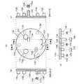
図13は、ケース本体102にメインゲームコントローラ1230及びサブコントローラ1270を収容した状態を示す組み立て図であって、(a)下面図、(b)G−G断面図、(c)H−H断面図、(d)J−J断面図に相当する。なお、断面として図示しているのはケース本体102のみであり、メインゲームコントローラ1230及びサブコントローラ1270については、断面として図示していない。
同図に示すように、プレーヤは先ず、メインゲームコントローラ1230とサブコントローラ1270のうち少なくとも一方を、コントローラ収容部142のメインゲームコントローラ収容凹部140又はサブコントローラ収容部142に嵌め込んで装着する。この状態で、プッシャープレート130のプッシュヘッド135は、トリガー1242に覆い被さり、プッシュヘッド137はZボタン1276に覆い被さる格好となる。
尚、サブコントローラ1270を装着する際には、信号ケーブル1278をケーブル挿通孔154に挿通させておく。FIG. 13 is an assembly diagram illustrating a state in which the
As shown in the figure, the player first fits and attaches at least one of the
When the
そして、ケース本体102にメインゲームコントローラ1230とサブコントローラ1270のうち少なくとも一方を収容したならば、プッシャープレート130の上面に設けられた方向指標131を頼りに前後方向を合わせてカバー190に収容しプレイ準備完了となる。 When at least one of the
二人同時プレイする場合には、例えば図14(a)に示すように、ゲームコントローラケース100−1,100−2を二つ用意して、一方にメインゲームコントローラ1230のみを収容し、他方にサブコントローラ1270を収容して、信号ケーブル1278を一方のゲームコントローラケース100の開口部196及びケーブル挿通孔150を挿通させて、収容されているメインゲームコントローラ1230の拡張端子1266に接続する構成を取ることができる。この場合、サブコントローラ1270への操作入力に係る情報は、メインゲームコントローラ1230によってゲーム装置本体1201へ送信される。勿論、ゲーム装置本体1201が個体識別可能なメインゲームコントローラ1230をプレーヤが複数台所有する場合には、例えば図14(b)に示すように、ゲームコントローラケース100を二つ用意して各々に一台ずつメインゲームコントローラ1230を収容して二人同時プレイするとしても良い。 When two players play simultaneously, for example, as shown in FIG. 14A, two game controller cases 100-1 and 100-2 are prepared, and only the
[操作入力種類の判定原理の説明]
図15及び図16は、本実施形態における操作入力例と入力種類の判定原理を説明するための図である。図15は太鼓の皮面を叩くのに相当するバチ棒101でゲームコントローラケース100の上面、つまりはプッシャープレート130を叩き操作する場合を示す。図16は太鼓の胴部の角の部分を叩く場合の代表としてゲームコントローラケース100の上面外周の角部、つまりは環状枠部112を斜め上から叩き操作する場合を示している。
尚、ここではメインゲームコントローラ1230とサブコントローラ1270との両方が収容されている状態を図示しているが何れか一方のみが収容されている形態でも良い。また、作用力などについてはサブコントローラ1270についてのみ図示して簡略化しているが、メインゲームコントローラ1230についても同様に作用する。[Description of operation input type judgment principle]
15 and 16 are diagrams for explaining an operation input example and an input type determination principle in the present embodiment. FIG. 15 shows a case where the upper surface of the
Here, a state in which both the
さて、ゲームコントローラケース100の上面を叩き操作する場合、図15(a)に示すように、その外力はプッシャープレート130が外力受面部として受けることになる。本実施形態ではシリコンスプリング133は、プッシャープレート130が当該叩き操作の外力によって収容されているメインゲームコントローラ1230やサブコントローラ1270のスイッチを「ON」するだけストロークする弾性特性を有するように設定されているので、プッシャープレート130は下方へ可動しプッシュロッド136がZボタン1276を押すことになる。 When the upper surface of the
やがてプッシャープレート130がフルストローク(full stroke)してシリコンスプリング133がそれ以上縮めなくなると、当該叩き操作の外力がシリコンスプリング133を介して伝達されてコントローラ収容部110が下方への外力を受ける。結果、収容・固定されているサブコントローラ1270も下方の外力を受けることとなり、内蔵する加速度センサ1277で下方への加速度が検出される。 When the
本実施形態におけるサブコントローラ1270のコントローラ収容部110への取り付け姿勢によれば、加速度センサ1277の検出座標軸(Xs,Ys,Zs)はケース本体102の座標軸(Xc,Yc,Zc)とは上下・前後・左右が逆さまとなる。よって、加速度センサ1277の各軸の加速度を時間微分して躍動を求めてその時間変化を観ると、図15(b)に示すようにYs軸方向への躍動jysにパルス状の変化が現れる。According to the mounting orientation of the sub-controller 1270 in the
一方、メインゲームコントローラ1230については、プッシャープレート130の下降運動に伴ってプッシュロッド134によってトリガー1242が押されて「ON」となる。そして、メインゲームコントローラ1230の加速度センサ1244の検出座標軸(Xm,Ym,Zm)はケース本体102の座標軸(Xc,Yc,Zc)とは上下・左右が逆さまとなるので、図15(c)に示すようにYm軸方向への躍動jymにパルス状の変化が現れる。On the other hand, with respect to the
従って、収容されているメインゲームコントローラ1230又はサブコントローラ1270の所定のスイッチ(メインゲームコントローラ1230であればトリガー1242。サブコントローラ1270であればZボタン1276。)が「ON」であれば、ゲームコントローラケース100の上面が叩き操作されたと判定することができる。勿論、メインゲームコントローラ1230又はサブコントローラ1270の所定のスイッチが「ON」で、且つ、ノイズとの識別が十分な所定の入力判定基準L1(躍動の絶対値と比較)を超える躍動jがYs軸又はYm軸にて検出された場合に、ゲームコントローラケース100の上面が叩き操作されたと判定することとしてもよい。 Therefore, if a predetermined switch of the stored
次に、ゲームコントローラケース100の上面外周の角部が叩き操作された場合、図16(a)に示すように、その外力は環状枠部112で受けることになる。プッシャープレート130はシリコンスプリング133で弾性支持されているので外力は受けず、プッシャープレート130が当該叩き操作の外力によって収容されているメインゲームコントローラ1230のトリガー1242や、サブコントローラ1270のZボタン1276は押されることなく「OFF」のままとなる。 Next, when the corner portion on the outer periphery of the upper surface of the
一方、当該叩き操作の外力は、コントローラ収容部110は斜め下向きに作用するので、図16の例では、サブコントローラ1270の加速度センサ1277は図16(b)に示すようにXs軸の躍動jxs及びYs軸方向への躍動jysの両方にパルス状の変化が現れる。
同様に、メインゲームコントローラ1230の加速度センサ1244では図16(c)に示すようにXm軸の躍動jxm及びYm軸方向の躍動jymの両方にパルス状の変化が現れる。On the other hand, the external force of the hitting operation acts diagonally downward in the
Similarly, pulse-like change in both the dynamicj ym of dynamicj xm and Ym-axis direction of the Xm axis, as shown in the
従って、収容されているメインゲームコントローラ1230又はサブコントローラ1270の所定のスイッチ(メインゲームコントローラ1230であればトリガー1242。サブコントローラ1270であればZボタン1276。)が「OFF」で、且つ所定の入力判定基準を超える躍動jが検出された場合、ゲームコントローラケース100の上面外周の角部が叩き操作されたと判定することができる。 Therefore, a predetermined switch of the stored
よって、スイッチのON/OFFを入力種類の判定条件に利用することで、加速度センサ1244,1277によって検出された加速度のみでは判定しにくい斜め方向からの叩き操作も確実に識別することが可能になる。 Therefore, by using ON / OFF of the switch as a determination condition for the input type, it is possible to reliably identify a hit operation from an oblique direction that is difficult to determine only by the acceleration detected by the
尚、上面外周の角部への叩き操作については叩き操作の方向、つまりは外周のどの相対位置で叩き操作を受けたかを識別することができる。
例えば、前/後方向から斜めに叩き操作された場合、換言すると時計で言うところの12時辺り又は6時辺りの上面外周の角部が叩かれた場合には、メインゲームコントローラ1230ではXm軸とZm軸方向の両方に躍動jが現れ、サブコントローラ1270ではXs軸とZs軸の両方に躍動jが現れる。Zm軸及びZs軸の躍動jの正/負によって前方/後方の判別もできる。As for the hit operation to the corner portion of the outer periphery of the upper surface, the direction of the hit operation, that is, the relative position on the outer periphery can be identified.
For example, when a slanting operation is performed diagonally from the front / rear direction, in other words, when the corner of the outer periphery of the top surface around 12 o'clock or 6 o'clock as hit by the watch is hit, the
また、前後方向に対して斜め45度の方向から上面外周の角部へ叩き操作された場合、換言すると時計で言うところの1〜2時、4〜5時、7〜8時、10〜11時の辺りで上面外周の角部が叩かれた場合には、メインゲームコントローラ1230ではXm・Ym・Zmの3軸において躍動jが現れ、サブコントローラ1270ではXs・Ys・Zsの3軸において躍動jが現れる。そして、躍動jの正/負の組み合わせによって、更に左右及び前後の斜め方向が判別できる。 In addition, when a hit operation is performed from 45 degrees oblique to the front-rear direction to the corner of the outer periphery of the upper surface, in other words, 1 to 2 o'clock, 4 to 5 o'clock, 7 to 8 o'clock, 10 to 11 When the corner of the top surface is hit around the time, the
従って、入力判定基準を超える躍動jが現れた軸方向の組み合わせ及びそのパルス状波形のピーク値の正/負によって、どの方向から上面外周の角部が叩き操作されたか、あるいは外周のどの相対位置で上面外周の角部への叩き操作を受けたかを判定することができる。よって、その分だけより多くの入力種類を識別することが可能になる。 Therefore, from which direction the corner of the outer periphery of the top surface is struck or which relative position of the outer periphery is determined by the combination of the axial direction in which the jump j exceeding the input criterion appears and the positive / negative of the peak value of the pulse waveform. It is possible to determine whether or not a hitting operation has been performed on the corners on the outer periphery of the upper surface. Therefore, it becomes possible to identify more input types by that amount.
[機能ブロックの説明]
次に、家庭用ゲーム装置1200の機能構成について説明する。
図17は、本実施形態における家庭用ゲーム装置1200の機能構成例を示す機能ブロック図である。家庭用ゲーム装置1200は、操作部400と、処理部200と、音出力部350と、画像表示部360と、通信部370と、記憶部500とを備える。尚、本実施形態では、操作部400はゲームコントローラケース100内に収容される。[Description of functional block]
Next, the functional configuration of the
FIG. 17 is a functional block diagram illustrating an example of a functional configuration of the
操作部400は、図1で言うところのメインゲームコントローラ1230(親コントローラ)、及びこれに信号ケーブル1278で接続されたサブコントローラ1270(子コントローラ)が該当し、ローカル制御部402、操作入力部410、出力部414、接続部416、通信部418を備える。 The
操作入力部410は、プッシュボタンや、レバー、タッチパッド、ダイヤル、キーボード、マウス、各種ポインタ、加速度センサ、傾斜センサ、ジャイロ、GPSなどの入力デバイスやセンサ類によって実現され、プレーヤによって為された各種の入力に応じてローカル制御部402に出力する。 The
本実施形態の操作入力部410は、可動部が操作されたことを検出する受動検出部411と、直交3軸の加速度を検出する加速度検出部412とを含む。
受動検出部411は、スイッチやレバー、ダイヤルなどによって実現される。本実施形態では、メインゲームコントローラ1230のトリガー1242やサブコントローラ1270のZボタン1276がこれに該当するが、コントローラ収容部100への収容レイアウトによっては他のボタンスイッチ(例えば、方向入力キー1232、Aボタン1234、Cボタン1274)やジョイスティック1272などとすることもできる。
加速度検出部412は、メインゲームコントローラ1230の加速度センサ1244、サブコントローラ1270の加速度センサ1277が該当する。The
The
The
出力部414は、バイブレータ、ライト、スピーカ、モータ、画像表示素子といった出力デバイスによって実現され、ローカル制御部402から送出された制御信号によってゲームの進行に応じた振動や光、音、動作、画像表示などの出力をする。図3の例ではバイブレータ1250及びスピーカ1252がこれに該当する。 The
接続部416は、例えばコネクタによって実現され、外部からの信号線を操作部400内の信号線と結線させるとともに、接続の有無を検知する仕組みを備える。図3の拡張端子1266及びメインゲームコントローラ1230のローカルバス回路がこれに該当する。 The
通信部418は、例えば、無線装置やLANアダプタなど通信回線1に接続するための機器によって実現され、外部装置との間で信号の送受を実現する。図3の近距離無線通信モジュール1262がこれに該当し、ゲーム装置本体1201の近距離無線通信モジュール1214(図1参照)に該当する通信部370との間でデータ通信を実現する。 The
ローカル制御部402は、例えばCPUやローカルバスにおけるデータ通信を司るバス制御ICといったマイクロプロセッサ、ASIC(特定用途向け集積回路)、ICメモリ、ローカルバスなどの電子部品・電子回路によって実現され、ICメモリ等で実現される記憶部(非図示)を作業領域として使用して操作部400の各機能部との間でデータの入出力を制御する。図3のコントローラ制御ユニット1260がこれに該当する。
そして、ローカル制御部402は、操作入力部410からの操作入力信号及び接続部416を介して付加された拡張操作部(本実施形態ではサブコントローラ1270に相当)から入力された信号に基づいて操作入力信号を生成し、通信部418を用いて通信部370へ操作入力信号を送信する。The
The
処理部200は、例えばCPUやGPUと言ったマイクロプロセッサ、ASIC(特定用途向け集積回路)、ICメモリなどの電子部品によって実現され、各機能部との間でデータの入出力を行うとともに所定のプログラムやデータ及び操作部400からの操作入力信号に基づいて各種の演算処理を実行して、家庭用ゲーム装置1200の動作を制御する。図1では、ゲーム装置本体1201に内蔵された制御ユニット1210が処理部200に該当する。そして、本実施形態における処理部200は、ゲーム演算部210と、音生成部250と、画像生成部260と、通信制御部270とを備える。 The
ゲーム演算部210は、ゲームの進行に係る処理を実行する。例えば、ゲーム画面の表示制御、操作入力のタイミング判定、得点の計算と言ったゲームの進行処理や結果判定処理などが実行対象に含まれる。そして、本実施形態におけるゲーム演算部210は、操作部400から送信された操作入力信号に基づいて操作入力種類を判定する操作入力種類判定部212を含む。 The
具体的には、操作入力種類判定部212は、現在の操作入力状況を判定する機能部であって、特に操作部400から受信した操作入力信号に含まれる受動検出部411のON/OFF、並びに加速度検出部412で検出された各検出軸方向の加速度に基づいて操作入力の種類を判定する。具体的には、加速度から躍動値を算出する。そして、所定の入力判定基準値を上回る躍動値に達した検出軸の種類とそのときの受動検出部411との組み合わせから入力種類を判定する。 Specifically, the operation input
また、本実施形態では更に躍動値の大きさに応じて更に操作入力の叩き操作の強度を判定する操作強度判定部214を含み、同じ入力判定基準値を上回る躍動値に達した検出軸の種類と受動検出部411との組み合わせであっても、検出した躍動値の大小に応じて異なる入力種類と判定することができる。 In addition, the present embodiment further includes an operation
音生成部250は、例えばデジタルシグナルプロセッサ(DSP)などのプロセッサやその制御プログラムなどの公知技術によって実現され、ゲーム演算部210による処理結果に基づいてゲームに係る効果音やBGM、各種操作音の音信号を生成し、音出力部350に出力する。 The
音出力部350は、音生成部250から入力される音信号に基づいて効果音やBGM等を音出力する装置によって実現される。図1ではビデオモニタ1220のスピーカ1224がこれに該当する。 The
画像生成部260は、例えば、GPUやデジタルシグナルプロセッサ(DSP)などのマイクロプロセッサ、その制御プログラム、フレームバッファ等の描画フレーム用ICメモリ等の公知技術によって実現される。そして、画像生成部260は、ゲーム演算部210による処理結果に基づいて所定のリフレッシュレート(例えば1/60秒)で1枚のゲーム画像信号を生成・出力し画像表示部360に出力する。 The
画像表示部360は、画像生成部260から入力される画像信号に基づいて各種ゲーム画像を表示する。画像表示部360は、例えば、フラットパネルディスプレイ、ブラウン管(CRT)、プロジェクター、ヘッドマウントディスプレイといった画像表示装置によって実現できる。図1ではビデオモニタ1220の画像表示装置1222がこれに該当する。 The
通信制御部270は、データ通信に係る処理を実行し、通信部370を介して外部装置との間でデータの送受を実現する。 The
通信部370は、外部装置との直接無線通信や通信回線1への接続によって通信を実現する。例えば、無線通信機、モデム、TA(ターミナルアダプタ)、有線用の通信ケーブルのジャックや制御回路等によって実現され、図1では通信装置1212、及び近距離無線通信モジュール1214がこれに該当する。 The
記憶部500は、予め定義されたプログラムやデータを記憶するとともに、処理部200の作業領域として用いられ、処理部200が各種プログラムに従って実行した演算結果等を一時的に記憶する。この機能は、例えばRAMやROM、EEPROMなどのICメモリ、ハードディスク等の磁気ディスク、CD−ROMやDVD―RAM、MOなどの光学ディスクによって実現される。 The
本実施形態における記憶部500は、処理部200にゲーム装置1200を統合的に制御させるための諸機能を実現するためのシステムプログラム501や、ゲームを実行させるために必要なゲームプログラム502並びに各種データ等を記憶する。処理部200がゲームプログラム502を読み出して実行することによって、処理部200にゲーム演算部210としての機能を実現させることができる。 The
また、記憶部500には、予め用意されるデータとして画面背景データ510と、楽譜データ512と、音TBLデータ514とを記憶している。
画面背景データ510は、ゲーム画面の背景を表示するためのデータである。例えば、静止画のデータでも良いし、3DCGで画像を表示する場合には、モデルデータやモデルに適用するテクスチャデータ、モーションデータ、仮想カメラの撮影位置や視線方向などの設定データと言った情報を含むとしても良い。Further, the
The
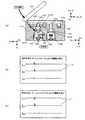
楽譜データ512は、譜面の画面表示開始からの時間経過とそのとき入力されるべき音種類が定義されている。例えば図18に示すように、時間経過512aと、入力されるべき入力種類に相当する音種類512bと、対応する音符マーク512cとが対応づけて格納されている。 The
音TBL(テーブル)データ514は、例えば図19に示すように、受動検出部411による受動検出有無516(プッシュスイッチならON/OFF)と躍動条件518との組み合わせを一の入力種類として、音種類520と、その音源データ522と、音量524とが対応づけて格納されている。
同図の例では、受動検出部411で受動検出され(プッシュスイッチならON)、且つ躍動jym又はjysが入力判定基準L1以上だが所定の強度判定基準未満の組み合わせでは、太鼓の皮を標準の力で叩き操作したのに相当する第1の操作入力種類と判定し、「ドン(太鼓の皮を叩いたときの音)」が選択され、標準音量で再生されることとなる。尚、所定の強度判定基準は、入力判定基準L1より大きい値である。
一方、受動検出部411で受動検出され、且つ躍動jym又はjysが入力判定基準L1以上であり更に躍動が強度判定基準以上である場合には、同じく「ドン」が選択されるが、標準より大きな音量で再生されることとなる。For example, as shown in FIG. 19, the sound TBL (table)
In the example shown in the figure, the drum skin is standard for a combination in which passive detection is performed by the passive detection unit 411 (ON if the push switch is used) and the dynamic jym or jys is greater than or equal to the input criterionC1 but less than a predetermined strength criterion. It is determined that the first operation input type is equivalent to the tapping operation with the power of, and “Don (sound when the drum skin is struck)” is selected and reproduced at the standard volume. The predetermined strength determination criterion is a value larger than the input determination criterion L1.
On the other hand, when passive detection is performed by the
尚、音TBLデータ514の設定内容はこれに限らず、受動検出の有無と、入力判定基準以上の躍動jが検出された検出軸の種類(検出軸の単独及び複数検出軸の組み合わせを含む)と、検出された躍動の大きさの組み合わせに応じて、更に多くの入力種類を設定し、それぞれに異なる音種類や音量を設定することもできる。 Note that the setting content of the
[処理の流れの説明]
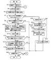
図20は、本実施形態における処理の流れを説明するためのフローチャートである。ここで説明する一連の処理は、処理部200がシステムプログラム501及びゲームプログラム502を読み出して実行することによって実現される。[Description of process flow]
FIG. 20 is a flowchart for explaining the flow of processing in the present embodiment. A series of processing described here is realized by the
同図に示すように、処理部200は、先ず楽譜データ512を読み出し(ステップS2)、音符マーク54a,54b,54cの流れるゲーム画面W2を表示制御する(ステップS4;図2参照)。 As shown in the figure, the
次に、加速度センサ1244及び加速度センサ1277で検出された3軸の加速度を微分することにより各軸の躍動値を算出する(ステップS6)。
そして、算出した3つの躍動のうち少なくとも何れか一つの躍動の大きさが、所定の入力判定基準値L1を超えるか否かによって叩き操作入力の有無を判定する(ステップS8)。入力判定基準L1を超える躍動が検出された場合(ステップS8のYES)、処理部200は叩き操作入力が有ったと判断し、音TBLデータ514を参照して、受動検出部411からの検出信号の有無、及び入力判定基準を超えるスパイク状の躍動の現れた検出軸種類、躍動の大きさに基づいて入力種類(本実施形態では音種類520と同意)を判定する(ステップS10)。Next, the jump value of each axis is calculated by differentiating the triaxial acceleration detected by the
Then, the presence / absence of a hitting operation input is determined based on whether or not the magnitude of at least one of the three calculated jumps exceeds a predetermined input determination reference value L1 (step S8). If a jump exceeding the input criterion L1 is detected (YES in step S8), the
次いで、処理部200は判定された入力種類に対応する音源データ522を読み出し、音量524の設定に従ってこれを再生し、音出力部350から放音させる(ステップS12)。結果、プレーヤがゲームコントローラケース100の上面を叩けば「ドン」の音がスピーカ1224から放音され、ゲームコントローラケース100の上面外周の角部や胴部を叩けば「カツ」の音が放音されるようになり、擬似的な和太鼓演奏が実現する。 Next, the
音出力処理を実行したならば、処理部200は叩き操作の有ったタイミングにおいてゲーム画面のタイミングガイド53の領域内に音符マーク54が入っているか否かを判定する(ステップS14)。具体的には、楽譜データ512を参照して、該操作入力の有ったタイミングの前後基準範囲以内に音種類512bの定義が有るか否かを判定し、定義が有ればタイミングガイド53の領域内に音符マーク54が入っていると判定する。 If the sound output process is executed, the
そして、タイミングガイド53の領域内に音符マーク54が入っている場合には(ステップS14のYES)、処理部200はタイミングガイド53の領域に入った音符マークに対応する音種類と、操作入力に基づき特定された音種類が合致すれば(ステップS16のYES)、得点を加算して合計得点をゲーム画面に表示制御する(ステップS18)。 When the note mark 54 is in the
そして、処理部200は一曲分の楽譜表示が終了していなければステップS4に戻り(ステップS50のNO)、一曲分の楽譜表示が終了したならば(ステップS50のYES)、一連の処理を終了してゲームを終了させる。 If the musical score display for one song has not been completed, the
よって、本実施形態によれば、メインゲームコントローラ1230やサブコントローラ1270をゲームコントローラケース100に収容して使用することで、太鼓演奏のように叩いて操作入力したとしてもメインゲームコントローラ1230やサブコントローラ1270を直接叩かないのでコントローラの損傷や故障を防ぐことができる。 Therefore, according to this embodiment, the
また、ゲームコントローラケース100による衝撃の適当な緩衝効果によって叩き操作に伴う衝撃の低次成分の振動のみがメインゲームコントローラ1230に伝達され、不必要なノイズと叩き操作入力に伴うパルス状の加速度変化とを容易に分離することができるので、操作入力の検出精度を高めることができる。 Further, only the vibration of the low-order component of the impact caused by the hitting operation is transmitted to the
また、本実施形態では所定受動部の受動検出の有無と、入力判定基準以上の躍動が検出された加速度検出軸の種類とに基づいて操作入力の種類を判定できる。従って、加速度のみで入力種類を判定する場合に比べて誤判定されにくい。特に、和太鼓の仮想演奏のように、上方からの第1の叩き操作と、斜め上方からの第2叩き操作のようにそもそも運動方向が類似している操作入力を用いるケースでは、プレーヤの叩き加減によって誤判定される可能性が高いが、本発明を適用すれば高い判定精度を実現できる。 Further, in the present embodiment, the type of operation input can be determined based on whether or not the predetermined passive portion is passively detected and the type of acceleration detection axis in which a sway that exceeds the input determination criterion is detected. Therefore, it is less likely to be erroneously determined than when the input type is determined only by acceleration. In particular, in the case of using an operation input whose movement direction is similar in the first place, such as the first hit operation from the upper side and the second hit operation from the diagonally upper side as in the virtual performance of the Japanese drum, the player hits it. Although there is a high possibility of erroneous determination due to adjustment, high determination accuracy can be realized by applying the present invention.
また、メインゲームコントローラ1230やサブコントローラ1270は、上下逆さまでゲームコントローラケース100に収容されている。しかも、これらを収容するメインゲームコントローラ収容凹部140及びサブコントローラ収容凹部142は同ケースの下面側に開口しており、スイッチ等を外部から操作できるようになっている。よって、ゲームコントローラケース100をひっくり返せば、コントローラを収容したままでもゲーム開始前のメニュー操作などが可能になるので利便性が高い。 The
〔第2実施形態〕
次に、本発明を適用した第2実施形態について説明する。本実施形態は基本的に第1実施形態と同様の構成を有するが、(1)メインゲームコントローラ1230とサブコントローラ1270との両方を収容することを前提とし、プッシャープレート130の左右で異なる入力が可能である点、(2)上面外周の角部にノッカー164を備える点において異なる。尚、第1実施形態と同様の構成要素については同じ符号を付与して説明は省略する。[Second Embodiment]
Next, a second embodiment to which the present invention is applied will be described. This embodiment basically has the same configuration as that of the first embodiment, but (1) on the premise that both the
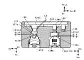
図21及び図22は、本実施形態におけるケース本体102Bの構成例を示す上面図と、縦断面図(図13のJ−J断面図に相当)である。
また、図23はノッカー164に第1実施形態で言うところのケース本体102Bの上面外周の角部への斜め叩き操作が行われた状態を示す拡大断面図である。21 and 22 are a top view and a longitudinal sectional view (corresponding to a JJ sectional view of FIG. 13) showing a configuration example of the case
FIG. 23 is an enlarged cross-sectional view showing a state in which the
図21及び図22に示すように、ケース本体102Bは、第1実施形態の円形凹部114に代えて上面視八角形の上面凹部114Bを有する。勿論、本実施形態における環状枠部112Bも上面視八角形を成す。
そして、上面凹部114Bに弾性支持されるプッシャープレート130Bは、右半体プレート130Rと左半体プレート130Lとで一の上面視八角形を成すように構成され、それぞれ独立して弾性支持されている。つまり、ゲームコントローラケース100の左右でそれぞれ異なる入力場所として利用することができる。
従って、音TBLデータ514の受動検出有無516をトリガー1242とZボタン1276との2種類に分け、更に躍動条件518を検出軸としてメインゲームコントローラ1230の加速度センサ1244の座標系(Xm,Ym,Zm)と、サブコントローラ1270の加速度センサ1277の座標系(Xs,YS,Zs)とで分けることで、第1実施形態よりも更に多くの入力種類を設定することができる。As shown in FIGS. 21 and 22, the case
The
Therefore, the passive detection presence / absence 516 of the
また、図21〜図23に示すように、ケース本体102Bは、環状枠部112Bの八角形の各辺の外側に段差160を有する。段差160が設けられることで、環状枠部112の外周面がプッシャープレート130Bを囲む立設部となる。そして、各段差160には、それぞれ2本のシリコンスプリング162が突設され、更にその上端にはノッカー164が環状枠部112の外側面から僅かに離して取り付けられている。 As shown in FIGS. 21 to 23, the case
シリコンスプリング162は、例えば弾性シリコンからなる蛇腹バネである。そのバネ特性は、ノッカー164へ第1実施形態で言うところのケース本体102Bの上面外周の角部への斜め叩き操作が行われた場合に、同操作の加重の下方成分を弾性変形によって吸収・緩衝しつつ、同操作の加重の横方向成分によってノッカー164が揺動し環状枠部112の外側面(段差160の内側立面)を打つように設定されている(図23参照)。 The
従って、ケース本体102Bの上面外周の角部への斜め叩き操作が行われても、コントローラ収容部110Bは、第1実施形態のように斜め下方向へ衝撃を受けるのではなく、ほとんど横方向にのみ衝撃を受けることになる。つまり、加速度センサ1244、1277ではYm軸,Ys軸方向では加速度がほとんど検出されず、Xm軸、Xs軸、Zm軸、Zs軸で加速度が検出されることとなり、斜め叩き操作のことを誤って上面からの叩き操作であると誤判定するおそれが低くなる。勿論、メインゲームコントローラ1230のトリガー1242やサブコントローラ1270のZボタン1276が押されずに「OFF」のままであるので、受動検出の有無と組み合わせることで、斜め叩き操作と上面からの叩き操作との判定精度を一層高めることもできる。 Therefore, even if the diagonal hitting operation is performed on the corner portion of the outer periphery of the upper surface of the case
また、ノッカー164の揺動によって横方向の叩き位置、叩き方向を規定することができるので上面外周の角部のどの位置が叩かれたかをより判別しやすくなる効果も奏する。 Further, since the strike position and the strike direction in the lateral direction can be defined by the swing of the
〔第3実施形態〕
次に、本発明を適用した第3実施形態について説明する。本実施形態は、基本的には第1又は第2実施形態と同様の構成を有するが、ゲーム処理の流れが異なる。尚、ケース本体102,102Bの構成は特に変更がないのでケースの構造に関する説明は省略する。また、第1又は第2実施形態と同様の処理については同じ符号を付与している。[Third Embodiment]
Next, a third embodiment to which the present invention is applied will be described. This embodiment has basically the same configuration as the first or second embodiment, but the flow of game processing is different. Note that the configuration of the case
図24は、本実施形態における処理の流れを説明するためのフローチャートである。
同図に示すように、躍動を算出した後(ステップS6)、制御ユニット1210は楽譜データ512とプレイ開始からの経過時間とから次に入力すべき音種類が「ドン」又は「DON(強い・大きいドン)」であるか否かを判定する(ステップS7)。つまり、躍動の大きさに応じて入力種類が異なるものであるかを判定する。FIG. 24 is a flowchart for explaining the flow of processing in the present embodiment.
As shown in the figure, after calculating the dynamics (step S6), the
「ドン」又は「DON」の場合には(ステップS7のYES)、第1実施形態と同様の順に処理を実行する。反対に「カツ」の場合には(ステップS7のNO)、制御ユニット1210は受動検出の有無を判定する(ステップS32)。
そして、受動検出が有れば(ステップS32のYES)、「ドン」の音をスピーカ1224から再生させる(ステップS40)。受動検出が無く(ステップS32のNO)、且つ先に算出した躍動のうち何れかが入力判定基準値以上であれば(ステップS34のYES)、「カツ」の音をスピーカ1224から再生させ(ステップS36)、得点を加算して合計得点をゲーム画面に表示制御する(ステップS38)In the case of “don” or “DON” (YES in step S7), the processing is executed in the same order as in the first embodiment. On the other hand, in the case of “cut” (NO in step S7), the
If passive detection is present (YES in step S32), a “don” sound is reproduced from the speaker 1224 (step S40). If there is no passive detection (NO in step S32) and any of the jumps calculated earlier is equal to or greater than the input determination reference value (YES in step S34), a “cut” sound is reproduced from the speaker 1224 (step S31). S36), the score is added and the total score is displayed and controlled on the game screen (step S38).
以上、本実施形態によれば、所望の入力種類の入力がなされたか否かの判定において、その所望の入力種類を判別するために加速度入力や躍動の大きさを用いる必要がある場合には加速度を利用する。一方、所望の入力種類を判別するために加速度入力や躍動の大きさの判定が不要な場合、例えば受動検出のみで入力種類の判別をできる場合には、受動検出のみでその所望の入力種類の入力がなされたか否かを判定する。よって、入力種類の誤判定を防ぐことができる。 As described above, according to the present embodiment, when determining whether or not an input of a desired input type has been made, it is necessary to use an acceleration input or a magnitude of a jump to determine the desired input type. Is used. On the other hand, when it is not necessary to determine the acceleration input or the magnitude of the jump to determine the desired input type, for example, when the input type can be determined only by passive detection, the desired input type can be determined only by passive detection. It is determined whether or not an input has been made. Therefore, erroneous determination of the input type can be prevented.
〔変形例〕
以上、本発明を適用した第1〜第2実施形態について説明したが、本発明の適用形態がこれらに限定されるものではなく、適宜構成要素の変更・追加・省略をすることができる。[Modification]
As described above, the first to second embodiments to which the present invention is applied have been described. However, the application form of the present invention is not limited to these, and components can be changed, added, or omitted as appropriate.
例えば、ゲームコントローラケース100及び100Bの意匠は、和太鼓を模した平たい円柱形状としたが角柱状などその他の形状でも良い。また、和太鼓に限らず小鼓や大鼓、などの他の楽器や用具でも良い。ゲームの内容によっては人形、乗物、ロボット、武器などとすることもできる。 For example, the design of the
また、コントローラ収容部110を硬質発泡樹脂の一体成形として説明したが中実体に限らず、例えばABS製の中空体として形成するとしても良い。 Moreover, although the
また、プッシャープレート130のガイド構造と弾性支持構造は、ガイドピラー132とガイド穴116のシリンダ/ピストン構造とシリコンゴム133の組み合わせに限らず、例えばパソコンのキーボードの支持構造を参照してパンタグラフ構造としても良い。 Further, the guide structure and the elastic support structure of the
また、上記実施形態では、プッシャープレート130がフルストロークしても円形凹部114の底面に当らない構造としたが、プッシャープレート130の下面に突起を設けて、プッシャープレート130がフルストロークする前に突起で円形凹部114の底面の下降を規制するように構成しても良い。この場合、プッシャープレート130を叩く衝撃がより直接的にコントローラ収容部100に伝わるので躍動のスパイクを判定しやすくなる効果と、打音を発声させて操作感を向上させる効果が得られる。 In the above embodiment, the
また、上記実施形態では、加速度センサで検出された加速度を時間微分して求めた躍動を用いることとしたが、時間微分せずに、加速度センサで検出された加速度そのままを用いて叩打操作の有無を判定・検出することとしてもよい。 Further, in the above-described embodiment, the dynamics obtained by time differentiation of the acceleration detected by the acceleration sensor is used, but the presence or absence of the tapping operation using the acceleration detected by the acceleration sensor without performing time differentiation. May be determined and detected.
また、プッシュロッド134、136に、適宜スイッチの過押し込み防止構造を設けるとしても良い。
例えば、図25に示すように、プッシュヘッド135の場合では嵌着凹部135aの深さL3をトリガー1242のフルストローク量L4よりも大きく設定する。この場合、プッシャープレート130がフルストローク量L4に達する前に嵌着凹部135aの外縁部分が先にメインゲームコントローラ1230のボディに当接し、それ以上プッシャープレート130が下がらないようにできる。つまりはそれ以上トリガー1242を押さないようにできる。同様のことはプッシュヘッド137の嵌着凹部137aの深さL5とZボタン1276のフルストローク量L6との間にも適用すると良い。Further, the
For example, as shown in FIG. 25, in the case of the
更に、プッシャープレート130からの連動構造に緩衝材を追加するとしても良い。具体的には、例えば図25に示すプッシュロッド134Cのようにその一部に緩衝材182を備える構成とする。緩衝材182は、トリガー1242の戻りバネのバネ定数よりも高いバネ定数を有し、嵌着凹部135aの外縁部分が先にメインゲームコントローラ1230のボディに当接したのちに弾性変形をはじめて、メインゲームコントローラ1230のボディへかかる衝撃を緩衝しこれを保護する。 Further, a buffer material may be added to the interlocking structure from the
また、同様の効果を奏する別の連動構造の形態としては、例えば図25に示すプッシュロッド136Cのように上方ほど太い段付きロッドとするとともに、これとシリンダ/ピストンの関係を為すガイド穴116Cもまた段付きとする。そして、ガイド穴116Cの段の上面に緩衝材184を設け、自由状態におけるプッシュロッド136Cの段付きから緩衝材184に達するまでの距離をL5とする構成としても良い。 Further, as another form of the interlocking structure that produces the same effect, for example, a
また、上記実施形態ではメインゲームコントローラ230とサブコントローラ1270の接続を有線としているが無線接続としても良い。 In the above embodiment, the connection between the main game controller 230 and the
100 ゲームコントローラケース
102 ケース本体
110 コントローラ収容部
112 環状枠部
114 円形凹部
116 ガイド穴
118、120 プッシュロッド挿通孔
130 プッシャープレート
132 ガイドピラー
133 シリコンスプリング
134 プッシュロッド
135 プッシュヘッド
136 プッシュロッド
137 プッシュヘッド
140 メインゲームコントローラ収容凹部
142 サブコントローラ収容凹部
148 撮影窓
150 ケーブル挿通孔
152 係合突起
154 ケーブル挿通孔
162 シリコンスプリング
164 ノッカー
190 カバー
200 処理部
210 ゲーム演算部
212 操作入力種類判定部
400 操作部
410 操作入力部
411 受動検出部
412 加速度検出部
500 記憶部
502 ゲームプログラム
514 音TBLデータDESCRIPTION OF
Claims (18)
Translated fromJapanese叩打された力を受けて運動する外力受面部と、
前記外力受面部に連動して、前記ゲームコントローラ収容部に収容された前記ゲームコントローラの前記第1の入力デバイスを操作する連動部と、
前記外力受面部の周囲に設けられ、叩打された力を前記ゲームコントローラ収容部に伝達する枠部と、
を備え、プレーヤが前記外力受面部と前記枠部とを叩打して操作するゲームコントローラケースであって、前記枠部への叩打が前記ゲームコントローラ収容部に収容された前記ゲームコントローラの前記加速度センサによって検出され、前記外力受面部への叩打が前記ゲームコントローラ収容部に収容された前記ゲームコントローラの前記第1の入力デバイスによって検出されるゲームコントローラケース。A game controller housing portion that houses a game controller having an acceleration sensor and a movable first input device fixed in a predetermined posture;
And the external force receiving surface portion which moves by receiving abeating by force,
In conjunction with the external force receiving surface portion, an interlocking portion that operates the first input device of the game controller housed in the game controller housing portion,
A frame portion provided around the external force receiving surface portion and transmitting the hit force to the game controller housing portion;
A game controller case in which a player strikes and operates the external force receiving surface portion and the frame portion, and theacceleration sensor of the game controller in whichthe tapping on the frame portion is accommodated in the game controller accommodating portionIt is detected by the game controller cases beating to the external force receiving faceis detected by the first input device of the game controller which is housed in the game controller housing unit.
前記ゲームコントローラ収容部は、ケースの外形寸法より内側に前記ゲームコントローラを収容する凹部をケース下面側に有し、前記所定姿勢として前記第2の入力デバイスを外部からプレーヤが直接操作可能な姿勢に前記ゲームコントローラを収容する、
請求項1〜4の何れか一項に記載のゲームコントローラケース。The game controller includes a second input device in addition to the first input device,
The game controller housing portion has a recess on the lower surface side of the case for housing the game controller inside the outer dimension of the case, and the second input device is in a posture in which the player can directly operate from the outside as the predetermined posture. Housing the game controller;
The game controller case as described inany one of Claims1-4 .
前記加速度センサと、前記第1の入力デバイスとを搭載した親コントローラと、
前記加速度センサと、前記第1の入力デバイスとを搭載した子コントローラと、
があり、
前記ゲームコントローラ収容部は、前記親コントローラを収容する親コントローラ収容部と、前記子コントローラを収容する子コントローラ収容部とを有し、
前記連動部は、前記外力受面部に連動して、前記親コントローラ収容部に収容された前記親コントローラの前記第1の入力デバイス、及び、前記子コントローラ収容部に収容された前記子コントローラの前記第1の入力デバイスを操作する、
請求項1〜5の何れか一項に記載のゲームコントローラケース。The game controller includes
A parent controller equipped with the acceleration sensor and the first input device;
A child controller equipped with the acceleration sensor and the first input device;
There is
The game controller housing unit includes a parent controller housing unit that houses the parent controller, and a child controller housing unit that houses the child controller,
The interlocking portion is interlocked with the external force receiving surface portion, the first input device of the parent controller accommodated in the parent controller accommodating portion, and the child controller accommodated in the child controller accommodating portion. Operating the first input device,
The game controller case as described inany one of Claims1-5 .
前記加速度センサと、前記第1の入力デバイスとを搭載した親コントローラと、
前記加速度センサと、前記第1の入力デバイスとを搭載した子コントローラと、
があり、
前記ゲームコントローラ収容部は、前記親コントローラを収容する親コントローラ収容部と、前記子コントローラを収容する子コントローラ収容部とを有し、
前記外力受面部は、前記親コントローラの前記第1の入力デバイスを操作するための親用受面部と、前記子コントローラの前記第1の入力デバイスを操作するための子用受面部とを有し、
前記連動部は、前記親用受面部に連動して前記親コントローラ収容部に収容された前記親コントローラの前記第1の入力デバイスを操作する親用連動部と、前記子用受面部に連動して前記子コントローラ収容部に収容された前記子コントローラの前記第1の入力デバイスを操作する子用連動部とを有する、
請求項1〜5の何れか一項に記載のゲームコントローラケース。The game controller includes
A parent controller equipped with the acceleration sensor and the first input device;
A child controller equipped with the acceleration sensor and the first input device;
There is
The game controller housing unit includes a parent controller housing unit that houses the parent controller, and a child controller housing unit that houses the child controller,
The external force receiving surface portion includes a parent receiving surface portion for operating the first input device of the parent controller and a child receiving surface portion for operating the first input device of the child controller. ,
The interlocking portion is interlocked with the parent interlocking portion that operates the first input device of the parent controller housed in the parent controller housing portion in conjunction with the parent receiving surface portion, and the child receiving surface portion. A slave interlocking unit that operates the first input device of the child controller housed in the child controller housing part.
The game controller case as described inany one of Claims1-5 .
前記子コントローラは、前記親コントローラと有線接続して自コントローラの操作入力
情報を前記親コントローラに送信する有線接続部を更に搭載しており、
前記親コントローラ収容部に収容された前記親コントローラの前記有線接続部に接続されるケーブルを挿通する親コントローラ用通路部と、
前記子コントローラ収容部に収容された前記子コントローラの前記有線接続部に接続されるケーブルを挿通する子コントローラ用通路部と、
を備えた請求項6又は7に記載のゲームコントローラケース。The parent controller includes a wired connection unit that is wired to the child controller, and a wireless communication unit that wirelessly transmits the operation input information of the own controller and the operation input information of the child controller acquired through the wired connection unit to the game machine And further,
The child controller is further equipped with a wired connection unit that is wired to the parent controller and transmits operation input information of the own controller to the parent controller.
A parent controller passage portion for inserting a cable connected to the wired connection portion of the parent controller housed in the parent controller housing portion;
A child controller passage portion for inserting a cable connected to the wired connection portion of the child controller housed in the child controller housing portion;
A game controller case according to claim6 or7 , further comprising:
前記親コントローラ収容部に収容された前記親コントローラの前記撮像部の撮像を可能とするための窓部を更に備えた請求項6〜8の何れか一項に記載のゲームコントローラケース。The parent controller has an imaging unit at the tip,
The game controller case according to any one of claims6 to8 , further comprising a window for enabling the imaging of the imaging unit of the parent controller accommodated in the parent controller accommodating unit.
前記連動部は、前記第1の入力デバイスに当接する当接部を有し、前記外力受面部の前記所定方向への運動に伴って前記当接部が前記第1の入力デバイスを操作する、
請求項1〜9の何れか一項に記載のゲームコントローラケース。A guide portion for guiding the direction in which the external force receiving surface portion moves in a predetermined direction;
The interlocking portion has a contact portion that contacts the first input device, and the contact portion operates the first input device as the external force receiving surface portion moves in the predetermined direction.
The game controller case as defined in any one of claims1-9.
前記外力受面部の可動距離を前記第1の入力デバイスの可動範囲内に規制する可動規制部を更に備えた請求項1〜11の何れか一項に記載のゲームコントローラケース。The interlocking portion is connected to the external force receiving surface portion,
The game controller case according to any one of claims 1 to11 , further comprising a movable restricting portion that restricts a movable distance of the external force receiving surface portion within a movable range of the first input device.
前記ゲームコントローラの前記第1の入力デバイスの操作情報を取得する操作情報取得部、
前記ゲームコントローラの前記加速度センサにより検出された加速度情報を取得する加速度情報取得部、
前記操作情報取得部により取得された操作情報及び前記加速度情報取得部により取得された加速度情報に基づいて、操作入力の種類を判定する判定部、
として機能させるためのプログラム。A computer communicable with a game controller, which is housed in the game controller case according to any one of claims 1 to12 , and includes an acceleration sensor, a movable first input device, and a communication unit,
An operation information acquisition unit for acquiring operation information of the first input device of the game controller;
An acceleration information acquisition unit for acquiring acceleration information detected by the acceleration sensor of the game controller;
A determination unit that determines the type of operation input based on the operation information acquired by the operation information acquisition unit and the acceleration information acquired by the acceleration information acquisition unit;
Program to function as.
前記ゲームコントローラの前記第1の入力デバイスの操作情報を取得する操作情報取得部、
前記ゲームコントローラの前記加速度センサにより検出された加速度情報を取得する加速度情報取得部、
前記操作情報取得部により取得された操作情報及び前記加速度情報取得部により取得された加速度情報に基づいて、規定の操作入力が為されたか否かを判定する判定部、
として機能させるためのプログラム。A computer communicable with a game controller, which is housed in the game controller case according to any one of claims 1 to12 , and includes an acceleration sensor, a movable first input device, and a communication unit,
An operation information acquisition unit for acquiring operation information of the first input device of the game controller;
An acceleration information acquisition unit for acquiring acceleration information detected by the acceleration sensor of the game controller;
A determination unit that determines whether or not a prescribed operation input has been made based on the operation information acquired by the operation information acquisition unit and the acceleration information acquired by the acceleration information acquisition unit;
Program to function as.
前記判定部が、前記操作情報取得部により取得された操作情報及び前記加速度情報取得部により取得された加速度情報が、前記操作入力の種類のうち、規定種類の操作入力に対応付けられた条件に合致するか否かを判定し、合致しない場合には当該規定種類の操作入力がなされなかったと判定するように前記コンピュータを機能させるための請求項14に記載のプログラム。Conditions for the operation information acquired by the operation information acquisition unit and the acceleration information acquired by the acceleration information acquisition unit are associated with each type of operation input,
The determination unit has a condition in which the operation information acquired by the operation information acquisition unit and the acceleration information acquired by the acceleration information acquisition unit are associated with a predetermined type of operation input among the types of operation input. 15. The program according to claim14 for causing the computer to function to determine whether or not to match, and to determine that the specified type of operation input has not been made if they do not match.
前記ゲームコントローラを収容した請求項1〜12の何れか一項に記載のゲームコントローラケースと、
前記ゲームコントローラの前記第1の入力デバイスの操作情報を取得する操作情報取得部と、
前記ゲームコントローラの前記加速度センサにより検出された加速度情報を取得する加速度情報取得部と、
前記操作情報取得部により取得された操作情報及び前記加速度情報取得部により取得された加速度情報に基づいて操作入力の種類を判定する判定部と、
を備えたゲーム装置。A game controller including an acceleration sensor, a movable first input device, and a communication unit;
The game controller case according to any one of claims 1 to12 , which houses the game controller;
An operation information acquisition unit for acquiring operation information of the first input device of the game controller;
An acceleration information acquisition unit for acquiring acceleration information detected by the acceleration sensor of the game controller;
A determination unit that determines the type of operation input based on the operation information acquired by the operation information acquisition unit and the acceleration information acquired by the acceleration information acquisition unit;
A game device comprising:
前記ゲームコントローラを収容した請求項1〜12の何れか一項に記載のゲームコントローラケースと、
前記ゲームコントローラの前記第1の入力デバイスの操作情報を取得する操作情報取得部と、
前記ゲームコントローラの前記加速度センサにより検出された加速度情報を取得する加速度情報取得部と、
前記操作情報取得部により取得された操作情報及び前記加速度情報取得部により取得された加速度情報に基づいて、規定の操作入力が為されたか否かを判定する判定部と、
を備えたゲーム装置。A game controller including an acceleration sensor, a movable first input device, and a communication unit;
The game controller case according to any one of claims 1 to12 , which houses the game controller;
An operation information acquisition unit for acquiring operation information of the first input device of the game controller;
An acceleration information acquisition unit for acquiring acceleration information detected by the acceleration sensor of the game controller;
A determination unit that determines whether or not a prescribed operation input has been made based on the operation information acquired by the operation information acquisition unit and the acceleration information acquired by the acceleration information acquisition unit;
A game device comprising:
Priority Applications (1)
| Application Number | Priority Date | Filing Date | Title |
|---|---|---|---|
| JP2008098489AJP4203115B1 (en) | 2008-04-04 | 2008-04-04 | GAME CONTROLLER CASE, PROGRAM, INFORMATION STORAGE MEDIUM, AND GAME DEVICE |
Applications Claiming Priority (1)
| Application Number | Priority Date | Filing Date | Title |
|---|---|---|---|
| JP2008098489AJP4203115B1 (en) | 2008-04-04 | 2008-04-04 | GAME CONTROLLER CASE, PROGRAM, INFORMATION STORAGE MEDIUM, AND GAME DEVICE |
Related Child Applications (1)
| Application Number | Title | Priority Date | Filing Date |
|---|---|---|---|
| JP2008262368ADivisionJP2009247885A (en) | 2008-10-09 | 2008-10-09 | Game controller case, program, information storage medium, and game apparatus |
Publications (2)
| Publication Number | Publication Date |
|---|---|
| JP4203115B1true JP4203115B1 (en) | 2008-12-24 |
| JP2009247557A JP2009247557A (en) | 2009-10-29 |
Family
ID=40239561
Family Applications (1)
| Application Number | Title | Priority Date | Filing Date |
|---|---|---|---|
| JP2008098489AExpired - Fee RelatedJP4203115B1 (en) | 2008-04-04 | 2008-04-04 | GAME CONTROLLER CASE, PROGRAM, INFORMATION STORAGE MEDIUM, AND GAME DEVICE |
Country Status (1)
| Country | Link |
|---|---|
| JP (1) | JP4203115B1 (en) |
Cited By (4)
| Publication number | Priority date | Publication date | Assignee | Title |
|---|---|---|---|---|
| WO2010113607A1 (en)* | 2009-03-31 | 2010-10-07 | 株式会社コナミデジタルエンタテインメント | Turntable-type input device, method for determining input operation of turntable-type input device, and program for turntable-type input device |
| WO2010113608A1 (en)* | 2009-03-31 | 2010-10-07 | 株式会社コナミデジタルエンタテインメント | Turntable-type input device, method for determining input operation of turntable-type input device, and program for turntable-type input device |
| CN111526926A (en)* | 2017-12-28 | 2020-08-11 | 株式会社万代南梦宫娱乐 | Computer device and evaluation control method |
| CN111542377A (en)* | 2017-12-28 | 2020-08-14 | 株式会社万代南梦宫娱乐 | Computer device and evaluation control method |
Families Citing this family (2)
| Publication number | Priority date | Publication date | Assignee | Title |
|---|---|---|---|---|
| JP6544869B2 (en)* | 2017-07-27 | 2019-07-17 | 任天堂株式会社 | Game system, accessory, game program, game device, game processing method, and cardboard member |
| JP6353994B1 (en)* | 2018-01-17 | 2018-07-04 | 任天堂株式会社 | Information processing system, information processing program, information processing method, and information processing apparatus |
Family Cites Families (7)
| Publication number | Priority date | Publication date | Assignee | Title |
|---|---|---|---|---|
| JP2005135425A (en)* | 1998-02-16 | 2005-05-26 | Sony Computer Entertainment Inc | Protective case for portable electronic apparatus |
| JP2001070652A (en)* | 1999-09-07 | 2001-03-21 | Konami Co Ltd | Game machine |
| JP2003062341A (en)* | 2001-08-22 | 2003-03-04 | Nintendo Co Ltd | Game system, puzzle game program, and recording medium with program recorded thereon |
| JP2005006741A (en)* | 2003-06-17 | 2005-01-13 | Aruze Corp | Multi-monitor game machine |
| JP5396006B2 (en)* | 2006-05-09 | 2014-01-22 | 任天堂株式会社 | GAME PROGRAM AND GAME DEVICE |
| JP5330640B2 (en)* | 2006-05-09 | 2013-10-30 | 任天堂株式会社 | GAME PROGRAM, GAME DEVICE, GAME SYSTEM, AND GAME PROCESSING METHOD |
| JP4698538B2 (en)* | 2006-09-13 | 2011-06-08 | 株式会社バンダイナムコゲームス | toy |
- 2008
- 2008-04-04JPJP2008098489Apatent/JP4203115B1/ennot_activeExpired - Fee Related
Cited By (8)
| Publication number | Priority date | Publication date | Assignee | Title |
|---|---|---|---|---|
| WO2010113607A1 (en)* | 2009-03-31 | 2010-10-07 | 株式会社コナミデジタルエンタテインメント | Turntable-type input device, method for determining input operation of turntable-type input device, and program for turntable-type input device |
| WO2010113608A1 (en)* | 2009-03-31 | 2010-10-07 | 株式会社コナミデジタルエンタテインメント | Turntable-type input device, method for determining input operation of turntable-type input device, and program for turntable-type input device |
| JP2010234033A (en)* | 2009-03-31 | 2010-10-21 | Konami Digital Entertainment Co Ltd | Turntable type input device, method for determining input operation of turntable type input device, and program for turntable type input device |
| JP2010234012A (en)* | 2009-03-31 | 2010-10-21 | Konami Digital Entertainment Co Ltd | Turntable type input device, method for determining input operation of turntable type input device, and program for turntable type input device |
| CN102365116A (en)* | 2009-03-31 | 2012-02-29 | 科乐美数码娱乐株式会社 | Turntable-type input device, method for determining input operation of turntable-type input device, and program for turntable-type input device |
| CN102365116B (en)* | 2009-03-31 | 2015-06-10 | 科乐美数码娱乐株式会社 | Turntable-type input device, method for determining input operation of turntable-type input device, and program for turntable-type input device |
| CN111526926A (en)* | 2017-12-28 | 2020-08-11 | 株式会社万代南梦宫娱乐 | Computer device and evaluation control method |
| CN111542377A (en)* | 2017-12-28 | 2020-08-14 | 株式会社万代南梦宫娱乐 | Computer device and evaluation control method |
Also Published As
| Publication number | Publication date |
|---|---|
| JP2009247557A (en) | 2009-10-29 |
Similar Documents
| Publication | Publication Date | Title |
|---|---|---|
| CN101417178B (en) | Operation tool, operation input evaluation method, storage medium, and game device | |
| JP5361349B2 (en) | Information processing apparatus, computer program, information processing system, and information processing method | |
| JP4988273B2 (en) | GAME PROGRAM AND GAME DEVICE | |
| US11260286B2 (en) | Computer device and evaluation control method | |
| JP5840386B2 (en) | GAME SYSTEM, GAME DEVICE, GAME PROGRAM, AND GAME PROCESSING METHOD | |
| TWI440496B (en) | Controller device and controller system | |
| JP5792971B2 (en) | Information processing system, information processing program, and information processing method | |
| JP5840385B2 (en) | GAME SYSTEM, GAME DEVICE, GAME PROGRAM, AND GAME PROCESSING METHOD | |
| JP4916762B2 (en) | GAME PROGRAM AND GAME DEVICE | |
| US20090318227A1 (en) | Game controller case and sound output control method | |
| JP4203115B1 (en) | GAME CONTROLLER CASE, PROGRAM, INFORMATION STORAGE MEDIUM, AND GAME DEVICE | |
| WO2010010929A1 (en) | Game device, method for controlling game, game control program and computer readable recording medium storing program | |
| KR20120046002A (en) | Operating apparatus and information processing apparatus | |
| JP2008000345A (en) | GAME DEVICE AND GAME PROGRAM | |
| JP4698538B2 (en) | toy | |
| JP2009247885A (en) | Game controller case, program, information storage medium, and game apparatus | |
| JP5532374B2 (en) | Game control program | |
| EP2260912B1 (en) | Game controller case | |
| JP6045777B2 (en) | Direction control system, direction control device, direction control program, and direction control method | |
| JP5532375B2 (en) | Game control program, information storage medium | |
| JP2009207631A (en) | Game controller case | |
| JP2010104721A (en) | Game control program, game control method, and game apparatus | |
| HK1171399B (en) | Device support system and support device | |
| HK1171399A1 (en) | Device support system and support device | |
| HK1171400B (en) | Controller device and controller system |
Legal Events
| Date | Code | Title | Description |
|---|---|---|---|
| TRDD | Decision of grant or rejection written | ||
| A01 | Written decision to grant a patent or to grant a registration (utility model) | Free format text:JAPANESE INTERMEDIATE CODE: A01 | |
| A61 | First payment of annual fees (during grant procedure) | Free format text:JAPANESE INTERMEDIATE CODE: A61 Effective date:20081009 | |
| R150 | Certificate of patent or registration of utility model | Ref document number:4203115 Country of ref document:JP Free format text:JAPANESE INTERMEDIATE CODE: R150 Free format text:JAPANESE INTERMEDIATE CODE: R150 | |
| FPAY | Renewal fee payment (event date is renewal date of database) | Free format text:PAYMENT UNTIL: 20111017 Year of fee payment:3 | |
| FPAY | Renewal fee payment (event date is renewal date of database) | Free format text:PAYMENT UNTIL: 20111017 Year of fee payment:3 | |
| FPAY | Renewal fee payment (event date is renewal date of database) | Free format text:PAYMENT UNTIL: 20111017 Year of fee payment:3 | |
| FPAY | Renewal fee payment (event date is renewal date of database) | Free format text:PAYMENT UNTIL: 20111017 Year of fee payment:3 | |
| FPAY | Renewal fee payment (event date is renewal date of database) | Free format text:PAYMENT UNTIL: 20121017 Year of fee payment:4 | |
| R250 | Receipt of annual fees | Free format text:JAPANESE INTERMEDIATE CODE: R250 | |
| FPAY | Renewal fee payment (event date is renewal date of database) | Free format text:PAYMENT UNTIL: 20121017 Year of fee payment:4 | |
| FPAY | Renewal fee payment (event date is renewal date of database) | Free format text:PAYMENT UNTIL: 20131017 Year of fee payment:5 | |
| R250 | Receipt of annual fees | Free format text:JAPANESE INTERMEDIATE CODE: R250 | |
| R250 | Receipt of annual fees | Free format text:JAPANESE INTERMEDIATE CODE: R250 | |
| S533 | Written request for registration of change of name | Free format text:JAPANESE INTERMEDIATE CODE: R313533 | |
| R350 | Written notification of registration of transfer | Free format text:JAPANESE INTERMEDIATE CODE: R350 | |
| R250 | Receipt of annual fees | Free format text:JAPANESE INTERMEDIATE CODE: R250 | |
| S531 | Written request for registration of change of domicile | Free format text:JAPANESE INTERMEDIATE CODE: R313531 | |
| R350 | Written notification of registration of transfer | Free format text:JAPANESE INTERMEDIATE CODE: R350 | |
| R250 | Receipt of annual fees | Free format text:JAPANESE INTERMEDIATE CODE: R250 | |
| R250 | Receipt of annual fees | Free format text:JAPANESE INTERMEDIATE CODE: R250 | |
| R250 | Receipt of annual fees | Free format text:JAPANESE INTERMEDIATE CODE: R250 | |
| R250 | Receipt of annual fees | Free format text:JAPANESE INTERMEDIATE CODE: R250 | |
| R250 | Receipt of annual fees | Free format text:JAPANESE INTERMEDIATE CODE: R250 | |
| R250 | Receipt of annual fees | Free format text:JAPANESE INTERMEDIATE CODE: R250 | |
| R250 | Receipt of annual fees | Free format text:JAPANESE INTERMEDIATE CODE: R250 | |
| LAPS | Cancellation because of no payment of annual fees |