JP4202020B2 - Device for stabilization of two adjacent vertebral bodies of the spine - Google Patents
Device for stabilization of two adjacent vertebral bodies of the spineDownload PDFInfo
- Publication number
- JP4202020B2 JP4202020B2JP2001546318AJP2001546318AJP4202020B2JP 4202020 B2JP4202020 B2JP 4202020B2JP 2001546318 AJP2001546318 AJP 2001546318AJP 2001546318 AJP2001546318 AJP 2001546318AJP 4202020 B2JP4202020 B2JP 4202020B2
- Authority
- JP
- Japan
- Prior art keywords
- support member
- assembly according
- pedicle screw
- head
- assembly
- Prior art date
- Legal status (The legal status is an assumption and is not a legal conclusion. Google has not performed a legal analysis and makes no representation as to the accuracy of the status listed.)
- Expired - Fee Related
Links
- 230000006641stabilisationEffects0.000titleclaimsabstractdescription5
- 238000011105stabilizationMethods0.000titleclaimsdescription4
- 210000003041ligamentAnatomy0.000claimsabstractdescription36
- 239000000463materialSubstances0.000claimsdescription8
- 230000008878couplingEffects0.000claimsdescription5
- 238000010168coupling processMethods0.000claimsdescription5
- 238000005859coupling reactionMethods0.000claimsdescription5
- 239000004810polytetrafluoroethyleneSubstances0.000claimsdescription5
- 229920001903high density polyethylenePolymers0.000claimsdescription4
- 239000004700high-density polyethyleneSubstances0.000claimsdescription4
- 229920000728polyesterPolymers0.000claimsdescription3
- -1polytetra-fluoroethylenePolymers0.000claimsdescription3
- 229940058401polytetrafluoroethyleneDrugs0.000claims2
- 230000033001locomotionEffects0.000abstractdescription16
- 239000007943implantSubstances0.000abstract1
- 229910052751metalInorganic materials0.000description4
- 239000002184metalSubstances0.000description4
- 238000005452bendingMethods0.000description3
- 229920001343polytetrafluoroethylenePolymers0.000description3
- 208000008035Back PainDiseases0.000description2
- RTAQQCXQSZGOHL-UHFFFAOYSA-NTitaniumChemical compound[Ti]RTAQQCXQSZGOHL-UHFFFAOYSA-N0.000description2
- 230000005540biological transmissionEffects0.000description2
- 210000000988bone and boneAnatomy0.000description2
- 230000006835compressionEffects0.000description2
- 238000007906compressionMethods0.000description2
- 230000004927fusionEffects0.000description2
- 229920000642polymerPolymers0.000description2
- 210000004872soft tissueAnatomy0.000description2
- 238000001356surgical procedureMethods0.000description2
- 239000010936titaniumSubstances0.000description2
- 229910052719titaniumInorganic materials0.000description2
- 229920000785ultra high molecular weight polyethylenePolymers0.000description2
- 206010061246Intervertebral disc degenerationDiseases0.000description1
- 208000007623LordosisDiseases0.000description1
- 208000008930Low Back PainDiseases0.000description1
- 238000013459approachMethods0.000description1
- 230000000712assemblyEffects0.000description1
- 238000000429assemblyMethods0.000description1
- 238000012512characterization methodMethods0.000description1
- 238000013461designMethods0.000description1
- 238000005516engineering processMethods0.000description1
- 239000004744fabricSubstances0.000description1
- 229920005570flexible polymerPolymers0.000description1
- 239000012530fluidSubstances0.000description1
- 229920006253high performance fiberPolymers0.000description1
- 238000002513implantationMethods0.000description1
- 238000003780insertionMethods0.000description1
- 230000037431insertionEffects0.000description1
- 230000001788irregularEffects0.000description1
- 210000004705lumbosacral regionAnatomy0.000description1
- 238000000034methodMethods0.000description1
- 210000005036nerveAnatomy0.000description1
- 239000004033plasticSubstances0.000description1
- 229920003023plasticPolymers0.000description1
- 230000000284resting effectEffects0.000description1
- 239000007779soft materialSubstances0.000description1
- 238000012546transferMethods0.000description1
Images


Classifications
- A—HUMAN NECESSITIES
- A61—MEDICAL OR VETERINARY SCIENCE; HYGIENE
- A61B—DIAGNOSIS; SURGERY; IDENTIFICATION
- A61B17/00—Surgical instruments, devices or methods
- A61B17/56—Surgical instruments or methods for treatment of bones or joints; Devices specially adapted therefor
- A61B17/58—Surgical instruments or methods for treatment of bones or joints; Devices specially adapted therefor for osteosynthesis, e.g. bone plates, screws or setting implements
- A61B17/68—Internal fixation devices, including fasteners and spinal fixators, even if a part thereof projects from the skin
- A61B17/70—Spinal positioners or stabilisers, e.g. stabilisers comprising fluid filler in an implant
- A61B17/7001—Screws or hooks combined with longitudinal elements which do not contact vertebrae
- A61B17/7002—Longitudinal elements, e.g. rods
- A61B17/7019—Longitudinal elements having flexible parts, or parts connected together, such that after implantation the elements can move relative to each other
- A61B17/7031—Longitudinal elements having flexible parts, or parts connected together, such that after implantation the elements can move relative to each other made wholly or partly of flexible material
- A—HUMAN NECESSITIES
- A61—MEDICAL OR VETERINARY SCIENCE; HYGIENE
- A61B—DIAGNOSIS; SURGERY; IDENTIFICATION
- A61B17/00—Surgical instruments, devices or methods
- A61B17/56—Surgical instruments or methods for treatment of bones or joints; Devices specially adapted therefor
- A61B17/58—Surgical instruments or methods for treatment of bones or joints; Devices specially adapted therefor for osteosynthesis, e.g. bone plates, screws or setting implements
- A61B17/68—Internal fixation devices, including fasteners and spinal fixators, even if a part thereof projects from the skin
- A61B17/70—Spinal positioners or stabilisers, e.g. stabilisers comprising fluid filler in an implant
- A61B17/7001—Screws or hooks combined with longitudinal elements which do not contact vertebrae
- A61B17/7002—Longitudinal elements, e.g. rods
- A61B17/7004—Longitudinal elements, e.g. rods with a cross-section which varies along its length
- A61B17/7007—Parts of the longitudinal elements, e.g. their ends, being specially adapted to fit around the screw or hook heads
- A—HUMAN NECESSITIES
- A61—MEDICAL OR VETERINARY SCIENCE; HYGIENE
- A61B—DIAGNOSIS; SURGERY; IDENTIFICATION
- A61B17/00—Surgical instruments, devices or methods
- A61B17/56—Surgical instruments or methods for treatment of bones or joints; Devices specially adapted therefor
- A61B17/58—Surgical instruments or methods for treatment of bones or joints; Devices specially adapted therefor for osteosynthesis, e.g. bone plates, screws or setting implements
- A61B17/68—Internal fixation devices, including fasteners and spinal fixators, even if a part thereof projects from the skin
- A61B17/70—Spinal positioners or stabilisers, e.g. stabilisers comprising fluid filler in an implant
- A61B17/7001—Screws or hooks combined with longitudinal elements which do not contact vertebrae
- A61B17/7002—Longitudinal elements, e.g. rods
- A61B17/7019—Longitudinal elements having flexible parts, or parts connected together, such that after implantation the elements can move relative to each other
- A61B17/7022—Tethers, i.e. longitudinal elements capable of transmitting tension only, e.g. straps, sutures or cables
Landscapes
- Health & Medical Sciences (AREA)
- Orthopedic Medicine & Surgery (AREA)
- Life Sciences & Earth Sciences (AREA)
- Neurology (AREA)
- Surgery (AREA)
- Molecular Biology (AREA)
- Veterinary Medicine (AREA)
- Biomedical Technology (AREA)
- Heart & Thoracic Surgery (AREA)
- Medical Informatics (AREA)
- Nuclear Medicine, Radiotherapy & Molecular Imaging (AREA)
- Animal Behavior & Ethology (AREA)
- General Health & Medical Sciences (AREA)
- Public Health (AREA)
- Engineering & Computer Science (AREA)
- Prostheses (AREA)
- Surgical Instruments (AREA)
- Vending Machines For Individual Products (AREA)
- Treatments For Attaching Organic Compounds To Fibrous Goods (AREA)
- Floor Finish (AREA)
- Magnetic Resonance Imaging Apparatus (AREA)
- Orthopedics, Nursing, And Contraception (AREA)
Abstract
Description
Translated fromJapanese【0001】
(技術分野)
本発明は、請求項1の前提特徴付け部による装置に関する。
【0002】
(背景技術)
人間の脊柱は、間に入る柔軟組織、椎間円板のブロックを有する骨椎体のブロックからなっている。これらの機能的要素は、脊柱に可撓性を与え、上方の椎体の位置における変化にもかかわらず、下方の椎体に均等に負荷を伝達するのを可能にする。それらは各椎体間の流体充満バッグとして機能する。しかし、円板退化により、それらは、異方性となり、端板に不規則に負荷を伝達し、そして、脊柱の異なる位置におけるこの不規則な負荷形態は、背痛を伴う。
【0003】
この混乱の従来の処置は二つの椎体を融合させることである。処置のこの方法は、成功の高水準を伴わない。これは、上下隣接脊柱セグメントに対し問題を生む融合手術により創造される硬いセグメントに関連する部分である。理想的解決は、通常の負荷伝達を与え、人体における他の部位の人工的関節で達成されるような動きを与えるものである。しかし、これまで提案されていた人工的円板補綴術は、現在まで融合よりも良好な、いかなる結果ももたらさなかった。これは、一部において、人工的円板の挿入が大手術を含み、小滑面関節の分節性動きが正常に残ることを保証すべき装置を正確に所定配置するのに困難があるからである。
【0004】
下部背痛の処置において述べられ、柔軟安定化として知られるさらなる二つの装置があり、この装置では、茎ねじが椎体に配置され、それらの頭部でその後に伸延可能な靭帯が取り付けられる。この両装置において、再伸延靭帯は、屈曲部/伸延部の軸の十分後ろにある。このシステム(Dyesys-sulzer) の一つにおいて、脊柱前湾症が靭帯を包含するシリンダによって予防される際に、背部円板空隙の実際の伸延は、セグメントの屈曲部を生むことによってのみ達成される。乱雑脊柱におけるセグメントは背痛を生み得ることが知られている。
【0005】
これらのシステム(Graf 靭帯) の他に、前板空隙の伸延及び生理学的な脊椎の前後湾曲の創造は、円板の背側部分の圧縮を伴う。これは、神経根の出口小孔の直径の狭窄と、円板の背側部分への負荷伝達の増加を結果として生ずる。背側の輪による増加した負荷伝達は輪状断裂を生じ得る。それ故に、どちらのシステムも、一様円板伸延を生むこと及び脊柱の端板を横断する通常の負荷形態を創造することの重要な狙いを提言しない。
【0006】
請求項に記載の本発明は上述の問題を解決することを狙いとする。本発明は、請求項1において特定されるような装置を提供する。支持部材の導入により、脊柱動作セグメントの屈曲部及び伸延部の軸に対して接近して、背側に配置された靭帯が全円板を伸延し、支持部材自体は負荷支承構造となる。これは円板に掛かる負荷を減少させ、移植により与えられる動作セグメントの動きの範囲を通じて端板を横断する負荷を均一に分散させる。
【0007】
(発明の開示)
臨床的に靭帯は、脊柱の静止位置での、緊張下にてアセンブリに、圧縮下にて支持部材に適用される。各ねじは、ねじ、支持部材及び靭帯のアセンブリが、安定化されるべき椎体の背側の面における右側と左側に存在するように、各々の側での茎を通じて背側に導かれる。必要ならば、同じシステムは、単一動作セグメントよりも大きく伸延されることが可能である。
【0008】
支持部材は、脊柱の屈曲部−伸延部の動作の軸に、より近接して配置する。アセンブリが脊柱に導入される時に、それは屈曲−伸延におけるだけでなく他の方向にも脊柱の動きを許容する。屈曲−伸延中に、支持部材の動きの範囲は、該支持部材が動作の軸に近接しているため、靭帯のそれよりも小さい。
【0009】
この靭帯は、屈曲中は実際には延び、伸延中には戻る。屈曲中、前記支持部材は曲がり、そしてある程度までそれ自体を圧縮もする。これらの動きは、伸延において逆転する。この支持部材の二つの端部は、茎ねじにしっかりと固定され、茎ねじと支持部材間の相互接合点でのいかなる動きも予防する。
【0010】
茎ねじは、好ましくは、チタンをもって、5、6、7、及び8mmの直径にてつくられる。茎ねじは、頭部及びねじ軸部を有する。ねじのねじ軸部の長さは、5mmの増分にて、35と55mmの間が好ましい。頭部の長さは、異なるサイズ、例えば20、30及び40mmが好ましい。
【0011】
距離xは、10〜20mmの範囲にあるのが好ましく、距離yは7から17mm(図1)までの範囲にあるのが好ましい。
【0012】
支持部材は、少なくとも部分的に、長手方向に圧縮可能であるべきである。好ましい形態においては、支持部材は、少なくとも中間部が可撓性材料からなり、二つの端部が硬い材料(例えば茎ねじのそれと同じ)からなる長手主要体からなっている。二つの端部は主要体の両端に亘るスリーブとして設計されている。
【0013】
前記支持部材の主要体は、可撓性ポリマ、例えば17,000から28,000kg/cm2 までの間の弾性係数を有する高密度ポリエチレン(HPD)、または3000から6500kg/cm2 までの間の弾性係数を有するポリテトラ−フルオロエチレンから造られることが好ましい。支持部材の金属製端部での外径は5、6、または7mmが好ましい。支持部材の可撓性は、設計と直径とに依存する。
【0014】
支持部材は、織物製スリーブで覆われているのが好ましい。これは、脊柱において、骨及び周囲の柔軟組織に対し支持部材の相対的に軟質の材料の摩擦に起因する損耗に抗することができるという利点を有する。好ましくは、支持部材は曲がり中の座屈を予防するためにドラム形状とされている。
【0015】
好ましくは、茎ねじの頭部は支持部材の端部を調節し固定するための固定構造を備えている。茎ねじの頭部は、靭帯を受けるための平滑座、支持部材の端部を受けるための溝、及びロックナットを受けるためのねじ部を備えている。
【0016】
好ましい実施形態において、このアセンブリは、支持部材の端部を茎ねじの頭部に固定するための結合構造を有する。この結合構造は、支持部材の端部が茎ねじの頭部における溝に着座された後に、該支持部材の端部を通り抜け可能とするスリーブを含むことが好ましい。
【0017】
さらに好ましい形態において、このアセンブリは、スリーブ及び支持部材の端部を茎ねじの頭部に結合すべく、茎ねじの頭部にて対応するねじ部を締め付けることが可能なロックナットを含む。
【0018】
さらに好ましい形態において、靭帯は、閉ループの形態を有し、茎ねじの頭部の平滑部分に着座すべく、茎ねじの第二端を通り抜けさせることが可能である。それはさらに、靭帯をあるべき位置に保持するために茎ねじの第二端にねじ込みできるキャップナットを含んでいてもよい。
【0019】
靭帯は編成ポリマでつくられることが好ましい。靭帯の横断面の直径は、3と7mmの間で変更可能である。その破断強度は、靭帯の直径及び負荷率に依存して、2000Nと5000N荷重の間であるべきである。変形率は生理学上の荷重下で10と30%の間である。
【0020】
(発明を実施するための最良の形態)
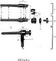
図1に示すアセンブリは脊柱の二つの隣接椎体10の安定化のために用いられる。これは二本の茎ねじ1を含む。この茎ねじ1は、椎体10への導入用の、図2b及び図2cに詳細に示されるテーパ付き第一端3を備えるねじ軸部2と、第二端5を備える頭部4とを有する。
【0021】
茎ねじは、チタンで造られ、その直径は7mm(これは5と8mmの間で変化してもよい)である。茎ねじのねじ部の長さは45mm(これは5mmの増分にて、35と55mmの間で変化してもよい)である。その第二端までの頭部の長さは30mm(これは20と40mmの間で変化してもよい)である。
【0022】
図2aに示すように、二つの端部8を有する可撓性長手支持部材6は、茎ねじ1に対し横断的に配置可能であり、図1に示すように前記第二端から15mm(これは10と20mmの間で変化してもよい)の距離にて、二本の茎ねじ1の頭部4に対し端部8を固定可能である。支持部材6の主要体9は、22,500kg/cm2 (これは17,000と28,000kg/cm2 の間で変化してもよい) の弾性係数を有する高密度ポリエチレン(HDP)、または4,750kg/cm2 (これは3,000と4,500kg/cm2 の間で変化してもよい) の弾性係数を有するポリテトラ−フルオロエチレン(PTFE)のような、可撓性材料からなっている。二つの端部8は、支持部材の可撓性材料の両端に亘る15と20mmの間の長さの、金属スリーブからなっている。これらの金属端部8の外径は、6mm(これは5と8mmの間で変化してもよい)である。支持部材6は、両端に比較して中間部が大きな直径を有するドラム形である。支持部材は、少なくとも部分的に長手方向に圧縮可能である。
【0023】
図3及び図4に示すように、靭帯7は、ループの形を有し、茎ねじの頭部4の円滑部分12に位置すべく、茎ねじの第二端5を通り抜けさせることができる。靭帯の断面の直径は5mm(これは3と7mmの間で変化してもよい)であり、破断強度は引張り荷重において3,500N(これは2,000と4,500Nの間で変化してもよい)である。靭帯の変形率は生理学的荷重の下で20%である。
【0024】
弾性靭帯7は編成ポリマから造られている。靭帯7は前記茎ねじ1に対し横断的に配置され、茎ねじの頭部における支持部材のための溝14から12mm(これは7と17mmの間で変化してもよい)の距離にて茎ねじ1の頭部4に固定される。
【0025】
選択的に、靭帯は、編成ポリエステルの外層と、Dyneema またはその類似品のような伸張可能な材料の内部コアとで造られる単純長さの可撓性コードからなっていてもよい。Dyneema はDSM High Performance Fibres B.V., Netherlandsの登録商標として登録されている。靭帯のこの単純長さ型(上述のループ型に対するものとして)は、茎ねじの第二端5にそれを結合するためのその端部に金属スリーブを有する。
【0026】
図2cに示すように、茎ねじ1の頭部4は、支持部材6の端部8を調整しかつ固定するための固定構造12,14,16を備える。茎ねじ1の頭部4は、靭帯7(図1)を受けるために自由端にある円滑座12、支持部材6の端部8を受けるための溝14、及び該溝14と円滑座12との間に位置しロックナット11を受けるためのねじ部16を備えている。
【0027】
図2cに示すように、茎ねじ1の頭部4は支持部材6の端部8の調整および固定のための三つの部分12,14,16からなっている。これらは、靭帯7を受けるために自由端にある円滑座12、支持部材6の端部8を受けるための溝14、及び円滑座と溝との間に位置していてロックナット11を受けるためのねじ部16である。
【0028】
図2aに示すように、支持部材6の端部8は、スリーブ17及びナット11によって茎ねじの頭部に結合される。この結合構造は、図2bにより詳しく示されている。それは、茎ねじの頭部4における溝14に支持部材6の端部8が入り込んだ後に該端部8を通り抜けさせることができるスリーブ17を含む。それは、さらに、茎ねじの頭部4における対応するねじ部16に螺合し、スリーブ17及び支持部材の端部8を茎ねじに結合するロックナット11を含む。最後に、キャップナット15は、靭帯をあるべき位置に保持すべく、茎ねじの第二端5にねじ込み可能である。
【0029】
図3において、完成されたアセンブリは、二本の茎ねじ1に固定された支持部材6と、茎ねじ1の頭部4に巻かれ堅固にされた靭帯7を示している。
【0030】
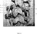
図4において、二対のアセンブリが脊柱モデルに移植されて示されている。右側のアセンブリでは、支持部材6のみが茎ねじ1の頭部4に固定され、左側のアセンブリ(支持部材の異なる型を有する)では、それに靭帯も適用されたものである。
【図面の簡単な説明】
【図1】 本発明に係るアセンブリの縦断面の概要的表現を示す。
【図2a】 本発明に係るアセンブリにおける茎ねじに取り付けられる支持部材の側面を示す。
【図2b】 組立て前における、茎ねじ、それへの支持部材の結合構造、及びキャップナットを示す。
【図2c】 茎ねじ及び結合構造のスリーブの側面を示す。
【図3】 茎ねじ、支持部材、及び靭帯のアセンブリを、脊柱セグメントの一側のために一緒に示す。
【図4】 背面の斜めから腰部脊柱のプラスチックモデルにて示され、一つの脊柱動作セグメントに適用したアセンブリを示す。[0001]
(Technical field)
The invention relates to a device according to the premise characterization part of
[0002]
(Background technology)
The human spinal column consists of an interstitial soft tissue, a block of bone vertebral body with a block of intervertebral disc. These functional elements provide flexibility to the spinal column and allow the load to be transmitted evenly to the lower vertebral body despite changes in the position of the upper vertebral body. They function as a fluid-filled bag between each vertebral body. However, due to disc degeneration, they become anisotropic and transmit loads irregularly to the endplates, and this irregular loading configuration at different positions of the spine is accompanied by back pain.
[0003]
The conventional treatment for this disruption is to fuse the two vertebral bodies. This method of treatment is not accompanied by a high level of success. This is the part associated with the hard segment created by fusion surgery that creates problems for the upper and lower adjacent spinal segments. The ideal solution is to provide normal load transfer and movement as achieved with artificial joints at other sites in the human body. However, the artificial disc prosthesis that has been proposed so far has not yielded any better results than fusion. This is because, in part, the insertion of an artificial disc involves major surgery and it is difficult to accurately place a device that should ensure that the segmental motion of the minor smooth joint remains normal. is there.
[0004]
There are two additional devices described in the treatment of lower back pain, known as soft stabilization, in which the pedicle screw is placed in the vertebral body and subsequently a distractable ligament is attached at their head. In both devices, the re-distraction ligament is well behind the bend / distraction axis. In one of these systems (Dyesys-sulzer), the actual distraction of the dorsal disc space is achieved only by producing a bend in the segment when anterior lordosis is prevented by a cylinder containing the ligament. The It is known that segments in the messy spine can cause back pain.
[0005]
In addition to these systems (Graf ligaments), distraction of the anterior plate space and creation of the physiological vertebral anteroposterior curvature involves compression of the dorsal portion of the disc. This results in a narrowing of the diameter of the exit orifice of the nerve root and an increase in load transmission to the dorsal portion of the disc. Increased load transmission by the dorsal ring can cause ring-shaped tears. Therefore, neither system suggests an important aim of producing uniform disc distraction and creating a normal load profile across the spinal endplate.
[0006]
The present invention as set forth in the claims aims at solving the above-mentioned problems. The present invention provides an apparatus as specified in
[0007]
(Disclosure of the Invention)
Clinically, the ligament is applied to the assembly under tension and to the support member under compression at the resting position of the spinal column. Each screw is guided dorsally through the stem on each side so that the screw, support member and ligament assembly is on the right and left sides of the dorsal surface of the vertebral body to be stabilized. If necessary, the same system can be extended more than a single motion segment.
[0008]
The support member is positioned closer to the axis of motion of the spine bend-distraction. When the assembly is introduced into the spinal column, it allows spinal motion in other directions as well as in flexion-distraction. During flexion-distraction, the range of motion of the support member is smaller than that of the ligament because the support member is close to the axis of motion.
[0009]
This ligament actually extends during flexion and returns during distraction. During bending, the support member bends and also compresses itself to some extent. These movements are reversed in distraction. The two ends of the support member are secured to the pedicle screw to prevent any movement at the junction between the pedicle screw and the support member.
[0010]
The pedicle screw is preferably made of titanium, with diameters of 5, 6, 7, and 8 mm. The pedicle screw has a head portion and a screw shaft portion. The screw shaft length is preferably between 35 and 55 mm in 5 mm increments. The head length is preferably different sizes, for example 20, 30 and 40 mm.
[0011]
The distance x is preferably in the range of 10 to 20 mm, and the distance y is preferably in the range of 7 to 17 mm (FIG. 1).
[0012]
The support member should be at least partially compressible in the longitudinal direction. In a preferred form, the support member consists of a longitudinal main body made of a flexible material at least in the middle, and two ends made of a hard material (e.g. the same as that of a pedicle screw). The two ends are designed as sleeves across the ends of the main body.
[0013]
Main body of the support member, a flexible polymer, for example, between a high-density polyethylene having a modulus of elasticity of between 17,000 to 28,000kg / cm2 (HPD), or from 3000 to 6500kg / cm2 It is preferably made from polytetrafluoroethylene having an elastic modulus. The outer diameter at the metal end of the support member is preferably 5, 6 or 7 mm. The flexibility of the support member depends on the design and diameter.
[0014]
The support member is preferably covered with a fabric sleeve. This has the advantage that it can resist wear in the spine due to friction of the relatively soft material of the support member against the bone and surrounding soft tissue. Preferably, the support member has a drum shape to prevent buckling during bending.
[0015]
Preferably, the head of the pedicle screw has a fixing structure for adjusting and fixing the end of the support member. The head of the pedicle screw includes a smooth seat for receiving a ligament, a groove for receiving an end portion of a support member, and a screw portion for receiving a lock nut.
[0016]
In a preferred embodiment, the assembly has a coupling structure for securing the end of the support member to the head of the pedicle screw. The coupling structure preferably includes a sleeve that allows the end of the support member to pass through the end of the support member after the end of the support member is seated in a groove in the head of the pedicle screw.
[0017]
In a further preferred form, the assembly includes a lock nut capable of tightening the corresponding thread at the pedicle screw head to couple the end of the sleeve and support member to the pedicle screw head.
[0018]
In a more preferred form, the ligament has a closed loop configuration and can be passed through the second end of the pedicle screw to seat on the smooth portion of the pedicle screw head. It may further include a cap nut that can be screwed into the second end of the pedicle screw to hold the ligament in place.
[0019]
The ligament is preferably made of a knitted polymer. The cross-sectional diameter of the ligament can vary between 3 and 7 mm. Its breaking strength should be between 2000N and 5000N load, depending on the ligament diameter and loading factor. The deformation rate is between 10 and 30% under physiological loading.
[0020]
(Best Mode for Carrying Out the Invention)
The assembly shown in FIG. 1 is used to stabilize two adjacent
[0021]
The pedicle screw is made of titanium and its diameter is 7 mm (this may vary between 5 and 8 mm). The thread length of the pedicle screw is 45 mm (this may vary between 35 and 55 mm in 5 mm increments). The length of the head to its second end is 30 mm (this may vary between 20 and 40 mm).
[0022]
As shown in FIG. 2a, a flexible
[0023]
As shown in FIGS. 3 and 4, the
[0024]
The
[0025]
Optionally, the ligament may consist of a simple length of flexible cord made of an outer layer of knitted polyester and an inner core of stretchable material such as Dyneema or the like. Dyneema is registered as a registered trademark of DSM High Performance Fibers BV, Netherlands. This simple length type of ligament (as opposed to the loop type described above) has a metal sleeve at its end for joining it to the
[0026]
As shown in FIG. 2c, the
[0027]
As shown in FIG. 2 c, the
[0028]
As shown in FIG. 2 a, the end 8 of the
[0029]
In FIG. 3, the completed assembly shows a
[0030]
In FIG. 4, two pairs of assemblies are shown implanted in the spinal column model. In the right-hand assembly, only the
[Brief description of the drawings]
FIG. 1 shows a schematic representation of a longitudinal section of an assembly according to the invention.
Figure 2a shows a side view of a support member attached to a pedicle screw in an assembly according to the present invention.
FIG. 2b shows the pedicle screw, the connecting structure of the support member thereto, and the cap nut before assembly.
FIG. 2c shows a side view of the pedicle screw and sleeve of the connecting structure.
FIG. 3 shows the pedicle screw, support member, and ligament assembly together for one side of the spinal segment.
FIG. 4 shows an assembly applied to one spinal motion segment, shown in a plastic model of the lumbar spine from an oblique back side.
Claims (18)
Translated fromJapanese(A)二つの端部(8) を備え、該端部(8) が、前記茎ねじ(1) に対し横断的に配置可能であって、前記第二端から距離xにて前記二つの茎ねじ(1) の頭部(4) に固定可能である可撓性長手支持部材(6) 、及び
(B)前記二つの茎ねじ(1) に対し横断的に配置可能であって、支持部材の端部(8) から距離y<xにて前記二つの茎ねじ(1) の頭部(4) に固定可能である弾性靭帯(7) によって
特徴づけられる脊柱の二つの隣接椎体の安定化用アセンブリ。Two pedicle screws (1) having a screw shaft (2) with a tapered first end (3) for introduction into the vertebral body (10) and a head (4) with a second end (5) In the stabilization assembly of the two adjacent vertebral bodies (10) of the spinal column,
(A) comprising two ends (8), the ends (8) being transversable with respect to the pedicle screw (1), the two ends being at a distance x from the second end A flexible longitudinal support member (6) which can be fixed to the head (4) of the pedicle screw (1), and (B) transversely arranged with respect to the two pedicle screws (1) Of two adjacent vertebral bodies of the spine characterized by elastic ligaments (7) that can be fixed to the heads (4) of the two pedicle screws (1) at a distance y <x from the end (8) of the member Stabilization assembly.
(A)少なくとも中間部が可撓性材料からなる長手主要体(9) 、及び
(B)剛性材料からなる二つの端部(8) 、
を含むことを特徴とする請求項1から4のいずれか一項に記載のアセンブリ。The support member (6)
(A) a longitudinal main body (9) of which at least an intermediate part is made of a flexible material, and (B) two end parts (8) made of a rigid material,
The assembly according to claim 1, comprising:
Applications Claiming Priority (1)
| Application Number | Priority Date | Filing Date | Title |
|---|---|---|---|
| PCT/CH1999/000612WO2001045576A1 (en) | 1999-12-20 | 1999-12-20 | Device for the stabilisation of two adjacent verterbral bodies of the spine |
Publications (2)
| Publication Number | Publication Date |
|---|---|
| JP2003517871A JP2003517871A (en) | 2003-06-03 |
| JP4202020B2true JP4202020B2 (en) | 2008-12-24 |
Family
ID=4551754
Family Applications (1)
| Application Number | Title | Priority Date | Filing Date |
|---|---|---|---|
| JP2001546318AExpired - Fee RelatedJP4202020B2 (en) | 1999-12-20 | 1999-12-20 | Device for stabilization of two adjacent vertebral bodies of the spine |
Country Status (14)
| Country | Link |
|---|---|
| EP (1) | EP1239785B1 (en) |
| JP (1) | JP4202020B2 (en) |
| AT (1) | ATE274853T1 (en) |
| AU (1) | AU767854B2 (en) |
| BR (1) | BR9917579B1 (en) |
| CA (1) | CA2394817A1 (en) |
| DE (1) | DE69919912T2 (en) |
| DK (1) | DK1239785T3 (en) |
| ES (1) | ES2224719T3 (en) |
| HK (1) | HK1048747B (en) |
| MX (1) | MXPA02004117A (en) |
| NZ (1) | NZ518316A (en) |
| PT (1) | PT1239785E (en) |
| WO (1) | WO2001045576A1 (en) |
Families Citing this family (137)
| Publication number | Priority date | Publication date | Assignee | Title |
|---|---|---|---|---|
| FR2812185B1 (en) | 2000-07-25 | 2003-02-28 | Spine Next Sa | SEMI-RIGID CONNECTION PIECE FOR RACHIS STABILIZATION |
| FR2812186B1 (en) | 2000-07-25 | 2003-02-28 | Spine Next Sa | FLEXIBLE CONNECTION PIECE FOR SPINAL STABILIZATION |
| US7833250B2 (en) | 2004-11-10 | 2010-11-16 | Jackson Roger P | Polyaxial bone screw with helically wound capture connection |
| US20050080486A1 (en) | 2000-11-29 | 2005-04-14 | Fallin T. Wade | Facet joint replacement |
| US6579319B2 (en) | 2000-11-29 | 2003-06-17 | Medicinelodge, Inc. | Facet joint replacement |
| US6419703B1 (en) | 2001-03-01 | 2002-07-16 | T. Wade Fallin | Prosthesis for the replacement of a posterior element of a vertebra |
| US6565605B2 (en) | 2000-12-13 | 2003-05-20 | Medicinelodge, Inc. | Multiple facet joint replacement |
| US7090698B2 (en) | 2001-03-02 | 2006-08-15 | Facet Solutions | Method and apparatus for spine joint replacement |
| US7862587B2 (en) | 2004-02-27 | 2011-01-04 | Jackson Roger P | Dynamic stabilization assemblies, tool set and method |
| US10729469B2 (en) | 2006-01-09 | 2020-08-04 | Roger P. Jackson | Flexible spinal stabilization assembly with spacer having off-axis core member |
| US10258382B2 (en) | 2007-01-18 | 2019-04-16 | Roger P. Jackson | Rod-cord dynamic connection assemblies with slidable bone anchor attachment members along the cord |
| SK1002004A3 (en)* | 2001-08-20 | 2004-08-03 | Synthes Ag | Interspinal prosthesis |
| GB2382304A (en)* | 2001-10-10 | 2003-05-28 | Dilip Kumar Sengupta | An assembly for soft stabilisation of vertebral bodies of the spine |
| EP1364622B1 (en) | 2002-05-21 | 2005-07-20 | Spinelab GmbH | Elastical system for stabilising the spine |
| US7052497B2 (en)* | 2002-08-14 | 2006-05-30 | Sdgi Holdings, Inc. | Techniques for spinal surgery and attaching constructs to vertebral elements |
| US8876868B2 (en) | 2002-09-06 | 2014-11-04 | Roger P. Jackson | Helical guide and advancement flange with radially loaded lip |
| US7887539B2 (en) | 2003-01-24 | 2011-02-15 | Depuy Spine, Inc. | Spinal rod approximators |
| EP1444959A1 (en)* | 2003-02-07 | 2004-08-11 | DSM IP Assets B.V. | Bone fixing device |
| US8540753B2 (en) | 2003-04-09 | 2013-09-24 | Roger P. Jackson | Polyaxial bone screw with uploaded threaded shank and method of assembly and use |
| US7621918B2 (en) | 2004-11-23 | 2009-11-24 | Jackson Roger P | Spinal fixation tool set and method |
| US7635379B2 (en) | 2003-05-02 | 2009-12-22 | Applied Spine Technologies, Inc. | Pedicle screw assembly with bearing surfaces |
| US7615068B2 (en) | 2003-05-02 | 2009-11-10 | Applied Spine Technologies, Inc. | Mounting mechanisms for pedicle screws and related assemblies |
| US8652175B2 (en) | 2003-05-02 | 2014-02-18 | Rachiotek, Llc | Surgical implant devices and systems including a sheath member |
| CA2524145A1 (en) | 2003-05-02 | 2004-11-18 | Yale University | Dynamic spine stabilizer |
| US7377923B2 (en) | 2003-05-22 | 2008-05-27 | Alphatec Spine, Inc. | Variable angle spinal screw assembly |
| US8926670B2 (en) | 2003-06-18 | 2015-01-06 | Roger P. Jackson | Polyaxial bone screw assembly |
| US7766915B2 (en) | 2004-02-27 | 2010-08-03 | Jackson Roger P | Dynamic fixation assemblies with inner core and outer coil-like member |
| US8366753B2 (en) | 2003-06-18 | 2013-02-05 | Jackson Roger P | Polyaxial bone screw assembly with fixed retaining structure |
| US7967850B2 (en) | 2003-06-18 | 2011-06-28 | Jackson Roger P | Polyaxial bone anchor with helical capture connection, insert and dual locking assembly |
| US7776067B2 (en) | 2005-05-27 | 2010-08-17 | Jackson Roger P | Polyaxial bone screw with shank articulation pressure insert and method |
| US7588590B2 (en) | 2003-12-10 | 2009-09-15 | Facet Solutions, Inc | Spinal facet implant with spherical implant apposition surface and bone bed and methods of use |
| US7553320B2 (en)* | 2003-12-10 | 2009-06-30 | Warsaw Orthopedic, Inc. | Method and apparatus for replacing the function of facet joints |
| US11419642B2 (en) | 2003-12-16 | 2022-08-23 | Medos International Sarl | Percutaneous access devices and bone anchor assemblies |
| US7527638B2 (en) | 2003-12-16 | 2009-05-05 | Depuy Spine, Inc. | Methods and devices for minimally invasive spinal fixation element placement |
| US7179261B2 (en) | 2003-12-16 | 2007-02-20 | Depuy Spine, Inc. | Percutaneous access devices and bone anchor assemblies |
| US7806914B2 (en) | 2003-12-31 | 2010-10-05 | Spine Wave, Inc. | Dynamic spinal stabilization system |
| US20050171608A1 (en) | 2004-01-09 | 2005-08-04 | Sdgi Holdings, Inc. | Centrally articulating spinal device and method |
| US7556651B2 (en) | 2004-01-09 | 2009-07-07 | Warsaw Orthopedic, Inc. | Posterior spinal device and method |
| US8333789B2 (en) | 2007-01-10 | 2012-12-18 | Gmedelaware 2 Llc | Facet joint replacement |
| US8562649B2 (en) | 2004-02-17 | 2013-10-22 | Gmedelaware 2 Llc | System and method for multiple level facet joint arthroplasty and fusion |
| US7993373B2 (en) | 2005-02-22 | 2011-08-09 | Hoy Robert W | Polyaxial orthopedic fastening apparatus |
| US8152810B2 (en) | 2004-11-23 | 2012-04-10 | Jackson Roger P | Spinal fixation tool set and method |
| US7160300B2 (en) | 2004-02-27 | 2007-01-09 | Jackson Roger P | Orthopedic implant rod reduction tool set and method |
| US11241261B2 (en) | 2005-09-30 | 2022-02-08 | Roger P Jackson | Apparatus and method for soft spinal stabilization using a tensionable cord and releasable end structure |
| JP2007525274A (en) | 2004-02-27 | 2007-09-06 | ロジャー・ピー・ジャクソン | Orthopedic implant rod reduction instrument set and method |
| US7717939B2 (en) | 2004-03-31 | 2010-05-18 | Depuy Spine, Inc. | Rod attachment for head to head cross connector |
| WO2005117725A2 (en) | 2004-05-27 | 2005-12-15 | Depuy Spine, Inc. | Tri-joint implant |
| US7507242B2 (en) | 2004-06-02 | 2009-03-24 | Facet Solutions | Surgical measurement and resection framework |
| US7758581B2 (en) | 2005-03-28 | 2010-07-20 | Facet Solutions, Inc. | Polyaxial reaming apparatus and method |
| US8764801B2 (en) | 2005-03-28 | 2014-07-01 | Gmedelaware 2 Llc | Facet joint implant crosslinking apparatus and method |
| US8858599B2 (en) | 2004-06-09 | 2014-10-14 | Warsaw Orthopedic, Inc. | Systems and methods for flexible spinal stabilization |
| US7931675B2 (en) | 2004-06-23 | 2011-04-26 | Yale University | Dynamic stabilization device including overhanging stabilizing member |
| US8021428B2 (en) | 2004-06-30 | 2011-09-20 | Depuy Spine, Inc. | Ceramic disc prosthesis |
| US7261738B2 (en) | 2004-06-30 | 2007-08-28 | Depuy Spine, Inc. | C-shaped disc prosthesis |
| US7351261B2 (en) | 2004-06-30 | 2008-04-01 | Depuy Spine, Inc. | Multi-joint implant |
| DE202004020396U1 (en) | 2004-08-12 | 2005-07-07 | Columbus Trading-Partners Pos und Brendel GbR (vertretungsberechtigte Gesellschafter Karin Brendel, 95503 Hummeltal und Bohumila Pos, 95445 Bayreuth) | Child seat for motor vehicles |
| US7717938B2 (en) | 2004-08-27 | 2010-05-18 | Depuy Spine, Inc. | Dual rod cross connectors and inserter tools |
| US7651502B2 (en) | 2004-09-24 | 2010-01-26 | Jackson Roger P | Spinal fixation tool set and method for rod reduction and fastener insertion |
| US8092496B2 (en) | 2004-09-30 | 2012-01-10 | Depuy Spine, Inc. | Methods and devices for posterior stabilization |
| US20060084976A1 (en) | 2004-09-30 | 2006-04-20 | Depuy Spine, Inc. | Posterior stabilization systems and methods |
| US7896906B2 (en) | 2004-12-30 | 2011-03-01 | Depuy Spine, Inc. | Artificial facet joint |
| US8926672B2 (en) | 2004-11-10 | 2015-01-06 | Roger P. Jackson | Splay control closure for open bone anchor |
| US9980753B2 (en) | 2009-06-15 | 2018-05-29 | Roger P Jackson | pivotal anchor with snap-in-place insert having rotation blocking extensions |
| WO2006057837A1 (en) | 2004-11-23 | 2006-06-01 | Jackson Roger P | Spinal fixation tool attachment structure |
| US9168069B2 (en) | 2009-06-15 | 2015-10-27 | Roger P. Jackson | Polyaxial bone anchor with pop-on shank and winged insert with lower skirt for engaging a friction fit retainer |
| US8444681B2 (en) | 2009-06-15 | 2013-05-21 | Roger P. Jackson | Polyaxial bone anchor with pop-on shank, friction fit retainer and winged insert |
| US9216041B2 (en) | 2009-06-15 | 2015-12-22 | Roger P. Jackson | Spinal connecting members with tensioned cords and rigid sleeves for engaging compression inserts |
| US7604654B2 (en) | 2005-02-22 | 2009-10-20 | Stryker Spine | Apparatus and method for dynamic vertebral stabilization |
| US7901437B2 (en) | 2007-01-26 | 2011-03-08 | Jackson Roger P | Dynamic stabilization member with molded connection |
| US10076361B2 (en) | 2005-02-22 | 2018-09-18 | Roger P. Jackson | Polyaxial bone screw with spherical capture, compression and alignment and retention structures |
| US7951172B2 (en) | 2005-03-04 | 2011-05-31 | Depuy Spine Sarl | Constrained motion bone screw assembly |
| US7951175B2 (en) | 2005-03-04 | 2011-05-31 | Depuy Spine, Inc. | Instruments and methods for manipulating a vertebra |
| US7722647B1 (en) | 2005-03-14 | 2010-05-25 | Facet Solutions, Inc. | Apparatus and method for posterior vertebral stabilization |
| US20060229607A1 (en)* | 2005-03-16 | 2006-10-12 | Sdgi Holdings, Inc. | Systems, kits and methods for treatment of the spinal column using elongate support members |
| ES2556111T3 (en) | 2005-04-08 | 2016-01-13 | Paradigm Spine, Llc | Interspinous vertebral and lumbosacral stabilization devices |
| WO2006116853A1 (en)* | 2005-05-02 | 2006-11-09 | Kinetic Spine Technologies Inc. | Spinal stabilisation implant |
| NL1029568C2 (en) | 2005-07-20 | 2007-01-23 | Axis Spine | Medical device for positioning bone parts, in particular vertebrae, relative to each other. |
| US7713288B2 (en) | 2005-08-03 | 2010-05-11 | Applied Spine Technologies, Inc. | Spring junction and assembly methods for spinal device |
| US7699875B2 (en) | 2006-04-17 | 2010-04-20 | Applied Spine Technologies, Inc. | Spinal stabilization device with weld cap |
| EP1942817B1 (en) | 2005-09-27 | 2014-05-07 | Paradigm Spine, LLC | Interspinous vertebral stabilization devices |
| US7993376B2 (en) | 2005-09-29 | 2011-08-09 | Depuy Spine, Inc. | Methods of implanting a motion segment repair system |
| US7722651B2 (en) | 2005-10-21 | 2010-05-25 | Depuy Spine, Inc. | Adjustable bone screw assembly |
| US8357181B2 (en) | 2005-10-27 | 2013-01-22 | Warsaw Orthopedic, Inc. | Intervertebral prosthetic device for spinal stabilization and method of implanting same |
| US8137385B2 (en) | 2005-10-31 | 2012-03-20 | Stryker Spine | System and method for dynamic vertebral stabilization |
| US8348952B2 (en) | 2006-01-26 | 2013-01-08 | Depuy International Ltd. | System and method for cooling a spinal correction device comprising a shape memory material for corrective spinal surgery |
| US7635389B2 (en) | 2006-01-30 | 2009-12-22 | Warsaw Orthopedic, Inc. | Posterior joint replacement device |
| US7927356B2 (en) | 2006-07-07 | 2011-04-19 | Warsaw Orthopedic, Inc. | Dynamic constructs for spinal stabilization |
| US7766942B2 (en) | 2006-08-31 | 2010-08-03 | Warsaw Orthopedic, Inc. | Polymer rods for spinal applications |
| FR2913329B3 (en)* | 2006-10-06 | 2009-05-08 | Henry Graf | INTERVERTEBRAL STABILIZATION ASSEMBLY |
| US8361117B2 (en) | 2006-11-08 | 2013-01-29 | Depuy Spine, Inc. | Spinal cross connectors |
| AR064013A1 (en) | 2006-11-30 | 2009-03-04 | Paradigm Spine Llc | VERTEBRAL, INTERLAMINAR, INTERESPINOUS STABILIZATION SYSTEM |
| CA2670988C (en) | 2006-12-08 | 2014-03-25 | Roger P. Jackson | Tool system for dynamic spinal implants |
| CN102525623B (en) | 2006-12-10 | 2015-04-29 | 帕拉迪格脊骨有限责任公司 | Posterior functionally dynamic stabilization system |
| CA2675037A1 (en) | 2007-01-10 | 2008-07-17 | Facet Solutions, Inc. | Taper-locking fixation system |
| US8075596B2 (en) | 2007-01-12 | 2011-12-13 | Warsaw Orthopedic, Inc. | Spinal prosthesis systems |
| US7875059B2 (en) | 2007-01-18 | 2011-01-25 | Warsaw Orthopedic, Inc. | Variable stiffness support members |
| US8475498B2 (en) | 2007-01-18 | 2013-07-02 | Roger P. Jackson | Dynamic stabilization connecting member with cord connection |
| US9414861B2 (en) | 2007-02-09 | 2016-08-16 | Transcendental Spine, Llc | Dynamic stabilization device |
| US8740944B2 (en) | 2007-02-28 | 2014-06-03 | Warsaw Orthopedic, Inc. | Vertebral stabilizer |
| US10383660B2 (en) | 2007-05-01 | 2019-08-20 | Roger P. Jackson | Soft stabilization assemblies with pretensioned cords |
| US8979904B2 (en) | 2007-05-01 | 2015-03-17 | Roger P Jackson | Connecting member with tensioned cord, low profile rigid sleeve and spacer with torsion control |
| NL1033910C1 (en) | 2007-05-31 | 2008-12-02 | Baat Holding B V | Medical device for positioning bone parts, in particular spine, relative to each other, as well as a tool for fitting such a medical device component by component. |
| US8864832B2 (en) | 2007-06-20 | 2014-10-21 | Hh Spinal Llc | Posterior total joint replacement |
| US8048128B2 (en) | 2007-06-05 | 2011-11-01 | Spartek Medical, Inc. | Revision system and method for a dynamic stabilization and motion preservation spinal implantation system and method |
| US10821003B2 (en) | 2007-06-20 | 2020-11-03 | 3Spline Sezc | Spinal osteotomy |
| US8911477B2 (en) | 2007-10-23 | 2014-12-16 | Roger P. Jackson | Dynamic stabilization member with end plate support and cable core extension |
| US8252028B2 (en) | 2007-12-19 | 2012-08-28 | Depuy Spine, Inc. | Posterior dynamic stabilization device |
| US9232968B2 (en) | 2007-12-19 | 2016-01-12 | DePuy Synthes Products, Inc. | Polymeric pedicle rods and methods of manufacturing |
| US8608746B2 (en) | 2008-03-10 | 2013-12-17 | DePuy Synthes Products, LLC | Derotation instrument with reduction functionality |
| US8709015B2 (en) | 2008-03-10 | 2014-04-29 | DePuy Synthes Products, LLC | Bilateral vertebral body derotation system |
| US10973556B2 (en) | 2008-06-17 | 2021-04-13 | DePuy Synthes Products, Inc. | Adjustable implant assembly |
| AU2010260521C1 (en) | 2008-08-01 | 2013-08-01 | Roger P. Jackson | Longitudinal connecting member with sleeved tensioned cords |
| CN103826560A (en) | 2009-06-15 | 2014-05-28 | 罗杰.P.杰克逊 | Polyaxial Bone Anchor with Socket Stem and Winged Inserts with Friction Fit Compression Collars |
| US8998959B2 (en) | 2009-06-15 | 2015-04-07 | Roger P Jackson | Polyaxial bone anchors with pop-on shank, fully constrained friction fit retainer and lock and release insert |
| US11229457B2 (en) | 2009-06-15 | 2022-01-25 | Roger P. Jackson | Pivotal bone anchor assembly with insert tool deployment |
| US9668771B2 (en) | 2009-06-15 | 2017-06-06 | Roger P Jackson | Soft stabilization assemblies with off-set connector |
| US9320543B2 (en) | 2009-06-25 | 2016-04-26 | DePuy Synthes Products, Inc. | Posterior dynamic stabilization device having a mobile anchor |
| US9445844B2 (en) | 2010-03-24 | 2016-09-20 | DePuy Synthes Products, Inc. | Composite material posterior dynamic stabilization spring rod |
| AU2011299558A1 (en) | 2010-09-08 | 2013-05-02 | Roger P. Jackson | Dynamic stabilization members with elastic and inelastic sections |
| AU2011324058A1 (en) | 2010-11-02 | 2013-06-20 | Roger P. Jackson | Polyaxial bone anchor with pop-on shank and pivotable retainer |
| JP5865479B2 (en) | 2011-03-24 | 2016-02-17 | ロジャー・ピー・ジャクソン | Multiaxial bone anchor with compound joint and pop-mounted shank |
| US9907582B1 (en) | 2011-04-25 | 2018-03-06 | Nuvasive, Inc. | Minimally invasive spinal fixation system and related methods |
| US8911479B2 (en) | 2012-01-10 | 2014-12-16 | Roger P. Jackson | Multi-start closures for open implants |
| US8911478B2 (en) | 2012-11-21 | 2014-12-16 | Roger P. Jackson | Splay control closure for open bone anchor |
| US10058354B2 (en) | 2013-01-28 | 2018-08-28 | Roger P. Jackson | Pivotal bone anchor assembly with frictional shank head seating surfaces |
| US8852239B2 (en) | 2013-02-15 | 2014-10-07 | Roger P Jackson | Sagittal angle screw with integral shank and receiver |
| US9566092B2 (en) | 2013-10-29 | 2017-02-14 | Roger P. Jackson | Cervical bone anchor with collet retainer and outer locking sleeve |
| US10438511B2 (en) | 2013-11-11 | 2019-10-08 | K2M, Inc. | Growing spine model |
| US9717533B2 (en) | 2013-12-12 | 2017-08-01 | Roger P. Jackson | Bone anchor closure pivot-splay control flange form guide and advancement structure |
| US9451993B2 (en) | 2014-01-09 | 2016-09-27 | Roger P. Jackson | Bi-radial pop-on cervical bone anchor |
| ES2804126T3 (en) | 2014-02-24 | 2021-02-03 | Univ Curtin Tech | Bra |
| US10758274B1 (en) | 2014-05-02 | 2020-09-01 | Nuvasive, Inc. | Spinal fixation constructs and related methods |
| US10064658B2 (en) | 2014-06-04 | 2018-09-04 | Roger P. Jackson | Polyaxial bone anchor with insert guides |
| US9597119B2 (en) | 2014-06-04 | 2017-03-21 | Roger P. Jackson | Polyaxial bone anchor with polymer sleeve |
| WO2017156596A1 (en) | 2016-03-18 | 2017-09-21 | Curtin University Of Technology | An expandable fastener for orthopaedic applications |
| CN112754634B (en)* | 2021-02-10 | 2022-03-15 | 贺新宁 | Intervertebral space elasticity distraction device |
| US12409046B2 (en) | 2022-04-12 | 2025-09-09 | 3Spine, Inc. | Total spinal joint systems with motion moderators |
Family Cites Families (8)
| Publication number | Priority date | Publication date | Assignee | Title |
|---|---|---|---|---|
| DE3807335A1 (en)* | 1988-03-05 | 1989-09-14 | Orthoplant Endoprothetik | Repositioning and distraction apparatus |
| JP3385018B2 (en)* | 1990-04-19 | 2003-03-10 | ブリアル,フランシス,アンリ | Flexible intervertebral stabilizer and method and apparatus for determining its tension before being attached to the spine |
| FR2666981B1 (en)* | 1990-09-21 | 1993-06-25 | Commarmond Jacques | SYNTHETIC LIGAMENT VERTEBRAL. |
| FR2676911B1 (en)* | 1991-05-30 | 1998-03-06 | Psi Ste Civile Particuliere | INTERVERTEBRAL STABILIZATION DEVICE WITH SHOCK ABSORBERS. |
| DE9112466U1 (en)* | 1991-10-07 | 1991-12-05 | Howmedica GmbH, 2314 Schönkirchen | Device for handling pedicle screws |
| FR2715057B1 (en)* | 1994-01-18 | 1996-03-01 | Francis Henri Breard | Overall device for stabilizing the spine. |
| ATE180402T1 (en)* | 1994-02-28 | 1999-06-15 | Sulzer Orthopaedie Ag | STABILIZATION OF ADJACENT BACK VERTEBRATE |
| FR2755844B1 (en)* | 1996-11-15 | 1999-01-29 | Stryker France Sa | OSTEOSYNTHESIS SYSTEM WITH ELASTIC DEFORMATION FOR SPINE |
- 1999
- 1999-12-20MXMXPA02004117Apatent/MXPA02004117A/ennot_activeIP Right Cessation
- 1999-12-20WOPCT/CH1999/000612patent/WO2001045576A1/enactiveIP Right Grant
- 1999-12-20BRBRPI9917579-7Apatent/BR9917579B1/ennot_activeIP Right Cessation
- 1999-12-20ESES99957834Tpatent/ES2224719T3/ennot_activeExpired - Lifetime
- 1999-12-20ATAT99957834Tpatent/ATE274853T1/ennot_activeIP Right Cessation
- 1999-12-20EPEP99957834Apatent/EP1239785B1/ennot_activeExpired - Lifetime
- 1999-12-20AUAU15451/00Apatent/AU767854B2/ennot_activeCeased
- 1999-12-20DEDE69919912Tpatent/DE69919912T2/ennot_activeExpired - Lifetime
- 1999-12-20CACA002394817Apatent/CA2394817A1/ennot_activeAbandoned
- 1999-12-20PTPT99957834Tpatent/PT1239785E/enunknown
- 1999-12-20DKDK99957834Tpatent/DK1239785T3/enactive
- 1999-12-20NZNZ518316Apatent/NZ518316A/ennot_activeIP Right Cessation
- 1999-12-20JPJP2001546318Apatent/JP4202020B2/ennot_activeExpired - Fee Related
- 1999-12-20HKHK03100678.6Apatent/HK1048747B/ennot_activeIP Right Cessation
Also Published As
| Publication number | Publication date |
|---|---|
| AU767854B2 (en) | 2003-11-27 |
| EP1239785B1 (en) | 2004-09-01 |
| DK1239785T3 (en) | 2004-11-29 |
| BR9917579A (en) | 2002-08-06 |
| HK1048747B (en) | 2004-12-31 |
| EP1239785A1 (en) | 2002-09-18 |
| WO2001045576A1 (en) | 2001-06-28 |
| BR9917579B1 (en) | 2008-11-18 |
| DE69919912T2 (en) | 2005-09-15 |
| MXPA02004117A (en) | 2002-10-17 |
| PT1239785E (en) | 2005-01-31 |
| CA2394817A1 (en) | 2001-06-28 |
| NZ518316A (en) | 2003-05-30 |
| ES2224719T3 (en) | 2005-03-01 |
| DE69919912D1 (en) | 2004-10-07 |
| HK1048747A1 (en) | 2003-04-17 |
| ATE274853T1 (en) | 2004-09-15 |
| JP2003517871A (en) | 2003-06-03 |
| AU1545100A (en) | 2001-07-03 |
Similar Documents
| Publication | Publication Date | Title |
|---|---|---|
| JP4202020B2 (en) | Device for stabilization of two adjacent vertebral bodies of the spine | |
| US8702760B2 (en) | Dynamic spinal stabilization system | |
| US8252028B2 (en) | Posterior dynamic stabilization device | |
| AU2002213257B2 (en) | Anchoring devices and implants for intervertebral disc augmentation | |
| US7338525B2 (en) | Methods and apparatus for preventing the migration of intradiscal devices | |
| US7101398B2 (en) | Prosthetic facet joint ligament | |
| US5540688A (en) | Intervertebral stabilization device incorporating dampers | |
| US20080183292A1 (en) | Compliant intervertebral prosthetic devices employing composite elastic and textile structures | |
| US20070233064A1 (en) | Apparatus and method for flexible spinal fixation | |
| JP2008543451A (en) | Multi-level multifunction spine stabilization system | |
| AU2002213257A1 (en) | Anchoring devices and implants for intervertebral disc augmentation | |
| AU2007249566A1 (en) | Load bearing flexible spinal connecting element | |
| CA2542144A1 (en) | Semi-constrained and mobile-bearing disc prosthesis | |
| US20200289164A1 (en) | Flexible spine stabilization system | |
| ZA200202586B (en) | Device for the stabilisation of two adjacent vertebral bodies of the spine. | |
| US20090088855A1 (en) | Posterior rod capturing spacer device and method | |
| AU2005203715A1 (en) | Anchoring devices and implants for intervertebral disc augmentation |
Legal Events
| Date | Code | Title | Description |
|---|---|---|---|
| A621 | Written request for application examination | Free format text:JAPANESE INTERMEDIATE CODE: A621 Effective date:20061203 | |
| A711 | Notification of change in applicant | Free format text:JAPANESE INTERMEDIATE CODE: A711 Effective date:20061219 | |
| A131 | Notification of reasons for refusal | Free format text:JAPANESE INTERMEDIATE CODE: A131 Effective date:20071120 | |
| RD02 | Notification of acceptance of power of attorney | Free format text:JAPANESE INTERMEDIATE CODE: A7422 Effective date:20080117 | |
| A601 | Written request for extension of time | Free format text:JAPANESE INTERMEDIATE CODE: A601 Effective date:20080127 | |
| A602 | Written permission of extension of time | Free format text:JAPANESE INTERMEDIATE CODE: A602 Effective date:20080204 | |
| TRDD | Decision of grant or rejection written | ||
| A01 | Written decision to grant a patent or to grant a registration (utility model) | Free format text:JAPANESE INTERMEDIATE CODE: A01 Effective date:20080917 | |
| A01 | Written decision to grant a patent or to grant a registration (utility model) | Free format text:JAPANESE INTERMEDIATE CODE: A01 | |
| A61 | First payment of annual fees (during grant procedure) | Free format text:JAPANESE INTERMEDIATE CODE: A61 Effective date:20081008 | |
| R150 | Certificate of patent or registration of utility model | Free format text:JAPANESE INTERMEDIATE CODE: R150 | |
| FPAY | Renewal fee payment (event date is renewal date of database) | Free format text:PAYMENT UNTIL: 20111017 Year of fee payment:3 | |
| FPAY | Renewal fee payment (event date is renewal date of database) | Free format text:PAYMENT UNTIL: 20121017 Year of fee payment:4 | |
| FPAY | Renewal fee payment (event date is renewal date of database) | Free format text:PAYMENT UNTIL: 20131017 Year of fee payment:5 | |
| R250 | Receipt of annual fees | Free format text:JAPANESE INTERMEDIATE CODE: R250 | |
| R250 | Receipt of annual fees | Free format text:JAPANESE INTERMEDIATE CODE: R250 | |
| R250 | Receipt of annual fees | Free format text:JAPANESE INTERMEDIATE CODE: R250 | |
| R250 | Receipt of annual fees | Free format text:JAPANESE INTERMEDIATE CODE: R250 | |
| R250 | Receipt of annual fees | Free format text:JAPANESE INTERMEDIATE CODE: R250 | |
| LAPS | Cancellation because of no payment of annual fees |