JP4201487B2 - Electric tool - Google Patents
Electric toolDownload PDFInfo
- Publication number
- JP4201487B2 JP4201487B2JP2001058630AJP2001058630AJP4201487B2JP 4201487 B2JP4201487 B2JP 4201487B2JP 2001058630 AJP2001058630 AJP 2001058630AJP 2001058630 AJP2001058630 AJP 2001058630AJP 4201487 B2JP4201487 B2JP 4201487B2
- Authority
- JP
- Japan
- Prior art keywords
- housing
- speed reduction
- reduction mechanism
- elastic body
- electric tool
- Prior art date
- Legal status (The legal status is an assumption and is not a legal conclusion. Google has not performed a legal analysis and makes no representation as to the accuracy of the status listed.)
- Expired - Lifetime
Links
Images


Classifications
- B—PERFORMING OPERATIONS; TRANSPORTING
- B25—HAND TOOLS; PORTABLE POWER-DRIVEN TOOLS; MANIPULATORS
- B25F—COMBINATION OR MULTI-PURPOSE TOOLS NOT OTHERWISE PROVIDED FOR; DETAILS OR COMPONENTS OF PORTABLE POWER-DRIVEN TOOLS NOT PARTICULARLY RELATED TO THE OPERATIONS PERFORMED AND NOT OTHERWISE PROVIDED FOR
- B25F5/00—Details or components of portable power-driven tools not particularly related to the operations performed and not otherwise provided for
- B25F5/02—Construction of casings, bodies or handles
Landscapes
- Engineering & Computer Science (AREA)
- Mechanical Engineering (AREA)
- Portable Power Tools In General (AREA)
Description
Translated fromJapanese【0001】
【発明の属する技術分野】
本発明は、電動工具の防振構造に関するものである。
【0002】
【従来の技術】
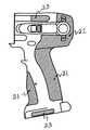
従来における電動工具の防振構造を図7及び図8を用いて説明する。図7は従来における電動工具の二つ割ハウジングを示す側面図、図8は図7に示す二つ割ハウジングの一方を示すその正面図である。図7及び図8において、二つ割ハウジングの表面には、軟質材よりなる当て部21,22,23が設けられている。この当て部は、作業者が電動工具を確実に把持するための滑り止め機能、或いは握り心地を良くし操作性及び作業性を向上させるものである。また、地面に落とした時の衝撃を吸収することで電動工具が破損してしまうことを防いだり、傾斜面に電動工具を置いた時に傾斜に沿って電動工具が滑り落ちないようにするものである。そのため、上記当て部は、主に二つ割ハウジングのハンドル握り部21、胴体部後面22、蓄電池収容部周辺23に設けられている。
【0003】
【発明が解決しようとする課題】
軟質材は、電動工具の操作性及び工具接地面の保護を目的として設けられているが、電動工具の防振或いはシール性を考慮し設けられているものではなかった。よって、防振やシール性を確保するためには、別途、ダンパやパッキン等の部品を設ける必要があり、コスト高になってしまうという問題があった。
【0004】
本発明の目的は、上記問題を解消し、ハウジングの表面に二層成形にて施したゴム部材等の弾性体により、振動を吸収し且つシール性を確保できる電動工具を提供することである。
【0005】
【課題を解決するための手段】
上記目的は、モータと、該モータの回転動力を伝達する減速機構部と、該減速機構部の回転動力を打撃力に変換する打撃機構部と、該モータ及び該減速機構部を収容し、外側の表面に二層成形により第1の弾性体を備えた二つ割ハウジングと、該二つ割ハウジングと隣接して該打撃機構部を収容するハンマケースと、を備えた電動工具において、該二つ割ハウジングの該ハンマケースとの当接部に該第1の弾性体とつながるように第2の弾性体を一体に連続するように設けることにより達成される。
【0006】
【発明の実施の形態】
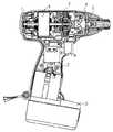
以下、本実施例における電動工具を図1〜図6を用いて説明する。図1は本実施例における電池式回転打撃工具を示す断面図であり、この電池式回転打撃工具は、外枠となるハウジング1、ハンマケース2、電源である充電電池3、本体を駆動するスイッチ4、充電電池3との接点となるスイッチターミナル部5、駆動源であるモータ部6、モータ部6から回転出力を減速する減速機構7、減速機構7からの回転出力を回転打撃へと変換する回転打撃機構8を有している。
【0007】
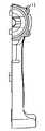
図2はゴム部材等の弾性体(弾性ゴム)にて二層成形処理が施されたハウジング1を示す図1の正面図、図3は図2の側面図である。なお、図中の斜線部は、ゴム部材等の弾性体で二層成形処理を施した部分を示している。図2及び図3において、ハウジング1とハンマケース2との当接面11には、二層成形処理が施されており、施された弾性体により回転打撃機構7の打撃時に発生する軸方向の振動を緩和することができる。更にハウジング1とハンマケース2との間の気密性を確保することにより、減速機構6及び回転打撃機構7に充填されているグリス等の潤滑材がハウジング1外に漏れ出てしまうことを防ぐことができる。
【0008】
また、ハウジング1の電池挿入部12、スイッチ保持部13、減速機構6との勘合部14、ハウジング1と二つ割りの他方のハウジングとの合わせ部15に二層成形処理を施すことで、打撃時に発生する振動に起因するハウシング1と充電電池3との間に生ずる摩耗及びスイッチターミナル部5と充電電池3の端子部との間での振動に起因するチャタリングによる酸化物の発生による導通不良を防ぐことができ、ハウジング1、充電電池3の寿命を向上させることができる。
【0009】
また、ハウジング1内の減速機構7との勘合部14への二層成形処理は、図4及び図5に示すように減速機構7中のインナカバ周止め部16及びハウジング1との突き当て部17、側面部18に施している。これにより、回転打撃機構7にて打撃時に発生する軸、径の両方向の振動に対して防振効果を得られる。
【0010】
また、ハウジング1のスイッチ保持部13への二層成形処理は、回転打撃機構7にて打撃時に発生する振動により、摩耗の影響でスイッチ4の接点部が位置ずれを起こすことに起因する導通不良を防ぎ、スイッチの寿命の向上を図れる。
【0011】
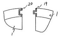
図6はハウジング1の合わせ部側面図で、上記合わせ部に二層成形処理されたゴム部材等の弾性体にて、一方に凸形状のつば19を有し、他方には凸形状のつばと勘合する凹形溝20を設けたことにより接触面積を大きくすることにより、振動の低減及び合わせ部におけるグリス漏れの防げる。
【0012】
【発明の効果】
本発明によれば、電動工具のハウジングにゴム部材等の弾性体にて二層成形処理を施す際、ハンマケース、充電電池等のハウジングと接合する部品との当接面に二層成形処理を行うことにより、新たな部品を用いることなくダンパ、シール性が付加でき、製品本体の寿命及び操作性の向上を図ることができる。
【0013】
また、ハウジング合わせ部に配設した凸形状のつばと勘合する凹形溝にも二層成形処理を行うことにより、両者の接触面積が増すことに起因する更なるダンパ、シール性の効果が得られる。
【図面の簡単な説明】
【図1】 本発明になる電池式回転打撃工具を示す断面図である。
【図2】 図1に示す電池式回転打撃工具の二つ割ハウジングを示す正面図である。
【図3】 図2に示す二つ割ハウジングの側面図である。
【図4】 本発明になる減速機構と二つ割ハウジングとの合わせ面を示す縦断側面図である。
【図5】 図4の側面図である。
【図6】 本発明になる二つ割ハウジングの合わせ面を示す要部拡大図である。
【図7】 従来の電池式回転打撃工具の二つ割ハウジングを示す側面図である。
【図8】 図7に示す二つ割ハウジングの正面図である。
【符号の説明】
1はハウジング、2はハンマケース、3は充電電池、4はスイッチ、5はスイッチターミナル、6はモータ、7は減速機構部、8は回転打撃部、11はハウジングとハンマケースの接合部、12はハウジングの充電電池挿入部、13はハウジングをスイッチの接合部、14はハウジングと減速機構との勘合部、15は二つ割ハウジングの合せ部、16は減速機構周り止め部、17は減速機構突き当て部、18は減速機構側面部、19は凸形状のつば、20は凹形溝、21はハンドル握り部、22は胴体部後面、23は側当て面である。[0001]
BACKGROUND OF THE INVENTION
The present invention relates to an anti-vibration structure for a power tool.
[0002]
[Prior art]
A conventional vibration-proof structure of an electric tool will be described with reference to FIGS. FIG. 7 is a side view showing a conventional split housing of an electric power tool, and FIG. 8 is a front view showing one of the split housings shown in FIG. 7 and 8,
[0003]
[Problems to be solved by the invention]
The soft material is provided for the purpose of operability of the electric tool and protection of the tool grounding surface, but is not provided in consideration of vibration proofing or sealing performance of the electric tool. Therefore, in order to ensure vibration proofing and sealing properties, it is necessary to separately provide components such as a damper and packing, which increases the cost.
[0004]
An object of the present invention is to provide an electric tool capable of solving the above-described problems and absorbing vibration and securing a sealing property by an elastic body such as a rubber member formed on the surface of a housing by two-layer molding.
[0005]
[Means for Solving the Problems]
The object is to accommodate a motor, a speed reduction mechanism portion for transmitting the rotational power of the motor, a striking mechanism portion for converting the rotational power of the speed reduction mechanism portion to a striking force, and the motor and the speed reduction mechanism portion. An electric tool comprising: a split housing having a first elastic body formed by two-layer molding on a surface thereof; and a hammer case that accommodates the striking mechanism portion adjacent to the split housing. This is achieved by providing the second elastic bodyso as to becontinuous with the first elastic body so as to be connected to the first elastic body at the contact portion of the split housing with the hammer case.
[0006]
DETAILED DESCRIPTION OF THE INVENTION
Hereinafter, the electric tool in a present Example is demonstrated using FIGS. FIG. 1 is a cross-sectional view showing a battery-type rotary impact tool in this embodiment. The battery-type rotary impact tool includes a housing 1 as an outer frame, a
[0007]
2 is a front view of FIG. 1 showing a housing 1 subjected to a two-layer molding process with an elastic body (elastic rubber) such as a rubber member, and FIG. 3 is a side view of FIG. Note that the hatched portion in the figure indicates a portion subjected to a two-layer molding process with an elastic body such as a rubber member. 2 and 3, the contact surface 11 between the housing 1 and the
[0008]
In addition, the
[0009]
Further, the two-layer molding process to the
[0010]
In addition, the two-layer molding process for the switch holding portion 13 of the housing 1 is caused by the continuity failure caused by the displacement of the contact portion of the switch 4 due to wear due to the vibration generated at the time of hitting by the rotary hitting mechanism 7. Can be prevented and the life of the switch can be improved.
[0011]
FIG. 6 is a side view of the mating portion of the housing 1, which is an elastic body such as a rubber member that has been subjected to two-layer molding processing on the mating portion, and has a
[0012]
【The invention's effect】
According to the present invention, when the two-layer molding process is performed on the housing of the electric tool with an elastic body such as a rubber member, the two-layer molding process is performed on the contact surface of the hammer case, the rechargeable battery, or the like with the part to be joined. By doing so, a damper and a sealing property can be added without using new parts, and the life and operability of the product body can be improved.
[0013]
In addition, by performing a two-layer molding process on the concave groove that fits into the convex flange disposed in the housing mating part, further damper and sealing effects due to the increase in the contact area between the two can be obtained. It is done.
[Brief description of the drawings]
FIG. 1 is a cross-sectional view showing a battery-type rotary impact tool according to the present invention.
2 is a front view showing a split housing of the battery-type rotary impact tool shown in FIG. 1; FIG.
FIG. 3 is a side view of the split housing shown in FIG. 2;
FIG. 4 is a longitudinal side view showing a mating surface between the speed reduction mechanism and the split housing according to the present invention.
FIG. 5 is a side view of FIG. 4;
FIG. 6 is an enlarged view of a main part showing a mating surface of the split housing according to the present invention.
FIG. 7 is a side view showing a split housing of a conventional battery-type rotary impact tool.
FIG. 8 is a front view of the split housing shown in FIG.
[Explanation of symbols]
1 is a housing, 2 is a hammer case, 3 is a rechargeable battery, 4 is a switch, 5 is a switch terminal, 6 is a motor, 7 is a speed reduction mechanism, 8 is a rotary striking portion, 11 is a joint between the housing and the hammer case, 12 Is a rechargeable battery insertion portion of the housing, 13 is a joint portion of the housing and the switch, 14 is a fitting portion of the housing and the speed reduction mechanism, 15 is a fitting portion of the split housing, 16 is a stop portion around the speed reduction mechanism, and 17 is a speed reduction mechanism The abutting portion, 18 is a speed reducing mechanism side surface portion, 19 is a convex collar, 20 is a concave groove, 21 is a handle grip portion, 22 is a rear surface of the body portion, and 23 is a side abutting surface.
Claims (1)
Translated fromJapanese該モータの回転動力を伝達する減速機構部と、
該減速機構部の回転動力を打撃力に変換する打撃機構部と、
該モータ及び該減速機構部を収容し、外側の表面に二層成形により第1の弾性体を備えた二つ割ハウジングと、
該二つ割ハウジングと隣接して該打撃機構部を収容するハンマケースと、
を備えた電動工具において、
該二つ割ハウジングの該ハンマケースとの当接部に該第1の弾性体とつながるように第2の弾性体を一体に連続するように設けることを特徴とする電動工具。A motor,
A speed reduction mechanism for transmitting the rotational power of the motor;
A striking mechanism for converting the rotational power of the speed reduction mechanism to striking force;
A split housing that houses the motor and the speed reduction mechanism and has a first elastic body formed by two-layer molding on the outer surface;
A hammer case that accommodates the striking mechanism adjacent to the split housing;
In the electric tool with
A power tool characterized in that a second elastic body is provided soas to becontinuous with the first elastic body at a contact portion of the split housing with the hammer case.
Priority Applications (1)
| Application Number | Priority Date | Filing Date | Title |
|---|---|---|---|
| JP2001058630AJP4201487B2 (en) | 2001-03-02 | 2001-03-02 | Electric tool |
Applications Claiming Priority (1)
| Application Number | Priority Date | Filing Date | Title |
|---|---|---|---|
| JP2001058630AJP4201487B2 (en) | 2001-03-02 | 2001-03-02 | Electric tool |
Related Child Applications (1)
| Application Number | Title | Priority Date | Filing Date |
|---|---|---|---|
| JP2006201251ADivisionJP4353213B2 (en) | 2006-07-24 | 2006-07-24 | Electric tool |
Publications (2)
| Publication Number | Publication Date |
|---|---|
| JP2002254356A JP2002254356A (en) | 2002-09-10 |
| JP4201487B2true JP4201487B2 (en) | 2008-12-24 |
Family
ID=18918321
Family Applications (1)
| Application Number | Title | Priority Date | Filing Date |
|---|---|---|---|
| JP2001058630AExpired - LifetimeJP4201487B2 (en) | 2001-03-02 | 2001-03-02 | Electric tool |
Country Status (1)
| Country | Link |
|---|---|
| JP (1) | JP4201487B2 (en) |
Families Citing this family (24)
| Publication number | Priority date | Publication date | Assignee | Title |
|---|---|---|---|---|
| JP4593387B2 (en)* | 2005-07-04 | 2010-12-08 | 株式会社マキタ | Electric tool |
| JP4645332B2 (en)* | 2005-07-08 | 2011-03-09 | 日立工機株式会社 | Portable electric circular saw |
| DE102005052428B4 (en)* | 2005-11-03 | 2015-06-18 | Robert Bosch Gmbh | Power tool |
| JP4894665B2 (en)* | 2007-07-26 | 2012-03-14 | パナソニック電工株式会社 | Portable electric tool |
| US7717191B2 (en) | 2007-11-21 | 2010-05-18 | Black & Decker Inc. | Multi-mode hammer drill with shift lock |
| US7735575B2 (en) | 2007-11-21 | 2010-06-15 | Black & Decker Inc. | Hammer drill with hard hammer support structure |
| US7854274B2 (en) | 2007-11-21 | 2010-12-21 | Black & Decker Inc. | Multi-mode drill and transmission sub-assembly including a gear case cover supporting biasing |
| US7717192B2 (en) | 2007-11-21 | 2010-05-18 | Black & Decker Inc. | Multi-mode drill with mode collar |
| US7762349B2 (en) | 2007-11-21 | 2010-07-27 | Black & Decker Inc. | Multi-speed drill and transmission with low gear only clutch |
| US7770660B2 (en) | 2007-11-21 | 2010-08-10 | Black & Decker Inc. | Mid-handle drill construction and assembly process |
| US7798245B2 (en) | 2007-11-21 | 2010-09-21 | Black & Decker Inc. | Multi-mode drill with an electronic switching arrangement |
| JP5126596B2 (en)* | 2008-06-27 | 2013-01-23 | 日立工機株式会社 | Electric tool |
| JP5368831B2 (en)* | 2009-02-27 | 2013-12-18 | 株式会社マキタ | Handy cleaner |
| JP5352412B2 (en)* | 2009-10-14 | 2013-11-27 | 株式会社マキタ | Electric tool |
| JP5722638B2 (en)* | 2010-09-28 | 2015-05-27 | 株式会社マキタ | Rechargeable power tool |
| EP2885113B1 (en) | 2012-08-14 | 2024-11-20 | Koki Holdings Co., Ltd. | Electric device, battery pack, and electric apparatus |
| JP2014072006A (en) | 2012-09-28 | 2014-04-21 | Hitachi Koki Co Ltd | Battery pack and electric apparatus |
| JP5937940B2 (en)* | 2012-10-02 | 2016-06-22 | 株式会社マキタ | Electric tool |
| JP6111686B2 (en)* | 2013-01-25 | 2017-04-12 | マックス株式会社 | Gas fired driving tool |
| JP6048192B2 (en) | 2013-02-13 | 2016-12-21 | 日立工機株式会社 | Electrical equipment and electrical equipment |
| JP2014197515A (en) | 2013-03-29 | 2014-10-16 | 日立工機株式会社 | Battery pack and electric apparatus |
| JP2020006454A (en)* | 2018-07-04 | 2020-01-16 | 株式会社マキタ | Driving tool |
| JP7658067B2 (en)* | 2020-08-11 | 2025-04-08 | 工機ホールディングス株式会社 | Work equipment |
| CN115592622A (en)* | 2021-07-08 | 2023-01-13 | 南京泉峰科技有限公司(Cn) | electrical tools |
- 2001
- 2001-03-02JPJP2001058630Apatent/JP4201487B2/ennot_activeExpired - Lifetime
Also Published As
| Publication number | Publication date |
|---|---|
| JP2002254356A (en) | 2002-09-10 |
Similar Documents
| Publication | Publication Date | Title |
|---|---|---|
| JP4201487B2 (en) | Electric tool | |
| RU2555289C2 (en) | Hand-held machine with drive motor and transmission gear | |
| US7721818B2 (en) | Power tool having a vibration isolating handle | |
| US7967079B2 (en) | Hand-held power tool | |
| JP5216321B2 (en) | Motor mounting structure | |
| US20130277079A1 (en) | Power tool | |
| JP6440118B2 (en) | Impact rotary tool | |
| JP4353213B2 (en) | Electric tool | |
| US8496073B2 (en) | Portable power tool | |
| US20130220659A1 (en) | Oscillating rotary electric power tool | |
| KR20100109641A (en) | Damper-coupler for electric power steering | |
| CN105856142A (en) | Impact rotation tool | |
| JP2013063494A (en) | Power tool | |
| JP2002153014A (en) | Commutator motor | |
| JP2019214116A (en) | Striking member of power tool impact unit, holder suitable therefor and power tool impact unit | |
| KR0116428Y1 (en) | Coupling for connecting electric motor and reducer of electric vehicle | |
| CN217728644U (en) | Electric tool | |
| JP5045994B2 (en) | Power tool | |
| JP4768241B2 (en) | Propeller shaft boot with bearing seal plate that can be held without using clamps | |
| JP2006035378A (en) | Power tool | |
| WO2008132219A1 (en) | Drive device for operating a vehicle door | |
| EP4571151A1 (en) | Shaft sealing assembly of handheld device, front end waterproof assembly, and host device | |
| JP3729230B2 (en) | Vibration isolator | |
| EP4297933B1 (en) | Power tool having an anti-vibration assembly | |
| US20240364177A1 (en) | Sealing Covers for Actuator Motors |
Legal Events
| Date | Code | Title | Description |
|---|---|---|---|
| A621 | Written request for application examination | Free format text:JAPANESE INTERMEDIATE CODE: A621 Effective date:20040924 | |
| A131 | Notification of reasons for refusal | Free format text:JAPANESE INTERMEDIATE CODE: A131 Effective date:20060523 | |
| A521 | Written amendment | Free format text:JAPANESE INTERMEDIATE CODE: A523 Effective date:20060724 | |
| A02 | Decision of refusal | Free format text:JAPANESE INTERMEDIATE CODE: A02 Effective date:20070123 | |
| A521 | Written amendment | Free format text:JAPANESE INTERMEDIATE CODE: A523 Effective date:20070322 | |
| A911 | Transfer to examiner for re-examination before appeal (zenchi) | Free format text:JAPANESE INTERMEDIATE CODE: A911 Effective date:20070330 | |
| A912 | Re-examination (zenchi) completed and case transferred to appeal board | Free format text:JAPANESE INTERMEDIATE CODE: A912 Effective date:20070727 | |
| A521 | Written amendment | Free format text:JAPANESE INTERMEDIATE CODE: A523 Effective date:20080801 | |
| A01 | Written decision to grant a patent or to grant a registration (utility model) | Free format text:JAPANESE INTERMEDIATE CODE: A01 | |
| A61 | First payment of annual fees (during grant procedure) | Free format text:JAPANESE INTERMEDIATE CODE: A61 Effective date:20081007 | |
| R150 | Certificate of patent or registration of utility model | Free format text:JAPANESE INTERMEDIATE CODE: R150 Ref document number:4201487 Country of ref document:JP Free format text:JAPANESE INTERMEDIATE CODE: R150 | |
| FPAY | Renewal fee payment (event date is renewal date of database) | Free format text:PAYMENT UNTIL: 20111017 Year of fee payment:3 | |
| FPAY | Renewal fee payment (event date is renewal date of database) | Free format text:PAYMENT UNTIL: 20211017 Year of fee payment:13 | |
| R250 | Receipt of annual fees | Free format text:JAPANESE INTERMEDIATE CODE: R250 | |
| S533 | Written request for registration of change of name | Free format text:JAPANESE INTERMEDIATE CODE: R313533 | |
| R350 | Written notification of registration of transfer | Free format text:JAPANESE INTERMEDIATE CODE: R350 | |
| EXPY | Cancellation because of completion of term |