JP4201476B2 - Fingerprint recognition device - Google Patents
Fingerprint recognition deviceDownload PDFInfo
- Publication number
- JP4201476B2 JP4201476B2JP2000314072AJP2000314072AJP4201476B2JP 4201476 B2JP4201476 B2JP 4201476B2JP 2000314072 AJP2000314072 AJP 2000314072AJP 2000314072 AJP2000314072 AJP 2000314072AJP 4201476 B2JP4201476 B2JP 4201476B2
- Authority
- JP
- Japan
- Prior art keywords
- lid
- fingerprint
- operator
- fingerprint recognition
- finger
- Prior art date
- Legal status (The legal status is an assumption and is not a legal conclusion. Google has not performed a legal analysis and makes no representation as to the accuracy of the status listed.)
- Expired - Fee Related
Links
Images


Classifications
- G—PHYSICS
- G06—COMPUTING OR CALCULATING; COUNTING
- G06V—IMAGE OR VIDEO RECOGNITION OR UNDERSTANDING
- G06V40/00—Recognition of biometric, human-related or animal-related patterns in image or video data
- G06V40/10—Human or animal bodies, e.g. vehicle occupants or pedestrians; Body parts, e.g. hands
- G06V40/12—Fingerprints or palmprints
- G06V40/13—Sensors therefor
Landscapes
- Engineering & Computer Science (AREA)
- Human Computer Interaction (AREA)
- Physics & Mathematics (AREA)
- General Physics & Mathematics (AREA)
- Multimedia (AREA)
- Theoretical Computer Science (AREA)
- Image Input (AREA)
- Measurement Of The Respiration, Hearing Ability, Form, And Blood Characteristics Of Living Organisms (AREA)
Description
Translated fromJapanese【0001】
【発明の属する技術分野】
本発明は指紋認識装置に関し、更に詳しくは、デスクトップ式、ラップトップ式、ノート式等、或いは定置式、携帯式等の情報処理装置、例えばパーソナルコンピュータ、携帯電話等の各種の情報処理装置に適用可能な指紋により本人を認証する装置に関する。
【0002】
指紋による本人認識機能は、極めて精度の高い認識機能を有することで知られているが、一方で、人間の指を指紋認識装置で処理する際に、人間の指による静電気によって指紋認識装置が影響を受けることがあるので、このような静電気による影響を防止する手段を講ずることが要求されている。
【0003】
【従来の技術】
情報処理装置において、他人が個人の情報にアクセスしたり、他人名で情報を処理したりするのを防止するために、従来、指紋により本人を認証するシステムを採用してきた。このような、指紋認識機能を有する情報処理装置の幾つかの従来例について説明する。
【0004】
特開平11−185016号では、電源ON操作や指紋照合開始指示等を不要にするために、使用者が指紋検出部に指を押し当てると、指紋検出部では押し当てられた指によってできた影をセンサー部にて検出し、その影の形状が指による影の分布であると判断することにより電源をONにし、その後、押し当てられた指から指紋を検出し、予め記憶された指紋データと照合することにより、使用者を識別し、これによって、識別した使用者に合致するスケジュールデータ等の各種データを利用可能とする情報処理装置が開示されている。
【0005】
特開平11−175478号(EP0923018)に開示された本人認証システムでは、入力装置を小型化でき、他人に利用されないようにするため、コンピュータと、入力装置と、指紋データベースとを有し、入力装置は、キーボードと、これと一体の指紋センサと、表示装置と、アダプタ回路と、指紋照合装置とを有する。そして、指紋センサにより検出された指紋の情報と指紋データベースの指紋の情報とが一致する時にのみログオン処理およびデータ暗号化処理等の処理をする。
【0006】
特開平9−330140号では、煩わしいパスワードを使用せずに、セキュリティを確保できるようにするために、キーボードには、指紋読み取り部1が設けられ、コンピュータ本体には、指紋照合部と指紋記憶部が設けられ、CRTに表示される。操作者が、コンピュータを操作しようとするとき、指を指紋読み取り部に押しつける。指紋読み取り部は内部からの光ビームにより指紋を読みとって、指紋データをパーソナルコンピュータ本体の指紋照合部に送る。指紋照合部は登録済みの指紋データと認識されれば、パーソナルコンピュータ2へのログインを可能とする。
【0007】
特開2000−194830号に開示された、マウス型入力装置は、マウスに外部から接触可能に配設された個体識別情報を検出するセンサと、マウスのユーザの手が接触しやすい位置に配設された電極と、電極に接地電位を供給する手段とを具備する。接地された電極によりユーザに帯電した静電気、マウスの操作により発生する静電気を逃がすことができ、S/N比の高い個体識別情報を検出する。
【0008】
より具体的には、マウスには、ユーザの手が触れやすい位置に電極が配置されていて、マウスを操作するにあたって、ユーザの手がその電極に触れることで、ユーザに帯電しているて静電気を情報処理装置側の基準電圧(グランド)に逃がすようにし、静電気によるノイズの影響で、指紋センサの識別機能が誤作動を起こしたり、指紋センサを含む認証システム自体の機能が阻害されることを防止している。
【0009】
【発明が解決しようとする課題】
以上のように、指紋により本人を認識するシステムを採用した情報処理装置は従来知られている。また、特開2000−194830号では、指紋識別センサの誤作動や機能不全となるのを防止するために、ユーザに帯電しているて静電気を装置側のグランドに逃がして除電を行う機構を設けている。
【0010】
しかしながら、特開2000−194830号に開示された、本人認証システムでは、指紋識別センサに蓋を設けられていて、この蓋を明けてユーザの指を識別センサに挿入して、本人認証を行うのであるが、識別センサにユーザの指が触れる前に、ユーザの手が除電用の電極に触れることが保証されているとは限らず、ユーザは、本人認証の前に必ず自分の手が除電用の電極に触れなければならないことを意識することが必要である。また、この指紋識別センサは、情報処理装置のマウスに設けられているもので、マウスのない、特に携帯型情報処理装置等においては、適用することができない。
【0011】
そこで、本発明は、指紋による本人認証を行うための指紋認識装置において、操作者の指が指紋センサ部に触れる前に、必ず操作者自体が電気的に装置側の基準電位(グランド)と同電位となる、即ち除電されることを保証する、指紋認識装置を提供することを課題とする。
また、本発明は、指紋による本人認証を行うための指紋認識装置において、操作者が除電される前に、操作者の指或いはその他のものが指紋識別センサに不用意に触れることを防止する機能を具備する、携帯型の装置にも適用可能な、指紋認証装置を提供することを課題とする。
【0012】
【課題を解決するための手段】
上記の課題を達成するために、本発明によれば、指紋を検出する指紋センサ部と、該指紋センサ部を保護する蓋部と、該蓋部の操作時に操作者の指が接触可能な位置に設けられると共に装置側のグラント電位に電気的に接続されている接触部と、を具備し、前記蓋部はヒンジ式に開閉可能であって、該蓋部の開放端に隣接した装置筐体側の位置にて、該装置の筐体表面側に操作者の指の一部が嵌まる窪み部が設けられ、該窪み部の中に前記接触部が設けられ、前記蓋部の開放端は、中央部が外方に突出したゆるやかな湾曲形状であり、該湾曲形状に応じて、前記窪み部及び前記接触部も湾曲形状をなしていることを特徴とする指紋認識装置が提供される。
【0013】
情報処理装置の使用を開始するに当たって、本人認証のために指紋センサ面にアクセスする直前に、蓋部開放し、その際、蓋部の開放と同時に操作者の指が接触部に触れるので、操作者が何ら意識していなくても、指紋認識作用の直前に操作者の静電気が装置側のグランド電位に解放される。
上記のような構造により、蓋部のヒンジ部を中心として該蓋部を回転させて開こうとする際に、操作者の指が接触部に触れ易くなる。
【0014】
この場合、蓋部の開放動作がし易くなり、これにより操作者の指の接触部への接触もより確実なものとなる。
前記蓋部の開放端側の位置と、該開放端側の位置に対応する装置筐体側の位置にそれぞれ、該蓋部を装置筐体に対して閉鎖状態にロックするべく互いに係合しあう手段が設けられていることを特徴とする。このような係合手段を設けたことにより、蓋部を開放しようとする際は必ず操作者の指を蓋部の開放端側に引っかけなければならず、したがって操作者が何ら意識していなくても、指紋認証の作用に先立ってしかもその直前に操作者の指が接触部に接触し、静電気を装置グランド側に落とすことができる。
【0015】
前記接触部は、グランド接触板の一部として形成されており、該グランド接触板は、前記接触部の周囲にて装置筐体に固定されていると共に、指紋センサを構成する部材を固定するための固定板と共締めされて装置筐体に固定されていることを特徴とする。この構成によると、簡単なグランド接触板の構造でもって、グランド接触板の装置筐体への固定と、グランド電位である装置筐体への電気的接続とを同時にかつ確実に行うことができる。
【0016】
また、本発明では、上記の指紋認識装置と、データを入力する入力部と、該入力部から入力されたデータを処理する装置本体と、文字や画像を表示するディスプレイとを備えた情報処理装置が提供される。
【0017】
【発明の実施の形態】
以下、添付図面を参照して本発明の実施の形態について詳細に説明する。
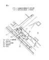
図1は本発明を採用した情報処理装置、特にノートブック型のパーソナルコンピュータの外観斜視図である。図1において、情報処理装置は、装置本体1と、この装置本体1に対してヒンジ部2により回転可能に結合された蓋部3とからなる。これにより、蓋部3は装置本体1に対して開閉可能となっている。
【0018】
蓋部3はこれを閉じると装置本体1の係合部4に蓋部3の係止部5が係合し、蓋部3が不用意に開かないように、蓋部3を閉じた状態で装置本体1に固定できるように構成されている。
装置本体1には、文字、画像、その他のデータを入力するためのキーボード等の入力部6と、指紋認識装置sとが設けられる。この指紋認識装置sは指紋センサ部7と、蓋部30と、接触部23を備えている。操作者の指紋を検出する指紋センサ部7はパームレスト部分10に設けられ、後に詳述するように、指紋センサ部7を保護するための蓋部30が設けられている。
【0019】
装置の蓋部3には、処理すべき文字、画像、その他のデータ等の情報を表示するためのディスプレイ9が設けられており、操作者はこのディスプレイ9を見ながら入力部6のキーボードやマウス(図示せず)を操作する。
図示のような情報処理装置は机などの上に置いて定置式として用いてもよく、また、携帯用として用いてもよいことは勿論である。
【0020】
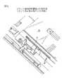
図2及び図3は指紋認識装置の斜視図であって、図2は蓋部30の閉鎖時、図3は蓋部30の開放時をそれぞれ示す。
図示のように、この実施形態においては、指紋センサ部7は情報処理装置の装置本体1の入力部6と略同一の面、特に装置筐体のパームレスト10の表面部分に設けられている。蓋部30を閉鎖した状態で、蓋部30の表面が装置筐体のパームレストの表面と一致してスムーズな平面を形成することで、指紋の認証を行った後、蓋部30を閉じて通常の情報処理装置の操作に入った際に、指紋認識装置がキーボード等の入力部6のデータ入力操作の邪魔になったり、違和感を与えたりすることはなくなる。
【0021】
しかしながら、指紋認識装置は操作者が情報処理装置による操作処理を開始するに当たって、本人認証のために指を押し当てるために都合の良い場所であれば、どの位置にあっても差し支えない。
指紋センサ部7は、装置筐体のパームレスト部10の表面部分より筐体の内部側へ若干窪んでおり、周囲が傾斜部12で、中央部分は指を押し当てるためのセンサガラス面11であり、このセンサガラス面11は装置筐体11のパームレスト表面と略平行な平面になっている。
【0022】
蓋部30は閉鎖時においては、センサガラス面11を完全に覆いセンサガラス面11を含む指紋センサ部7を保護している。蓋部30は装置筐体に対してヒンジ式に開閉可能で、指を引っかけて蓋部30を開放する一端側31と、ヒンジ32を形成する他端側を有し、一端側31に隣接して、ゆるやかな傾斜部12となっており、傾斜部12に窪み部13が設けられている。
【0023】
この窪み部13の中央にある長円形の穴に、後述する接触部23が突出ないし露出している。そして、操作者が蓋部30の開放端部に指を引っかけて蓋部30を開放しようとする際、指の一部が窪み部13に入ると同時に接触部23に確実に接触するような位置関係になっている。これにより、操作者に帯電している静電気の電位を情報処理装置の基準電位であるグランド電位と同電位となる。即ち、操作者の電位が除電される。
【0024】
蓋部30は開放端31の内側には係止突起33が設けられており、一方、筐体側、特に傾斜部12に係止突起33と係合する係止部14が設けられており、蓋部30の閉鎖時は係止突起33が係止部14に弾性的に係合することにより、蓋部30が容易に開放しないようにロックされる。従って、操作者が装置の操作に先立って本人認証のために蓋部30を開放しようとして蓋部30の開放端31に指を引っかけて係止部14と係合突起33によるロックを解体する際に操作者の指が接触部23に確実に触れることとなる。
【0025】
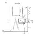
図4及び図5はグランド電位との接触部23及びその周辺を装置筐体の裏面から見た図であり、図4はセンサ固定板を取り外した状態、図5はセンサ固定板を取り付けた状態をそれぞれ示す。また、図6はグランド接触板の斜視図、図7(a)、(b)及び(c)はグランド接触板の3面図、即ち平面図、正面図及び側面図である。
【0026】
グランド接触板20はプレス加工等により形成された1枚の導電性の板金からなり、固定部21、ねじ止め部22、接触部23、折り曲げ部24を有する。固定部21はこのグランド接触板20を装置筐体に固定するためのリベット穴21aを有する。この実施形態では、接触部23の周囲に3つのリベット穴21aが設けられている。接触部23は略長円形の凸部からなり、この凸状の接触部23が前述の窪み部13の長円形の穴に適合する形状を有する。
【0027】
装置筐体のパームレストカバー部にはグランド接触板20のリベット穴の位置に合わせたピン14が裏面より突出しており、グランド接触板20のリベット穴21aをこれらのピン14に挿入した後、樹脂等の熱融着性の材料から成るピン14を公知の方法で熱融着することによりグランド接触板20が装置筐体の裏面に固定される。これにより、凸状の接触部23が窪み部13の面と同一面又はわずかに上方に突出した状態となる。
【0028】
ねじ止め部22は折り曲げ部24を介して固定部21とは反対の側にあり、このグランド接触板20をグランド電位である装置筐体に電気的な接続を行うためのねじ穴22aを有する。ねじ止め部22は装置筐体側のねじ穴(図示せず)にねじ40により固定される。図4ではセンサ固定板を取り外した状態で示しているが、実際は図5のように、ねじ40をセンサ固定板16の隅部にある穴と、グランド接触板20の穴22aに通し、ねじ込むことによりクラッド接触板20とセンサ固定板16とを装置筐体に対して共締めしている。折り曲げ部24は、装置筐体のパームレストの表面部分に出ている接触部23を有する固定部分21と、指紋センサ部の厚みを伴った指紋検出用のプリント板15との間の段差に適合するように設けられたものである。
【0029】
センサ固定板16は、指紋センサ部7を固定するもので、特にセンサガラス面11を含む指紋認識装置の構成要素の部分及び指紋検出用のプリント板15を装置筐体に固定するものである。指紋認識装置それ自体は、前述の従来例、例えば特開平11−185016号に開示されているような構造のものを採用することができる。
【0030】
即ち、センサガラス面11に指を押し当てることにより、その指によってできた影を光学的に検出し、その検出した影の分布形状が、この装置に予め登録されている操作者の指紋の分布形状と照合し、一致すると判断すると、情報処理装置の電源のONを可能としたり、或いは情報処理装置への情報の入力操作を可能としたり、その他特定の処理作業やデータ処理、表示を可能とするように設定されている。一致しないと判断した場合は、これらの操作を不能とすることは勿論である。
【0031】
図2及び図8から明らかなように、蓋部30の開放端側31は中央部分が外側となる緩やかな湾曲形状をしている。その関係で、グランド接触板20の略長円形で凸状の接触部23及びこの接触部23と対応する形状をもった装置筐体側の略長円形穴も蓋部30の開放端側31の湾曲形状に対応するような緩やかな湾曲形状となっている。更に装置筐体側の指の一部が嵌まる窪み部13も接触部23の形状に合わせて同様に緩やかな湾曲形状となっている。
【0032】
【実施例】
図8〜図9において、本発明の情報処理装置における指紋センサ部7の具体的な構造を更に詳細に説明する。例えば、図8において典型的な実施例における寸法関係を説明すると、蓋部30はその開放側端部からヒンジ側端部までの寸法aを40mm、横幅bを25mmとし、接触部23は長さcを6.4mm、幅を2mmとした。また、図9において、装置筐体のパームレストのカバー表面からの窪み部13の深さeを1.8mm、パームレストのカバー表面からグランド接触板20の固定部21までの寸法fを2.6mmとした。
【0033】
このような寸法関係とすると、蓋部30の厚みtを1mmとした場合に、本人認証のために蓋部30を開放しようとして、蓋部30の開放側31の先端中央部に操作者の指を引っかけて蓋部30を開放し、指をセンサガラス面11に押し当てて、指紋による本人の認証を行う前に、操作者の指の一部が確実にグランド接触板20の接触部23に接触する。これにより、操作者の指を介して操作者自体がグランド接触板20の固定部21及びねじ止め部22を通して、情報処理装置の筐体部、特にフレームグランド部分に電気的に導通することとなり、操作者自身の保有する静電気の電位がこの情報処理装置のグランド電位と同レベルとなる。
【0034】
このように、操作者自身の電位が情報処理装置のグランド電位に落とされることにより、指紋センサ部7が操作者に帯電された静電気によって悪影響を受けることなく指紋検出ができ、指紋認識装置の安全性を高めることができる。
図10及び図11は図8のA−A断面図で、蓋部30の閉鎖時及び開放時をそれぞれ示すものである。この実施例では、蓋部30は例えば樹脂で構成し、そのヒンジ端部31を装置筐体側に係合させて、蓋部30が開閉させるようにした。しかしながら、本発明はこのように蓋部30をヒンジ式に開閉できるものに限らず、例えば、図示していないが、蓋部30をスライド式に開閉させるようにしても良い。この場合においても、蓋部の接触部23に隣接する側の端部に指を引っかけて蓋部を開放させるように構成する。
【0035】
また、本発明の実施例では、蓋部30の開放側の端部の位置に係止突起33、これに対応する装置筐体側の位置に係止部14を設け、蓋部30の閉鎖時に蓋部30を閉鎖状態にロックする手段を構成した。これにより、蓋部30を開放しようとする際は必ず操作者の指を蓋部30の開放端側に引っかけなければならず、したがって操作者が何ら意識していなくても、指紋認証に先立ってしかもその直前に操作者の電位が装置側のグランド電位と等しくなっており、指紋センサ部による指紋検出時に操作者に帯電された静電気により影響を受けることを確実かつ安全に防止することができる。
【0036】
以上、添付図面を参照して本発明の実施形態及び実施例について詳細に説明したが、本発明は上記の実施形態或いは実施例に限定されるものではなく、本発明の精神ないし範囲内において種々の形態、変形、修正等が可能であることに留意すべきである。
【0037】
【発明の効果】
以上に説明したような、本発明によれば、装置の使用を開始するに当たって、本人認証のために指紋センサにアクセスする直前に、蓋部を必ず開放しなければならず、この蓋部の操作、例えば開放操作と同時に操作者の指が装置側のグランド電位に電気的に接続されている接触部に触れるので、操作者が何ら意識していなくても、指紋認証の直前に操作者の静電気を除電することができる。したがって、指紋認識装置の安全性や正確性を長期にわたった保証することができる。
【図面の簡単な説明】
【図1】本発明の指紋認識機能装置を有する情報処理装置の外観斜視図である。
【図2】蓋部を閉じた状態での指紋認識装置の斜視図である。
【図3】蓋部を開いた状態での指紋認識装置の斜視図である。
【図4】装置筐体の裏面側から見たグランド接触部の斜視図であって、センサ固定板を取り外した状態を示す。
【図5】図4と同様の斜視図であって、センサ固定板を取り付けた状態を示す。
【図6】グランド接触板の斜視図である。
【図7】グランド接触板の3面図で、(a)は平面図、(b)は正面図、(c)は側面図である。
【図8】指紋認識装置の平面図である。
【図9】図8のA−A断面図である。
【図10】図8のA−A断面図であって、蓋部の閉鎖時を示す。
【図11】図8のA−A断面図であって、蓋部の開放時を示す。
【符号の説明】
s…指紋認識装置
1…情報処理装置本体
7…指紋センサ部
10…パームレスト部
11…センサガラス面
13…窪み部
14…係止部
20…グランド接触板
21…固定部
22…ねじ止め部
23…接触部
30…蓋部
31…開放端
32…ヒンジ部
33…係止突起[0001]
BACKGROUND OF THE INVENTION
The present invention relates to a fingerprint recognition device, and more specifically, to a desktop type, a laptop type, a notebook type, or a stationary type, a portable type information processing device, for example, various information processing devices such as a personal computer and a mobile phone. The present invention relates to an apparatus for authenticating a person using a possible fingerprint.
[0002]
The identity recognition function using fingerprints is known to have a highly accurate recognition function. On the other hand, when a human finger is processed by the fingerprint recognition device, the fingerprint recognition device is affected by static electricity from the human finger. Therefore, it is required to take measures to prevent the influence of static electricity.
[0003]
[Prior art]
In an information processing apparatus, in order to prevent others from accessing personal information or processing information with other people's names, a system that authenticates the person by using a fingerprint has been conventionally employed. Some conventional examples of such an information processing apparatus having a fingerprint recognition function will be described.
[0004]
In Japanese Patent Application Laid-Open No. 11-185016, when a user presses a finger against the fingerprint detection unit in order to eliminate the need for a power-on operation or a fingerprint collation start instruction, the fingerprint detection unit causes a shadow formed by the pressed finger. Is detected by the sensor unit, the power is turned on by determining that the shape of the shadow is the distribution of the shadow by the finger, and then the fingerprint is detected from the pressed finger, and the pre-stored fingerprint data and An information processing apparatus is disclosed in which a user is identified by collation, and thereby various data such as schedule data that matches the identified user can be used.
[0005]
In the personal authentication system disclosed in Japanese Patent Application Laid-Open No. 11-175478 (EP0923018), the input device can be downsized and is not used by others. The input device includes a computer, an input device, and a fingerprint database. Has a keyboard, a fingerprint sensor integrated therewith, a display device, an adapter circuit, and a fingerprint collation device. Then, only when the fingerprint information detected by the fingerprint sensor matches the fingerprint information in the fingerprint database, processes such as logon processing and data encryption processing are performed.
[0006]
In Japanese Patent Laid-Open No. 9-330140, in order to ensure security without using a troublesome password, a
[0007]
A mouse-type input device disclosed in Japanese Patent Application Laid-Open No. 2000-194830 is provided at a position where a mouse user's hand can easily come into contact with a sensor for detecting individual identification information arranged to be accessible to the mouse from the outside. And a means for supplying a ground potential to the electrode. Static electricity charged to the user by the grounded electrode and static electricity generated by the operation of the mouse can be released, and individual identification information having a high S / N ratio is detected.
[0008]
More specifically, the mouse is provided with an electrode at a position where the user's hand can easily touch, and when the mouse is operated, the user's hand touches the electrode to charge the user and To the reference voltage (ground) on the information processing device side, and the influence of noise caused by static electricity may cause the fingerprint sensor identification function to malfunction, or the authentication system itself function including the fingerprint sensor to be disturbed. It is preventing.
[0009]
[Problems to be solved by the invention]
As described above, an information processing apparatus that employs a system for recognizing a person using a fingerprint is conventionally known. Japanese Patent Laid-Open No. 2000-194830 provides a mechanism for removing static electricity by discharging static electricity to the ground on the device side to prevent a malfunction or malfunction of the fingerprint identification sensor. ing.
[0010]
However, in the personal authentication system disclosed in Japanese Patent Laid-Open No. 2000-194830, the fingerprint identification sensor is provided with a lid, and the user is authenticated by opening the lid and inserting the user's finger into the identification sensor. However, it is not always guaranteed that the user's hand touches the electrode for static elimination before the user's finger touches the identification sensor, and the user must always use his / her hand for static elimination before authentication. It is necessary to be aware that the electrodes must be touched. Further, this fingerprint identification sensor is provided in the mouse of the information processing apparatus, and cannot be applied to a portable information processing apparatus or the like that does not have a mouse.
[0011]
Therefore, the present invention provides a fingerprint recognition apparatus for performing personal authentication using a fingerprint before the operator's finger touches the fingerprint sensor unit, and the operator himself / herself must be electrically connected to the reference potential (ground) on the apparatus side. It is an object of the present invention to provide a fingerprint recognition device that ensures electric potential, that is, neutralization.
In addition, the present invention provides a fingerprint recognition apparatus for performing personal authentication using fingerprints, which prevents the operator's finger or other object from inadvertently touching the fingerprint identification sensor before the operator is neutralized. It is an object of the present invention to provide a fingerprint authentication device that can be applied to a portable device.
[0012]
[Means for Solving the Problems]
In order to achieve the above object, according to the present invention, a fingerprint sensor part for detecting a fingerprint, a lid part for protecting the fingerprint sensor part, and a position where an operator's finger can contact when operating the lid part And a contact portion that is electrically connected to a grant potential on the device side, and thelid portion can be opened and closed in a hinged manner, and the device housing side adjacent to the open end of the lid portion At the position of the housing surface of the device is provided with a recess that fits a part of the operator's finger, the contact portion is provided in the recess, the open end of the lid is A fingerprint recognition device is provided in which acentral portion has a gently curved shape protruding outward, and the recess and the contact portion also have a curved shape according to the curved shape .
[0013]
When starting to use the information processing device, just before accessing the fingerprint sensor surface for identity authentication, the lid is opened, and at that time, the operator's finger touches the contact portion at the same time as the lid is opened. who even if they are not aware of any, static electricity of the operator just before the fingerprint recognition action isRu are released to the ground potential of the deviceside.
With the structure asdescribed above , the operator's finger can easily touch the contact portion when the lid portion is rotated and opened around the hinge portion of the lid portion.
[0014]
Inthis case, liable to the opening operation of the lid, also becomes more reliable Thus contact with the contact portion of the operator's fingers.
Means that engage with each other to lock the lid to the device housing in a closed state at a position on the open end side of the lid and a position on the device housing corresponding to the position on the open end Is provided. By providing such an engaging means, the operator's finger must be hooked to the open end side of the lid when opening the lid, so the operator is not aware of anything. However, prior to the action of fingerprint authentication, the operator's finger can come into contact with the contact portion immediately before that, and static electricity can be dropped to the apparatus ground side.
[0015]
The contact portion is formed as a part of a ground contact plate, and the ground contact plate is fixed to the apparatus housing around the contact portion and fixes a member constituting the fingerprint sensor. It is characterized by being fastened together with the fixing plate and fixed to the apparatus casing. According to this configuration, with the simple structure of the ground contact plate, the ground contact plate can be fixed to the device casing and electrically connected to the device casing at the ground potential simultaneously and reliably.
[0016]
In the present invention, aninformation processing apparatus comprising the above fingerprint recognition device, an input unit for inputting data, an apparatus body for processing data input from the input unit, and a display for displaying characters and images.A device is provided.
[0017]
DETAILED DESCRIPTION OF THE INVENTION
Hereinafter, embodiments of the present invention will be described in detail with reference to the accompanying drawings.
FIG. 1 is an external perspective view of an information processing apparatus employing the present invention, particularly a notebook personal computer. In FIG. 1, the information processing apparatus includes an apparatus
[0018]
When the
The apparatus
[0019]
The
The information processing apparatus as shown in the figure may be placed on a desk or the like and used as a stationary type, or may be used for portable purposes.
[0020]
2 and 3 are perspective views of the fingerprint recognition device. FIG. 2 shows a state when the
As shown in the figure, in this embodiment, the
[0021]
However, the fingerprint recognition device may be located anywhere as long as it is convenient for the operator to press the finger for personal authentication when the operator starts the operation processing by the information processing device.
The
[0022]
When closed, the
[0023]
A
[0024]
The
[0025]
4 and 5 are views of the
[0026]
The
[0027]
[0028]
The screwing
[0029]
The
[0030]
That is, by pressing a finger against the
[0031]
As is clear from FIGS. 2 and 8, the
[0032]
【Example】
8 to 9, the specific structure of the
[0033]
With such a dimensional relationship, when the thickness t of the
[0034]
In this way, the operator's own potential is dropped to the ground potential of the information processing device, whereby the
10 and 11 are cross-sectional views taken along the line AA of FIG. 8 and show the
[0035]
Further, in the embodiment of the present invention, the locking
[0036]
Although the embodiments and examples of the present invention have been described in detail with reference to the accompanying drawings, the present invention is not limited to the above-described embodiments or examples, and various modifications can be made within the spirit and scope of the present invention. It should be noted that the present invention can be modified, modified, etc.
[0037]
【The invention's effect】
According to the present invention as described above, before starting to use the apparatus, the lid must be opened immediately before accessing the fingerprint sensor for personal authentication. For example, since the operator's finger touches the contact part that is electrically connected to the ground potential on the device side simultaneously with the opening operation, even if the operator is not conscious of anything, Can be neutralized. Therefore, the safety and accuracy of the fingerprint recognition device can be ensured over a long period of time.
[Brief description of the drawings]
FIG. 1 is an external perspective view of an information processing apparatus having a fingerprint recognition function device of the present invention.
FIG. 2 is a perspective view of the fingerprint recognition device in a state where a lid is closed.
FIG. 3 is a perspective view of the fingerprint recognition device in a state where a lid is opened.
FIG. 4 is a perspective view of a ground contact portion viewed from the back side of the apparatus housing, showing a state where a sensor fixing plate is removed.
5 is a perspective view similar to FIG. 4, showing a state where a sensor fixing plate is attached. FIG.
FIG. 6 is a perspective view of a ground contact plate.
7A and 7B are three views of the ground contact plate, where FIG. 7A is a plan view, FIG. 7B is a front view, and FIG. 7C is a side view.
FIG. 8 is a plan view of the fingerprint recognition device.
9 is a cross-sectional view taken along the line AA in FIG.
10 is a cross-sectional view taken along the line AA in FIG. 8 and shows a state in which the lid portion is closed.
11 is a cross-sectional view taken along the line AA of FIG. 8 and shows a state in which the lid portion is opened.
[Explanation of symbols]
s ...
Claims (4)
Translated fromJapanese該指紋センサ部を保護する蓋部と、
該蓋部の操作時に操作者の指が接触可能な位置に設けられると共に装置側のグラント電位に電気的に接続されている接触部と、を具備し、
前記蓋部はヒンジ式に開閉可能であって、該蓋部の開放端に隣接した装置筐体側の位置にて、該装置の筐体表面側に操作者の指の一部が嵌まる窪み部が設けられ、該窪み部の中に前記接触部が設けられ、
前記蓋部の開放端は、中央部が外方に突出したゆるやかな湾曲形状であり、該湾曲形状に応じて、前記窪み部及び前記接触部も湾曲形状をなしていることを特徴とする指紋認識装置。A fingerprint sensor for detecting a fingerprint;
A lid that protects the fingerprint sensor;
A contact portion that is provided at a position where an operator's finger can be touched when the lid portion is operated and is electrically connected to a grant potential on the apparatus side;
The lid portion can be opened and closed in a hinged manner, and at a position on the device housing side adjacent to the open end of the lid portion, a hollow portion in which a part of the operator's finger fits on the housing surface side of the device Is provided, and the contact portion is provided in the recess,
The open end of the lid portion has a gently curved shape with a central portion protruding outward, and the hollow portion and the contact portion also have a curved shape according to the curved shape. Recognition device.
データを入力する入力部と、
該入力部から入力されたデータを処理する装置本体と、
文字や画像を表示するディスプレイと、
を備えた情報処理装置。The fingerprint recognition device according to any one of claims 1 to 3,
An input section for inputting data;
An apparatus body for processing data input from the input unit;
A display that displays text and images,
Information processing apparatus equippedwith.
Priority Applications (4)
| Application Number | Priority Date | Filing Date | Title |
|---|---|---|---|
| JP2000314072AJP4201476B2 (en) | 2000-10-13 | 2000-10-13 | Fingerprint recognition device |
| US09/811,526US7379569B2 (en) | 2000-10-13 | 2001-03-20 | Fingerprint recognizing apparatus and information processing unit having such apparatus |
| DE60125679TDE60125679T2 (en) | 2000-10-13 | 2001-03-28 | Device for fingerprint recognition and data processing unit with such a device |
| EP01400793AEP1197911B1 (en) | 2000-10-13 | 2001-03-28 | Fingerprint recognizing apparatus and information processing unit having such apparatus |
Applications Claiming Priority (1)
| Application Number | Priority Date | Filing Date | Title |
|---|---|---|---|
| JP2000314072AJP4201476B2 (en) | 2000-10-13 | 2000-10-13 | Fingerprint recognition device |
Publications (2)
| Publication Number | Publication Date |
|---|---|
| JP2002123821A JP2002123821A (en) | 2002-04-26 |
| JP4201476B2true JP4201476B2 (en) | 2008-12-24 |
Family
ID=18793387
Family Applications (1)
| Application Number | Title | Priority Date | Filing Date |
|---|---|---|---|
| JP2000314072AExpired - Fee RelatedJP4201476B2 (en) | 2000-10-13 | 2000-10-13 | Fingerprint recognition device |
Country Status (4)
| Country | Link |
|---|---|
| US (1) | US7379569B2 (en) |
| EP (1) | EP1197911B1 (en) |
| JP (1) | JP4201476B2 (en) |
| DE (1) | DE60125679T2 (en) |
Families Citing this family (68)
| Publication number | Priority date | Publication date | Assignee | Title |
|---|---|---|---|---|
| US7730401B2 (en) | 2001-05-16 | 2010-06-01 | Synaptics Incorporated | Touch screen with user interface enhancement |
| EP1445726A1 (en)* | 2003-02-05 | 2004-08-11 | Salbert Co Ltd | Integrated system for detecting and matching fingerprints |
| WO2004093005A1 (en)* | 2003-04-15 | 2004-10-28 | Fujitsu Limited | Information processor |
| US20050204156A1 (en)* | 2004-03-10 | 2005-09-15 | Giga-Byte Technology Co., Ltd. | Method for computer booting via using a motherboard combined with fingerprint recognition module and apparatus for the same |
| US8175345B2 (en) | 2004-04-16 | 2012-05-08 | Validity Sensors, Inc. | Unitized ergonomic two-dimensional fingerprint motion tracking device and method |
| US8165355B2 (en)* | 2006-09-11 | 2012-04-24 | Validity Sensors, Inc. | Method and apparatus for fingerprint motion tracking using an in-line array for use in navigation applications |
| US8358815B2 (en) | 2004-04-16 | 2013-01-22 | Validity Sensors, Inc. | Method and apparatus for two-dimensional finger motion tracking and control |
| US8229184B2 (en) | 2004-04-16 | 2012-07-24 | Validity Sensors, Inc. | Method and algorithm for accurate finger motion tracking |
| US8447077B2 (en) | 2006-09-11 | 2013-05-21 | Validity Sensors, Inc. | Method and apparatus for fingerprint motion tracking using an in-line array |
| US8131026B2 (en) | 2004-04-16 | 2012-03-06 | Validity Sensors, Inc. | Method and apparatus for fingerprint image reconstruction |
| US8077935B2 (en) | 2004-04-23 | 2011-12-13 | Validity Sensors, Inc. | Methods and apparatus for acquiring a swiped fingerprint image |
| DE602005022900D1 (en) | 2004-10-04 | 2010-09-23 | Validity Sensors Inc | FINGERPRINTER CONSTRUCTIONS WITH ONE SUBSTRATE |
| AU2005327155B2 (en)* | 2004-11-03 | 2011-03-17 | Pen-One, Inc. | Finger guide device for use with stylus or pen |
| US7929736B2 (en) | 2004-11-03 | 2011-04-19 | Pen-One, Inc. | Finger guide device for use with stylus or pen |
| EP1812890A4 (en)* | 2004-11-03 | 2008-02-20 | Pen One Inc | FINGER GUIDE DEVICE |
| US20060093192A1 (en) | 2004-11-03 | 2006-05-04 | Bechtel J S | Finger guide device |
| JP4496065B2 (en)* | 2004-12-01 | 2010-07-07 | アルプス電気株式会社 | Input device |
| JP4739787B2 (en)* | 2005-03-28 | 2011-08-03 | 富士通株式会社 | Electronics |
| JP2008065440A (en)* | 2006-09-05 | 2008-03-21 | Fuji Denki Kogyo Kk | Fingerprint authentication device |
| US8107212B2 (en)* | 2007-04-30 | 2012-01-31 | Validity Sensors, Inc. | Apparatus and method for protecting fingerprint sensing circuitry from electrostatic discharge |
| US8290150B2 (en)* | 2007-05-11 | 2012-10-16 | Validity Sensors, Inc. | Method and system for electronically securing an electronic device using physically unclonable functions |
| US8204281B2 (en) | 2007-12-14 | 2012-06-19 | Validity Sensors, Inc. | System and method to remove artifacts from fingerprint sensor scans |
| US8276816B2 (en) | 2007-12-14 | 2012-10-02 | Validity Sensors, Inc. | Smart card system with ergonomic fingerprint sensor and method of using |
| US8116540B2 (en) | 2008-04-04 | 2012-02-14 | Validity Sensors, Inc. | Apparatus and method for reducing noise in fingerprint sensing circuits |
| US8698594B2 (en) | 2008-07-22 | 2014-04-15 | Synaptics Incorporated | System, device and method for securing a user device component by authenticating the user of a biometric sensor by performance of a replication of a portion of an authentication process performed at a remote computing device |
| JP4950964B2 (en)* | 2008-08-19 | 2012-06-13 | パナソニック株式会社 | Information processing device |
| US8391568B2 (en) | 2008-11-10 | 2013-03-05 | Validity Sensors, Inc. | System and method for improved scanning of fingerprint edges |
| US8600122B2 (en) | 2009-01-15 | 2013-12-03 | Validity Sensors, Inc. | Apparatus and method for culling substantially redundant data in fingerprint sensing circuits |
| US8278946B2 (en) | 2009-01-15 | 2012-10-02 | Validity Sensors, Inc. | Apparatus and method for detecting finger activity on a fingerprint sensor |
| US8374407B2 (en) | 2009-01-28 | 2013-02-12 | Validity Sensors, Inc. | Live finger detection |
| WO2010086970A1 (en)* | 2009-01-28 | 2010-08-05 | 富士通株式会社 | Fingerprint reader and electronic device |
| US9703411B2 (en) | 2009-04-30 | 2017-07-11 | Synaptics Incorporated | Reduction in latency between user input and visual feedback |
| CN101957910A (en)* | 2009-07-15 | 2011-01-26 | 鸿富锦精密工业(深圳)有限公司 | Fingerprint identifier |
| US9336428B2 (en) | 2009-10-30 | 2016-05-10 | Synaptics Incorporated | Integrated fingerprint sensor and display |
| US9400911B2 (en) | 2009-10-30 | 2016-07-26 | Synaptics Incorporated | Fingerprint sensor and integratable electronic display |
| US9274553B2 (en) | 2009-10-30 | 2016-03-01 | Synaptics Incorporated | Fingerprint sensor and integratable electronic display |
| US8421890B2 (en) | 2010-01-15 | 2013-04-16 | Picofield Technologies, Inc. | Electronic imager using an impedance sensor grid array and method of making |
| US8791792B2 (en) | 2010-01-15 | 2014-07-29 | Idex Asa | Electronic imager using an impedance sensor grid array mounted on or about a switch and method of making |
| US8866347B2 (en) | 2010-01-15 | 2014-10-21 | Idex Asa | Biometric image sensing |
| US9666635B2 (en) | 2010-02-19 | 2017-05-30 | Synaptics Incorporated | Fingerprint sensing circuit |
| US8716613B2 (en) | 2010-03-02 | 2014-05-06 | Synaptics Incoporated | Apparatus and method for electrostatic discharge protection |
| US9001040B2 (en) | 2010-06-02 | 2015-04-07 | Synaptics Incorporated | Integrated fingerprint sensor and navigation device |
| US8331096B2 (en) | 2010-08-20 | 2012-12-11 | Validity Sensors, Inc. | Fingerprint acquisition expansion card apparatus |
| US8594393B2 (en) | 2011-01-26 | 2013-11-26 | Validity Sensors | System for and method of image reconstruction with dual line scanner using line counts |
| US8538097B2 (en) | 2011-01-26 | 2013-09-17 | Validity Sensors, Inc. | User input utilizing dual line scanner apparatus and method |
| US9406580B2 (en) | 2011-03-16 | 2016-08-02 | Synaptics Incorporated | Packaging for fingerprint sensors and methods of manufacture |
| US10043052B2 (en) | 2011-10-27 | 2018-08-07 | Synaptics Incorporated | Electronic device packages and methods |
| US9195877B2 (en) | 2011-12-23 | 2015-11-24 | Synaptics Incorporated | Methods and devices for capacitive image sensing |
| US9785299B2 (en) | 2012-01-03 | 2017-10-10 | Synaptics Incorporated | Structures and manufacturing methods for glass covered electronic devices |
| USD690678S1 (en)* | 2012-01-11 | 2013-10-01 | Isaac S. Daniel | Communication device with flip cover for concealed biometric verification means |
| USD697491S1 (en)* | 2012-01-11 | 2014-01-14 | Isaac S. Daniel | Communication device with concealed biometric verification means |
| US9477827B1 (en)* | 2012-01-17 | 2016-10-25 | Isaac S. Daniel | Apparatus, system and method for authenticating a plurality of users for a mobile device using biometric means |
| US9268991B2 (en) | 2012-03-27 | 2016-02-23 | Synaptics Incorporated | Method of and system for enrolling and matching biometric data |
| US9137438B2 (en) | 2012-03-27 | 2015-09-15 | Synaptics Incorporated | Biometric object sensor and method |
| US9251329B2 (en) | 2012-03-27 | 2016-02-02 | Synaptics Incorporated | Button depress wakeup and wakeup strategy |
| US9600709B2 (en) | 2012-03-28 | 2017-03-21 | Synaptics Incorporated | Methods and systems for enrolling biometric data |
| US9152838B2 (en) | 2012-03-29 | 2015-10-06 | Synaptics Incorporated | Fingerprint sensor packagings and methods |
| US20130279769A1 (en) | 2012-04-10 | 2013-10-24 | Picofield Technologies Inc. | Biometric Sensing |
| US8902611B2 (en) | 2012-09-12 | 2014-12-02 | International Business Machines Corporation | Integrated circuit retention mechanism with retractable cover |
| US9665762B2 (en) | 2013-01-11 | 2017-05-30 | Synaptics Incorporated | Tiered wakeup strategy |
| JP2014192599A (en)* | 2013-03-26 | 2014-10-06 | Nippon Telegraph & Telephone East Corp | Control system, control method, and computer program |
| USD776664S1 (en)* | 2015-05-20 | 2017-01-17 | Chaya Coleena Hendrick | Smart card |
| CN104951766B (en)* | 2015-06-18 | 2017-03-29 | 广东欧珀移动通信有限公司 | Fingerprint identification device, touch screen and mobile terminal |
| US10536568B2 (en)* | 2016-07-01 | 2020-01-14 | Huawei Technologies Co., Ltd. | Waterproof fingerprint recognition module and electronic device |
| KR102550592B1 (en)* | 2016-12-14 | 2023-07-04 | 삼성전자주식회사 | Electronic device with sensor module |
| CN108573294B (en)* | 2018-04-13 | 2021-01-05 | 温州市鹿城区中津先进科技研究院 | Student's data collection equipment based on big data technology |
| US11099610B1 (en)* | 2020-06-02 | 2021-08-24 | Getac Technology Corporation | Mobile electronic device |
| CN111680281A (en)* | 2020-07-01 | 2020-09-18 | 优普能源技术有限公司 | Intelligent electrostatic discharge device and control method |
Family Cites Families (31)
| Publication number | Priority date | Publication date | Assignee | Title |
|---|---|---|---|---|
| US5058743A (en)* | 1990-09-24 | 1991-10-22 | Tektronix, Inc. | Antistatic, low particulate shipping container for electronic components |
| US5218760A (en)* | 1990-11-30 | 1993-06-15 | Compaq Computer Corporation | Method of grounding a computer system board |
| US5684271A (en)* | 1994-07-14 | 1997-11-04 | Dell Usa, L.P. | Configurationally variable computer chassis/EMI shield apparatus and associated fabrication methods |
| US5828773A (en) | 1996-01-26 | 1998-10-27 | Harris Corporation | Fingerprint sensing method with finger position indication |
| US6114862A (en)* | 1996-02-14 | 2000-09-05 | Stmicroelectronics, Inc. | Capacitive distance sensor |
| JPH09330140A (en) | 1996-06-13 | 1997-12-22 | Nec Eng Ltd | Personal computer device |
| US6337918B1 (en)* | 1996-11-04 | 2002-01-08 | Compaq Computer Corporation | Computer system with integratable touchpad/security subsystem |
| US6088585A (en)* | 1997-05-16 | 2000-07-11 | Authentec, Inc. | Portable telecommunication device including a fingerprint sensor and related methods |
| US5940526A (en)* | 1997-05-16 | 1999-08-17 | Harris Corporation | Electric field fingerprint sensor having enhanced features and related methods |
| US6208264B1 (en)* | 1997-05-23 | 2001-03-27 | Automated Identification Service, Inc. | Personal verification in a commercial transaction system |
| US6483931B2 (en)* | 1997-09-11 | 2002-11-19 | Stmicroelectronics, Inc. | Electrostatic discharge protection of a capacitve type fingerprint sensing array |
| JPH11175478A (en) | 1997-12-10 | 1999-07-02 | Nec Corp | System for authenticating the person himself |
| JPH11185016A (en) | 1997-12-24 | 1999-07-09 | Sharp Corp | Information processing device |
| US6091082A (en)* | 1998-02-17 | 2000-07-18 | Stmicroelectronics, Inc. | Electrostatic discharge protection for integrated circuit sensor passivation |
| ATE206815T1 (en)* | 1998-03-12 | 2001-10-15 | Peter Lauster | FUSE FOR A HAND GUN |
| US6038116A (en)* | 1998-05-08 | 2000-03-14 | Cirrus Logic, Inc. | High voltage input pad system |
| DE69924744D1 (en) | 1998-10-12 | 2005-05-19 | St Microelectronics Nv | PROTECTIVE HOUSING FOR A FINGERPRINT SENSOR |
| JP2000194830A (en) | 1998-12-24 | 2000-07-14 | Toshiba Corp | Individual identification information detection device, mouse-type input device, and individual identification system |
| US6346739B1 (en) | 1998-12-30 | 2002-02-12 | Stmicroelectronics, Inc. | Static charge dissipation pads for sensors |
| US6330145B1 (en) | 1998-12-30 | 2001-12-11 | Stmicroelectronics, Inc. | Apparatus and method for contacting a sensor conductive layer |
| US6686546B2 (en)* | 1998-12-30 | 2004-02-03 | Stmicroelectronics, Inc. | Static charge dissipation for an active circuit surface |
| US6871242B1 (en)* | 1999-03-31 | 2005-03-22 | International Business Machines Corporation | Personal computer with a biometric sensor having improved resistance to environmental distortions |
| US6950541B1 (en)* | 1999-05-11 | 2005-09-27 | Authentec, Inc. | Fingerprint sensor package including flexible circuit substrate and associated methods |
| JP2001005951A (en)* | 1999-06-24 | 2001-01-12 | Nec Shizuoka Ltd | Static electricity eliminating method in fingerprint reader, fingerprint reader and terminal provided with fingerprint reader |
| AU6099100A (en)* | 1999-07-14 | 2001-02-05 | Veridicom, Inc. | Ultra-rugged i.c. sensor and method of making the same |
| US6509847B1 (en)* | 1999-09-01 | 2003-01-21 | Gateway, Inc. | Pressure password input device and method |
| US6542997B1 (en)* | 1999-10-08 | 2003-04-01 | Sun Microsystems, Inc. | Powering computer systems |
| JP2001256488A (en)* | 2000-03-14 | 2001-09-21 | Anritsu Corp | Fingerprint picture input device |
| JP2001357390A (en)* | 2000-06-14 | 2001-12-26 | Nec Yonezawa Ltd | Structure for mounting fingerprint recognizing sensor and method for attaching fingerprint recognizing sensor used therefor |
| US6382416B1 (en)* | 2000-06-27 | 2002-05-07 | Kathy S. Gainey | Medicine safety storage system |
| US6787388B1 (en)* | 2000-09-07 | 2004-09-07 | Stmicroelectronics, Inc. | Surface mount package with integral electro-static charge dissipating ring using lead frame as ESD device |
- 2000
- 2000-10-13JPJP2000314072Apatent/JP4201476B2/ennot_activeExpired - Fee Related
- 2001
- 2001-03-20USUS09/811,526patent/US7379569B2/ennot_activeExpired - Fee Related
- 2001-03-28DEDE60125679Tpatent/DE60125679T2/ennot_activeExpired - Fee Related
- 2001-03-28EPEP01400793Apatent/EP1197911B1/ennot_activeExpired - Lifetime
Also Published As
| Publication number | Publication date |
|---|---|
| EP1197911A2 (en) | 2002-04-17 |
| EP1197911B1 (en) | 2007-01-03 |
| US7379569B2 (en) | 2008-05-27 |
| DE60125679D1 (en) | 2007-02-15 |
| EP1197911A3 (en) | 2005-01-12 |
| DE60125679T2 (en) | 2007-10-18 |
| US20020044675A1 (en) | 2002-04-18 |
| JP2002123821A (en) | 2002-04-26 |
Similar Documents
| Publication | Publication Date | Title |
|---|---|---|
| JP4201476B2 (en) | Fingerprint recognition device | |
| US20230384830A1 (en) | Input Devices Incorporating Biometric Sensors | |
| KR200184982Y1 (en) | Fingerprint recognition having a display apparatus | |
| US20160140379A1 (en) | Improvements in or relating to user authentication | |
| WO2017067431A1 (en) | Permission control system and method, computer mouse, and computer system | |
| TW201640399A (en) | Electronic device | |
| US10049251B2 (en) | Electronic device including pushbutton switch between finger biometric sensor and device housing and related methods | |
| JP3951920B2 (en) | Input device | |
| US20100045431A1 (en) | Information processing unit | |
| CN101198962B (en) | Finger guide device | |
| EP1850205A1 (en) | System and methods for coupling a biometric device to a computer | |
| KR20070076317A (en) | Computer power-on and use authentication device and authentication method | |
| JP5139069B2 (en) | Finger guide device for use with stylus or pen | |
| JP2017117056A (en) | Transaction terminal device and information input device | |
| CN113795644B (en) | Authentication device and program | |
| KR100286095B1 (en) | Computer security apparatus and security method thereof | |
| KR930009618B1 (en) | Personal computer using fingerprint recognition as password and its driving method | |
| JP2007156929A (en) | Electronic apparatus, hinge mechanism in it, and lock control method | |
| JP2007080121A (en) | Device for detecting finger information | |
| JP2003030631A (en) | Fingerprint collation device | |
| JP2001241230A (en) | Data communication subsystem and data communication method | |
| JP4453164B2 (en) | IC card | |
| JP2006172129A (en) | Portable terminal device, its use permitting method, program and storage medium | |
| JP2003196646A (en) | Fingerprint certification unit and electronic equipment | |
| JP3151668U (en) | Fingerprint authentication switch for home appliances |
Legal Events
| Date | Code | Title | Description |
|---|---|---|---|
| A621 | Written request for application examination | Free format text:JAPANESE INTERMEDIATE CODE: A621 Effective date:20050520 | |
| A131 | Notification of reasons for refusal | Free format text:JAPANESE INTERMEDIATE CODE: A131 Effective date:20080617 | |
| A521 | Request for written amendment filed | Free format text:JAPANESE INTERMEDIATE CODE: A523 Effective date:20080818 | |
| TRDD | Decision of grant or rejection written | ||
| A01 | Written decision to grant a patent or to grant a registration (utility model) | Free format text:JAPANESE INTERMEDIATE CODE: A01 Effective date:20080909 | |
| A01 | Written decision to grant a patent or to grant a registration (utility model) | Free format text:JAPANESE INTERMEDIATE CODE: A01 | |
| A61 | First payment of annual fees (during grant procedure) | Free format text:JAPANESE INTERMEDIATE CODE: A61 Effective date:20081007 | |
| R150 | Certificate of patent or registration of utility model | Free format text:JAPANESE INTERMEDIATE CODE: R150 | |
| FPAY | Renewal fee payment (event date is renewal date of database) | Free format text:PAYMENT UNTIL: 20111017 Year of fee payment:3 | |
| LAPS | Cancellation because of no payment of annual fees |