JP4198435B2 - Electric syringe for dental anesthesia - Google Patents
Electric syringe for dental anesthesiaDownload PDFInfo
- Publication number
- JP4198435B2 JP4198435B2JP2002300353AJP2002300353AJP4198435B2JP 4198435 B2JP4198435 B2JP 4198435B2JP 2002300353 AJP2002300353 AJP 2002300353AJP 2002300353 AJP2002300353 AJP 2002300353AJP 4198435 B2JP4198435 B2JP 4198435B2
- Authority
- JP
- Japan
- Prior art keywords
- ball
- pusher
- cartridge holder
- cartridge
- electric syringe
- Prior art date
- Legal status (The legal status is an assumption and is not a legal conclusion. Google has not performed a legal analysis and makes no representation as to the accuracy of the status listed.)
- Expired - Fee Related
Links
- 206010002091AnaesthesiaDiseases0.000titleclaimsdescription14
- 230000037005anaesthesiaEffects0.000titleclaimsdescription14
- 230000007246mechanismEffects0.000claimsdescription55
- 238000002347injectionMethods0.000claimsdescription46
- 239000007924injectionSubstances0.000claimsdescription46
- 230000005540biological transmissionEffects0.000claimsdescription45
- 230000003444anaesthetic effectEffects0.000claimsdescription31
- 230000002093peripheral effectEffects0.000claimsdescription22
- 239000003193general anesthetic agentSubstances0.000claimsdescription18
- 229940035674anestheticsDrugs0.000claimsdescription15
- 230000008878couplingEffects0.000claimsdescription8
- 238000010168coupling processMethods0.000claimsdescription8
- 238000005859coupling reactionMethods0.000claimsdescription8
- 238000003780insertionMethods0.000claimsdescription7
- 230000037431insertionEffects0.000claimsdescription7
- 230000007257malfunctionEffects0.000claimsdescription4
- 230000004044responseEffects0.000claimsdescription2
- 230000036407painEffects0.000description8
- 238000010586diagramMethods0.000description6
- 230000002265preventionEffects0.000description2
- 230000008859changeEffects0.000description1
- 238000007796conventional methodMethods0.000description1
- 230000000881depressing effectEffects0.000description1
- 229940079593drugDrugs0.000description1
- 239000003814drugSubstances0.000description1
- 230000000694effectsEffects0.000description1
- 210000004195gingivaAnatomy0.000description1
- 230000006872improvementEffects0.000description1
- 238000001802infusionMethods0.000description1
- 230000003287optical effectEffects0.000description1
Images


Classifications
- A—HUMAN NECESSITIES
- A61—MEDICAL OR VETERINARY SCIENCE; HYGIENE
- A61M—DEVICES FOR INTRODUCING MEDIA INTO, OR ONTO, THE BODY; DEVICES FOR TRANSDUCING BODY MEDIA OR FOR TAKING MEDIA FROM THE BODY; DEVICES FOR PRODUCING OR ENDING SLEEP OR STUPOR
- A61M5/00—Devices for bringing media into the body in a subcutaneous, intra-vascular or intramuscular way; Accessories therefor, e.g. filling or cleaning devices, arm-rests
- A61M5/14—Infusion devices, e.g. infusing by gravity; Blood infusion; Accessories therefor
- A61M5/142—Pressure infusion, e.g. using pumps
- A61M5/145—Pressure infusion, e.g. using pumps using pressurised reservoirs, e.g. pressurised by means of pistons
- A61M5/1452—Pressure infusion, e.g. using pumps using pressurised reservoirs, e.g. pressurised by means of pistons pressurised by means of pistons
- A61M5/14546—Front-loading type injectors
- A—HUMAN NECESSITIES
- A61—MEDICAL OR VETERINARY SCIENCE; HYGIENE
- A61M—DEVICES FOR INTRODUCING MEDIA INTO, OR ONTO, THE BODY; DEVICES FOR TRANSDUCING BODY MEDIA OR FOR TAKING MEDIA FROM THE BODY; DEVICES FOR PRODUCING OR ENDING SLEEP OR STUPOR
- A61M2202/00—Special media to be introduced, removed or treated
- A61M2202/04—Liquids
- A61M2202/0468—Liquids non-physiological
- A61M2202/048—Anaesthetics
- A—HUMAN NECESSITIES
- A61—MEDICAL OR VETERINARY SCIENCE; HYGIENE
- A61M—DEVICES FOR INTRODUCING MEDIA INTO, OR ONTO, THE BODY; DEVICES FOR TRANSDUCING BODY MEDIA OR FOR TAKING MEDIA FROM THE BODY; DEVICES FOR PRODUCING OR ENDING SLEEP OR STUPOR
- A61M2205/00—General characteristics of the apparatus
- A61M2205/50—General characteristics of the apparatus with microprocessors or computers
- A61M2205/502—User interfaces, e.g. screens or keyboards
- A—HUMAN NECESSITIES
- A61—MEDICAL OR VETERINARY SCIENCE; HYGIENE
- A61M—DEVICES FOR INTRODUCING MEDIA INTO, OR ONTO, THE BODY; DEVICES FOR TRANSDUCING BODY MEDIA OR FOR TAKING MEDIA FROM THE BODY; DEVICES FOR PRODUCING OR ENDING SLEEP OR STUPOR
- A61M2205/00—General characteristics of the apparatus
- A61M2205/82—Internal energy supply devices
- A61M2205/8206—Internal energy supply devices battery-operated
- A—HUMAN NECESSITIES
- A61—MEDICAL OR VETERINARY SCIENCE; HYGIENE
- A61M—DEVICES FOR INTRODUCING MEDIA INTO, OR ONTO, THE BODY; DEVICES FOR TRANSDUCING BODY MEDIA OR FOR TAKING MEDIA FROM THE BODY; DEVICES FOR PRODUCING OR ENDING SLEEP OR STUPOR
- A61M5/00—Devices for bringing media into the body in a subcutaneous, intra-vascular or intramuscular way; Accessories therefor, e.g. filling or cleaning devices, arm-rests
- A61M5/14—Infusion devices, e.g. infusing by gravity; Blood infusion; Accessories therefor
- A61M5/142—Pressure infusion, e.g. using pumps
- A61M5/145—Pressure infusion, e.g. using pumps using pressurised reservoirs, e.g. pressurised by means of pistons
- A61M5/1452—Pressure infusion, e.g. using pumps using pressurised reservoirs, e.g. pressurised by means of pistons pressurised by means of pistons
- A61M5/14566—Pressure infusion, e.g. using pumps using pressurised reservoirs, e.g. pressurised by means of pistons pressurised by means of pistons with a replaceable reservoir for receiving a piston rod of the pump
- A—HUMAN NECESSITIES
- A61—MEDICAL OR VETERINARY SCIENCE; HYGIENE
- A61M—DEVICES FOR INTRODUCING MEDIA INTO, OR ONTO, THE BODY; DEVICES FOR TRANSDUCING BODY MEDIA OR FOR TAKING MEDIA FROM THE BODY; DEVICES FOR PRODUCING OR ENDING SLEEP OR STUPOR
- A61M5/00—Devices for bringing media into the body in a subcutaneous, intra-vascular or intramuscular way; Accessories therefor, e.g. filling or cleaning devices, arm-rests
- A61M5/48—Devices for bringing media into the body in a subcutaneous, intra-vascular or intramuscular way; Accessories therefor, e.g. filling or cleaning devices, arm-rests having means for varying, regulating, indicating or limiting injection pressure
- A61M5/482—Varying injection pressure, e.g. by varying speed of injection
Landscapes
- Health & Medical Sciences (AREA)
- Vascular Medicine (AREA)
- Engineering & Computer Science (AREA)
- Anesthesiology (AREA)
- Biomedical Technology (AREA)
- Heart & Thoracic Surgery (AREA)
- Hematology (AREA)
- Life Sciences & Earth Sciences (AREA)
- Animal Behavior & Ethology (AREA)
- General Health & Medical Sciences (AREA)
- Public Health (AREA)
- Veterinary Medicine (AREA)
- Infusion, Injection, And Reservoir Apparatuses (AREA)
- Dental Tools And Instruments Or Auxiliary Dental Instruments (AREA)
Description
Translated fromJapanese【0001】
【発明の属する技術分野】
本発明は、歯科治療で麻酔薬を注射する際に使用する歯科治療麻酔薬用電動注射器に関する。
【0002】
【従来の技術】
歯科治療で麻酔薬を注射する道具として一般的に使用されているものとして手操作式の注射器があるが、麻酔薬の注射針は極細のものを使用するため、注入する際の押圧が大きく、一定の注入速度を維持するのは大きな労力が必要であった。このため歯科治療負担の軽減を図る歯科治療麻酔薬用電動注射器(以下、従来の技術の説明では単に電動注射器と略記する)が普及しつつある。
【0003】
このような電動注射器の従来技術としては、例えば「歯科用の電動注射器」(特許文献1参照)、「歯科用電動注射装置」(特許文献2参照)または「歯科用カートリッジ式注射装置における受け筒の取付装置」(特許文献3参照)などが知られている。
【0004】
【特許文献1】
特開平7−213610号公報
【特許文献2】
特開2001−70444号公報
【特許文献3】
特開2002−191694号公報
【0005】
【発明が解決しようとする課題】
これら特許文献1〜3に記載された発明である電動注射器は、麻酔薬の注入速度については考慮されておらず、速度制御を行わずに一定量出力するものであった。このような電動注射器から歯肉に麻酔薬が注入開始された場合、刺入直後に多量の麻酔薬が注入されてしまい、針先部の組織に過度の圧力がかかるため、患者は痛みを感じるという問題点があった。
また、電動注射器から麻酔薬を注入開始するため操作ボタンを指で押下する必要があるが、操作時に電動注射器に振動が伝わって注射針も移動し、患者は痛みを感じるという問題点があった。
また、この操作ボタンについては誤動作を抑制するような配慮が求められていた。
【0006】
さらに、麻酔薬は、現状、1.0ml用のカートリッジ、1.8ml用のカートリッジという二種類のカートリッジが存在するが、従来の電動注射器ではカートリッジを保持するカートリッジホルダを交換することで対処していた。
しかしながら、複数種類のカートリッジホルダを交換しながら使用することは、管理の複雑化に繋がるため好ましいことではなく、カートリッジホルダを共通化したいという要請があった。
また、このようなカートリッジホルダを簡単に取り付けられる機構が必要とされていた。
【0007】
本発明は上記したような問題点を解決するためになされたものであり、その第一の目的は、患者が痛みを感じないような操作性の向上、および、患者が受ける痛みを和らげるような配慮、が共に実現されるような電動注射器を提供することにある。
【0008】
また、第二の目的は、薬物注入という慎重を要求される動作であるため、操作する歯科医師の意にそぐわないような動作を確実に回避したいという要請があった。このため、誤作動を防止するような電動注射器を提供することにある。
【0009】
さらにまた、第三の目的として、1.0ml用カートリッジまたは1.8ml用カートリッジを、カートリッジホルダを交換することなく共用でき、セット位置では麻酔薬のゴム栓に押し子用ラックが一定圧で接触しているような電動注射器を提供することにある。
【0010】
さらにまた、第四の目的として、1.0ml用カートリッジまたは1.8ml用カートリッジを共用できるようにするための接合機構が必要であった。カートリッジホルダのみで強固に接合できる簡素な機構であるカートリッジホルダ接合部を含む電動注射器を提供することにある。
【0011】
総じて、全体的な操作性を向上させて、歯科医師および患者にとって信頼性が高い歯科治療麻酔薬用電動注射器を提供することにある。
【0012】
【課題を解決するための手段】
上記課題を解決するため、本発明の請求項1に係る発明の歯科治療麻酔薬用電動注射器は、
麻酔薬が封入されたカートリッジのゴム栓を押圧移動させて歯科用注射針へ麻酔薬を流入させ、針先から麻酔薬を吐出させる歯科治療麻酔薬用電動注射器において、
カートリッジのゴム栓を押圧移動させる押し子と、
押し子に駆動力を伝達する伝達機構部と、
伝達機構部に駆動力を付与する駆動モータと、
ブザー音および/またはメロディ音楽を出力する再生部と、
注入動作開始の操作を、窓穴部を覆うことで行う光反射式センサの操作部と、
再生部、操作部、および、駆動モータと接続され、駆動モータを制御する制御部と、
を備え、
制御部は、操作部からの注入動作開始の操作を受けて駆動モータを駆動させて注入を開始し、注入当初は注入速度を増加させ、所定期間経過後は一定の注入速度となるように、駆動モータを駆動して押し子の移動量を制御するとともに、麻酔薬の注入動作中にブザー音および/またはメロディ音楽を出力するように再生部を制御することを特徴とする。
【0015】
これら請求項1に係る発明では、歯科治療を受ける患者の痛みを和らげるような配慮がなされたものであり、第一の目的を達成する。
【0016】
また、本発明の請求項2に係る発明の歯科治療麻酔薬用電動注射器は、
請求項1記載の歯科治療麻酔薬用電動注射器において、
前記操作部は、
歯科治療麻酔薬用電動注射器を把持する手で窓穴部を覆って操作入力する光反射式センサの第1操作部と、
指で窓穴部を覆って操作入力する光反射式センサの第2操作部と、
を備えるものとし、
制御部は、第1操作部および第2操作部を共に操作する場合のみ注入動作を行うようにして誤動作を防止することを特徴とする。
【0017】
これら請求項2に係る発明では、反射式光センサという指で遮蔽を行うだけで簡単に操作入力がなされるため、操作部を二個所として操作入力が単純でないようにし、治療を行う歯科医師による治療ミスを防止するような配慮がなされたものであり、第二の目的を達成する。
【0018】
また、本発明の請求項3に係る発明の歯科治療麻酔薬用電動注射器は、
請求項1または請求項2に記載の歯科治療麻酔薬用電動注射器において、
前記伝達機構部は、
カバーケースに設けられるロック解除ボタンと、
ロック解除ボタンが押下されたときに伝達機構部による伝達を解放するクラッチ機構部と、
を備え、
ロック解除ボタンを押下してクラッチ機構部により伝達機構部の伝達を切断した状態で押し子を押圧して移動できるようにし、ロック解除ボタンを解放してクラッチ機構部により伝達機構部の伝達を繋げることを特徴とする。
【0019】
また、本発明の請求項4に係る発明の歯科治療麻酔薬用電動注射器は、
請求項3記載の歯科治療麻酔薬用電動注射器において、
麻酔薬1.0mlまたは麻酔薬1.8mlという長さが異なる2種類のカートリッジから選択された何れか一方のカートリッジを保持する1つのカートリッジホルダとし、
カートリッジホルダを歯科治療麻酔薬用電動注射器にセットするとき、ロック解除ボタンを押下してクラッチ機構部により伝達機構部の伝達を切断した状態とし、カートリッジのゴム栓に接触した状態で押し子を移動しつつカートリッジホルダが取り付けられ、ばね力により押し子がゴム栓に一定圧力で接触した状態のスタート位置となることを特徴とする。
【0020】
これら請求項3,4に係る発明では、クラッチ機構部により押し子を移動できるようにし、長さが異なるカートリッジであっても、注入開始時の押し子が最適位置にあってゴム栓を一定圧力で押圧しつつ接触するようにしたものであり、第三の目的を達成する。
【0021】
また、本発明の請求項5に係る発明の歯科治療麻酔薬用電動注射器は、
請求項1〜請求項4の何れか一項に記載の歯科治療麻酔薬用電動注射器において、
溝付き外周面を有するカートリッジホルダが接合されるカートリッジホルダ接合部は、
回転体形状の筒体を含む連結リングと、
連結リングの筒内に配置されるボールプッシャ付勢ばねと、
連結リングの筒内にあって、ボールプッシャ付勢ばねによりカートリッジホルダの挿入方向と反対方向に付勢され、多段状外周面を有する円筒体であるボールプッシャと、
連結リングの筒外に配置される着脱リング付勢ばねと、
連結リングの筒外にあって、着脱リング付勢ばねによりカートリッジホルダの挿入方向と反対方向に付勢され、溝付き内周面を有する円筒体である着脱リングと、
ボールプッシャの多段状外周面と着脱リングの溝付き内周面との間を移動するように、連結リングに配置される第1ボールと、
接合されたカートリッジホルダの溝付き外周面と着脱リングの溝付き内周面との間を移動するように、連結リングに配置される第2ボールと、
を備え、
カートリッジホルダが挿入されたときに、カートリッジホルダがボールプッシャを押圧してカートリッジホルダとボールプッシャとが連動して移動することにより、第1ボールをボールプッシャ側に、および、第2ボールをカートリッジホルダ側に移動させるとともに、第1ボールによる移動拘束から解放された着脱リングがカートリッジ挿入方向と反対方向に移動して第1ボールおよび第2ボールを押圧することで、カートリッジホルダを接合することを特徴とする。
【0022】
これら請求項5に係る発明では、長さが異なるカートリッジであっても、カートリッジホルダにのみ依拠して強固かつ自動的に接合するようにしたものであり、第四の目的を達成する。
【0023】
【発明の実施の形態】
続いて、本発明の歯科治療麻酔薬用電動注射器(以下、発明の実施形態の説明中で単に電動注射器と略記する)に係る実施形態について、図を参照しつつ、説明する。図1,図2は電動注射器の外観を説明する外観図、図3は電動注射器の内部を説明する内部機構図、図4はクラッチ機構部を説明する内部機構図、図5はカートリッジホルダ接合部を説明する内部機構図、図6,図7は、カートリッジホルダ接合部の動作を説明する動作説明図、図8は注入速度制御を説明する説明図である。なお、図2を正面とすると、図1は右側面図という関係にある。
【0024】
電動注射器は、本体部100(図1,図2参照)、カートリッジホルダ接合部200(図1,図3参照)、カートリッジホルダ300(図1,図3参照)、歯科用注射針400(図1,図3参照)、カートリッジ500(図3参照)、を備えている。
【0025】
本体部100は、図2で示すように左右からカバーケース1,2を組み合わせ、さらに天板3を配置して形成される。このような本体100には、図1で示すようにロック解除ボタン4、動作確認ランプ5が設けられ、また図2で示すように、第1操作部の具体例であるセーフティセンサ6、第2操作部の具体例であるスタート/ストップセンサ7が設けられている。
【0026】
図3で示すように、制御部の具体例である制御基板8の上側に、表示と操作記号を印刷した表示パネルを表側に貼り付けてなる操作表示部9が設けられており、操作表示部9の表示パネルには、バッテリー残量表示部、速度設定表示部、電源スイッチ、速度設定スイッチが設けられる。
動作確認ランプ5も、制御基板8を介して電源供給を受け、動作中であることを目視で確認できるように点滅する。
【0027】
充電池10は、図2で示すように、カバーケース1,2の両側に2個セットされる。さらに、図3で示す下方の充電基板11における図示しない充電端子が設けられており、本体部100が図示しない充電器に載置された場合に、この充電端子を介して充電池10が充電されるようになされている。この充電池10は、後述する各部に電源電力を供給する。
【0028】
続いて内部の構造について説明する。
まず、図3で示すように駆動モータ12が設けられている。
駆動モータ12は、制御基板8の一部の制御駆動回路に接続されており、駆動力を制御できるように構成されている。なお、どのように駆動制御されるかについては後述する。
駆動モータ12は、伝達機構部に駆動力を付与することとなる。この駆動モータ12の主軸には、平歯車13が軸支されている。
【0029】
伝達機構部は、平歯車13を介して駆動モータ12から付与された駆動力を伝達する歯車列の総称であり、アイドラ歯車14、平歯車15、ベベルギア16、ベベルギア17、平歯車18、二段歯車19、二段歯車20により形成されている。
なお、二段歯車20は、押し子21のラック21aと噛み合っており、伝達機構部を介して押し子21へ駆動力が伝達される。
【0030】
これら駆動モータ12および伝達機構部は、ギヤケース22に収納されている。このギヤケー22は、ケース1,2の内部の位置決めボス(凸形状)に保持固定される。このようにギヤケース22を基準として歯車列が位置決めされるため、歯車列を精度良く噛み合せて騒音の発生を減少させている。
【0031】
続いて伝達機構部の伝達動作について説明する。
アイドラ歯車14は、ギヤケース22に固定された軸23に回転自在に軸支されており、平歯車13と噛み合っている。このアイドラ歯車14へは、平歯車13から駆動力が伝達される。
【0032】
平歯車15は、図3,図4で示すように、回転軸24に止めねじ24aにより軸支固定されている。この回転軸24は、ガイド25に外輪が保持された2個の軸受26の内輪に軸支固定されて、回動自在となっている。
この平歯車15は、アイドラ歯車14と噛み合っており、平歯車15へは、このアイドラ歯車14から駆動力が伝達される。平歯車15の駆動力は、回転軸24を介してベベルギヤ16へ伝達される。
【0033】
ベベルギア16は、ベベルギア17と噛み合っており、ベベルギア16からベベルギア17へ駆動力が伝達される。これらベベルギア16,17により駆動力の伝達方向が略90゜変換される。
【0034】
ベベルギア17には、クラッチ軸27が挿通されている。このクラッチ軸27の断面は、例えばスプライン軸・セレーション軸のような構造(以下摺動溝という)を有しており、クラッチ軸27はこのような摺動溝に一致するベベルギア17の摺動孔に嵌められて摺動自在に取り付けられている。
このクラッチ軸27には平歯車18も挿通されている。この平歯車18もクラッチ軸27の摺動溝に一致する摺動孔が設けられており、クラッチ軸27はこのような摺動溝に一致する平歯車18に嵌められて摺動自在に取り付けられている。
【0035】
このようなベベルギア17・平歯車18は見かけ上二段歯車であり、ベベルギア17が大歯車部に相当し、また、平歯車18が小歯車部に相当する。
ベベルギア17に伝達された駆動力は、クラッチ軸27を介して平歯車18へ伝達される。
【0036】
二段歯車19は、図4に示す軸部28に回動自在に軸支されている。二段歯車19の大歯車部は、平歯車18と噛み合っており、この二段歯車19へ駆動力が伝達される。
二段歯車20は、図4に示す軸部29に回動自在に軸支されている。二段歯車20の大歯車部は、二段歯車19の小歯車部と噛み合っており、この二段歯車20へ駆動力が伝達される。なお、軸部28,29はギヤケース22とギヤケースカバー30により固定されている。
【0037】
押し子21に形成されたラック21aは、さらに二段歯車20の小歯車部と噛み合っており、ラック21aを介して押し子21に駆動力を伝達する。
押し子21は、図3で示す軸受ブシュ31,32により図の左右方向にのみ水平移動するように移動方向が拘束されている。この押し子21のラック21aに伝達された駆動力により、カートリッジ500のゴム栓501(図5参照)を押圧するように左方向へ移動する。
この場合、伝達機構部の歯車列により大幅な減速がなされており、駆動モータ12の回転よりも十分に遅く移動するため、注入量の最少単位を少なくすることが可能である。
【0038】
この伝達機構部では、図4で示すように、駆動モータ12の伝達を解放するクラッチ機構部を含んでいる。
クラッチ機構部は、ベベルギア17、平歯車18、クラッチ軸27、ばね37を備えている。
【0039】
先に説明したベベルギヤ17の摺動孔に、クラッチ軸27の摺動溝が挿通されているのみであるため、軸方向にクラッチ軸27は摺動できるようになされている。このベベルギア17は、ギアケース22に外輪が保持されている軸受33の内輪に固定されて、回転のみするようになされている。
【0040】
また、クラッチ軸27は、ギヤケースカバー34に外輪が保持されている軸受35の内輪に摺動可能に固定されている。このような軸受33,35の存在によりクラッチ軸27は回動自在となり、摺動溝と摺動孔との嵌め合わせによりベベルギア17,平歯車18およびクラッチ軸27は一体となって安定して回転する。
また、摺動孔に摺動溝が嵌め合わされてクラッチ軸27は上下に摺動自在になされており、クラッチ軸27は、ベベルギア17・平歯車18の摺動孔に沿って摺動する。
【0041】
このクラッチ軸27には、軸受36を介してロック解除ボタン4が軸支されており、クラッチ軸27が回転しても、ロック解除ボタン4が回転しないように配慮されている。
このクラッチ軸27の下側には穴27aが設けてあり、また、ベベルギア17は円筒状の筒部17aが形成されており、この穴27a・ 筒部17aの中にばね37が配置されている。通常はクラッチ軸27は、図4で示す矢印a方向に付勢されて、図4で示すような上側に位置する状態で安定する。
【0042】
このようにロック解除ボタン4が上側に位置する状態の場合、ベベルギア17および平歯車18の摺動孔は、ともにクラッチ軸27の摺動溝に噛み合っており、ベベルギア17に駆動力が伝達されると、クラッチ軸27を介して平歯車18に伝達される。通常は、このようにベベルギヤ17、クラッチ軸27、歯車18の摺動溝・摺動孔が噛み合って駆動モータの回転による駆動力が伝達できる状態となっている。
【0043】
一方、ロック解除ボタン4を押下して下側に位置する状態(図示せず)の場合、クラッチ軸27の摺動溝は、ベベルギア17の摺動孔のみで噛み合って平歯車18の摺動孔では噛み合わなくなるため、ベベルギア17に駆動力が伝達されても、クラッチ軸27へは伝達されるが平歯車18へは伝達されなくなって、伝達機構部における駆動力の伝達は解放される。
【0044】
このように伝達機構部は、ロック解除ボタン4を押下してクラッチ機構部により伝達機構部の伝達を切断した状態で押し子21を押圧して移動できようにし、ロック解除ボタン4を解放してクラッチ機構部により伝達機構部の伝達を繋げることができる。
【0045】
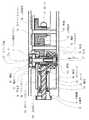
続いて、カートリッジホルダ接合部200について説明する。
カートリッジホルダ接合部200は、図5で示すように、着脱リング38、第1ボール39a、第2ボール39b、着脱リング付勢ばね40、押し子付勢ばね41、ばね収容部42、連結リング43、ストッパ44、ボールプッシャ45、ボールプッシャ付勢ばね46を備えている。
【0046】
続いて、更に詳細な機構および取り付け・取り外し動作について図6,図7を参照しつつ説明する。まず、カートリッジホルダ300が接合されていない状態のカートリッジ接合部200の状態を図6(a)で示す。この図に示すように、連結リング43は、第1ボール39aおよび第2ボール39bを収容するようになされている。なお、第2ボール39bが筒内へ移動しないように配慮(例えば第2ボール39bの配置孔が円錐台形状に形成)されている。
【0047】
ボールプッシャ45は、ボールプッシャ付勢ばね46の付勢力により矢印c方向に付勢されている。ボールプッシャ45は、多段状外周面を有する円筒体であり、詳しくは図6(a)のように、径が小さい下段部と径が大きい上段部という二段の段部を有するような形状である。
同様に、着脱リング38は、連結リング43のばね収容部42に収容される着脱リング付勢ばね40の付勢力により矢印c方向に付勢されている。着脱リング38は、溝付き内周面を有する円筒体であり、詳しくは溝部38a,38bを有している。
【0048】
この状態ではボールプッシャ45の多段状外周面の上段部に当接する第1ボール39aが着脱リング38の溝部38aに入り込み、しかも着脱リング38は着脱リング付勢ばね40により矢印c方向に押圧され、また、ボールプッシャ45もボールプッシャ付勢ばね46により矢印c方向に押圧され、着脱リング38および第1ボール39aともに確実に移動拘束されている。
【0049】
このような状態のカートリッジホルダ接合部200に、図6(b)で示すように、1.0mlまたは1.8mlのカートリッジ500が既に組み込まれたカートリッジホルダ300が矢印d方向(図5では矢印b方向)に挿入され、ボールプッシャ45に接触するまで到達したものとする(図6(b)はこの状態を示す)。
このカートリッジホルダ300は、円環状の溝部300aが外周面に設けられた溝付き外周面を有している。この溝部300aの中にはリング状のステップ部300bが収容されている。
【0050】
そして、図6(c)で示すように、カートリッジホルダ300がさらに矢印e方向に挿入されると、ボールプッシャ付勢ばね46の付勢力に抗しつつ、ボールプッシャ45も矢印e方向に押送される。これにより、第1ボール39aとボールプッシャ45の多段形状外周面との間に移動可能な隙間が、および、第2ボール39bの直下に溝部300aが位置し、さらに着脱リング付勢ばね40により矢印f方向に付勢されている着脱リング38が第1ボール39aを矢印g1方向に押しているため第1ボール39aは矢印h1方向に移動し、また、着脱リング38が第2ボール39bを矢印g2方向に押しているため第2ボール39bは矢印h2方向に移動する。
【0051】
そして、図6(d)で示すように、着脱リング38がさらに矢印i方向に移動するが、ストッパ44に当接して移動が拘束され、図6(d)で示す状態で安定する。この場合、大きな機械音がするため、操作者はカートリッジホルダ300が接合されたことを判別できる。
接合終了後、第1ボール39aは、着脱リング38およびボールプッシャ45の多段状外周面の下段部と接し、また、第2ボール39bは、着脱リング38および溝部300aと当接することでカートリッジホルダ300はカートリッジホルダ接合部200で強固に固定される。
このように、カートリッジ500およびカートリッジホルダ300をカートリッジ接合部200に挿入すると、自動的に固定されるため、取り付けは極めて容易である。
【0052】
さらに、カートリッジ500およびカートリッジホルダ300をカートリッジ接合部200から引き抜いて取り外す場合は、図7(a)で示すように、操作者が着脱リング付勢ばね40の付勢力に抗しつつ、着脱リング38を矢印j方向に移動させる。
さらに押圧して最終的に、図7(b)で示す状態まで着脱リング38を移動させると、第1ボール39aの直上に溝部38aが、また、第2ボール39bの直上に溝部38bがそれぞれ位置することとなる。このとき、ボールプッシャ付勢ばね46により矢印k方向にボールプッシャ45およびカートリッジホルダ300が付勢されており、このようなボールプッシャ45は第1ボール39aを矢印l1方向に押しているため第1ボール39aは矢印m1方向に移動し、また、カートリッジホルダ300のステップ部300bが第2ボール39bを矢印l2方向に押しているため第2ボール39bは矢印m2方向に移動する。
【0053】
そして、図7(c)で示すようにボールプッシャ45はさらに矢印n方向に移動して第1ボール39aを矢印o方向に押し上げると着脱リング38も第1ボール39aにより移動が拘束され、さらにボールプッシャ45が第1ボール39aを押圧した状態でボールプッシャ45の多段状外周面の上段に第1ボール39aが当接した状態で移動停止する。この状態でカートリッジ500およびカートリッジホルダ300は引き抜き自在となる。
最終的にカートリッジホルダ300を外し、図7(d)のような状態となる。なお、この状態は図6(a)の状態と同じである。
カートリッジ500およびカートリッジホルダ300のカートリッジホルダ接合部200への着脱はこのようなものである。
【0054】
なお、カートリッジには麻酔薬1.0mlおよび麻酔薬1.8mlという長さが異なる二種類のカートリッジがある。カートリッジホルダ300に何れのカートリッジ500が取り付ける場合であっても、ロック解除ボタン4を押下して押し子21を移動自在にした状態でカートリッジ500を取り付ければ、押し子付勢ばね41により押し子21がゴム栓501に接触した状態を維持しつつ移動が進み、最終的にゴム栓501に一定圧で当接した状態で取り付けが完了するため、カートリッジ500の長さに拘わらず使用することができる。
このようにして、麻酔薬1.0mlおよび麻酔薬1.8mlという長さが異なる2種類のカートリッジを使用することができる。
【0055】
続いて、このような電動注射器の操作・動作について説明する。
図示しない充電器に載置されている電動注射器を取り上げて、操作表示部9の電源スイッチを押下して電源を入れる。この場合、操作表示部9のバッテリー残量表示は、充電が完了している旨表示される。
【0056】
この電動注射器では、図8で示すように、複数(図8では三種類)の注入速度を選択することができる。
操作表示部9の速度設定スイッチを押下して速度設定表示を確認しつつ所望の注入速度を選択する。
【0057】
続いて、麻酔薬1.0mlおよび麻酔薬1.8mlという長さが異なる2種類のカートリッジのうち、何れかのカートリッジ500をカートリッジホルダ300に装填する。
カートリッジホルダ300を電動注射器にセットするとき、まずロック解除ボタン4を押下してクラッチ機構部により伝達機構部の伝達を切断した状態とし、押し子21を、カートリッジホルダ接合部200の中まで押圧して移動させておく。
【0058】
さらに、ロック解除ボタン4を押下して伝達機構部の伝達を切断した状態で、カートリッジホルダ300を取り付ける。この場合、図5で示すように、カートリッジ500のゴム栓501に接触する押し子21が本体部100側へ押圧移動させられる際に、押し子付勢ばね41のばね力により一定圧力で接触した状態を維持しつつ、最終的にスタート位置まで移動することとなる。
そして、先に説明したような操作を行ってカートリッジホルダ300をカートリッジホルダ接合部200に固定し、図5で示すような状態とする。そして、歯科用注射針400を取り付けて、初期作業を完了する。
【0059】
続いて、電動注射器を握持すると、光反射式センサであるセーフティセンサ6の窓穴部が遮蔽されて操作入力が行われる。そして、この状態で光反射式センサであるスタート/ストップセンサ7の窓穴部を人差し指で遮蔽して操作入力を行う。このように、セーフティセンサ6とスタート/ストップセンサ7とが共に遮蔽されて操作された場合のみ、制御基板8は、麻酔薬の注入動作を開始するように駆動モータ12を制御するため、何れか一方を誤って遮蔽したような場合であっても誤動作することがなくなる。
【0060】
なお、セーフティセンサ6とスタート/ストップセンサ7とは、光反射式センサであって、窓穴部を覆うのみであるため、電動注射器の移動を防止し、痛みの原因となる針先のブレを減少させることもできる。
このようにして電動注射器を操作し、針内の空気抜きのため、歯科用注射針400の針先まで麻酔薬を到達させつつ、電動注射器の動作を確認する。
【0061】
続いて、歯科用注射針400を歯肉等に刺し入れて、スタート/ストップセンサ7を遮蔽して注射を開始する。この時、制御基板8の図示しない再生部が、ブザー音またはメロディ音楽を再生する。このようなブザー音またはメロディ音楽により麻酔薬の注入動作中であることを認知させることができ、また、患者にとっては安心感を抱かせることが可能となる。
【0062】
また、制御基板8は、図8で示すように、注入当初は麻酔薬の注入量が微量となるように小さい注入速度から開始し、そして略一定変化率で注入速度を増加させ、所定期間経過後は一定の注入速度となるように、駆動モータ12を駆動させて伝達機構部を介して押し子21の移動量を制御する。
【0063】
このように注入速度を最初は小さくすることで、注射当初に感じる痛みを低減させて、患者にとっては安心感を抱かせることが可能となる。
そして、所定量の注入後にスタート/ストップセンサ7を遮蔽する人差し指を移動させて注入動作を終了させる。
電動注射器の操作・動作はこのようなものである。
【0064】
【発明の効果】
本発明によれば、注入当初の注入量を少なくする注入速度の制御、ブザー音・メロディ音楽による患者への配慮、注入操作時の針先の移動の防止を実現したため、患者が痛みを感じないように操作性を向上させた電動注射器を提供することができる。
【0065】
また、セーフティセンサおよびスタート/ストップセンサをともに操作入力して初めて注入動作を行うようにしたため、光反射式センサのように遮蔽のみで容易に操作入力されるスイッチを用いることが可能となり、誤動作の防止・操作性の向上を共に実現することができる。
【0066】
また、クラッチ機構を設けて伝達機構部のクラッチ動作を可能として押し子を移動可能とし、さらに押し子を押し子付勢用ばねで付勢することで、1.0ml用カートリッジまたは1.8ml用カートリッジを、カートリッジホルダを交換することなく共用でき、セット位置では麻酔薬のゴム栓に押し子用ラックが一定圧で接触しているような電動注射器を提供することができる。
【0067】
また、カートリッジホルダ接合部における接合は、カートリッジが組み付けられたカートリッジホルダを挿入するだけで自動的に取り付けが行われるため、取り扱いが容易である。
【0068】
総じて、全体的な操作性を向上させて、歯科医師および患者にとって信頼性が高い歯科治療麻酔薬用電動注射器を提供することができる。
【図面の簡単な説明】
【図1】歯科治療麻酔薬用電動注射器の外観を説明する外観図である。
【図2】歯科治療麻酔薬用電動注射器の外観を説明する外観図である。
【図3】歯科治療麻酔薬用電動注射器の内部を説明する内部機構図である。
【図4】クラッチ機構部を説明する内部機構図である。
【図5】カートリッジホルダ接合部を説明する内部機構図である。
【図6】カートリッジホルダ接合部の動作を説明する動作説明図である。
【図7】カートリッジホルダ接合部の動作を説明する動作説明図である。
【図8】注入速度制御を説明する説明図である。
【符号の説明】
100 本体部
200 カートリッジホルダ接合部
300 カートリッジホルダ
300a 溝部
300b ステップ部
400 歯科用注射針
500 カートリッジ
1,2 カバーケース
3 天板
4 ロック解除ボタン
5 動作確認ランプ
6 セーフティセンサ
7 スタート/ストップセンサ
8 制御基板
9 操作表示部
10 充電池
11 充電基板
12 駆動モータ
13 平歯車
14 アイドラ歯車
15 平歯車
16 ベベルギア
17 ベベルギア
17a 筒部
18 平歯車
19 二段歯車
20 二段歯車
21 押し子
21a ラック
22 ギヤケース
23 軸
24 回転軸
24a 止めねじ
25 ガイド
26 軸受
27 クラッチ軸
27a 穴
28,29 軸部
30,34 ギヤケースカバー
31,32 軸受ブシュ
33 軸受
35 軸受
36 軸受
37 ばね
38 着脱リング
38a,38b 溝部
39a 第1ボール
39b 第2ボール
40 着脱リング付勢ばね
41 押し子付勢ばね
42 ばね収容部
43 連結リング
44 ストッパ
45 ボールプッシャ
46 ボールプッシャ付勢ばね[0001]
BACKGROUND OF THE INVENTION
The present invention relates to an electric syringe for dental anesthetic used for injecting an anesthetic in dental treatment.
[0002]
[Prior art]
There is a hand-operated syringe that is commonly used as a tool for injecting anesthetics in dental treatment, but the anesthetic injection needle uses a very fine needle, so the pressure when injecting is large, Maintaining a constant infusion rate required great effort. For this reason, electric syringes for dental treatment anesthetics (hereinafter simply abbreviated as electric syringes in the description of the prior art) for reducing the burden of dental treatment are becoming widespread.
[0003]
As a conventional technique of such an electric syringe, for example, “a dental electric syringe” (see Patent Document 1), “a dental electric injection device” (see Patent Document 2), or “a receptacle in a dental cartridge type injection device” Is known "(see Patent Document 3).
[0004]
[Patent Document 1]
JP-A-7-213610
[Patent Document 2]
JP 2001-70444 A
[Patent Document 3]
JP 2002-191694 A
[0005]
[Problems to be solved by the invention]
The electric syringes that are the inventions described in these
In addition, it is necessary to press the operation button with your finger to start injecting the anesthetic from the electric syringe, but there is a problem that the patient feels pain because the vibration is transmitted to the electric syringe during operation and the needle moves. .
Further, consideration has been required for this operation button to suppress malfunction.
[0006]
Furthermore, there are currently two types of anesthetic drugs, a 1.0 ml cartridge and a 1.8 ml cartridge, but conventional electric syringes deal with this by replacing the cartridge holder that holds the cartridge. It was.
However, it is not preferable to use a plurality of types of cartridge holders while exchanging them because it leads to complicated management, and there has been a demand for making the cartridge holders common.
In addition, a mechanism for easily attaching such a cartridge holder has been required.
[0007]
The present invention has been made to solve the above-mentioned problems, and the first object thereof is to improve operability so that the patient does not feel pain and to relieve the pain experienced by the patient. The object is to provide an electric syringe that can be considered together.
[0008]
In addition, since the second purpose is an operation that requires the careful operation of drug injection, there has been a request to reliably avoid an operation that does not match the will of the operating dentist. For this reason, it is providing the electric syringe which prevents a malfunctioning.
[0009]
Furthermore, as a third purpose, the cartridge for 1.0 ml or the cartridge for 1.8 ml can be shared without exchanging the cartridge holder. At the set position, the pusher rack contacts the rubber stopper of the anesthetic agent at a constant pressure. It is to provide an electric syringe like this.
[0010]
Furthermore, as a fourth object, a joining mechanism for making it possible to share a 1.0 ml cartridge or a 1.8 ml cartridge is necessary. An object of the present invention is to provide an electric syringe including a cartridge holder joining portion which is a simple mechanism that can be firmly joined only by a cartridge holder.
[0011]
In general, it is an object of the present invention to provide an electric syringe for dental anesthesia that is highly reliable for dentists and patients by improving the overall operability.
[0012]
[Means for Solving the Problems]
In order to solve the above problems, an electric syringe for dental anesthetics according to
In the electric syringe for dental treatment anesthesia that pushes and moves the rubber stopper of the cartridge containing the anesthetic to flow the anesthetic into the dental injection needle and discharges the anesthetic from the needle tip,
A pusher for pressing and moving the rubber stopper of the cartridge;
A transmission mechanism for transmitting driving force to the pusher;
A drive motor for applying a driving force to the transmission mechanism,
A playback unit that outputs buzzer sounds and / or melody music;
The operation part of the light reflection type sensor that performs the operation of injecting operation by covering the window hole part,
Connected to the playback unit, operation unit, and drive motor,A control unit for controlling the drive motor;
With
The control unitIn response to the operation of starting the injection operation from the operation unit, the drive motor is driven to start injection,The injection speed is increased at the beginning of injection, and the amount of movement of the pusher is controlled by driving the drive motor so that the injection speed becomes constant after a predetermined period.At the same time, the playback unit is controlled to output a buzzer sound and / or a melody music during the anesthetic injection operation.It is characterized by that.
[0015]
These claims1In such an invention, consideration has been given to relieve pain of a patient undergoing dental treatment, and the first object is achieved.
[0016]
Further, the claims of the present invention2The electric syringe for dental treatment anesthetics of the invention according to
Claim1In the electric syringe for dental treatment anesthesia as described,
The operation unit is
A first operation part of a light-reflective sensor that inputs an operation by covering a window hole with a hand holding an electric syringe for dental treatment anesthetic;
A second operation portion of the light reflection type sensor that inputs an operation by covering the window hole with a finger;
With
The control unit is characterized in that the injection operation is performed only when the first operation unit and the second operation unit are operated together to prevent malfunction.
[0017]
These claims2In the invention according to the present invention, since the operation input is made simply by shielding with a finger called a reflection type optical sensor, the operation input is not made simple by using two operation portions, and a treatment error by a dentist who performs treatment is prevented. The second objective is achieved.
[0018]
Further, the claims of the present invention3The electric syringe for dental treatment anesthetics of the invention according to
Claim1 or claim 2In the electric syringe for dental treatment anesthetic described in
The transmission mechanism is
An unlock button provided on the cover case;
A clutch mechanism for releasing transmission by the transmission mechanism when the lock release button is pressed;
With
You can move by pressing the pusher while pressing the unlock button and the clutch mechanism cuts off the transmission of the transmission mechanism.RuThen, the lock release button is released and the transmission of the transmission mechanism unit is connected by the clutch mechanism unit.
[0019]
Moreover, the electric syringe for dental treatment anesthetics of the invention according to claim 4 of the present invention,
The electric syringe for dental anesthetics according to claim 3,
Anesthetic 1.0mlOrTwo cartridges with different lengths of 1.8 ml of anestheticOne of the cartridges selected fromOne cartridge holder to hold,
When setting the cartridge holder in the electric syringe for dental treatment anesthesia, press the unlock button to turn off the transmission of the transmission mechanism by the clutch mechanism, and move the pusher while in contact with the rubber plug of the cartridge. However, the cartridge holder is attached, and the pusher becomes a start position in a state in which the pusher comes into contact with the rubber stopper at a constant pressure by a spring force.
[0020]
These claims3, 4In the invention according to the present invention, the pusher can be moved by the clutch mechanism, and even when the cartridge has a different length, the pusher at the start of injection is in the optimum position and contacts while pressing the rubber stopper at a constant pressure. And achieve the third objective.
[0021]
Further, the claims of the present invention5The electric syringe for dental treatment anesthetics of the invention according to
A cartridge holder joint to which a cartridge holder having a grooved outer peripheral surface is joined,
A coupling ring including a rotating body-shaped cylinder;
A ball pusher biasing spring disposed in the cylinder of the coupling ring;
A ball pusher which is in a cylinder of the coupling ring and is urged in a direction opposite to the insertion direction of the cartridge holder by a ball pusher urging spring and having a multistage outer peripheral surface;
A detachable ring biasing spring disposed outside the cylinder of the connecting ring;
A detachable ring which is outside the connecting ring and is a cylindrical body having a grooved inner peripheral surface which is urged in a direction opposite to the insertion direction of the cartridge holder by a detachable ring urging spring;
A first ball disposed on the connecting ring so as to move between the multi-step outer peripheral surface of the ball pusher and the grooved inner peripheral surface of the detachable ring;
A second ball disposed on the coupling ring so as to move between the grooved outer peripheral surface of the joined cartridge holder and the grooved inner peripheral surface of the detachable ring;
With
When the cartridge holder is inserted, the cartridge holder presses the ball pusher and the cartridge holder and the ball pusher move in conjunction with each other, whereby the first ball is moved to the ball pusher side and the second ball is moved to the cartridge holder. And the detachable ring released from the movement restraint by the first ball moves in the direction opposite to the cartridge insertion direction to press the first ball and the second ball, thereby joining the cartridge holder. And
[0022]
These claims5In the invention according to the fourth aspect, even if the cartridges have different lengths, the fourth object is achieved by relying only on the cartridge holder to be firmly and automatically joined.
[0023]
DETAILED DESCRIPTION OF THE INVENTION
Next, an embodiment relating to an electric syringe for dental anesthesia of the present invention (hereinafter simply abbreviated as an electric syringe in the description of embodiments of the invention) will be described with reference to the drawings. 1 and 2 are external views illustrating the external appearance of the electric syringe, FIG. 3 is an internal mechanism diagram illustrating the inside of the electric syringe, FIG. 4 is an internal mechanism diagram illustrating the clutch mechanism, and FIG. 5 is a cartridge holder joint. FIG. 6 and FIG. 7 are operation explanatory views for explaining the operation of the cartridge holder joint portion, and FIG. 8 is an explanatory view for explaining the injection speed control. If FIG. 2 is a front view, FIG. 1 has a relationship of a right side view.
[0024]
The electric syringe includes a main body 100 (see FIGS. 1 and 2), a cartridge holder joint 200 (see FIGS. 1 and 3), a cartridge holder 300 (see FIGS. 1 and 3), and a dental injection needle 400 (see FIG. 1). , FIG. 3), and cartridge 500 (see FIG. 3).
[0025]
The main body 100 is formed by combining the
[0026]
As shown in FIG. 3, an operation display unit 9 is provided on the upper side of a control board 8 which is a specific example of the control unit, and a display panel on which a display and operation symbols are printed is pasted on the front side. The display panel 9 is provided with a battery remaining amount display portion, a speed setting display portion, a power switch, and a speed setting switch.
The operation check lamp 5 also receives power supply via the control board 8 and blinks so that it can be visually confirmed that it is operating.
[0027]
As shown in FIG. 2, two
[0028]
Next, the internal structure will be described.
First, a drive motor 12 is provided as shown in FIG.
The drive motor 12 is connected to a part of the control drive circuit of the control board 8 and is configured to control the drive force. Note that how the drive is controlled will be described later.
The drive motor 12 will apply a driving force to the transmission mechanism. A spur gear 13 is pivotally supported on the main shaft of the drive motor 12.
[0029]
The transmission mechanism is a general term for a gear train that transmits the driving force applied from the drive motor 12 via the spur gear 13, and is an idler gear 14, a spur gear 15, a bevel gear 16, a bevel gear 17, a spur gear 18, a two-stage gear. A
The two-
[0030]
The drive motor 12 and the transmission mechanism are housed in a gear case 22. The gear case 22 is held and fixed to a positioning boss (convex shape) inside the
[0031]
Next, the transmission operation of the transmission mechanism unit will be described.
The idler gear 14 is rotatably supported on a shaft 23 fixed to the gear case 22 and meshes with the spur gear 13. A driving force is transmitted from the spur gear 13 to the idler gear 14.
[0032]
As shown in FIGS. 3 and 4, the spur gear 15 is pivotally fixed to the rotary shaft 24 by a set screw 24a. The rotary shaft 24 is pivotally fixed to an inner ring of two bearings 26 in which an outer ring is held by a guide 25 and is rotatable.
The spur gear 15 meshes with the idler gear 14, and the driving force is transmitted from the idler gear 14 to the spur gear 15. The driving force of the spur gear 15 is transmitted to the bevel gear 16 through the rotating shaft 24.
[0033]
The bevel gear 16 meshes with the bevel gear 17, and the driving force is transmitted from the bevel gear 16 to the bevel gear 17. These bevel gears 16 and 17 convert the driving force transmission direction by approximately 90 °.
[0034]
A clutch shaft 27 is inserted into the bevel gear 17. The cross section of the clutch shaft 27 has a structure such as a spline shaft or a serration shaft (hereinafter referred to as a sliding groove), and the clutch shaft 27 has a sliding hole of the bevel gear 17 that coincides with such a sliding groove. And is slidably attached.
A spur gear 18 is also inserted through the clutch shaft 27. The spur gear 18 is also provided with a sliding hole that matches the sliding groove of the clutch shaft 27, and the clutch shaft 27 is fitted on the spur gear 18 that matches the sliding groove and is slidably attached. ing.
[0035]
The bevel gear 17 and the spur gear 18 are apparently two-stage gears. The bevel gear 17 corresponds to the large gear portion, and the spur gear 18 corresponds to the small gear portion.
The driving force transmitted to the bevel gear 17 is transmitted to the spur gear 18 via the clutch shaft 27.
[0036]
The two-
The two-
[0037]
The rack 21a formed on the pusher 21 further meshes with the small gear portion of the two-
The moving direction of the pusher 21 is constrained by the bearing bushes 31 and 32 shown in FIG. The driving force transmitted to the rack 21a of the pusher 21 moves to the left so as to press the rubber plug 501 (see FIG. 5) of the cartridge 500.
In this case, the gear train of the transmission mechanism part is greatly decelerated and moves sufficiently slower than the rotation of the drive motor 12, so that the minimum unit of the injection amount can be reduced.
[0038]
As shown in FIG. 4, this transmission mechanism includes a clutch mechanism that releases transmission of the drive motor 12.
The clutch mechanism portion includes a bevel gear 17, a spur gear 18, a clutch shaft 27, and a spring 37.
[0039]
Since only the sliding groove of the clutch shaft 27 is inserted into the sliding hole of the bevel gear 17 described above, the clutch shaft 27 can slide in the axial direction. The bevel gear 17 is fixed to the inner ring of the bearing 33 whose outer ring is held by the gear case 22 so as to rotate only.
[0040]
The clutch shaft 27 is slidably fixed to the inner ring of a bearing 35 whose outer ring is held by the gear case cover 34. The presence of the bearings 33 and 35 makes the clutch shaft 27 rotatable, and the bevel gear 17, the spur gear 18 and the clutch shaft 27 rotate integrally and stably by fitting the sliding groove and the sliding hole. To do.
In addition, a sliding groove is fitted into the sliding hole so that the clutch shaft 27 can slide up and down. The clutch shaft 27 slides along the sliding holes of the bevel gear 17 and the spur gear 18.
[0041]
The lock release button 4 is pivotally supported on the clutch shaft 27 via a bearing 36 so that the lock release button 4 does not rotate even when the clutch shaft 27 rotates.
A hole 27a is provided below the clutch shaft 27, and the bevel gear 17 is formed with a cylindrical tube portion 17a. A spring 37 is disposed in the hole 27a and the tube portion 17a. . Normally, the clutch shaft 27 is urged in the direction of arrow a shown in FIG. 4 and is stabilized in a state of being positioned on the upper side as shown in FIG.
[0042]
Thus, when the lock release button 4 is in the upper position, the sliding holes of the bevel gear 17 and the spur gear 18 are both engaged with the sliding groove of the clutch shaft 27, and the driving force is transmitted to the bevel gear 17. And transmitted to the spur gear 18 via the clutch shaft 27. Normally, the bevel gear 17, the clutch shaft 27, and the sliding grooves and holes of the gear 18 are engaged with each other so that the driving force due to the rotation of the driving motor can be transmitted.
[0043]
On the other hand, when the lock release button 4 is pressed and positioned at the lower side (not shown), the sliding groove of the clutch shaft 27 is engaged with only the sliding hole of the bevel gear 17 and the sliding hole of the spur gear 18 is engaged. Then, even if the driving force is transmitted to the bevel gear 17, it is transmitted to the clutch shaft 27 but is not transmitted to the spur gear 18, and the transmission of the driving force in the transmission mechanism is released.
[0044]
In this way, the transmission mechanism portion can be moved by pressing the pusher 21 in a state where the lock release button 4 is pressed and the transmission of the transmission mechanism portion is cut by the clutch mechanism portion, and the lock release button 4 is released. The transmission of the transmission mechanism unit can be connected by the clutch mechanism unit.
[0045]
Next, the cartridge holder joint 200 will be described.
As shown in FIG. 5, the cartridge holder joint portion 200 includes a
[0046]
Next, a more detailed mechanism and attachment / removal operation will be described with reference to FIGS. First, FIG. 6A shows a state of the cartridge joint portion 200 in a state where the
[0047]
The
Similarly, the
[0048]
In this state, the
[0049]
As shown in FIG. 6B, the
The
[0050]
As shown in FIG. 6C, when the
[0051]
Then, as shown in FIG. 6D, the
After the joining is completed, the
Thus, since the cartridge 500 and the
[0052]
Further, when the cartridge 500 and the
When the
[0053]
Then, as shown in FIG. 7C, when the
Finally, the
The attachment and detachment of the cartridge 500 and the
[0054]
There are two types of cartridges with different lengths of 1.0 ml of anesthetic and 1.8 ml of anesthetic. Regardless of which cartridge 500 is attached to the
In this way, two types of cartridges having different lengths of 1.0 ml of anesthetic and 1.8 ml of anesthetic can be used.
[0055]
Next, the operation / operation of such an electric syringe will be described.
Taking up an electric syringe placed on a charger (not shown), the power switch of the operation display unit 9 is pressed to turn on the power. In this case, the battery remaining amount display on the operation display unit 9 indicates that charging is complete.
[0056]
In this electric syringe, as shown in FIG. 8, a plurality of (three types in FIG. 8) injection speeds can be selected.
A desired injection speed is selected while confirming the speed setting display by depressing the speed setting switch of the operation display unit 9.
[0057]
Subsequently, one of the two cartridges having different lengths of 1.0 ml of anesthetic and 1.8 ml of anesthetic is loaded into the
When the
[0058]
Further, the
Then, the operation as described above is performed to fix the
[0059]
Subsequently, when the electric syringe is gripped, the window hole portion of the safety sensor 6 that is a light reflection sensor is shielded and an operation input is performed. In this state, the window hole portion of the start / stop sensor 7 which is a light reflection type sensor is shielded with an index finger to perform an operation input. Thus, only when the safety sensor 6 and the start / stop sensor 7 are both shielded and operated, the control board 8 controls the drive motor 12 to start the anesthetic injection operation. Even if one of them is shielded by mistake, it will not malfunction.
[0060]
Note that the safety sensor 6 and the start / stop sensor 7 are light-reflective sensors and only cover the window hole, so that the electric syringe is prevented from moving and the needle tip that causes pain is shaken. It can also be reduced.
The electric syringe is operated in this way, and the operation of the electric syringe is confirmed while allowing the anesthetic to reach the needle tip of the
[0061]
Subsequently, the
[0062]
Further, as shown in FIG. 8, the control board 8 starts from a small injection rate so that the injection amount of the anesthetic becomes a very small amount at the beginning of the injection, and increases the injection rate at a substantially constant change rate, and a predetermined period of time elapses. Thereafter, the drive motor 12 is driven to control the amount of movement of the pusher 21 via the transmission mechanism so that the injection rate is constant.
[0063]
Thus, by reducing the injection speed at the beginning, it is possible to reduce the pain felt at the beginning of the injection and to give the patient a sense of security.
Then, after the predetermined amount of injection, the index finger that shields the start / stop sensor 7 is moved to end the injection operation.
The operation / operation of the electric syringe is like this.
[0064]
【The invention's effect】
According to the present invention, control of the injection speed to reduce the initial injection volume, consideration for the patient by buzzer sound and melody music, prevention of movement of the needle tip during the injection operation, the patient does not feel pain Thus, an electric syringe with improved operability can be provided.
[0065]
In addition, since the injection operation is performed only after the safety sensor and the start / stop sensor are both operated and input, it is possible to use a switch that is easily operated and input only by shielding, such as a light-reflective sensor. Both prevention and improvement in operability can be realized.
[0066]
In addition, a clutch mechanism is provided to enable the clutch operation of the transmission mechanism portion so that the pusher can be moved. Further, the pusher is urged by a pusher urging spring, whereby the cartridge for 1.0 ml or 1.8 ml is used. It is possible to provide an electric syringe in which the cartridge can be shared without exchanging the cartridge holder, and the pusher rack is in contact with the rubber stopper of the anesthetic agent at a constant pressure at the set position.
[0067]
In addition, the joining at the cartridge holder joining portion is easy to handle because the attachment is automatically performed simply by inserting the cartridge holder in which the cartridge is assembled.
[0068]
In general, it is possible to provide an electric syringe for dental anesthesia that is highly reliable for dentists and patients with improved overall operability.
[Brief description of the drawings]
FIG. 1 is an external view for explaining the external appearance of an electric syringe for dental anesthetics.
FIG. 2 is an external view illustrating the external appearance of an electric syringe for dental anesthetics.
FIG. 3 is an internal mechanism diagram for explaining the inside of the electric syringe for dental anesthetics.
FIG. 4 is an internal mechanism diagram illustrating a clutch mechanism.
FIG. 5 is an internal mechanism diagram illustrating a cartridge holder joint portion.
FIG. 6 is an operation explanatory view for explaining the operation of the cartridge holder joining portion.
FIG. 7 is an operation explanatory view for explaining the operation of the cartridge holder joining portion.
FIG. 8 is an explanatory diagram for explaining injection rate control.
[Explanation of symbols]
100 Body
200 Cartridge holder joint
300 Cartridge holder
300a Groove
300b step part
400 Dental needle
500 cartridges
1, 2 Cover case
3 Top plate
4 Unlock button
5 Operation check lamp
6 Safety sensor
7 Start / stop sensor
8 Control board
9 Operation display
10 Rechargeable battery
11 Charging board
12 Drive motor
13 Spur gear
14 idler gears
15 Spur gear
16 Bevel Gear
17 Bevel Gear
17a Tube part
18 Spur gear
19 Double gear
20 Double gear
21 Pusher
21a rack
22 Gear case
23 axes
24 Rotating shaft
24a Set screw
25 Guide
26 Bearing
27 Clutch shaft
27a hole
28, 29 Shaft
30, 34 Gear case cover
31, 32 Bearing bush
33 Bearing
35 Bearing
36 Bearing
37 Spring
38 Detachable ring
38a, 38b groove
39a first ball
39b second ball
40 Detachable ring biasing spring
41 Pusher biasing spring
42 Spring housing
43 Connecting ring
44 Stopper
45 ball pusher
46 Ball pusher biasing spring
Claims (5)
Translated fromJapaneseカートリッジのゴム栓を押圧移動させる押し子と、
押し子に駆動力を伝達する伝達機構部と、
伝達機構部に駆動力を付与する駆動モータと、
ブザー音および/またはメロディ音楽を出力する再生部と、
注入動作開始の操作を、窓穴部を覆うことで行う光反射式センサの操作部と、
再生部、操作部、および、駆動モータと接続され、駆動モータを制御する制御部と、
を備え、
制御部は、操作部からの注入動作開始の操作を受けて駆動モータを駆動させて注入を開始し、注入当初は注入速度を増加させ、所定期間経過後は一定の注入速度となるように、駆動モータを駆動して押し子の移動量を制御するとともに、麻酔薬の注入動作中にブザー音および/またはメロディ音楽を出力するように再生部を制御することを特徴とする歯科治療麻酔薬用電動注射器。In the electric syringe for dental treatment anesthesia that pushes and moves the rubber stopper of the cartridge containing the anesthetic to flow the anesthetic into the dental injection needle and discharges the anesthetic from the needle tip,
A pusher for pressing and moving the rubber stopper of the cartridge;
A transmission mechanism for transmitting driving force to the pusher;
A drive motor for applying a driving force to the transmission mechanism,
A playback unit that outputs buzzer sounds and / or melody music;
The operation part of the light reflection type sensor that performs the operation of injecting operation by covering the window hole part,
A control unit that is connected to the reproduction unit, the operation unit, and the drive motor and controls the drive motor;
With
The control unit starts the injection by driving the driving motor in response to the operation of starting the injection operation from the operation unit, increases the injection speed at the beginning of injection, and becomes a constant injection speed after a predetermined period of time, An electric motor for dental treatment anesthesia characterized by controlling a moving amount of a pusher by driving a drive motor and controlling a reproducing unit so as to output a buzzer sound and / or a melody music during an anesthetic injection operation. Syringe.
前記操作部は、
歯科治療麻酔薬用電動注射器を把持する手で窓穴部を覆って操作入力する光反射式センサの第1操作部と、
指で窓穴部を覆って操作入力する光反射式センサの第2操作部と、
を備えるものとし、
制御部は、第1操作部および第2操作部を共に操作する場合のみ注入動作を行うようにして誤動作を防止することを特徴とする歯科治療麻酔薬用電動注射器。The electric syringe for dental anesthesia according to claim 1,
The operation unit is
A first operation part of a light-reflective sensor that inputs an operation by covering a window hole with a hand holding an electric syringe for dental treatment anesthetic;
A second operation portion of the light reflection type sensor that inputs an operation by covering the window hole with a finger;
With
The control unit is configured to perform an injection operation only when both the first operation unit and the second operation unit are operated, thereby preventing a malfunction.
前記伝達機構部は、
カバーケースに設けられるロック解除ボタンと、
ロック解除ボタンが押下されたときに伝達機構部による伝達を解放するクラッチ機構部と、
を備え、
ロック解除ボタンを押下してクラッチ機構部により伝達機構部の伝達を切断した状態で押し子を押圧して移動できるようにし、ロック解除ボタンを解放してクラッチ機構部により伝達機構部の伝達を繋げることを特徴とする歯科治療麻酔薬用電動注射器。In the electric syringe for dental treatment anesthetics according to claim 1 or claim 2,
The transmission mechanism is
An unlock button provided on the cover case;
A clutch mechanism for releasing transmission by the transmission mechanism when the lock release button is pressed;
With
Press the lock release button so that the clutch mechanism can cut the transmission of the transmission mechanism so that it can be moved by pressing the pusher, release the lock release button and connect the transmission of the transmission mechanism with the clutch mechanism An electric syringe for dental treatment anesthetics.
麻酔薬1.0mlまたは麻酔薬1.8mlという長さが異なる2種類のカートリッジから選択された何れか一方のカートリッジを保持する1つのカートリッジホルダとし、
カートリッジホルダを歯科治療麻酔薬用電動注射器にセットするとき、ロック解除ボタンを押下してクラッチ機構部により伝達機構部の伝達を切断した状態とし、カートリッジのゴム栓に接触した状態で押し子を移動しつつカートリッジホルダが取り付けられ、ばね力により押し子がゴム栓に一定圧力で接触した状態のスタート位置となることを特徴とする歯科治療麻酔薬用電動注射器。The electric syringe for dental anesthetics according to claim 3,
One cartridge holderfor holdingany one cartridgeselected from two types of cartridges having different lengths of 1.0 ml of anestheticor 1.8 ml of anesthetic,
When setting the cartridge holder in the electric syringe for dental treatment anesthesia, press the unlock button to turn off the transmission of the transmission mechanism by the clutch mechanism, and move the pusher while in contact with the rubber plug of the cartridge. An electric syringe for dental anesthesia, wherein the cartridge holder is attached and the pusher is in a starting position in contact with the rubber stopper at a constant pressure by a spring force.
溝付き外周面を有するカートリッジホルダが接合されるカートリッジホルダ接合部は、
回転体形状の筒体を含む連結リングと、
連結リングの筒内に配置されるボールプッシャ付勢ばねと、
連結リングの筒内にあって、ボールプッシャ付勢ばねによりカートリッジホルダの挿入方向と反対方向に付勢され、多段状外周面を有する円筒体であるボールプッシャと、
連結リングの筒外に配置される着脱リング付勢ばねと、
連結リングの筒外にあって、着脱リング付勢ばねによりカートリッジホルダの挿入方向と反対方向に付勢され、溝付き内周面を有する円筒体である着脱リングと、
ボールプッシャの多段状外周面と着脱リングの溝付き内周面との間を移動するように、連結リングに配置される第1ボールと、
接合されたカートリッジホルダの溝付き外周面と着脱リングの溝付き内周面との間を移動するように、連結リングに配置される第2ボールと、
を備え、
カートリッジホルダが挿入されたときに、カートリッジホルダがボールプッシャを押圧してカートリッジホルダとボールプッシャとが連動して移動することにより、第1ボールをボールプッシャ側に、および、第2ボールをカートリッジホルダ側に移動させるとともに、第1ボールによる移動拘束から解放された着脱リングがカートリッジ挿入方向と反対方向に移動して第1ボールおよび第2ボールを押圧することで、カートリッジホルダを接合することを特徴とする歯科治療麻酔薬用電動注射器。In the electric syringe for dental anesthesia according to any one of claims 1 to 4,
A cartridge holder joint to which a cartridge holder having a grooved outer peripheral surface is joined,
A coupling ring including a rotating body-shaped cylinder;
A ball pusher biasing spring disposed in the cylinder of the coupling ring;
A ball pusher which is in a cylinder of the coupling ring and is urged in a direction opposite to the insertion direction of the cartridge holder by a ball pusher urging spring and having a multistage outer peripheral surface;
A detachable ring biasing spring disposed outside the cylinder of the connecting ring;
A detachable ring which is outside the connecting ring and is a cylindrical body having a grooved inner peripheral surface which is urged in a direction opposite to the insertion direction of the cartridge holder by a detachable ring urging spring;
A first ball disposed on the connecting ring so as to move between the multi-step outer peripheral surface of the ball pusher and the grooved inner peripheral surface of the detachable ring;
A second ball disposed on the coupling ring so as to move between the grooved outer peripheral surface of the joined cartridge holder and the grooved inner peripheral surface of the detachable ring;
With
When the cartridge holder is inserted, the cartridge holder presses the ball pusher and the cartridge holder and the ball pusher move in conjunction with each other, whereby the first ball is moved to the ball pusher side and the second ball is moved to the cartridge holder. And the attachment / detachment ring released from the movement restraint by the first ball moves in the direction opposite to the cartridge insertion direction to press the first ball and the second ball, thereby joining the cartridge holder. Electric syringe for dental treatment anesthetics.
Priority Applications (5)
| Application Number | Priority Date | Filing Date | Title |
|---|---|---|---|
| JP2002300353AJP4198435B2 (en) | 2002-10-15 | 2002-10-15 | Electric syringe for dental anesthesia |
| DE60319487TDE60319487T2 (en) | 2002-10-15 | 2003-09-18 | Electric syringe for dental anesthesia |
| EP03021218AEP1415676B1 (en) | 2002-10-15 | 2003-09-18 | Electrical syringe for dental anesthetic |
| RU2003129096/14ARU2286803C2 (en) | 2002-10-15 | 2003-09-29 | Electric syringe for dental anesthetic aid |
| US10/676,327US7476216B2 (en) | 2002-10-15 | 2003-09-30 | Electric syringe for dental anesthetic |
Applications Claiming Priority (1)
| Application Number | Priority Date | Filing Date | Title |
|---|---|---|---|
| JP2002300353AJP4198435B2 (en) | 2002-10-15 | 2002-10-15 | Electric syringe for dental anesthesia |
Publications (2)
| Publication Number | Publication Date |
|---|---|
| JP2004130005A JP2004130005A (en) | 2004-04-30 |
| JP4198435B2true JP4198435B2 (en) | 2008-12-17 |
Family
ID=32064242
Family Applications (1)
| Application Number | Title | Priority Date | Filing Date |
|---|---|---|---|
| JP2002300353AExpired - Fee RelatedJP4198435B2 (en) | 2002-10-15 | 2002-10-15 | Electric syringe for dental anesthesia |
Country Status (5)
| Country | Link |
|---|---|
| US (1) | US7476216B2 (en) |
| EP (1) | EP1415676B1 (en) |
| JP (1) | JP4198435B2 (en) |
| DE (1) | DE60319487T2 (en) |
| RU (1) | RU2286803C2 (en) |
Cited By (2)
| Publication number | Priority date | Publication date | Assignee | Title |
|---|---|---|---|---|
| WO2012140738A1 (en)* | 2011-04-12 | 2012-10-18 | 昭和薬品化工株式会社 | Electric syringe to be used with two kinds of dental anesthetic solution-containing cartridges |
| TWI783620B (en)* | 2021-08-10 | 2022-11-11 | 林才民 | Electric injection device |
Families Citing this family (33)
| Publication number | Priority date | Publication date | Assignee | Title |
|---|---|---|---|---|
| AU2005253993B2 (en)* | 2004-06-09 | 2010-05-27 | Mark Anderson And Associates, Incorporated | Hypodermic injection system |
| US7588559B2 (en)* | 2004-07-01 | 2009-09-15 | W&H Dentalwerk Bürmoos GmbH | Injection systems |
| JP4762571B2 (en)* | 2005-02-24 | 2011-08-31 | 昭和薬品化工株式会社 | Chemical liquid injection speed control device for dental cartridge type electric syringe. |
| WO2006134153A1 (en)* | 2005-06-16 | 2006-12-21 | Novo Nordisk A/S | Method and apparatus for assisting patients in self administration of medication |
| JP2008036079A (en)* | 2006-08-04 | 2008-02-21 | Toshiba Battery Co Ltd | Dental grinder |
| US20090299328A1 (en) | 2008-05-30 | 2009-12-03 | Allergan, Inc. | Injection device for soft-tissue augmentation fillers, bioactive agents and other biocompatible materials in liquid or gel form |
| SI3187219T1 (en) | 2008-12-02 | 2020-09-30 | Allergan, Inc. | Injection device |
| WO2010150396A1 (en)* | 2009-06-26 | 2010-12-29 | 昭和薬品化工株式会社 | Linear dental electric syringe |
| JP5598903B2 (en) | 2010-01-29 | 2014-10-01 | 富士電機エフテック株式会社 | Electric syringe for chemicals |
| TWI507176B (en)* | 2011-04-22 | 2015-11-11 | Showa Pharm Chem Ind | Can be used with two kinds of dental anesthesia with the cartridge of the electric syringe |
| KR101293502B1 (en)* | 2011-10-14 | 2013-08-07 | 주식회사 메가젠임플란트 | Painless anesthesia apparatus |
| US20150182702A1 (en)* | 2012-07-16 | 2015-07-02 | Accunit, Llc | Handheld medical substance dispensing system, apparatus and methods |
| US9114216B2 (en) | 2012-07-16 | 2015-08-25 | Accunit, Llc | Handheld medical substance dispensing system, apparatus and methods |
| US9724479B2 (en) | 2012-07-16 | 2017-08-08 | Accunit, Llc | Handheld medical substance dispensing system, apparatus and methods |
| US20140350518A1 (en) | 2013-05-23 | 2014-11-27 | Allergan, Inc. | Syringe extrusion accessory |
| CN103285490A (en)* | 2013-05-29 | 2013-09-11 | 毕良佳 | Syringe for painless oral local anesthesia |
| US9387151B2 (en) | 2013-08-20 | 2016-07-12 | Anutra Medical, Inc. | Syringe fill system and method |
| US10029048B2 (en) | 2014-05-13 | 2018-07-24 | Allergan, Inc. | High force injection devices |
| USD750768S1 (en) | 2014-06-06 | 2016-03-01 | Anutra Medical, Inc. | Fluid administration syringe |
| USD774182S1 (en) | 2014-06-06 | 2016-12-13 | Anutra Medical, Inc. | Anesthetic delivery device |
| USD763433S1 (en) | 2014-06-06 | 2016-08-09 | Anutra Medical, Inc. | Delivery system cassette |
| US10226585B2 (en) | 2014-10-01 | 2019-03-12 | Allergan, Inc. | Devices for injection and dosing |
| EP3268063A4 (en) | 2015-03-10 | 2018-10-31 | Allergan Pharmaceuticals Holdings (Ireland) Unlimited Company | Multiple needle injector |
| JP6607704B2 (en)* | 2015-05-28 | 2019-11-20 | タカラベルモント株式会社 | Foot controller |
| CN109310827B (en) | 2016-04-08 | 2021-09-07 | 阿勒根公司 | Suction and Injection Devices |
| US10493204B2 (en) | 2016-11-11 | 2019-12-03 | Imam Abdulrahman Bin Faisal University | Aspirator syringe with blood detector |
| USD867582S1 (en) | 2017-03-24 | 2019-11-19 | Allergan, Inc. | Syringe device |
| CN108273158A (en)* | 2018-03-21 | 2018-07-13 | 桑凤欣 | A kind of multi-functional clinical anesthesia section Supplementary Anesthesia device |
| IT201800006427A1 (en)* | 2018-06-18 | 2019-12-18 | Compact, quick-charge safety pump for drug administration | |
| RU2673983C1 (en)* | 2018-06-29 | 2018-12-03 | Общество с ограниченной ответственностью "МЕДПЛАНТ" | Syringe dispenser of medicines |
| CN110090046B (en)* | 2019-04-10 | 2021-06-22 | 江苏省人民医院(南京医科大学第一附属医院) | An improved thyroid puncture device |
| WO2022044130A1 (en)* | 2020-08-25 | 2022-03-03 | 日本電気株式会社 | Lung sound analysis system |
| US12324904B2 (en) | 2021-08-10 | 2025-06-10 | Tsai-Ming Lin | Electric injection device |
Family Cites Families (23)
| Publication number | Priority date | Publication date | Assignee | Title |
|---|---|---|---|---|
| US2702547A (en)* | 1950-02-27 | 1955-02-22 | Antonina S Glass | Motor-driven medical injection apparatus and cartridges therefor |
| US3395704A (en)* | 1964-11-19 | 1968-08-06 | Frey Max | Power operated syringe |
| US4273122A (en)* | 1976-11-12 | 1981-06-16 | Whitney Douglass G | Self contained powered injection system |
| SU959792A1 (en) | 1978-11-20 | 1982-09-23 | Черкасский Проектно-Конструкторский Технологический Институт | Apparatus for remote injection of preparation and syringe piston drive |
| US4407659A (en)* | 1980-06-06 | 1983-10-04 | Varian Associates, Inc. | Drive system |
| US4838857A (en)* | 1985-05-29 | 1989-06-13 | Becton, Dickinson And Company | Medical infusion device |
| US5180371A (en)* | 1986-05-30 | 1993-01-19 | Spintech, Inc. | Hypodermic anesthetic injection apparatus and method |
| JP2530150B2 (en) | 1987-03-31 | 1996-09-04 | 日本電気環境エンジニアリング株式会社 | How to recover valuable metals |
| RU2012359C1 (en)* | 1991-08-09 | 1994-05-15 | Специальное конструкторское бюро Производственного объединения "Коммунар" | Device for introducing medicinal preparations |
| CA2129284C (en)* | 1993-11-24 | 1999-03-09 | Kenneth J. Niehoff | Controlling plunger drives for fluid injection in animals |
| JPH07213610A (en) | 1994-01-28 | 1995-08-15 | Shirota Denki Rozai Kk | Dental electric injector |
| US5690618A (en) | 1995-02-22 | 1997-11-25 | Mark Timothy Smith | Electronic syringe |
| JP3505286B2 (en) | 1995-08-11 | 2004-03-08 | 三洋電機株式会社 | Battery pack |
| US6159161A (en)* | 1995-10-20 | 2000-12-12 | Hodosh; Milton | Microprocessor-controlled fluid dispensing apparatus |
| SE9702872D0 (en)* | 1997-08-06 | 1997-08-06 | Pharmacia & Upjohn Ab | Automated delivery device and method for its operation |
| US6113574A (en) | 1998-07-27 | 2000-09-05 | Spinello; Ronald P. | Anesthetic injection apparatus and methods |
| JP2000102607A (en)* | 1998-09-28 | 2000-04-11 | Showa Yakuhin Kako Kk | Dental cartridge syringe |
| JP4410343B2 (en) | 1999-09-07 | 2010-02-03 | 昭和薬品化工株式会社 | Dental electric injection device |
| US6585698B1 (en)* | 1999-11-01 | 2003-07-01 | Becton, Dickinson & Company | Electronic medical delivery pen having a multifunction actuator |
| GB0020058D0 (en)* | 2000-08-16 | 2000-10-04 | Smiths Industries Plc | Syringe pumps |
| US20050273079A1 (en) | 2000-10-10 | 2005-12-08 | Hohlfelder Ingrid E | Fluid material dispensing syringe |
| IL156245A0 (en) | 2000-12-22 | 2004-01-04 | Dca Design Int Ltd | Drive mechanism for an injection device |
| JP4351804B2 (en)* | 2000-12-26 | 2009-10-28 | 昭和薬品化工株式会社 | Cylinder mounting device in dental cartridge type injection device |
- 2002
- 2002-10-15JPJP2002300353Apatent/JP4198435B2/ennot_activeExpired - Fee Related
- 2003
- 2003-09-18EPEP03021218Apatent/EP1415676B1/ennot_activeExpired - Lifetime
- 2003-09-18DEDE60319487Tpatent/DE60319487T2/ennot_activeExpired - Lifetime
- 2003-09-29RURU2003129096/14Apatent/RU2286803C2/enactive
- 2003-09-30USUS10/676,327patent/US7476216B2/ennot_activeExpired - Lifetime
Cited By (5)
| Publication number | Priority date | Publication date | Assignee | Title |
|---|---|---|---|---|
| WO2012140738A1 (en)* | 2011-04-12 | 2012-10-18 | 昭和薬品化工株式会社 | Electric syringe to be used with two kinds of dental anesthetic solution-containing cartridges |
| US8840585B2 (en) | 2011-04-12 | 2014-09-23 | Showa Yakuhin Kako Co., Ltd. | Motorized syringe for use with two types of dental anesthetic solution-containing cartridges |
| TWI783620B (en)* | 2021-08-10 | 2022-11-11 | 林才民 | Electric injection device |
| KR20230000365U (en)* | 2021-08-10 | 2023-02-17 | 사이-밍 린 | Electric injection device |
| KR200498552Y1 (en) | 2021-08-10 | 2024-11-25 | 사이-밍 린 | Electric injection device |
Also Published As
| Publication number | Publication date |
|---|---|
| DE60319487T2 (en) | 2009-03-26 |
| EP1415676B1 (en) | 2008-03-05 |
| US20040073168A1 (en) | 2004-04-15 |
| EP1415676A3 (en) | 2006-03-08 |
| US7476216B2 (en) | 2009-01-13 |
| EP1415676A2 (en) | 2004-05-06 |
| DE60319487D1 (en) | 2008-04-17 |
| EP1415676A8 (en) | 2004-07-14 |
| RU2286803C2 (en) | 2006-11-10 |
| RU2003129096A (en) | 2005-03-27 |
| JP2004130005A (en) | 2004-04-30 |
Similar Documents
| Publication | Publication Date | Title |
|---|---|---|
| JP4198435B2 (en) | Electric syringe for dental anesthesia | |
| US10576220B2 (en) | Electromechanical manipulating device for medical needle and syringe with sensory biofeedback and pain suppression capability | |
| US11058817B2 (en) | Administration apparatus for medical use | |
| US10792426B2 (en) | Autoinjector system | |
| JP2530150Y2 (en) | Injection device for dental anesthetic, etc. | |
| EP1518575B1 (en) | Medical automatic medicator | |
| US11458258B2 (en) | Storage case | |
| JP4507671B2 (en) | Medical dosing device | |
| CN106178195B (en) | Portable Automatic device for introducing media | |
| JP2019506282A (en) | Drug delivery device with axially expandable drive member | |
| US20140039405A1 (en) | Injection device for aesthetic medicine | |
| JP7425045B2 (en) | Liquid drug administration device | |
| JP7622169B2 (en) | Drug Delivery Devices | |
| CN113599614A (en) | Contrast medium injection device, contrast medium injection system, readable storage medium, and electronic apparatus | |
| JPWO2017134966A1 (en) | Puncture device and cannula placement method | |
| JP2011005280A (en) | Medical dosing device | |
| JP2011005279A (en) | Medical administration apparatus | |
| JP7411435B2 (en) | Liquid drug administration device | |
| CN119215281B (en) | Drug delivery device and inhalation drug delivery system | |
| JP3249009U (en) | Cartridge-type dental syringe unit | |
| JP5897297B2 (en) | Dental syringe | |
| JP2010042277A (en) | Medical administrator | |
| JP6867741B2 (en) | Drug injection system | |
| WO2023167042A1 (en) | Liquid medicine filling device and filling instrument | |
| JP2025079774A (en) | Intraocular lens insertion device |
Legal Events
| Date | Code | Title | Description |
|---|---|---|---|
| A625 | Written request for application examination (by other person) | Free format text:JAPANESE INTERMEDIATE CODE: A625 Effective date:20050914 | |
| A131 | Notification of reasons for refusal | Free format text:JAPANESE INTERMEDIATE CODE: A131 Effective date:20080528 | |
| A521 | Request for written amendment filed | Free format text:JAPANESE INTERMEDIATE CODE: A523 Effective date:20080630 | |
| A131 | Notification of reasons for refusal | Free format text:JAPANESE INTERMEDIATE CODE: A131 Effective date:20080805 | |
| A521 | Request for written amendment filed | Free format text:JAPANESE INTERMEDIATE CODE: A523 Effective date:20080902 | |
| TRDD | Decision of grant or rejection written | ||
| A01 | Written decision to grant a patent or to grant a registration (utility model) | Free format text:JAPANESE INTERMEDIATE CODE: A01 Effective date:20080930 | |
| A01 | Written decision to grant a patent or to grant a registration (utility model) | Free format text:JAPANESE INTERMEDIATE CODE: A01 | |
| A61 | First payment of annual fees (during grant procedure) | Free format text:JAPANESE INTERMEDIATE CODE: A61 Effective date:20081001 | |
| FPAY | Renewal fee payment (event date is renewal date of database) | Free format text:PAYMENT UNTIL: 20111010 Year of fee payment:3 | |
| R150 | Certificate of patent or registration of utility model | Free format text:JAPANESE INTERMEDIATE CODE: R150 | |
| FPAY | Renewal fee payment (event date is renewal date of database) | Free format text:PAYMENT UNTIL: 20121010 Year of fee payment:4 | |
| FPAY | Renewal fee payment (event date is renewal date of database) | Free format text:PAYMENT UNTIL: 20131010 Year of fee payment:5 | |
| R250 | Receipt of annual fees | Free format text:JAPANESE INTERMEDIATE CODE: R250 | |
| R250 | Receipt of annual fees | Free format text:JAPANESE INTERMEDIATE CODE: R250 | |
| S111 | Request for change of ownership or part of ownership | Free format text:JAPANESE INTERMEDIATE CODE: R313113 | |
| R360 | Written notification for declining of transfer of rights | Free format text:JAPANESE INTERMEDIATE CODE: R360 | |
| R360 | Written notification for declining of transfer of rights | Free format text:JAPANESE INTERMEDIATE CODE: R360 | |
| R371 | Transfer withdrawn | Free format text:JAPANESE INTERMEDIATE CODE: R371 | |
| S531 | Written request for registration of change of domicile | Free format text:JAPANESE INTERMEDIATE CODE: R313531 | |
| S111 | Request for change of ownership or part of ownership | Free format text:JAPANESE INTERMEDIATE CODE: R313113 | |
| R350 | Written notification of registration of transfer | Free format text:JAPANESE INTERMEDIATE CODE: R350 | |
| R350 | Written notification of registration of transfer | Free format text:JAPANESE INTERMEDIATE CODE: R350 | |
| LAPS | Cancellation because of no payment of annual fees |